

OLYMPUS C-960 Zoom Adjustment Method V2R5

C. ADJUSTMENT METHOD
C. ADJUSTMENT METHOD
[1] TABLE FOR SERVICING TOOLS .......................................................................... C-2
[2] EQUIPMENT ........................................................................................................... C-2
[3] ADJUSTMENT ITEMS AND ORDER ..................................................................... C-2
[4] SETUP .................................................................................................................... C-2
[5] CONNECTING THE CAMERA TO THE COMPUTER ............................................ C-3
[6] ADJUSTMENT ........................................................................................................C-4
1. IC501 OSCILLATION FREQUENCY ADJUSTMENT .......................................C-4
2. 5.0 V (A) VOLTAGE ADJUSTMENT.................................................................. C-4
3. 13.0 V (D) VOLTAGE ADJUSTMENT ............................................................... C-4
4. AWB ADJUSTMENT .........................................................................................C-4
5. COLOR MATRIX ADJUSTMENT ......................................................................C-4
6. LENS ADJUSTMENT .......................................................................................C-5
7. CCD DEFECT DETECT ADJUSTMENT .......................................................... C-5
8. LCD PANEL ADJUSTMENT.............................................................................C-5
8-1. LCD H AFC ADJUSTMENT .......................................................................C-5
8-2. LCD GAIN ADJUSTMENT ......................................................................... C-5
8-3. LCD RGB OFFSET ADJUSTMENT ........................................................... C-6
8-4. LCD RED BRIGHTNESS ADJUSTMENT ................................................. C-6
8-5. LCD BLUE BRIGHTNESS ADJUSTMENT ...............................................C-6
8-6. LCD TINT ADJUSTMENT (FOR PAL) ....................................................... C-6
SIEMENS STAR CHART ................................................................................................ C-7
CHECKING OF LENS UNIT ...........................................................................................C-8
SERVER_DIS
C-1 Ver.2/Rev.5
C. ADJUSTMENT METHOD
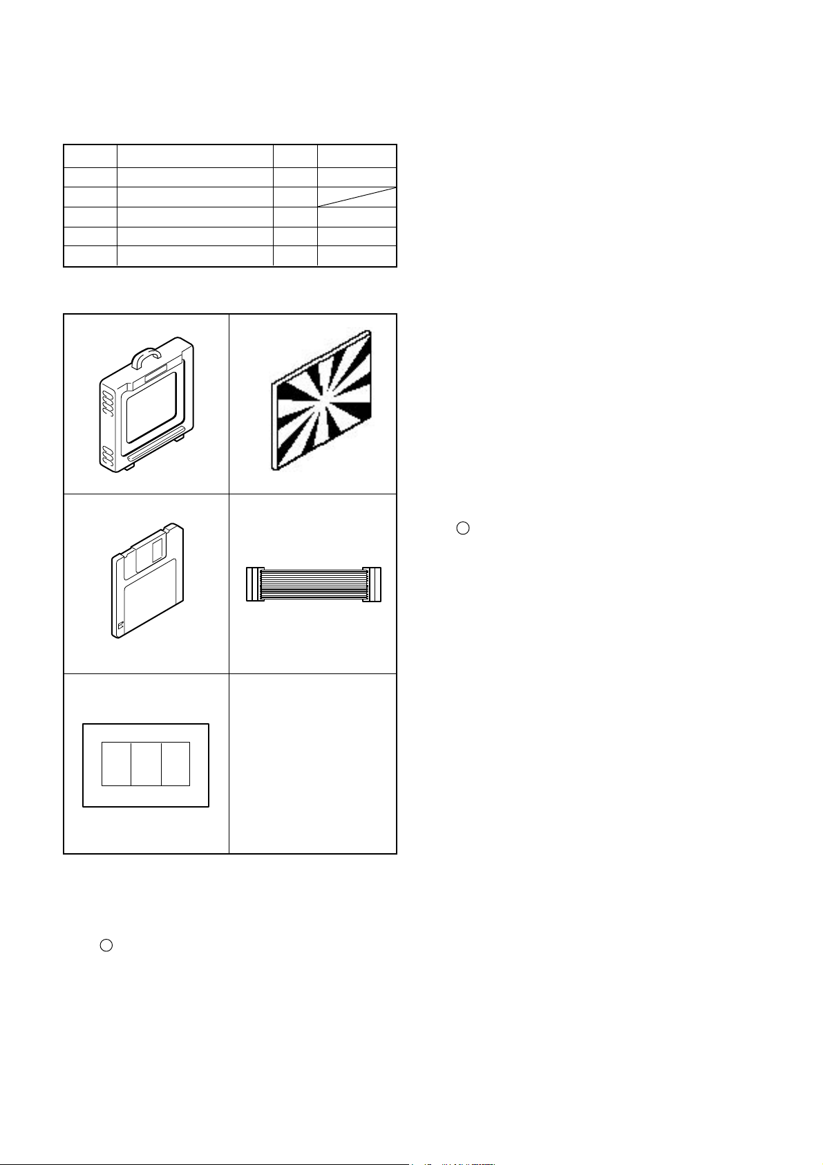
[ 1 ] Table for Servicing Tools
Ref. No. Name
J-1
Color viewer 5,100 K
J-2
Siemens star chart
J-3
Calibration software
J-4
Extension cord
J-5
Chart for color adjustment
Note: J-1 color viewer is 100 - 110 VAC only.
Qt’y
1
1
1
1
1
J-1 J-2
J-3
J-4
Part code
VJ8-0007
VJ8-0167
VJ8-0157
VJ8-0155
[ 3 ] Adjustment Items and Order
1. IC501 Oscillation Frequency Adjustment
2. 5.0 V (D) Voltage Adjustment
3. 13.5 V (L) Voltage Adjustment
4. AWB Adjustment
5. Color Matrix Adjustment
6. Lens Adjustment
7. CCD Defect Detect Adjustment
8. LCD Panel Adjustment
8-1. LCD H AFC Adjustment
8-2. LCD RGB Offset Adjustment
8-3. LCD Gain Adjustment
8-4. LCD Blue Brightness Adjustment
8-5. LCD Red Brightness Adjustment
8-6. LCD VcomPP Adjustment
Note:
1. If the lens, CCD, optical filter, board, changing the part
and disassemble around the lens in item 4-7 replace, it is
necessary to adjust again. 4-7 adjustments should be
carried out in sequence.
[ 4 ] Setup
1. System requirements
Windows 95 or 98
IBM R -compatible PC with 486 or higher processor
CD-ROM drive
3.5-inch high-density diskette drive
Serial port with standard RS-232C interface
8 MB RAM
Hard disk drive with at least 15 MB available
VGA or SVGA monitor with at least 256-color display
J-5
[ 2 ] Equipment
1. Oscilloscope
2. Digital voltmeter
3. AC adaptor
4. IBM R -compatible PC
5. DC regulated power supply
2. Installing calibration software
1. Insert the calibration software installation diskette into
your diskette drive.
2. Open Explorer.
3. Copy the DSC Cal folder on the floppy disk in the FD drive
to a folder on the hard disk.
4. Create a shortcut for the file DscCal_v123c.exe by drag-
ging and dropping it from the copied DscCal folder to the
Desktop or to another folder.
5. Right-click the shortcut icon to specify the command line
options.
6. Click Properties, and then click the Shortcut tab. Type a
space and then the numeral “ 3 “ (in single-byte charac
ters)at the end of the link destination. (*****.exe 3)
7. Click the OK button in the dialog box to finish.
3. Color Viewer
Turn on the switch and wait for 30 minutes for aging to take
place before using Color Viewer.
SERVER_DIS
C-2 Ver.2
C. ADJUSTMENT METHOD
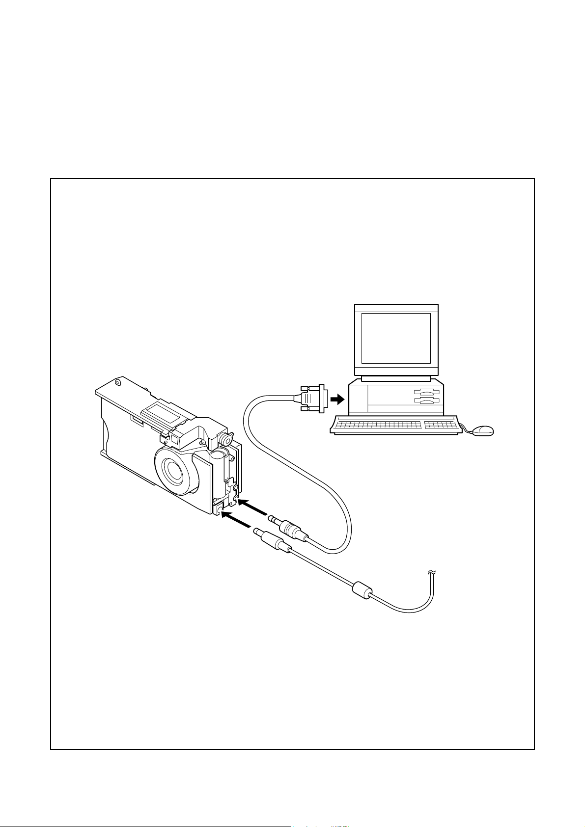
[ 5 ] Connecting the camera to the computer
1. Turn off both camera and computer.
2. Locate the port cover on the side of the camera. Press on the arrows and slide the cover down to open it.
3. Line up the arrow on the cable connector with the notch on the camera's serial port. Insert the connector.
4. Locate a serial port on the back of your computer. You may have two serial ports labeled COM1 and COM2, or the ports may
be labeled with icons. If you have two serial ports available, use port 1 to connect your camera.
5. Line up the serial connector on the cable with one of the serial ports on your computer, and insert the connector.
6. Turn on the camera and your computer system.
To COM1 or COM2 serial port
Serial cable
AC adaptor
Ver.2
C-3
SERVER_DIS
 Loading...