

Page 1

C. ADJUSTMENT METHOD
C-920ZOOM/D-450ZOOM
C. ADJUSTMENT METHOD
[1] TABLE FOR SERVICING TOOLS .......................................................................... C-2
[2] EQUIPMENT ........................................................................................................... C-2
[3] ADJUSTMENT ITEMS AND ORDER ..................................................................... C-2
[4] SETUP ....................................................................................................................C-2
[5] CONNECTING THE CAMERA TO THE COMPUTER ............................................C-3
[6] ADJUSTMENT ........................................................................................................C-4
1. IC501 OSCILLATION FREQUENCY ADJUSTMENT ....................................... C-4
2. 5.0 V (A) VOLTAGE ADJUSTMENT.................................................................. C-4
3. 13.0 V (D) VOLTAGE ADJUSTMENT ............................................................... C-4
4. AWB ADJUSTMENT .........................................................................................C-4
5. COLOR MATRIX ADJUSTMENT ......................................................................C-4
6. CCD DEFECT DETECT ADJUSTMENT .......................................................... C-5
7. LENS ADJUSTMENT .......................................................................................C-5
8. LCD PANEL ADJUSTMENT............................................................................. C-5
8-1. LCD H AFC ADJUSTMENT .......................................................................C-5
8-2. LCD GAIN ADJUSTMENT ......................................................................... C-5
8-3. LCD RGB OFFSET ADJUSTMENT ...........................................................C-6
8-4. LCD RED BRIGHTNESS ADJUSTMENT ................................................. C-6
8-5. LCD BLUE BRIGHTNESS ADJUSTMENT ...............................................C-6
8-6. LCD TINT ADJUSTMENT (FOR PAL) ....................................................... C-6
[7] ADJUSTMENT VALUE ........................................................................................... C-7
SIEMENS STAR CHART ................................................................................................C-8
CHECKING OF LENS UNIT ...........................................................................................C-9
SERVER_DIS
C-1
Ver.1/Rev.3
Page 2
C. ADJUSTMENT METHOD
C-920ZOOM/D-450ZOOM
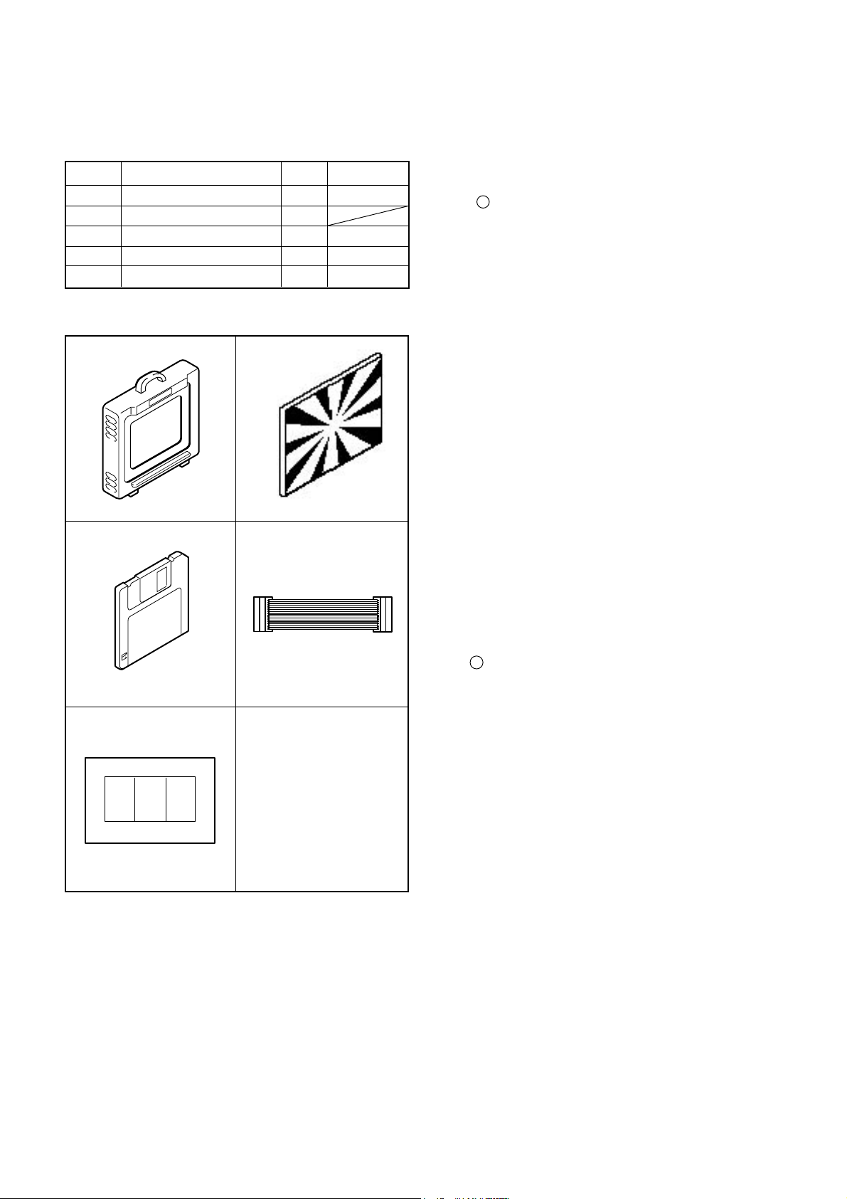
[ 1 ] Table for Servicing Tools
Ref. No. Name
J-1
Color viewer 5,100 K
J-2
Siemens star chart
J-3
Calibration software
J-4
Extension cord
J-5
Chart for color adjustment
Note: J-1 color viewer is 100 - 110 VAC only.
Qt’y
1
1
1
1
1
J-1 J-2
J-3
J-4
Part code
VJ8-0007
VJ8-0159
VJ8-0157
VJ8-0155
[ 2 ] Equipment
1. Oscilloscope
2. Digital voltmeter
3. AC adaptor
4. IBM R -compatible PC
5. DC regulated power supply
[ 3 ] Adjustment Items and Order
1. IC501 Oscillation Frequency Adjustment
2. 5.0 V (A) Voltage Adjustment
3. 13.0 V (D) Voltage Adjustment
4. AWB Adjustment
5. Color matrix Adjustment
6. CCD Defect Detect Adjustment
7. Lens Adjustment
8. LCD Panel Adjustment
8-1. LCD H AFC Adjustment
8-2. LCD Gain Adjustment
8-3. LCD RGB Offset Adjustment
8-4. LCD Red Brightness Adjustment
8-5. LCD Blue Brightness Adjustment
8-6. LCD Tint Adjustment (for PAL)
Note:
1. If the lens, CCD, optical filter, board, changing the part
and disassemble around the lens in item 4-7 replace, it is
necessary to adjust again. Item 4-7 adjustments other
than these should be carried out in sequence.
J-5
[ 4 ] Setup
1. System requirements
Windows 95 or 98
IBM R -compatible PC with 486 or higher processor
CD-ROM drive
3.5-inch high-density diskette drive
Serial port with standard RS-232C interface
8 MB RAM
Hard disk drive with at least 15 MB available
VGA or SVGA monitor with at least 256-color display
2. Installing calibration software
1. Insert the calibration software installation diskette into
your diskette drive.
2. Open Explorer.
3. Copy the DSC Cal folder on the floppy disk in the FD drive
to a folder on the hard disk.
3. Color Viewer
Turn on the switch and wait for 30 minutes for aging to take
place before using Color Pure.
SERVER_DIS
C-2
Ver. 1
Page 3
C-920ZOOM/D-450ZOOM
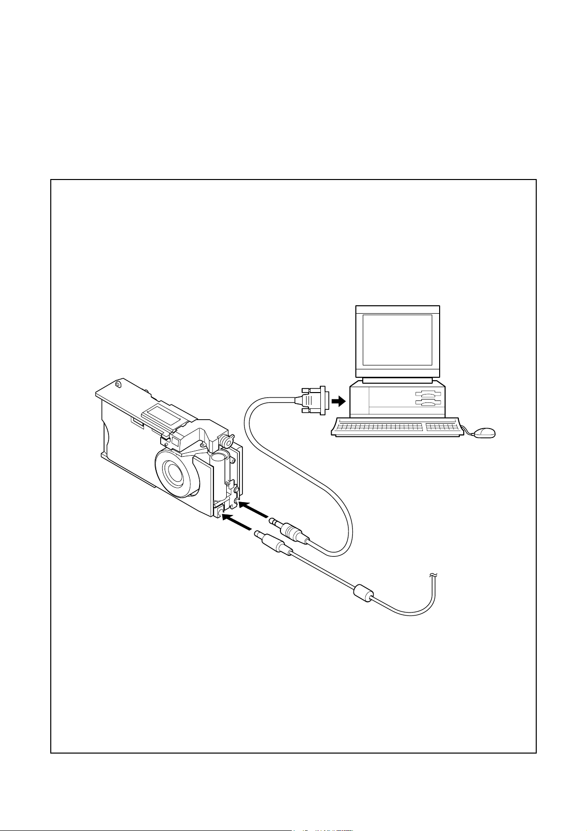
[ 5 ] Connecting the camera to the computer[ 5 ] Connecting the camera to the computer
[ 5 ] Connecting the camera to the computer
[ 5 ] Connecting the camera to the computer[ 5 ] Connecting the camera to the computer
1. Turn off both camera and computer.
2. Locate the port cover on the side of the camera. Press on the arrows and slide the cover down to open it.
3. Line up the arrow on the cable connector with the notch on the camera's serial port. Insert the connector.
4. Locate a serial port on the back of your computer. You may have two serial ports labeled COM1 and COM2, or the ports
may be labeled with icons. If you have two serial ports available, use port 1 to connect your camera.
5. Line up the serial connector on the cable with one of the serial por ts on your computer, and insert the connector.
6. Turn on the camera and your computer system.
C. ADJUSTMENT METHOD
To COM1 or COM2 serial port
Serial cable
AC adaptor
Ver.1
C-3
SERVER_DIS
Page 4
[ 6 ] Adjust Specifications
Serial cable
Camera
15 cm ± 1 cm
All white pattern color
viewer (5,100K) and
color matrix adjustment chart
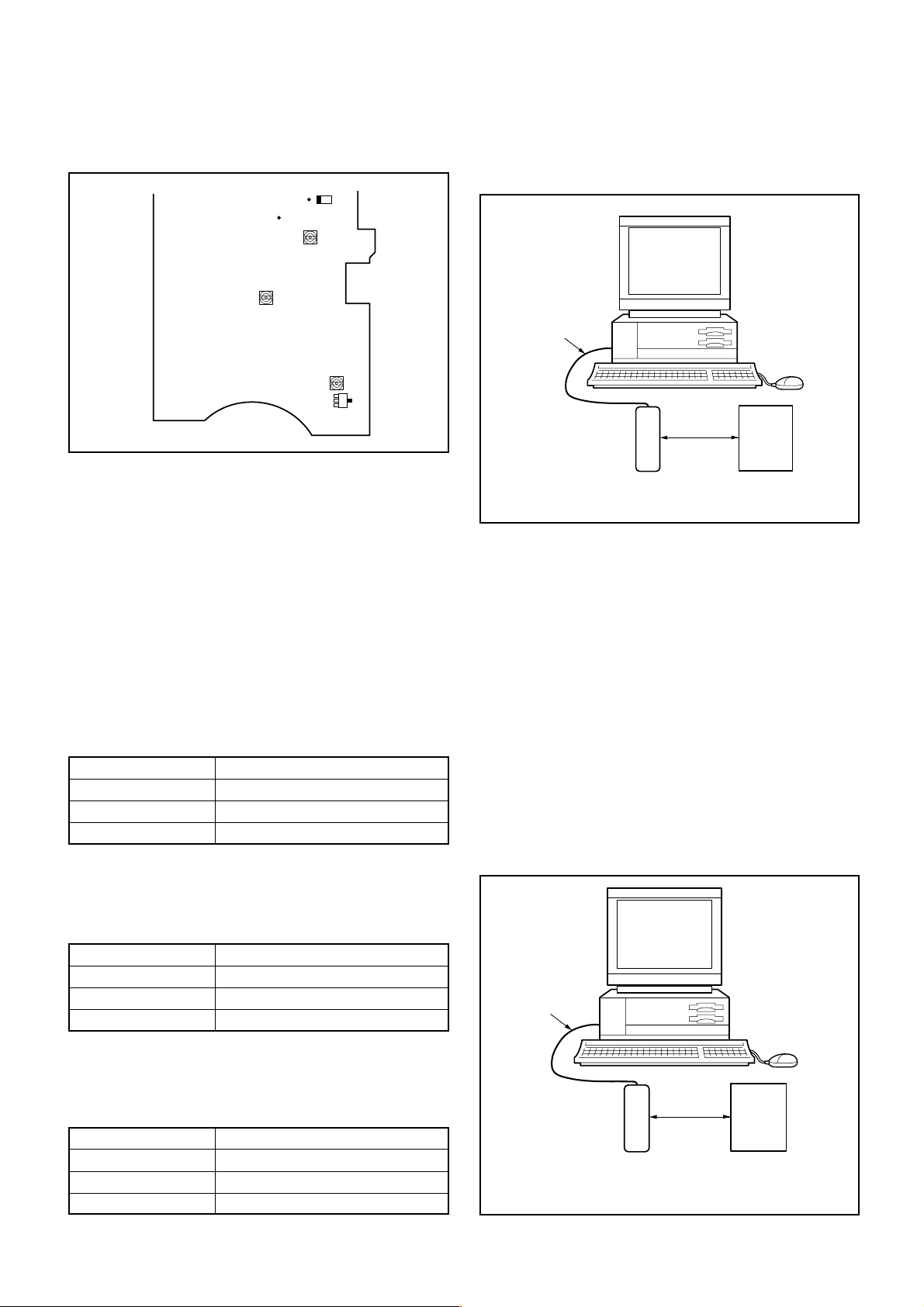
[ST1 board (Side B)]
CL523
CL538
VR504
VR501
C5053
VR502
Collector
C. ADJUSTMENT METHOD
Q5001
C-920ZOOM/D-450ZOOM
Adjustment method:
1. Adjust with VR504 to 13.00 ± 0.10 V.
4. AWB Adjustment
Serial cable
Camera
0 - 18 cm
Note:
Voltage adjustment is necessary to repair in the ST1 board
and replace the parts. Adjustments of the service-supplied
circuit board assembly has been completed.
Preparation:
1. Short Pins 1 and 2 of the S1401 card switch on the ST1
circuit board.
2. Connect the ST1 board and the CA1 board with two
extension cords.
3. Connect LCD panel.
4. Insert the card.
5. Turn on the power switch, and then set the camera mode.
6. Turn on the LCD monitor switch.
1. IC501 Oscillation Frequency Adjustment
Measuring Point
Measuring Equipment
ADJ. Location
ADJ. Value
Adjustment method:
1. Adjust with VR501 to 200 ± 1 kHz.
Q5001 Collector
Frequency counter
VR501
200 ± 1 kHz
All white pattern
Color viewer (5,100K)
Preparation:
POWER switch: ON
Adjusting method:
1. When setting the camera in place, set it to an angle so that
nothing appears in any part of the color viewer except the
white section. (Do not enter any light.)
2. Double-click on the DscCalV122.
3. Click the AWB, and click the Yes.
4. AWB adjustment value will appear on the screen.
(Adjustment value is 249-255 indicates an error.)
If the initial value for a0 is 249-255, the display will show
that the evaluated value required for adjustment could not
be obtained. The cause of this might be a lens
malfunctionor an open circuit in the CCD output signal
line.
5. Click the OK.
5. Color Matrix Adjustment
2. 5.0 V (A) Voltage Adjustment
Measuring Point
Measuring Equipment
ADJ. Location
ADJ. Value
Adjustment method:
1. Adjust with VR502 to 5.00 ± 0.10 V.
CL523
Digital voltmeter
VR502
5.00
± 0.10 V
3. 13.0 V (L) Voltage Adjustment
Measuring Point
Measuring Equipment
ADJ. Location
ADJ. Value
SERVER_DIS
CL531
Digital voltmeter
VR504
13.00 ± 0.10 V
C-4
Ver. 1
Page 5

C-920ZOOM/D-450ZOOM
C. ADJUSTMENT METHOD
Preparation:
POWER switch: ON
Adjustment method:
1. Set the color adjustment chart to the color viewer.
(Do not enter any light.)
2. Set the color adjustment chart so that it becomes center of
the screen.
3. Double-click on the DscCalV122.
4. Click the UV Matrix, and click the Yes.
5. Four color matrix (UVMAT0, UVMAT1, UVMAT2 and
UVMAT3) adjustment values will appear on the screen.
6. Click the OK.
6. CCD Defect Detect Adjustment
Adjustment method:
1. Double-click on the DscCalV122.
2. Select the “ CCD Defect Detection “ from Test window,
and click the “ Yes “.
3. After the adjustment is completed, OK will display.
4. Click the OK.
7. Lens Adjustment
8. LCD Panel Adjustment
[CA1 board (Side A/B)]
CL141
CL416
CL415
8-1. LCD H AFC Adjustment
Preparation:
POWER switch: ON
Adjusting method:
1. Double-click on the DscCalV122.
2. Select 0 on the LCD “ H AFC “.
3. While watching the LCD monitor, adjust LCD “ H AFC “ so
that the edge of the LCD adjustment frame are the same
distance from the left and right edge of the LCD screen.
(A = B)
Camera
Approx.
150 cm ± 3 cm
Siemens
star chart
Preparation:
POWER switch: ON
Adjustment condition:
Siemens star chart (A3)
Fluorescent light illumination with no flicker
Illumination above the subject should be 400 lux
± 10%.
Adjustment method:
1. Set the siemens star chart 150 cm ± 3 cm so that it becomes center of the screen.
2. Double-click on the DscCalV122.
3. Click the Focus, and Click the Yes.
4. Flange-back adjustment value will appear on the screen.
If an error is made in adjustment, the following value will
result.
0: Incorrect adjustment precision (large difference when
adjusting and checking)
1: Iris NG
5. Click the OK.
Ver.1
LCD
LCD
A
adjustment
B
frame
screen
FPC
8-2. LCD Gain Adjustment
Adjusting method:
1. Double-click on the DscCalV122.
2. Adjust LCD “ Gain “ so that the amplitude of the CL416
waveform is 1.0 V
C-5
± 0.1 Vp-p.
CL416 waveform
SERVER_DIS
1.0V
±0.1Vp-p
Page 6

C. ADJUSTMENT METHOD
8-3. LCD RGB Offset Adjustment
Adjusting method:
1. Double-click on the DscCalV122.
2. Adjust LCD “ RGB Offset “ so that the amplitude of the
CL416 waveform is 4.6 V
Note:
8-2. LCD Gain adjustment should always be carried out first.
± 0.1 Vp-p.
4.6V
±0.1Vp-p
CL416 waveform
8-4. LCD Red Brightness Adjustment
Adjusting method:
1. Adjust LCD “ R Bright “ so that the amplitude of the CL415
waveform is VG
waveform.
Note:
8-2. LCD Gain adjustment and 8-3. LCD RGB Offset adjustment should always be carried out first.
± 0.1 Vp-p with respect to the CL416 (VG)
C-920ZOOM/D-450ZOOM
8-5. LCD Blue Brightness Adjustment
Adjusting method:
1. Adjust LCD “ B Bright “ so that the amplitude of the CL414
waveform is
waveform.
Note:
8-2. LCD Gain adjustment and 8-3. LCD RGB Offset adjustment have done.
± 0.1 Vp-p with respect to the CL416 (VG)
VG
Waveform (CL416)
VG±
0.1Vp-p
Waveform (CL416)
Waveform (CL415)
VG
VG±
0.1Vp-p
Waveform (CL414)
8-6. LCD Tint Adjustment (for PAL)
Adjusting method:
1. Adjust LCD “ Tint “ so that the amplitude of CL414
waveform is minimum.
Note:
8-6. LCD TINT adjustment should always be carried out last.
a
a
SERVER_DIS
C-6
Ver. 1
Page 7

C-920ZOOM/D-450ZOOM
C. ADJUSTMENT METHOD
[ 7 ] Adjustment [ 7 ] Adjustment
[ 7 ] Adjustment
[ 7 ] Adjustment [ 7 ] Adjustment
Explanation of adjustment valuesExplanation of adjustment values
Explanation of adjustment values
Explanation of adjustment valuesExplanation of adjustment values
Adjustment values are values which have been estimated
statistically from the distribution of adjustment values obtained from similar machine models and prototypes. Accordingly these values should be used as a guide only.
Because these values are guides, equipment which is in
good working order may still produce values which are outside the adjustment value ranges, so that the equipment
should be operated in order to determine whether it is in fact
operational or defective.
Range of adjustment valuesRange of adjustment values
Range of adjustment values
Range of adjustment valuesRange of adjustment values
(1) A(1) A
WB adjustment rangWB adjustment rang
(1) A
WB adjustment rang
(1) A(1) A
WB adjustment rangWB adjustment rang
R: 150 to 400
G: 128 (fixed value)
B: 150 to 400
Note : If adjustment value “a0” is following value,
it means adjustment NG.
a0 = 254, 0, 0, 0, 254
(2) Color matrix adjustment ranges(2) Color matrix adjustment ranges
(2) Color matrix adjustment ranges
(2) Color matrix adjustment ranges(2) Color matrix adjustment ranges
UVMAT0: 40 to 160
UVMAT1: 180 to 256, 0 to 60
UVMAT2: 180 to 256, 0 to 60
UVMAT3: 40 to 160
VV
aluesalues
V
alues
VV
aluesalues
eses
es
eses
Adjustment values are normal except following cases.
a) It does not detect any signal from CCD. In this case,
adjustment values are all “1”.
UVMAT0: 1
UVMAT1: 1
UVMAT2: 1
UVMAT3: 1
b) Abnormal adjustment values judged by UMAT3 value.
UVMAT3: 0 (Nor mal)
UVMAT3: 2 (Aperture error)
UVMAT3: 3 (Shutter speed error)
UVMAT3: 4 (Zoom sensor (PR) error)
(3) Lens adjustment ranges(3) Lens adjustment ranges
(3) Lens adjustment ranges
(3) Lens adjustment ranges(3) Lens adjustment ranges
Adjustment value : Within 30 and 140
Note : Adjustment value is “ 0 “ means NG.
Ver.1
C-7
SERVER_DIS
Page 8

C. ADJUSTMENT METHOD C-920ZOOM/D-450ZOOM
C-8 Ver. 1
Page 9
C-920ZOOM / D-420ZOOM C.ADJUSTMENT METHOD
CHECKING OF LENS UNIT
1. Check Item
1)Backlash Pulse of LD
2)LD ERROR Pulse
3)Basklash Pulse of ZOOM
4)ZOOM ERROR Pulse
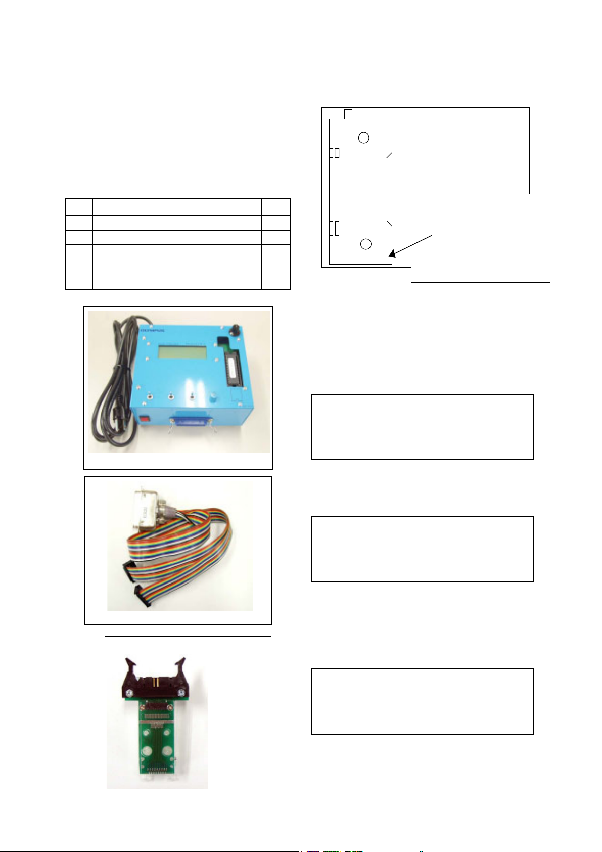
2. Tools
1
2
3
4
5
Part No.
KC0331
KC0333
KC0338
FPC-Adaptor
FPC-Adaptor
Description
Lens Checker LCK1
Connector Cable P4
Clip Connector 17
12-PINS for K-FPC
10-PINS for S-FPC
Q’ty
1
1
2
1
1
3. Checking Prosedure
Fi x 2 FPC-Adaptors (10 and 12 PINS) to ClipConnector
17.
Connect Connector Cable P4, Clip Connector 17
and Lens Checker LCK-1
1) AUTO
I. Tum on Lens Checker LCK-1
080-10
FPC-Adaptor 12
PINS for K-FPC
FPC-Adaptor 10
PINS for S-FPC
The last 2 digits are mean-
ing the number of Pin.
Ex.) 080-10 :10PINS
Lens Checker LCK-1
Connector Cable P4
Initial Setting
II. Set AUTO / MANU SW at AUTO
III.Set Dial SW at 0
IV. Set CW / CCW SW at CW
LCK-1 Ver.1 0 Auto
PUSH START SW
(0 : Number of Dial SW 0-5)
V. Connect the both FPCs (K-FPC and S-FPC) to
Clip Connectors. Hold a lens unit by hand, and keep
it horizontally.
VI. Push START SW. (More than 0.2 sec.)
LCK-1 Ver.1 0 Auto
ZOOM RESET
Clip Connector 17
C-9Ver. 1/Rev.3
Page 10

C.ADJUSTMENT METHOD
C-920ZOOM / D-420ZOOM
When an error occurs, an error is indicated, and it stops.
LCK-1 Ver.1 0 Auto
LD RESET
LCK-1 Ver.1 0 Auto
LD BACKLASH CHK
LB*
* is BACKLASH PULSE of LD
LCK-1 Ver.1 0 Auto
LD D CHK
LB1 D *
* is LD ERROR PULSE
LCK-1 Ver.1 0 Auto
ZOOM BACKLASH CHK
LB1 D1 ZB *
* is BACKLASH PLUSE of ZOOM
In case of GOOD
LCK-1 Ver.1 0 Auto
PUSH START SW
LB1 D1 ZB1 D12
GOOD
In case of NG :
LCK-1 Ver.1 0 Auto
PUSH START SW
LB D6
NO GOOD ZM D Err
ERROR is indicated
(The indication which isn’t being explained is the condition
of PR and PI.)
When CW/CCW SW is set at CCW, the automatic check of
the motor chosen with a LD/ZOOM SW is done.
2) Manual
I. Set AUTO/MANU SW at MANU
LCK-1 Ver.1 0 Manu
LD CW
LCK-1 Ver.1 0 Auto
ZOOM D CHK
LB1 D1 ZB1 D * *
* * is ZOOM ERROR PULSE (ZOOM AREA : SET-UP AREA)
The contents chosen with the LD/ZOOM SW and the CW/
CCW SW indicated in LCD.
II. Push START SW (More than 0.2 sec.)
LCK- Ver.1 0 Manu
LD CW
MOVE
When a motor works, “MOVE” is indicated in LCD.
C-10 Ver. 1/Rev.3
Page 11

C-920ZOOM / D-420ZOOM C.ADJUSTMENT METHOD
LD Motor
When PI signal 500 pulses (500pps) are changed,LD motor
stops
CW : Turn Out CCW : Tum In
ZOOM Motor
When PI signal 2200 pulses (300pps) are changed, ZOOM
motor stops
CW : W to T CCW : T to W
4. Others
Turn off LCK-1 promptly if something is wrong.
5, ERROR Indication
PI, PR Err : PI or PR Pulse does not change.
LD BK Err : LD BACKLASH PULSE is out of standard.
LD D Err : LD Pulse Error
ZD BK Err : ZOOM BACKLASH PULSE is out of
standard
ZD D Err : ZOOM Pulse Error
C-11Ver. 1/Rev.3
 Loading...