

Page 1

C-8080Wide Zoom
C. ADJUSTMENT METHOD
[1] TABLE FOR SERVICING TOOLS .......................................................................... C-2
[2] EQUIPMENT ........................................................................................................... C-2
[3] ADJUSTMENT ITEMS AND ORDER ...................................................................... C-2
[4] SETUP .................................................................................................................... C-2
[5] CONNECTING THE CAMERA TO THE COMPUTER ............................................ C-3
[6] USB STORAGE INFORMATION REGISTRATION ................................................. C-4
[7] ADJUST SPECIFICATIONS.................................................................................... C-5
1. AF LED ANGLE ADJUSTMENT ......................................................................... C-5
2. PAF SENSOR UP-DOWN ADJUSTMENT ......................................................... C-5
3. LENS ADJUSTMENT ......................................................................................... C-7
4. AWB ADJUSTMENT ........................................................................................... C-8
5. CCD WHITE POINT DEFECT DETECT ADJUSTMENT ................................... C-8
6. CCD BLACK POINT AND WHITE POINT DEFECT DETECT
ADJUSTMENT IN LIGHTED...... C-9
7. PAF ADJUSTMENT ............................................................................................C-9
7-1. PARALLAX ADJUSTMENT ....................................................................... C-9
7-2. DISTANCE ADJUSTMENT ...................................................................... C-10
8. LCD PANEL ADJUSTMENT............................................................................. C-11
8-1. LCD H AFC ADJUSTMENT ..................................................................... C-11
8-2. LCD RGB OFFSET ADJUSTMENT ......................................................... C-11
8-3. LCD GAIN ADJUSTMENT ....................................................................... C-11
8-4. LCD RED BRIGHTNESS ADJUSTMENT................................................ C-11
8-5. LCD BLUE BRIGHTNESS ADJUSTMENT ............................................. C-12
8-6. LCD VcomDC ADJUSTMENT ................................................................. C-12
9. EVF ADJUSTMENT ..........................................................................................C-12
9-1. EVF H AFC ADJUSTMENT ......................................................................C-12
9-2. EVF RGB OFFSET ADJUSTMENT ......................................................... C-13
9-3. EVF GAIN ADJUSTMENT ........................................................................C-13
9-4. EVF RED BRIGHTNESS ADJUSTMENT ................................................C-13
9-5. EVF BLUE BRIGHTNESS ADJUSTMENT..............................................C-13
[8] ADJUSTMENT ITEMS ..........................................................................................C-15
C-1 Ver.1
Rev.1
Page 2

C. ADJUSTMENT METHOD C-8080Wide Zoom
[1] Table for Servicing Tools
Ref. No.
J-1
Pattern box (color viewer)
Siemens star chart
J-2
Calibration software
J-3
J-4
Chroma meter
J-5
Spare lamp
J-6
Target board
J-7 1
PAF sensor up-down adjustment chart
J-8 1
Parallax adjustment chart
J-9
0.5 m distance adjustment chart
J-10
J-11
Note: J-1 color viewer is 100 ± 10 VAC only.
Use J-10 collimator made by Kyoritsu Electric Co. Ltd. or
equivalent of it. (f= 180 [mm] or more,Ø= 50 [mm] or more)
2.4 m distance adjustment chart
Collimator
Name Part code
Number
1
1
1
1
1
1
1
1
1
KC0336
KC0337
KC0339
J-1 J-2
J-3
J-4
[2] Equipment
1. Oscilloscope, 2. Digital voltmeter
3. AC adaptor
4. PC (IBM ®-compatible PC, Pentium processor, Windows
98 or Me or 2000 or XP)
[3] Adjustment Items and Order
1. AF LED Angle Adjustment
2. PAF Sensor Up-down Adjustment
3. Lens Adjustment
4. AWB Adjustment
5. CCD White Point Defect Detect Adjustment
6. CCD Black Point And White Point Defect Detect Adjustment in Lighted
7. PAF Adjustment
7-1. Parallax Adjustment
7-2. Distance Adjustment
8. LCD Panel Adjustment
8-1. LCD H AFC Adjustment
8-2. LCD RGB Offset Adjustment
8-3. LCD Gain Adjustment
8-4. LCD Red Brightness Adjustment
8-5. LCD Blue Brightness Adjustment
8-6. LCD VcomDC Adjustment
9. EVF Adjustment
9-1. EVF H AFC Adjustment
9-2. EVF RGB Offset Adjustment
9-3. EVF Gain Adjustment
9-4. EVF Red Brightness Adjustment
9-5. EVF Blue Brightness Adjustment
Note:
1. If the lens, CCD, board and changing the part in item 3-
6 replace, it is necessary to adjust again.
J-5 J-6
[4] Setup
1. System requirements
Windows 98 or Me or 2000 or XP
IBM ®-compatible PC with pentium processor
CD-ROM drive
3.5-inch high-density diskette drive
USB port
40 MB RAM
Hard disk drive with at least 15 MB available
VGA or SVGA monitor with at least 256-color display
2. Installing calibration software
1. Insert the calibration software installation diskette into
your diskette drive.
2. Open Explorer.
3. Copy the DscCalDI_131 folder on the floppy disk in the
FD drive to a folder on the hard disk.
3. Installing USB driver
Install the USB driver with camera or connection kit for PC.
C-2 Ver. 1
Page 3
C. ADJUSTMENT METHODC-8080Wide Zoom
4. Pattern box (color viewer)
Turn on the switch and wait for 30 minutes to stabilize color temperature before using. It is used after adjusting the
chroma meter adjust color temperature to 3100 ± 20 K and luminosity to 900 ± 20 cd/m
its circumference are high temperature during use and after power off for a while.
2
. Be careful of handling the lamp and
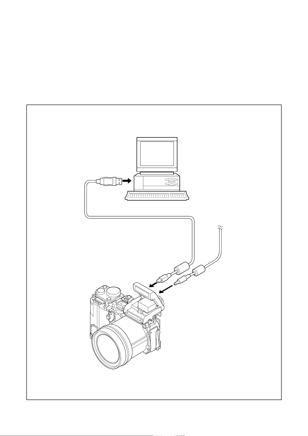
[5] Connecting the camera to the computer
1. Line up the arrow on the cable connector with the notch on the camera's USB port. Insert the connector.
2. Locate a USB port on your computer.
To USB port
USB cable
AC adaptor
C-3Ver. 1
Page 4
C. ADJUSTMENT METHOD C-8080Wide Zoom
[6] USB Storage Information Registration
USB storage data is important for when the camera is connected to a computer via a USB connection.
If there are any errors in the USB storage data, or if it has
not been saved, the USB specification conditions will not be
satisfied, so always check and save the USB storage data.
Preparation:
POWER switch: ON
Adjustment method:
1. Connect the camera to a computer. (Refer to [5] Connecting the camera to the computer on the page C-3.)
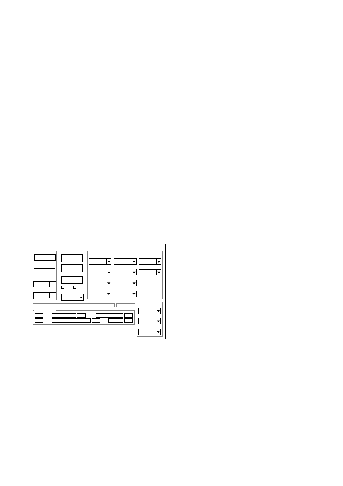
2. Double-click on the DscCalDi.exe in the DscCalDi131.
3. Click on the Get button in the USB storage window and
check the USB storage data.
VID: OLYMPUS
PID: C8080WZ
Serial:
Rev. : 1.00
4. Check the “Serial” in the above USB storage data. If the
displayed value is different from the serial number printed
on the base of the camera, enter the number on the base
of the camera. Then click the Set button.
5. Next, check VID, PID and Rev. entries in the USB storage data. If any of them are different from the values in
3. above, make the changes and then click the corresponding Set button.
Calibration
AWB
Focus
UV Matrix
Cal Mode
Cal Data
USB storage
VID
Get
PID
Set
OK
OK
Upload
Firmware
Image
PAF Cal.
EVF
LCD Type
LCD
R Bright
RGB Offset
Tint
VCO
H AFC Test
Serial
Set
Set
Rev.
B Bright
Gain
Phase
Set
Set
VCOMDC
VCOMPP
Setting
Language
Video Mode
Factory Code
C-4 Ver. 1
Page 5

C. ADJUSTMENT METHODC-8080Wide Zoom
[7] Adjust Specifications
1. AF LED Angle Adjustment
[CP1 board (Side B)]
CL456(VG)
CL455(VR)
CL427(CSYNC)
CL301
CL302
70 cm
CL423(B)
CL422(R)
CL421(G)
CL457(VB)
CL451(TCOM)
CL452
(HDO)
width
of 1cm
black
line
CL424
(EN)
white
or gray
Adjustment condition:
1. This adjustment should be carried out in a fairly dark
place so that the shape of the LED spot can be checked.
2. After adjustment, the readjustment is necessary to re-
place the lens, FPC unit and CA1 board.
3. Do not see the light of AF LED directly.
4. Do not adjust long time.
Adjustment method:
1. Set the camera so that the target board is at a distance of
1 meters from LED. (Light up the target board.)
2. Connect CL301 and CL302. Connect the camera and com-
puter by USB cable. Connect TV monitor with AV cable.
3. Turn on the power, double-click on the DscCalDi.exe.
4. Click the LCD “Test”. Select the “AF LED” after select
“Monitor”.
5. Carry out the pre-focus adjustment. After adjusting, the
target mark will appear on the monitor.
6. Turn off the light of target board.
7. Turn the screws on FPC unit to adjust so that the cen-
ter of the LED spot appears inside the circle above the
target mark on the target board surface.
8. After adjusting, click the LCD “Test”, and select the “LCD
OFF”. (The lens will be stowed.)
2. PAF Sensor Up-down Adjustment
70 cm
Target board
Target
LED
spot
mark
Setting the adjustment mode
1. Open the card cover of the camera.
2. Turn on the power switch. “CARD-COVER OPEN” will be
displayed in the LCD.
3. Push the LCD button and OK button more than 3 seconds simultaneously.
4. Push the right arrow button, and select “STORAGE”.
5. “STORAGE/CONTROL” will be displayed.
6. Push the below arrow button, and select “CONTROL”.
7. Push the OK button.
8. Close the card cover of the camera.
Camera
1 m ± 1cm
PAF sensor up-down
adjustment chart
C-5Ver. 1
Page 6

V
e
p
40mm
guide line
m
width: 0.5mm
C. ADJUSTMENT METHOD C-8080Wide Zoom
a. If the level at the left side of the sensor output wave pat-
tern is high, adjust the edge of the lower wave pattern
so that it is aligned with the gray guide line.
200m
24.6
mm
400mm
a.
gray guide
line
aligned with
this line
edge of
wave
pattern
280mm
280mm
PAF sensor up-down adjustment chart (size: A2)
Preparation:
POWER switch: ON
Adjustment method:
1. Set the PAF sensor up-down adjustment chart at 1 m ± 1
cm from PAF sensor.
2. Double-click on the DscCalDi.exe.
3. Click the “PAF Cal”. “PAF Calibration Dialog” is opened.
4. Click the “ON” in the PAF Disp. Sensor data graph will be
displayed.
5. While watching the LCD display, adjust the vertical angle
as shown in the diagram below. The guide line on the chart
should overlap with the cross-shaped guide that appears
on-screen on the LCD display.
5.
Guide line
on the chart
Cross-shaped guide
on-screen on the
LCD display
In case of the level at the left side
of the sensor output wave pattern
is high
b. If the level at the right side of the sensor output wave
pattern is high, adjust the edge of the upper wave pattern
so that it is aligned with the gray guide line.
b.
In case of the level at the right side
of the sensor output wave pattern
is high
edge of
wave
pattern
aligned with
this line
gray guide
line
7. While watching the values at the top of the LCD display,
turn the screw to adjust the angle of the PAF sensor until
both the left and right values are between 850 and 1000.
(If the heights of the wave patterns do not remain the same
and the values do not rise above 850 when the screw is
turned, it is possible that the sensor may be installed in
correctly.)
7.
6. While changing the angle of the camera and watching
Adjust so that these value
are between 850-1000.
LEFT : 850 RIGHT : 850
the LCD display, adjust the horizontal angle as shown in
the diagram below.
alue will increase while left and right wav
atterns remain at about the same height.
8. Fix the PAF adjustment screw. (Refer to page B-2)
C-6 Ver. 1
Page 7

3. Lens Adjustment
Perform either the method A or the method B.
Method A
C. ADJUSTMENT METHODC-8080Wide Zoom
Method B
CAMERA
Collimator
(Set up to the infinity.)
CAMERA
(Tele end)
20 cm ± 1 cm
Siemens star chart
Preparation:
POWER switch: ON
Set up the collimator to the infinity.
Note:
Do not vibrate during the adjustment.
Either the collimator infinity adjustment or the 20 cm adjustment can be used.
Adjustment method:
1. Set the camera so that it becomes center of the screen in
the collimator.
2. Double-click on the DscCalDi.exe.
3. Select “Infinity Cal” in the LCD “Test”.
4. Infinity adjustment value will appear on the screen.
5. Set the siemens star chart is at a distance of 20 ± 1 cm
from the lens (Tele end) so that it becomes center of the
screen. (A chart that is at least 1/4 the size of the screen
should be used at the Wide end.)
6. Click the “Focus”, and Click the “Yes”.
7. 20 cm adjustment value will appear on the screen.
8. Click the OK.
CAMERA
(Tele end)
CAMERA
(Tele end)
3 m
Siemens star chart
20 cm ± 1 cm
Siemens star chart
Preparation:
POWER switch: ON
Note:
Do not vibrate during the adjustment.
Either the 3 m adjustment or the 20 cm adjustment can be
used.
Adjustment method:
1. Write the special firmware for adjustment to the camera.
(Refer to D-3 for update procedure.)
Version : v757-FOCUS
2. Set the siemens star chart is at a distance of 3 m from the
lens (Tele end) so that it becomes center of the screen.
3. Double-click on the DscCalDi.exe.
4. Select “Infinity Cal” in the LCD “Test”.
5. 3 m adjustment value will appear on the screen.
6. Set the siemens star chart is at a distance of 20 ± 1 cm
from the lens (Tele end) so that it becomes center of the
screen. (A chart that is at least 1/4 the size of the screen
should be used at the Wide end.)
7. Click the “Focus”, and Click the “Yes”.
8. 20 cm adjustment value will appear on the screen.
9. Click the OK.
10. Rewrite the normal firmware to the camera.
Rev.1
C-7Ver. 1
Page 8

C. ADJUSTMENT METHOD C-8080Wide Zoom
Adjustment value determination is effectuated using
“FOCUS_INF” (infinity adjustment) and “FOCUS_NEAR” (20
cm adjustment) values.
FOCUS_INF=f1, f2, f3, f4, f5, f6, f7, FOCUS_NEAR=nf1, nf2,
nf3, nf4, nf5, nf6, nf7 and the adjustment values fulfill the conditions below, they are determined as within specifications.
Adjustment value determination
-50<f1<50, -65<f2<59, -78<f3<67, -87<f4<72, -93<f5<76,
-97<f6<78, -100<f7<80
-50<nf1<50, -65<nf2<59, -78<nf3<67, -87<nf4<72,
-93<nf5<76, -97<nf6<78, -100<nf7<80
4. AWB Adjustment
5. CCD White Point Defect Detect Adjustment
Preparation:
POWER switch: ON
Adjustment method:
1. Double-click on the DscCalDi.exe.
2. Select “CCD Defect” on the LCD “Test”, and click the
“Yes”.
3. After the adjustment is completed, the number of de-
fect will appear.
(When adjustment is failed, “detect_ng” will display.)
4. Click the OK.
Camera
Pattern box
(color viewer)
Preparation:
POWER switch: ON
Setting of pattern box:
Color temperature: 3100 ± 20 (K)
Luminance: 900 ± 20 (cd/m
2
)
Adjusting method:
1. Set the camera 0 cm from the pattern box. (Do not enter
any light.)
2. Double-click on the DscCalDi.exe.
3. Click the “AWB”, and click the “Yes”.
4. AWB adjustment value will appear on the screen.
5. Click the OK.
Adjustment value determination is effectuated using "AGC" and
"CHECK" values.
If AGC=a1, a2, a3, a4, a5, CHECK=wc0, wc1, wc2 and the
adjustment values fulfill the conditions below, they are determined as within specifications.
Adjustment value determination
a1<1023, a2<1023, a3<1023, a4<1023, a5<1023
wc0=128 ± 2, wc1=128 ± 2, wc2=130 ± 40
C-8 Ver. 1
Rev.1
Page 9

C. ADJUSTMENT METHODC-8080Wide Zoom
6. CCD Black Point And White Point Defect Detect
Adjustment In Lighted
Camera
Pattern box
(color viewer)
Preparation:
POWER switch: ON
Setting of pattern box:
Color temperature: 3100 ± 20 (K)
Luminance: 900 ± 20 (cd/m
Adjusting method:
1. Set the camera 0 cm from the pattern box. (Do not enter
any light.)
2. Double-click on the DscCalDi.exe.
3. Select “CCD Black” on the LCD “Test”, and click the “Yes”.
4. After the adjustment is completed, the number of defect
will appear.
(When adjustment is failed, “detect_ng BLACK x, y” will
display.)
5. Click the OK.
2
)
7. PAF Adjustment
7-1. Parallax Adjustment
Camera
5 mm
20cm
14.75 mm~14.86 mm
Parallax adjustment chart (size: A3)
1241.94 mm
±10 mm
Parallax
adjustment chart
5 mm
Rev.1
Chart for
position
matching
target mark
Parallax
adjustment
chart
OK range f
PAF viewing
position
or
LCD target and chart position matching
C-9Ver. 1
Page 10

C. ADJUSTMENT METHOD C-8080Wide Zoom
Preparation:
POWER switch: ON
Subject: Rotation within ± 10 degrees
Luminance: BV2-6
Temperature: 25 degrees ± 5
Adjusting method:
1. Set the parallax adjustment chart at 1241.94 mm ± 10
mm from CCD.
2. Double-click on the DscCalDi.exe.
3. Click the “PAF Cal”. “PAF Calibration Dialog” is opened.
4. Click the “ON” in the PAF Disp. Sensor data graph will be
displayed.
5. Align the AF frame, shown near the center of the LCD
display, with the parallax adjustment chart and set the
camera.
6. Click the “Parallax”.
7. Parallax adjustment value will appear on the screen.
8. Click the OK.
Adjustment value determination is effectuated using
"PAF_RIGHT_LEFT" value.
If LEFT=L1, L2, L3, RIGHT=R1, R2, R3 and the adjustment
values fulfill the conditions below, they are determined as
within specifications.
Adjustment value determination
L3 = -21~21
R3 = -21~21
7-2. Distance Adjustment
Adjusting method:
1. Set the camera turn to the chart.
2. Double-click on the DscCalDi.exe.
3. Click the “PAF Cal”. “PAF Calibration Dialog” is opened.
4. Click the “Temp 1”. The temperature reading obtained
prior to the distance adjustment is indicated.
5. Enter “0” on the left of “Calibration”.
6. Click “Calibration” to initialize.
7. After initializing, adjustment value will be cleared and dis-
played.
8. Set the 0.5 m distance adjustment chart at 0.5 m from
PAF.
9. Enter “50” on the left of “Calibration”.
10. Click “Calibration”.
11. Distance adjustment value (0.5 m) will appear on the
screen.
12. Set the 2.4 m distance adjustment chart at 2.4 m from
PAF.
13. Enter “240” on the left of “Calibration”.
14. Click “Calibration”.
15. Distance adjustment value (0.5 m and 2.4 m) will appear
on the screen.
16. Click “Temp last”. The temperature reading obtained
after distance adjustment is indicated.
Adjustment value determination
Determining the adjustment value is done using "TEMP" and
the following 7 lines of values.
Temperature when TEMP = 2-point adjustment (ex. 25.0 →
250)
16-8 = AF adjustment values for each of the 7 blocks for
adjustment between 2 points
1. The temperature difference when adjusting between 2
points should be within ±1 degrees.
2. The adjustment is not OK if the adjustment value for any
one of the 7 blocks is substantially outside the range.
3. The adjustment is not OK if the difference between the
minimum and maximum values is ± 1.0 or more.
4. The adjustment is OK if the camera is moved and then
the difference between the minimum and maximum values is within ± 1.0.
Camera
2.4 m ± 10 mm
0.5 m ± 10 mm
Distance
adjustment chart
Preparation:
POWER switch: ON
Subject: Rotation within ± 10 degrees
Luminance: BV2-6
Temperature: 25 degrees ± 5
Note:
Should adjustment be interrupted before completion, the unit
will start over from the first temperature reading obtained.
C-10 Ver. 1
Rev.1
Page 11

C. ADJUSTMENT METHODC-8080Wide Zoom
)
8. LCD Panel Adjustment
[CP1 board (Side B)]
CL456(VG)
CL457(VB)
CL451(TCOM
CL301
CL302
CL455(VR)
CL427(CSYNC)
CL423(B)
CL422(R)
CL421(G)
CL452
(HDO)
CL424
(EN)
8-1. LCD H AFC Adjustment
Preparation:
POWER switch: ON
Adjusting method:
1. Double-click on the DscCalDi.exe.
2. Click the check box at the “VCO”.
3. Select 0 on the LCD “H AFC”.
4. Apply a trigger using CL452, and adjust LCD “H AFC” so
that the time A from the rising signal at CL452 to the rising signal is 63.5 ± 1 µsec.
8-3. LCD Gain Adjustment
Adjusting method:
1. Adjust LCD “Gain” so that the amplitude of the CL456
waveform is 4.6 V ± 0.1 Vp-p.
Note:
8-2. LCD RGB Offset adjustment should always be carried
out first.
4.6 V ±
0.1 Vp-p
CL456 waveform
8-4. LCD Red Brightness Adjustment
Adjusting method:
1. Adjust LCD “R Bright” so that the amplitude of the CL455
waveform is (VG-0.1) ± 0.1 Vp-p with respect to the CL456
(VG) waveform.
Note:
8-2. LCD RGB Offset adjustment and 8-3. LCD Gain adjustment should always be carried out first.
○○○○○
○○○○○○
A
63.5 ± 1 µsec
CL452
8-2. LCD RGB Offset Adjustment
Adjusting method:
1. Adjust LCD “RGB Offset” so that the amplitude of the
CL456 waveform is 7.3 V ± 0.15 Vp-p.
7.3 V ±
0.15 Vp-p
CL456 waveform
VG
CL456 waveform
(VG - 0.1)
± 0.1 Vp-p
CL455 waveform
Rev.1
C-11Ver. 1
Page 12

C. ADJUSTMENT METHOD C-8080Wide Zoom
)
8-5. LCD Blue Brightness Adjustment
Adjusting method:
1. Adjust LCD “B Bright” so that the amplitude of the CL457
waveform is (VG+0.15) ± 0.1 Vp-p with respect to the
CL456 (VG) waveform.
Note:
8-2. LCD RGB Offset adjustment and 8-3. LCD Gain adjustment have done.
VG
CL456 waveform
(VG + 0.15)
± 0.1 Vp-p
9. EVF Adjustment
[CP1 board (Side B)]
CL456(VG)
CL457(VB)
CL451(TCOM
CL301
CL302
CL455(VR)
CL427(CSYNC)
CL423(B)
CL422(R)
CL421(G)
CL452
(HDO)
CL424
(EN)
9-1. EVF H AFC Adjustment
Preparation:
POWER switch: ON
Adjusting method:
1. Double-click on the DscCalDi.exe.
2. Click the check box at the “EVF”.
3. Select 0 on the EVF “H AFC”.
4. Apply a trigger using CL427, and adjust EVF “H AFC” so
that the time E from the rising signal at CL427 to the rising signal at CL424 is 3.25 ± 0.15 µsec.
CL457 waveform
8-6. LCD VcomDC Adjustment
Adjusting method:
1. Adjust LCD “VCOMDC” so that the amplitude of the CL451
waveform is 5.6 V ± 0.05 Vp-p.
5.6 V
± 0.05 Vp-p
CL451 waveform
CL424
CL427
CL424
CL427
○○○○
○○○○○○○○
E
○○○○○
E
Enlargement
○○○
C-12 Ver. 1
Rev.1
Page 13

C. ADJUSTMENT METHODC-8080Wide Zoom
9-2. EVF RGB Offset Adjustment
Adjusting method:
1. Adjust EVF “RGB Offset” so that the amplitude of the
CL421 waveform is 4.5 V ± 0.1 Vp-p.
VG
4.5 V ±
0.1 Vp-p
CL421 waveform
9-3. EVF Gain Adjustment
Adjusting method:
1. Adjust EVF “Gain” so that the amplitude of the CL421
waveform is 7.5 V ± 0.2 Vp-p.
Note:
9-2. EVF RGB Offset adjustment should always be carried
out first.
7.5 V ±
0.2 Vp-p
CL421 waveform
(VG-0.1)
± 0.1 Vp-p
CL422 waveform
9-5. EVF Blue Brightness Adjustment
Adjusting method:
1. Adjust EVF “B Bright” so that the amplitude of the CL423
waveform is (VG + 0.05) ± 0.1 Vp-p with respect to the
CL421 (VG) waveform.
Note:
9-2. EVF RGB Offset adjustment and 9-3. EVF Gain adjustment have done.
CL421 waveform
9-4. EVF Red Brightness Adjustment
Adjusting method:
1. Adjust EVF “R Bright” so that the amplitude of the CL422
waveform is (VG-0.1) ± 0.1 Vp-p with respect to the CL421
(VG) waveform.
Note:
9-2. EVF RGB Offset adjustment and 9-3. EVF Gain adjustment should always be carried out first.
Rev.1
VG
CL421 waveform
(VG + 0.05)
± 0.1 Vp-p
CL423 waveform
C-13Ver. 1
Page 14

C. ADJUSTMENT METHOD C-8080Wide Zoom
Completing the adjustment mode
1. Open the card cover of the camera.
2. Turn on the power switch. “CARD-COVER OPEN” will be
displayed in the LCD.
3. Push the LCD button and OK button more than 3 seconds simultaneously.
4. Push the right arrow button, and select “CONTROL”.
5. “STORAGE/CONTROL” will be displayed.
6. Push the below arrow button, and select “STORAGE”.
7. Push the OK button.
8. Close the card cover of the camera.
C-14 Ver. 1
Rev.1
Page 15

C. ADJUSTMENT METHODC-8080Wide Zoom
[8] Adjustment Items
Adjustment items
1. AF LED Angle Adjustment
2. PAF Sensor Up-down Adjustment
3. Lens Adjustment
4. AW B Adjus tm ent
5. CCD W hite Point Defect Detect Adjustment
6. CCD Black Point and White Point Defect Detect Adjustment
in Lighted
7-2. PAF Parallax Adjustment
7-3. PAF Distance Adjustment
8-1. LCD H AFC Adjustment
8-2. LCD RGB Offset Adjustment
8-3. LCD Gain Adjustment
8-4. LCD Red Brightness Adjustment
8-5. LCD Blue Brightness Adjustment
8-6. LCD VcomDC Adjustment
9-1. EVF H AFC Adjustment
9-2. EVF RGB Offset Adjustm ent
9-3. EVF Gain Adjustm ent
9-4. EVF Red Brightness Adjustment
9-5. EVF Blue Brightness Adjustment
Changed repair parts
CA1(CCD) LENS PAF TOP FPC CP1
Rev.1
C-15Ver. 1
 Loading...