

Page 1

C-760Ultra Zoom
C. ADJUSTMENT METHOD
[1] TABLE FOR SERVICING TOOLS .......................................................................... C-2
[2] EQUIPMENT ........................................................................................................... C-2
[3] ADJUSTMENT ITEMS AND ORDER ...................................................................... C-2
[4] SETUP .................................................................................................................... C-2
[5] CONNECTING THE CAMERA TO THE COMPUTER ............................................ C-3
[6] USB STORAGE INFORMATION REGISTRATION ................................................. C-4
[7] ADJUST SPECIFICATIONS.................................................................................... C-4
1. LENS ANGLE ADJUSTMENT ............................................................................C-4
2. LENS INFINITY ADJUSTMENT .......................................................................... C-5
3. AWB ADJUSTMENT ........................................................................................... C-5
4. CCD WHITE POINT DEFECT DETECT ADJUSTMENT ................................... C-5
5. CCD BLACK POINT AND WHITE POINT DEFECT DETECT
ADJUSTMENT IN LIGHTED...... C-6
6. LCD PANEL ADJUSTMENT............................................................................... C-6
6-1. LCD H AFC ADJUSTMENT ....................................................................... C-6
6-2. LCD RGB OFFSET ADJUSTMENT ........................................................... C-6
6-3. LCD GAIN ADJUSTMENT ......................................................................C-6-7
6-4. LCD RED BRIGHTNESS ADJUSTMENT.................................................. C-7
6-5. LCD BLUE BRIGHTNESS ADJUSTMENT ............................................... C-7
7. EVF ADJUSTMENT ............................................................................................ C-7
7-1. EVF H AFC ADJUSTMENT ........................................................................ C-7
7-2. EVF RGB OFFSET ADJUSTMENT ........................................................ C-7-8
7-3. EVF GAIN ADJUSTMENT ..........................................................................C-8
7-4. EVF RED BRIGHTNESS ADJUSTMENT ..................................................C-8
7-5. EVF BLUE BRIGHTNESS ADJUSTMENT ................................................ C-8
8. CLOSING OF ADJUSTMENT MODE ................................................................. C-8
9. ADJUSTMENT ITEMS ........................................................................................ C-9
APPENDIX / CHART ..............................................................................................C-10
C-1 Ver.1
Page 2
C. ADJUSTMENT METHOD
C-760Ultra Zoom
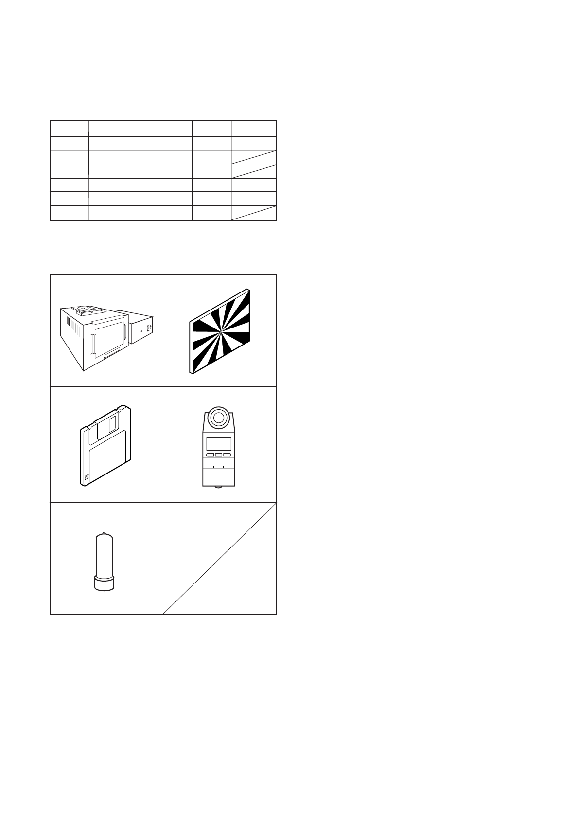
[1] Table for Servicing Tools
Ref. No.
J-1
J-2
J-3
J-4
J-5
J-6
Note: J-1 color viewer is 100 ± 10 VAC only.
Pattern box (color viewer)
Siemens star chart
Calibration software
Chroma meter
Spare lamp
Collimator
Use J-7 collimator made by Kyoritsu Electric Co. Ltd.
or equivalent of it.
Name Part code
Number
1
1
1
1
1
1
J-1 J-2
J-3
J-4
KC0336
KC0337
KC0339
5. CCD White Point Defect Detect Adjustment
6. CCD Black And White Point Defect Detect Adjustment in
Lighted
7. LCD Panel Adjustment
7-1. LCD H AFC Adjustment
7-2. LCD RGB Offset Adjustment
7-3. LCD Gain Adjustment
7-4. LCD Red Brightness Adjustment
7-5. LCD Blue Brightness Adjustment
8. EVF Adjustment
8-1. EVF H AFC Adjustment
8-2. EVF RGB Offset Adjustment
8-3. EVF Gain Adjustment
8-4. EVF Red Brightness Adjustment
8-5. EVF Blue Brightness Adjustment
Note:
1. If the lens, CCD, board and changing the part in item 2-
6 replace, it is necessary to adjust again. Item 3 should
be carried out after item 2. Item 5 and 6 should be carried out after item 4.
[4] Setup
1. System requirements
Windows 98 or Me or 2000 or XP
IBM ®-compatible PC with pentium processor
CD-ROM drive, 3.5-inch high-density diskette drive
USB port, 40 MB RAM
Hard disk drive with at least 15 MB available
VGA or SVGA monitor with at least 256-color display
J-5
[2] Equipment
1. Oscilloscope
2. Digital voltmeter
3. AC adaptor
4. PC (IBM ®-compatible PC, Pentium processor, Windows
98 or Me or 2000 or XP)
[3] Adjustment Items and Order
1. IC501 Oscillation Frequency Adjustment
2. Lens Adjustment
3. Lens Infinity Adjustment
4. AWB Adjustment
2. Installing calibration software
1. Insert the calibration software installation diskette into
your diskette drive.
2. Open Explorer.
3. Copy the DscCalDI_130c folder on the floppy disk in the
FD drive to a folder on the hard disk.
3. Installing USB driver
Install the USB driver with camera or connection kit for PC.
4. Pattern box (color viewer)
Turn on the switch and wait for 30 minutes for aging to take
place before using Color Pure. It is used after adjusting the
chroma meter (KC0337) adjust color temperature to 3100
± 20 K and luminosity to 900 ± 20 cd/m
dling the lamp and its circumference are high temperature
during use and after power off for a while.
C-2 Ver. 1
2
. Be careful of han-
Page 3
C. ADJUSTMENT METHODC-760Ultra Zoom
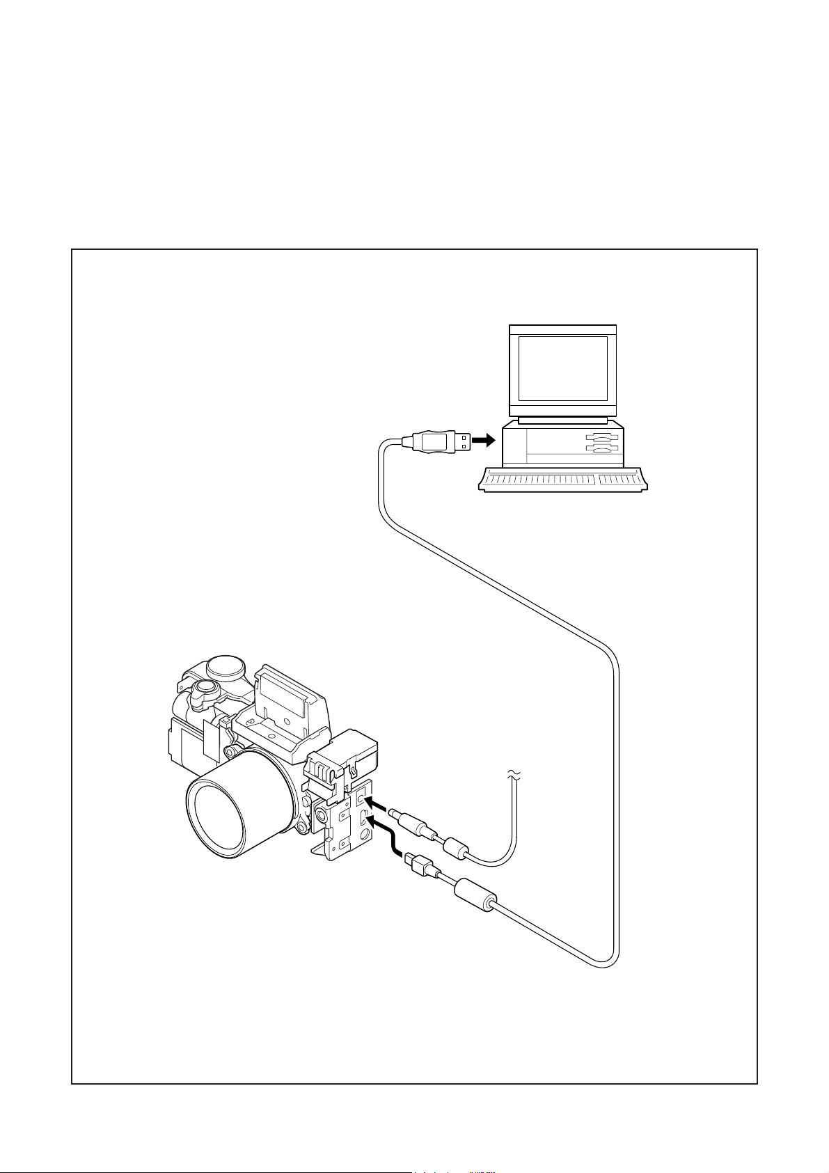
[5] Connecting the camera to the computer
* Since a switch and LCD are attached to Back cover, arrange connecting FPC and a lead line according to the contents of
adjustment etc.
1. Insert the xD card.
2. Line up the arrow on the cable connector with the notch on the camera's USB port. Insert the connector.
3. Locate a USB port on your computer.
To USB port
AC adaptor
USB cable
C-3 Ver. 1
Page 4

C. ADJUSTMENT METHOD
C-760Ultra Zoom
[6] USB Storage Information Registration
USB storage data is important for when the camera is connected to a computer via a USB connection.
If there are any errors in the USB storage data, or if it has
not been saved, the USB specification conditions will not be
satisfied, so always check and save the USB storage data.
Preparation:
POWER switch: ON
Adjustment method:
1. Connect the camera to a computer. (Refer to [5] Connecting the camera to the computer on the page C-3.)
2. Double-click on the DscCalDi.exe in the DscCalDi131.
3. Click on the Get button in the USB storage window and
check the USB storage data.
VID: OLYMPUS
PID: C760UZ
Serial:
Rev. : 1.00
4. Check the “Serial” in the above USB storage data. If the
displayed value is different from the serial number printed
on the base of the camera, enter the number on the base
of the camera. Then click the Set button.
5. Next, check VID, PID and Rev. entries in the USB storage data. If any of them are different from the values in
3. above, make the changes and then click the corresponding Set button.
Calibration
AWB
Focus
UV Matrix
Cal Mode
Cal Data
USB storage
VID
Get
PID
Set
Backrush pulse :
OK
OK
Upload
Firmware
Image
Initialize
EVF
LCD Type
Get
* Although it is mentioned "Click DSC CAL. EXE" (ad-
justment software starting) at each adjustment step, con-
tinuation of every adjustment is also possible.
LCD
R Bright
RGB Offset
Tint
VCO
H AFC Test
Serial
Set
Set
Rev.
B Bright
Gain
Phase
Set
Set
Set
VCOMDC
VCOMPP
Setting
Language
Video Mode
[7] Adjustment Specification
1. Lens Adjustment
Camera
Approx.
150 cm ± 3 cm
Siemens
star chart
Setting the adjustment mode(Before connecting to
the PC)
1. Open the card cover of the camera.
2. Turn on the power switch. ”CARD-COVER OPEN” will be
displayed in the EVF or LCD.
3. Push the LCD button and OK button more than 3 seconds simultaneously.
4. Push the right arrow button, and select “STORAGE”.
5. “STORAGE/CONTROL” will be displayed.
6. Push the below arrow button, and select “CONTROL”.
7. Push the OK button.
8. Close the card cover of the camera.
Preparation:
POWER switch: ON
Adjustment condition:
Siemens star chart (A3)
Fluorescent light illumination with no flicker (incandescent
light cannot be used.)
Illumination above the subject should be 700 lux ± 10%.
Adjustment method:
1. Set the siemens star chart 150 cm ± 3 cm so that it becomes center of the screen.
2. Double-click on the DscCalDi.exe.
3. Click the “Focus”, and Click the “Yes”.
4. Lens adjustment value will appear on the screen.
(When adjustment is failed, “STD_AFPOS=0” will display.)
5. Click the OK.
C-4 Ver. 1
Page 5

C. ADJUSTMENT METHODC-760Ultra Zoom
2. Lens Infinity Adjustment
Camera
Collimator
(Set up to the infinty.)
Preparation:
POWER switch: ON
Set up the collimator to the infinity.
Note:
Do not vibrate during the adjustment.
Adjustment method:
1. Set the camera so that it becomes center of the siemens
star chart in the collimator.
2. Double-click on the DscCalDi.exe.
3. Select “Infinity Cal.” on the LCD “Test”, and click the “Yes”.
4. Lens infinity adjustment value will appear on the screen.
(When adjustment is failed, “lens_inf_ng” will display.)
5. Click the OK.
Preparation:
POWER switch: ON
Setting of pattern box:
Color temperature: 3100 ± 20 (K)
Luminance: 900 ± 20 (cd/m
2
)
Adjusting method:
1. Set the camera 0 cm from the pattern box. (Do not enter
any light.)
2. Double-click on the DscCalDi.exe.
3. Click the “AWB”, and click the “Yes”.
4. AWB adjustment value will appear on the screen.
5. Click the OK.
Adjustment value determination is effectuated using "AGC"
and "CHECK" values.
If AGC=a1, a2, a3, a4, CHECK=wc0, wc1, wc2 and the adjustment values fulfill the conditions below (neglect the AGC
value of a5 even though you will see it on the monitor), they
are determined as within specifications.
Adjustment value determination
a1<1023, a2<1023, a3<1023, a4<1023
(neglect the AGC value of a5 even though you will see it on
the monitor)
wc0=128 ± 2, wc1=128 ± 2, wc2=130 ± 40
4. CCD White Point Defect Detect Adjustment
Preparation:
POWER switch: ON
Adjustment method:
1. Double-click on the DscCalDi.exe.
2. Select “CCD Defect” on the LCD “Test”, and click the
“Yes”.
3. After the adjustment is completed, the number of defect
3. AWB Adjustment
Camera
Pattern box
(color viewer)
C-5 Ver. 1
Page 6

C. ADJUSTMENT METHOD
C-760Ultra Zoom
5. CCD Black And White Point Defect Detect
Adjustment In Lighted
Camera
Pattern box
(color viewer)
Preparation:
POWER switch: ON
Setting of pattern box:
Color temperature: 3100 ± 20 (K)
Luminance: 900 ± 20 (cd/m
Adjusting method:
1. Set the camera 0 cm from the pattern box. (Do not enter
any light.)
2. Double-click on the DscCalDi.exe.
3. Select “CCD Black” on the LCD “Test”, and click the “Yes”.
4. After the adjustment is completed, the number of defect
will appear.
(When adjustment is failed, “detect_ng BLACK x, y” will
display.)
5. Click the OK.
2
)
6-1. LCD H AFC Adjustment
Preparation:
POWER switch: ON
Adjusting method:
1. Double-click on the DscCalDi.exe.
2. Select 0 on the LCD “H AFC”.
3. Apply a trigger using CL427, and adjust LCD “H AFC” so
that the time A from the rising signal at CL427 to the rising signal at CL424 is 2.25 ± 0.15 µsec.
○○○○○○○○
○○
A
CL424
CL427
Enlargement
○○○○○○○○
○○
A
CL424
CL427
6-2. LCD RGB Offset Adjustment
Adjusting method:
1. Adjust LCD “RGB Offset” so that the amplitude of the
CL421 waveform is 4.5 V ± 0.1 Vp-p.
6. LCD Panel Adjustment
[CP1 board (Side B)]
CL421(G)
CN424
(EN_ME)
CL423(B)
CL422(R)
CL427(CSYNC)
4.5 V ±
0.1 Vp-p
CL421 waveform
6-3. LCD Gain Adjustment
Adjusting method:
1. Adjust LCD “Gain” so that the amplitude of the CL421
waveform is 7.6 V ± 0.2 Vp-p.
Note:
6-2. LCD RGB Offset adjustment should always be carried
out first.
C-6 Ver. 1
Page 7

C. ADJUSTMENT METHODC-760Ultra Zoom
7.6 V ±
0.2 Vp-p
VG
CL421 waveform
6-4. LCD Red Brightness Adjustment
Adjusting method:
1. Adjust LCD “R Bright” so that the amplitude of the CL422
waveform is (VG-0.1) ± 0.1 Vp-p with respect to the
CL421(VG) waveform.
Note:
6-2. LCD RGB Offset adjustment and 6-3. LCD Gain adjustment should always be carried out first.
VG
CL421 waveform
CL421 waveform
(VG + 0.05)
± 0.1Vp-p
CL423 waveform
7. EVF Adjustment
7-1. EVF H AFC Adjustment
Preparation:
POWER switch: ON
Adjusting method:
1. Double-click on the DscCalDi.exe.
2. Click the check box at the “EVF”.
3. Select 0 on the EVF “H AFC”.
4. Apply a trigger using CL427, and adjust EVF “H AFC” so
that the time E from the rising signal at CL427 to the rising signal at CL424 is 3.25 ± 0.15 µsec.
○○○○○○○○
○○
E
CL424
(VGÐ0.1) ±
0.1 Vp-p
CL422 waveform
6-5. LCD Blue Brightness Adjustment
Adjusting method:
1. Adjust LCD “B Bright” so that the amplitude of the CL423
waveform is (VG+0.05) ± 0.1 Vp-p with respect to the
CL421 (VG) waveform.
Note:
7-2. LCD RGB Offset adjustment and 6-3. LCD Gain adjustment have done.
CL427
Enlargement
○○○○○○○○
○○
E
CL424
CL427
7-2. EVF RGB Offset Adjustment
Adjusting method:
1. Adjust EVF “RGB Offset” so that the amplitude of the
CL421 waveform is 4.4 V ± 0.1 Vp-p.
C-7 Ver. 1
Page 8

C. ADJUSTMENT METHOD
4.4 V ±
0.1 Vp-p
CL421 waveform
7-3. EVF Gain Adjustment
Adjusting method:
1. Adjust EVF “Gain” so that the amplitude of theCL421
waveform is 7.5 V ± 0.2 Vp-p.
Note:
7-2. EVF RGB Offset adjustment should always be carried
out first.
C-760Ultra Zoom
7-5. EVF Blue Brightness Adjustment
Adjusting method:
1. Adjust EVF “B Bright” so that the amplitude of the CL423
waveform is (VG + 0.05) ± 0.1 Vp-p with respect to the
CL421 (VG) waveform.
Note:
7-2. EVF RGB Offset adjustment and 7-3. EVF Gain adjustment have done.
VG
CL421 waveform
7.5 V ±
0.2 Vp-p
CL421 waveform
7-4. EVF Red Brightness Adjustment
Adjusting method:
1. Adjust EVF ”R Bright” so that the amplitude of the CL422
waveform is (VG-0.1) ± 0.1 Vp-p with respect to the
CL421 (VG) waveform.
Note:
7-2. EVF RGB Offset adjustment and 7-3. EVF Gain adjustment should always be carried out first.
VG
(VG + 0.05)
± 0.1 Vp-p
CL423 waveform
8. Closing the adjustment mode
1. Open the card cover of the camera.
2. Turn on the power switch. “CARD-COVER OPEN” will be
displayed in the EVF or LCD.
3. Push the LCD button and OK button more than 3 seconds simultaneously.
4. Push the right arrow button, and select “CONTROL”.
5. “STORAGE/CONTROL” will be displayed.
6. Push the below arrow button, and select “STORAGE”.
7. Push the OK button.
8. Close the card cover of the camera.
CL421 waveform
CL422 waveform
(VGÐ0.1) ±
0.1 Vp-p
C-8 Ver. 1
Page 9

9. Adjustment Items
C. ADJUSTMENT METHODC-760Ultra Zoom
Adjustment items
䇭䇭
1. Lens Adjustment
2. Lens Infinity Adjustment
3. AWB Adjustment
4. CCD White Point Defect Detect Adjustment
5. CCD Black Point and White Point Defect Detect Adjustment in Lighted
6. LCD Panal Adjustment - - -
7. EVF Adjustment - - -
Lens CCD LPF CP-1
Changed repaire parts
C-9 Ver. 1
Page 10

 Loading...