

Page 1

C-2500L
B. DISASSEMBLY AND ASSEMBLY PROCEDURE
[ 1 ] Flowchart of DISASSEMBLY AND ASSEMBLY...................... B-2
[ 2 ] Disassembly and assembly procedure................................... B-3
1. Rear Cover G#-2............................................................................. B-4
2. Front Cover G# ............................................................................... B-5
3. Upper Cover G#-3, Grip #...............................................................B-6
4. SW FPC G#-3 .................................................................................. B-8
5. Main G#-2 ........................................................................................ B-9
6. Lens-CCD Unit , Battery Case G#-2 ............................................. B-11
SERVER_DIS B-1 Ver.1.0
Page 2

[ 1 ] Flowchart
B.DISASSEMBLY AND ASSEMBLY PROCEDURE C-2500L
C-2500L
Rear Cover
G#-2
Logo Plate
Lens Under
Cover
Front Cover
G#
Grip#
Upper
Cover G#-2
09PW-PCA
SW FPC
G#-3
Main G#-2
Lens-CCD
Unit
Battery
Case G#-2
SW FPC
G#-3
09PW-PCA
Battery
Case G#-2
SERVER_DIS B-2 Ver.1.0
ST C.B.A.
G#-2
Page 3

C-2500L B.DISASSEMBLY AND ASSEMBLY PROCEDURE
[ 2 ] Disassembly and assembly procedure
Disassembly : Disassemble as follow(1, 2 , ---).
Assembly : Reversing the disassembly, Assemble (---, 2 , 1).
Ver.1.0 B-3 SERVER_DIS
Page 4
B.DISASSEMBLY AND ASSEMBLY PROCEDURE C-2500L
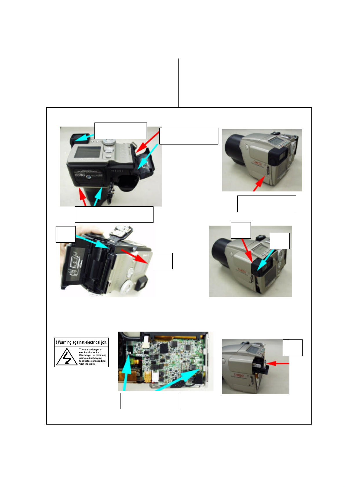
1. Rear Cover G#-2
[Note: when disassembling]
1) (5)(6)
Remove Rear Cover G#-2 in the direction of (6)
with pressing lightly CF eject lever (5). (Fig-3)
Fig-1
(2)PUK1.6x9SB
(3)PUTB1.6x3.5SB
Fig-3
(5)
[Note: when assembling]
1)Install 5T Frame# in the direction of (9),
set the Diopter Dear portion downward.
2) First, assemble Rear Cover from finder (4)
3) Attention! Posiotion of eject lever.
Fig-2
(1)PUTB1.6x3.5SB
(4)PUK2x4.5SN
Fig-4
(7)
(10)
Fig-5
(6)
Fig-6
(9)
(8)Discharge points
SERVER_DIS B-4 Ver.1.0
Page 5

C-2500L B.DISASSEMBLY AND ASSEMBLY PROCEDURE
2.Front Cover G#
[Note: when disassembling] [Note: when assembling]
1) (6): The patern side of FPC is back side.
Fig-7
(1)3PUTB1.6x4SN
Fig-9
(2)
(5)PUTB1.6x3.5SB
(5)PUTB1.6x3.5SB
Fig-8
(3)
(1)3PUTB1.6x4SN
(4)
Fig-10
(6) (7)
(5)PUTB1.6x3.5SB
[Disassembly and assembly for Front Ring]
Fig2-a
(2)
(1)PUTB1.6x4SB
(3) Turn it un-clockwise
Ver.1.0 B-5 SERVER_DIS
Page 6

B.DISASSEMBLY AND ASSEMBLY PROCEDURE C-2500L
4.Upper Cover G#-3, Grip #
[Note: when disassembling]
1) (1) Four screws
2) (10) : Remove Grip# from (7).
Fig-11
(2) X Holder
(1)PSTB1.6x6SG
[Note: when assembling]
1)Harness of Upper Cover#-3 (Fig-15).
Fig-12
(5)PUTB1.6x4SB
(6)PUTB1.6x9SN
(3)PUK2x4.5SN
(5)PUTB1.6x4
SB
(4)PUK1.6-235SN
Fig-13
Fig-14
(12)DC
CONNECT NW
(9) Lift-up
(8) Pop-up
(10)
(7)PUTB1.6-430SH
Fig-15
(11)PUTB1.6-630SN
(14)
(13) Connector
SERVER_DIS B-6 Ver.1.0
Page 7

C-2500L B.DISASSEMBLY AND ASSEMBLY PROCEDURE
[Assembly for Z Spring G]
1)Adhesive applying area
Area is much more than 2mm via part of bend from the point.
2)Positon (Fig-3-a)
Set Z Spring G inside projections.
Fig-3-A
Projection
Projection
[Assembly for Grip Rabber]
Adhesive is Super X (Black)
The position is refer to Fig-3-b.
0 to 2mm
0 to 2mm
[Disassembly for Grip Rabber]
Remove STSW1G and STSW2G after (2).
Fig-3-c, Fig-3-d.
Fig-3-c
Fig-3-b
Super X
Fig-3-d
(3)
(1) 3PUTB1.6x3.5SN
(1) 3PUTB1.6x3.5SN
(2) 09ST-FPCB
Ver.1.0 B-7 SERVER_DIS
(4)
Page 8

B.DISASSEMBLY AND ASSEMBLY PROCEDURE C-2500L
4.SW FPC G#-3
[Note: when disassembling] [Note: when assembling]
1)Position for double side of adhesive tape
Fig-19: Control panel
Fig-20: TFT monitor
2)Insert the thermistor of battery into hole of battery (Fig-21)
Fig-16
Fig-18
Fig-17
(4) D CONTACT 2
(3)PUTB1.6-430SB
(1)PUTB16-430SB(2)
Fig-19 Fig-20
(5) Connector
Fig-21
Hole
SERVER_DIS B-8 Ver.1.0
Battery thermistor
Page 9

C-2500L B.DISASSEMBLY AND ASSEMBLY PROCEDURE
5.Main G#-2
[Note: when disassembling]
1)There is interferrence between SW base(9) and
LED base(10).(Fig-26)
Fig-22
(2)Dis-soder
(1)PW
Sponge
(2)Dis-soder
Fig-24
[Note: when assembling]
1)The hook of B2B Holder should be situated
under 09MC-PCB(Fig-27)
Fig-23
(3)PUK1.6-425SN
(3)PUK1.6-425SN
(4)
Fig-25
(7)
(6)PUK1.6x2.5SN
(5)
Fig-26 Fig-27
(9)(10)
(8)PUK1.6-235SN
(11)3PUTB1.6x3.5SN
(14)
(13)
Hook
(12)3PUTB1.6x11.5SN
Ver.1.0 B-9 SERVER_DIS
Page 10

B.DISASSEMBLY AND ASSEMBLY PROCEDURE C-2500L
[Note: assembly forTFT Cover]
Main G#-2 doesn’t contain TFT Cover
Don’t forget to attach TFT Cover after chenging Main G#-2.
(Fig-6-a)
Fig-6-a
TFT Cover
SERVER_DIS B-10 Ver.1.0
Page 11

C-2500L B.DISASSEMBLY AND ASSEMBLY PROCEDURE
6. Lens-CCD Unit , Battery Case G#-2
Fig-28
(1)PUTB1.6x3.5SB
Ver.1.0 B-11 SERVER_DIS
 Loading...