


IP Camera with Receiver
IC 1285 Z
…easy to operate using the
"ProHomeIPC" app from Olympia
Operating Manual
11.2016 en


Contents
Contents
General Information . . . . . . . . . . . . |
6 |
General Safety Information . . . . . . . . |
6 |
Intended Use . . . . . . . . . . . . . . . . . . . . |
7 |
Unintended Use . . . . . . . . . . . . . . . . . |
7 |
Legal Notice . . . . . . . . . . . . . . . . . . . . |
7 |
Notations Used in this Manual . . . . . |
7 |
System Requirements . . . . . . . . . . . . |
8 |
iOS . . . . . . . . . . . . . . . . . . . . . . . . . . . . . . . . . |
8 |
Android . . . . . . . . . . . . . . . . . . . . . . . . . . . . . . |
8 |
General Overview . . . . . . . . . . . . . . . |
9 |
Checking the Package Contents . . . |
9 |
Connections and Operating Elements |
9 |
Receiver . . . . . . . . . . . . . . . . . . . . . . . |
11 |
Pivoting Range and Angle of Vision |
11 |
Connecting the Camera . . . . . . . . . 12
Inserting the MicroSD Memory Card 12
Positioning the Camera . . . . . . . . . . . 12
Mounting the Camera on the
Wall/Ceiling . . . . . . . . . . . . . . . . . . 12
Connecting the Camera -
Network Cable . . . . . . . . . . . . . . . . 13
Connecting the Camera -
Power Adapter and Receiver . . . 13
Operating with an Alarm System
(Protect 6xxx / 9xxx) . . . . . . . . . . . . . . . 13
Registering the Receiver on the
Alarm System . . . . . . . . . . . . . . . . 14 Use Without an Alarm System . . . . . 16 Installing the ProHomeIPC App . . . . 17
G |
3 |

Contents
Connecting the Smartphone/Tablet PC
to the Camera . . . . . . . . . . . . . . . 18
Using the ProHomeIPC App . . . . . 20
Operating the Camera (iOS) . . . . . 22
Moving the Screen Section . . . . . . . . 22 Opening the Menu Bar . . . . . . . . . . . 22 Buttons in the Menu Bar . . . . . . . . . . 23
Push to Talk . . . . . . . . . . . . . . . . . . . . . . . . . . 23 Snapshots . . . . . . . . . . . . . . . . . . . . . . . . . . . 23 Saving Image Sections as a Preset . . . . . . 24 Activating Night Vision . . . . . . . . . . . . . . . . . 25 Flipping the Image Section Horizontally . . 25 Flipping the Image Section Vertically . . . . 26 Changing the Resolution . . . . . . . . . . . . . . . 26 Adapting to Environmental Conditions . . . 26
Start Screen of the ProHomeIPC App 27
Context Menu of the
ProHomeIPC App . . . . . . . . . . . . . 28
Camera List . . . . . . . . . . . . . . . . . . . . . 29
Event . . . . . . . . . . . . . . . . . . . . . . . . . . 30
Add Device . . . . . . . . . . . . . . . . . . . . . 31
QR Code . . . . . . . . . . . . . . . . . . . . . . . . . . . . 32
Automatic Search . . . . . . . . . . . . . . . . . . . . . 33
Connecting Manually . . . . . . . . . . . . . . . . . . 34
Version Information . . . . . . . . . . . . . . 35
Deleting Cameras . . . . . . . . . . . . . . . 36
Settings . . . . . . . . . . . . . . . . . . . . . . . . 37
Camera . . . . . . . . . . . . . . . . . . . . . . . . . . . . . . 38
Advanced Settings . . . . . . . . . . . . . . . 42
Alarm Setting . . . . . . . . . . . . . . . . . . . 47
Time Setting . . . . . . . . . . . . . . . . . . . . 54
4 |
G |

Contents
Operating the Camera (Android) . |
55 |
Moving the Screen Section . . . . . . . . |
55 |
Opening the Menu Bar . . . . . . . . . . . |
55 |
Buttons in the Menu Bar . . . . . . . . . . |
56 |
Push to Talk . . . . . . . . . . . . . . . . . . . . . . . . . . |
56 |
Snapshots . . . . . . . . . . . . . . . . . . . . . . . . . . . |
56 |
Saving Image Sections as a Preset . . . . . . |
57 |
Activating Night Vision . . . . . . . . . . . . . . . . . |
58 |
Flipping the Image Section Horizontally . . |
58 |
Flipping the Image Section Vertically . . . . |
59 |
Changing the Resolution . . . . . . . . . . . . . . . |
59 |
Adapting to Environmental Conditions . . . |
59 |
Start Screen of the ProHomeIPC App |
60 |
Add Device . . . . . . . . . . . . . . . . . . . . . |
61 |
QR Code . . . . . . . . . . . . . . . . . . . . . . . . . . . . |
62 |
Automatic Search . . . . . . . . . . . . . . . . . . . . . |
63 |
Connecting Manually . . . . . . . . . . . . . . . . . . |
64 |
Context Menu of the Camera . . . . . . |
65 |
Reconnect . . . . . . . . . . . . . . . . . . . . . . . . . . . |
66 |
|
G |
View Event . . . . . . . . . . . . . . . . . . . . . . . . . . . 67
View Snapshot . . . . . . . . . . . . . . . . . . . . . . . 68
Remove Camera . . . . . . . . . . . . . . . . . . . . . . 69
Edit Camera . . . . . . . . . . . . . . . . . . . . . . . . . . 70
Edit Camera . . . . . . . . . . . . . . . . . . . . |
71 |
Device Setting . . . . . . . . . . . . . . . . . . . . . . . . 72
Advanced Setting . . . . . . . . . . . . . . . . 76
Alarm Setting . . . . . . . . . . . . . . . . . . . 80
Time Setting . . . . . . . . . . . . . . . . . . . . 87
Other Important Information . . . . . 88
Guarantee . . . . . . . . . . . . . . . . . . . . . . 88 Regular Maintenance and Service . 88 Technical Modifications . . . . . . . . . . . 88 Information on Disposal . . . . . . . . . . 88 CE Mark . . . . . . . . . . . . . . . . . . . . . . . . 88 Technical Data . . . . . . . . . . . . . . . . . . 89 Troubleshooting . . . . . . . . . . . . . . . . . 90
5

General Information
General Safety Information
General Information
Please read and observe the following information and keep this operating
manual in a safe place for future reference!
General Safety Information
Observe the following safety instructions in order to pro tect yourself from the possibility of personal injury and the product from damage.
WARNING!
•Risk of electric shock! Never attempt to open and re pair the device or accessories yourself. Never touch bare contacts with metallic objects. Never plug-in or un plug the power cable when your hands are wet.
•Risk of suffocation! Keep out of reach of children!
Keep packaging materials and protective foils out of reach of children. Keep the device and any accessories out of reach of children. Small children can swallow small parts. Seek medical attention immediately if a small part is swallowed.
CAUTION!
•Risk of hearing damage! The audio signals are emit ted through a loudspeaker. Pay attention that a reason able loudspeaker volume is set for transmitting the audio signals.
ATTENTION!
Avoid the risk of property damage to your device and ob serve the information!
•Do not use the camera in prohibited areas! Prohibit ed areas could include public buildings or spaces, for example. Please observe local laws and regulations!
•Protect the camera from moisture, dust, liquids, chemi cals, vapours, heat and direct sunlight. The camera is not waterproof, so ensure you keep it dry.
•Only use original accessories. Only connect acces sories approved by the manufacturer to the camera and only us the power adapter supplied.
•Property damage is possible. Only use properly in stalled, easily accessible power sockets.
•Repairs to this device may only be completed by prop erly qualified service personnel.
6 |
G |

General Information
Intended Use and Notations Used in this Manual
Intended Use
The IP camera (subsequently referred to as the camera) is designed to perform video surveillance (CCTV) by day and night. The camera is exclusively intended for use in closed rooms. When installing and selecting the area of application of the camera, pay attention to the personal rights of third-parties and that the respective, applicable local laws and regulations are not violated.
Unintended Use
The camera is not suitable for use in wet rooms or poten tially explosive areas.
Monitoring of third-parties is not permitted without the re spective, explicit authorisation and could have legal con sequences.
Any use other than that described in Intended Use is con sidered unintended use. Unauthorised modification
or reconstruction is not permitted.
Under no circumstances open the camera or accessories or attempt to complete any repair work yourself.
Legal Notice
All the trademarks or brand names on the product and/or accessories or which appear in this operating manual serve solely for descriptive purposes and do not imply that they are freely available. The trademarks and brand names are the property of the respective proprietor of the rights.
Notations Used in this Manual
The section below explains the presentations and nota tions used in this operating manual.
1.This indicates the first step in a set of instructions.
2.This indicates the next step in a set of instructions.
This symbol indicates useful information which will help you to use the camera and ProHomeIPC App.
Indicates a list.
G |
7 |

General Information
System Requirements
System Requirements
This operating manual assumes users have a basic knowledge of connecting and configuring network-capable devices and smartphones or tablet PCs.
iOS
In order to exploit the full functional scope of the camera using the ProHomeIPC App for iOS, you require:
an internet-capable iPhone (from iPhone 4)
operating system iOS 7 or later
ProHomeIPC App
(refer to Chapter Installing the ProHomeIPC App)
Android
In order to exploit the full functional scope of the camera using the ProHomeIPC App for Android, you require:
an internet-capable smartphone
operating system Android 4.0 or later
ProHomeIPC App
(refer to Chapter Installing the ProHomeIPC App)
8 |
G |

General Overview
This section provides information on the package contents as well as the connections and operating elements on the camera.
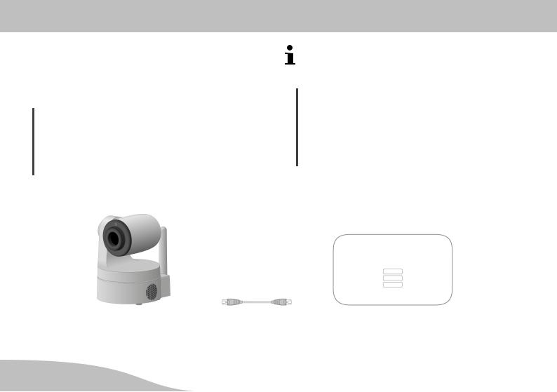
Checking the Package Contents
Unpack the camera and check that the package contents are complete. The camera package must contain the fol lowing components:
Camera
Power adapter plug
Receiver
Mounting bracket
Network cable (RJ45/RJ45, Cat.5e)
Operating manual
Check for any visible signs of damage to the camera packaging or the components supplied. If there are, do not put the camera into operation.
General Overview
Checking the Package Contents
Connections and Operating Elements
Before connecting the camera, familiarise yourself with the connections and operating elements on it.
1Brightness sensor
2Microphone
3Infrared LEDs (night vision)
4 Lens with optical zoom
5WLAN receiving antenna
6Loudspeaker
7Power adapter connection port
8Port for receiver
(connection to an alarm system from the Protect series)
9MicroSD card slot (max. 32 GB)
10Network connection port
11Aux output (3.5 mm connector)
12Internal thread for mounting bracket
13Rating plate with QR code
14Reset button
G |
9 |

General Overview
Connections and Operating Elements
10 |
G |
General Overview
Receiver
Receiver |
Pivoting Range and Angle of Vision |
15Power cable (connect to power connection port on the camera)
16Power adapter connection port
17I/O port
18Status LED (not illustrated here)
A Vertical pivoting range
B Horizontal pivoting range
CAngle of vision
G |
11 |

Connecting the Camera
Inserting the MicroSD, Positioning or Mounting the Camera
Connecting the Camera
This section provides information on how to position and connect the camera and insert a microSD memory card in it.
Inserting a microSD memory card
Positioning the camera or mounting it on a wall
Connecting the camera - network cable
Connecting the camera - power adapter and receiver
Positioning the Camera
When the camera is put into operation for the first time, it must be connected to a network connection port (LAN) on your router via the network cable. Therefore, when putting the camera into operation for the first time, it should be located near your router.
After putting the camera into operation for the first time and configuring it, you can install the camera at the lo cation where it should perform the video surveillance.
When doing so, it is essential to observe the applicable laws and local regulations.
Inserting the MicroSD Memory Card
In order to be able to make video recordings and save them, you must insert a microSD memory card in the camera. Use a microSD memory card with a maximum memory capacity of 32 GB.
No microSD memory card is enclosed in the camera package supplied.
1.Insert a microSD memory card in the microSD memory card slot at the rear of the camera.
The microSD memory card latches audibly in place.
Mounting the Camera on the
Wall/Ceiling
You can mount the camera anywhere using the mounting bracket contained in the package supplied.
WARNING!
Risk of fatal injury through electric shock or gas ex plosion!
During installation, pay attention to the possibility of electrical cables and gas pipes running in the walls.
Pay attention that you do not damage electric cables or gas pipes.
12 |
G |

1. Drill two sufficiently large holes in the wall.
Use the mounting bracket supplied as the template for the position of the holes.
2.Insert the dowels in the drill holes.
3.Assemble the mounting bracket using suitable screws.
4.Fit the camera on the mounting bracket.
Use the internal thread on the underside of the cam era.
Connecting the Camera -
Network Cable
Connect the network cable to the network connection port (10) on the camera and a free network connection port (LAN) on the router.
A condition for putting into operation is the unam biguous identification of your camera within your net work. If you have not altered the default setting of your router, this will occur automatically. In the case of most routers, the DHCP function is activated at the factory.
Connecting the Camera
Connecting the Camera -
More detailed information on the DHCP function is provided in the operating manual supplied with your router.
Connecting the Camera -
Power Adapter and Receiver
If you want to integrate the camera in an existing alarm system, you need the receiver supplied.
If you only want to use the camera to monitor a certain area, you do not need the receiver supplied.
Operating with an Alarm System (Protect 6xxx / 9xxx)
If you want to integrate the camera in an alarm system
(Protect Series 6xxx / 9xxx alarm system from Olympia), you must use the receiver supplied.
1. Connect the receiver to the port (8) on the camera.
ATTENTION!
Property damage is possible!
The camera could be damaged if you use a wrong power adapter.
Only use the power adapter supplied.
2.Connect the power cable (16) on the receiver to the power connection port (7) on the camera.
G |
13 |

Connecting the Camera
Registering the Receiver on the Alarm System
3.Connect the power adapter to the power connection port (17) on the receiver and a properly installed, easily accessible power socket.
The LEDs on the network connection port (10) signal when a connection exists to the network (lights up orange) and that data is being transmitted (flashes green).
ATTENTION!
Property damage is possible!
The camera could be damaged if you move the ser vomotors by hand or interrupt the movement.
Avoid moving the servomotors by hand or interrupt ing the movement of the camera.
4.The servomotors of the camera are controlled automati cally. Wait until the process has finished.
Registering the Receiver on the Alarm System
After connecting the power supply and network to the re ceiver, you must register the receiver on the base unit of the alarm system.
1.Disconnect the power cable of the camera from the power socket on the receiver.
2.Select the Register menu option on the alarm system.
To configure the alarm system, please refer to the manual supplied with the alarm system.
3.Connect the power cable of the camera to the power socket on the receiver.
4.When the message Siren followed by a number ap pears in the alarm system display, registration on the alarm system was completed successfully.
Change the Siren entry to Camera, for example, us ing the alarm system menu.
5.The receiver is now registered on the alarm system and can receive signals from the alarm system. In the event of an alarm, the red LED (19) on the rear of the receiver indicates that an active connection between the alarm system and receiver exists.
14 |
G |

Connecting the Camera
Registering the Receiver on the Alarm System
Communication |
Alarm System |
Camera + Sensor |
Network Cable |
Router |
G |
15 |
Connecting the Camera
Use Without an Alarm System
Use Without an Alarm System
If you want to use the camera without an alarm system (Protect Series 6xxx / 9xxx alarm system from Olympia), you do not need the receiver supplied.
ATTENTION!
Property damage is possible!
The camera could be damaged if you use a wrong power adapter.
Only use the power adapter supplied.
1.Connect the power cable to the power connection port (7) and a properly installed power socket.
The LEDs on the network connection port (10) signal when a connection exists to the network (lights up orange) and that data is being transmitted (flashes green).
ATTENTION!
Property damage is possible!
The camera could be damaged if you move the servomotors by hand or interrupt the movement.
Avoid moving the servomotors by hand or interrupt ing the movement of the camera.
2.The servomotors of the camera are controlled automati cally. Wait until the process has finished.
Camera |
Network Cable |
Router |
16 |
G |

Connecting the Camera
Installing the ProHomeIPC App
Installing the ProHomeIPC App
1.Download the ProHomeIPC App from the App Store or
Google Play Store.
2.Enable the ProHomeIPC App access to the camera of your smartphone or tablet PC and mobile internet. This simplifies connecting the camera and ProHomeIPC App and also enables remote access to the camera via the smartphone or tablet PC.
You require access to the camera on your smart phone or tablet PC when you want to scan the QR code as described in Section Connecting the
Smartphone/Tablet PC to the Camera.
Access to the camera and mobile internet can also be enabled or refused later in the setting options pro vided by your smartphone or tablet PC. More de tailed information is provided in the operating manual supplied with your smartphone or tablet PC.
G |
17 |
Connecting the Smartphone/Tablet PC to the Camera
Installing the ProHomeIPC App
Connecting the Smartphone/Tablet PC to the Camera
The following conditions must be fulfilled in order that you can use the camera:
You have downloaded and installed the ProHomeIPC
App as described in Section Installing the
ProHomeIPC App.
You have set-up and connected the camera as described in Section Connecting the Camera.
You smartphone or tablet PC is in the same network as the camera.
1.Start the ProHomeIPC App.
2.Touch Add Device or Click here to add camera.
3.Touch QRCode or Scan.
4.Scan the QR code on the rear of the camera using the smartphone or tablet PC.
18 |
G |
Connecting the Smartphone/Tablet PC to the Camera
Installing the ProHomeIPC App
The ProHomeIPC App automatically searches for all the cameras available in the network. If your smart phone or tablet PC is connected in the same network as the camera, the camera is displayed (together with the user identifier and IP address). Alternatively, touch the camera displayed.
5. Enter the camera's password (security code).
When the default settings are set, the password is admin.
6. Save the settings by touching Save or OK.
Your camera is now listed in the overview of cameras available.
The first time you attempt to select your camera, you will be requested to change the camera's password (security code) for reasons of security. We urgently recommend that you change the camera's password in order to prevent unauthorised access to your cam era, and thus your privacy, by third parties.
G |
19 |
Using the ProHomeIPC App
Installing the ProHomeIPC App
Using the ProHomeIPC App
Familiarise yourself with how to use the
ProHomeIPC App.
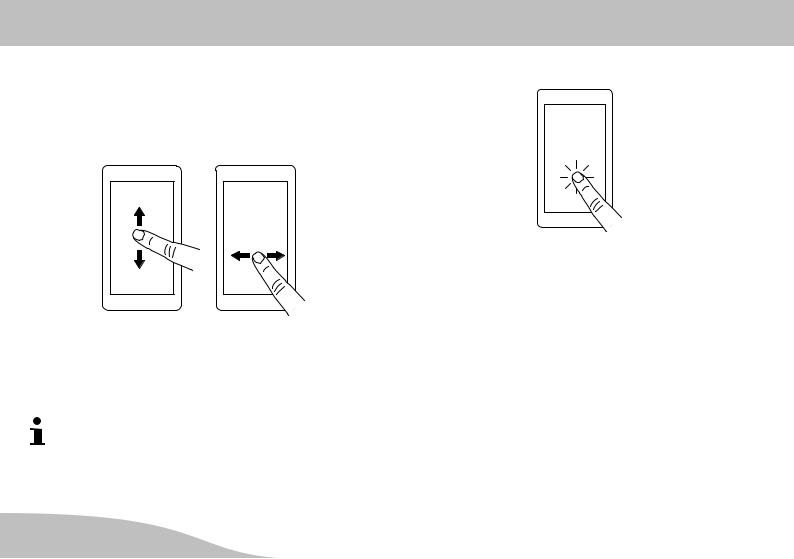
2. Tap your finger on the display of your smartphone or tablet PC to open the submenus and activate functions.
1.Swipe your finger in any direction over the display of your smartphones or tablet PC to move the screen sec tion displayed.
Alternatively, touch the green direction arrows to move the screen section displayed.
20 |
G |
Using the ProHomeIPC App
Installing the ProHomeIPC App
3.Zoom the image displayed on the display of your smart phone or tablet PC by touching the image section with two fingers and spreading them apart accordingly. Move your fingers in the opposite direction to reduce the size of the image.
Alternatively, touch the magnifying glass icons to zoom the image displayed in or out accordingly.
4.Rotate your smartphone or tablet PC on its side. The image then appears as a full screen display.
If necessary, you must activate the function to rotate the screen contents in the Settings menu on the smartphone or tablet PC. More detailed information is provided in the operating manual supplied with your smartphone or tablet PC.
G |
21 |
Operating the Camera (iOS)
Moving the Screen Section
Operating the Camera (iOS)
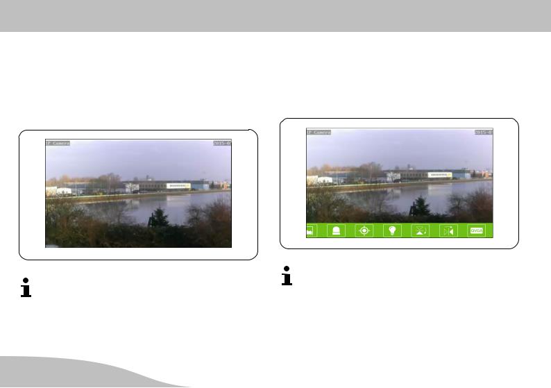
Moving the Screen Section
Swipe your finger in any direction over the display of your smartphone or tablet PC to move the screen section dis played.
There may be short delays before your camera re acts to the movement of your fingers on the screen of your smartphone or tablet PC depending on the signal strength.
Opening the Menu Bar
Touch your finger on the smartphone or tablet PC screen.
A menu bar opens at the bottom edge of the screen.
A function is assigned to each button in the menu bar. Touch one of the buttons to activate the function or, if necessary, define settings.
22 |
G |

Buttons in the Menu Bar
This section provides information on which functions are assigned to the buttons in the menu bar while a live pic ture is on screen and what you can do with them.
Push to Talk
The camera is equipped with a loudspeaker which can be used to issue vocal communication or sounds spoken or played in your smartphone or tablet PC.
1.Touch the Push-to-talk button.
2.Press and hold the button.
3.Speak into the microphone on your smartphone or tablet PC. The vocal communication entered is issued by the loudspeaker in the camera.
Operating the Camera (iOS)
Buttons in the Menu Bar
Snapshots
You can take a photo of the live image currently scanned by the camera.
1.Touch the Snapshot button. The live image currently displayed is saved as a snapshot. The Snapshot sa ved message appears in the display.
When the default settings are set, the snapshots are saved locally on the smartphone or tablet PC. You can also save your snapshots on the camera. More detailed information is provided in Section Record ing on the SD Memory Card.
2.Touch the button to open an overview of the snapshots taken.
G |
23 |
Operating the Camera (iOS)
Buttons in the Menu Bar
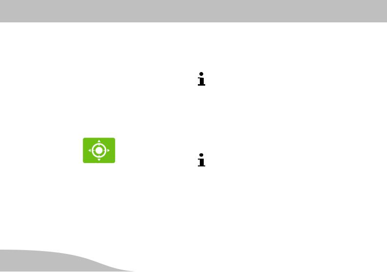
Saving Image Sections as a Preset
You can divide the image of the entire area under surveil lance (limited by the angle of detection and pivoting range of the camera) into different sections and save the sec tions individually as presets. A total of four presets are possible.
Each preset can then be assigned to a defined memory location
•to be accessed quickly.
•to display the respective area under surveillance. 1. Navigate to any section of the image.
2.Touch the Image section button.
3.Touch and hold one of the four memory locations (1 - 4) to assign the respective image preset. You receive a reply: Camera preset point x has been save.
4.Repeat the steps and assign a different preset image section to each memory location.
Quick Access
1.Touch one of the memory locations. The camera moves to the image section which you have defined in the memory location selected in the preset.
The respective preset remains assigned to memory locations 1 - 4 until you save a new preset for one of the memory locations.
Image Section Under Surveillance
If you have assigned one or more image sections to the memory locations, you can define one image section as standard in Alarm Setting to ensure that the image sec tion remains permanently monitored.
The camera moves automatically to the position for the selected image section. This also applies when you move the live image manually to another position and then exit from the menu or ProHomeIPC App.
The camera then moves back automatically to the position for the selected image section.
24 |
G |

Activating Night Vision
If the brightness of the area being monitored falls below a certain level, the infrared LEDs are automatically activat ed.
The infrared LEDs serve as a residual light amplifier so that the area monitored is illuminated despite the dark and can continue to be monitored. The live image displayed appears in black and white.
1.Touch the IRLight Switch button.
2.Touch this button to activate automatic night vision.
Operating the Camera (iOS)
Buttons in the Menu Bar
3. Touch this button to deactivate automatic night vision.
Flipping the Image Section Horizontally
You can flip (mirror) the live image displayed about the horizontal axis. This is useful, for example, if you want to install your camera on a ceiling using the holding bracket.
1.Touch the Flip horizontal button. The current live im age displayed is flipped about the horizontal axis.
G |
25 |

Operating the Camera (iOS)
Buttons in the Menu Bar
Flipping the Image Section Vertically
You can flip (mirror) the live image displayed about the vertical axis. This can be useful, for example, when the camera is mounted in such a way that parts of the area under surveillance lie in a blind spot.
1.Touch the Flip vertical button. The current live image displayed is flipped about the vertical axis.
Changing the Resolution
You can change the resolution of the camera. This can be useful, for example, when there is a long delay regarding data transmission; i.e. the camera takes a long time to react to the movement commands you issue via the
ProHomeIPC App. In such cases, it may be advanta geous to reduce the resolution of the live image being transmitted.
More detailed information on this subject is available in Section Troubleshooting.
1.Touch the Video Quality button.
2.Touch the setting required.
Repeat this step until the camera reacts to the move ment commands issued via the ProHomeIPC App without any delay.
Adapting to Environmental Conditions
You can adapt the camera settings to the environmental conditions of the area under surveillance.
1.Touch the EnvironmentMode button.
2.Touch the required setting depending on whether the area under surveillance is bright or dark.
26 |
G |
Operating the Camera (iOS)
Start Screen of the ProHomeIPC App
Start Screen of the ProHomeIPC App
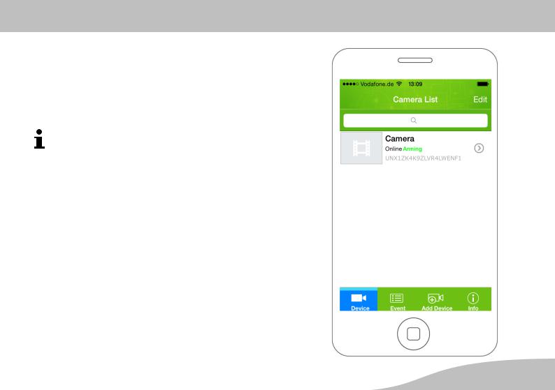
When a camera has been found and integrated success fully in the ProHomeIPC App, the corresponding camera is displayed on the start screen.
In this view, all the cameras integrated in the
ProHomeIPC App are displayed.
We recommend that you assign each camera con nected an unambiguous name (refer to Section
Name).
You are provided with a view of
the unambiguous user identifier (UID) of the camera,
the name (designation) of the camera,
the monitoring status of the camera,
the alarm preset status of the camera and
the possibility of connecting new cameras by means of the ProHomeIPC App.
G |
27 |
Operating the Camera (iOS)
Context Menu of the ProHomeIPC App
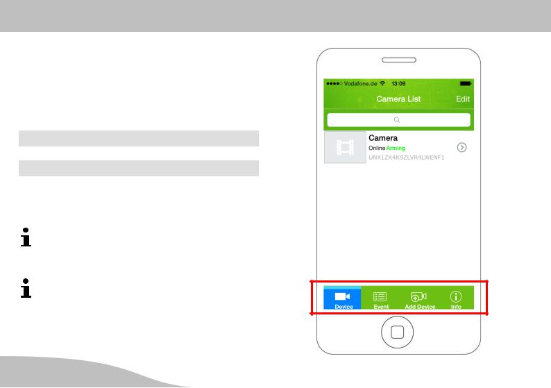
Context Menu of the ProHomeIPC App
At the bottom edge of the start screen are four buttons which can be used to complete different settings and func tions.
1.Touch the respective button to define the setting or start the function.
Device
Event
Add Device
Info
The settings or functions assigned to the individual but tons are described in the following sections.
The following settings can be defined using smart phones and tablets PCs with the Android operating system as well as using smartphones and tablet PCs with the iOS operating system.
The following settings only affect the camera select ed. Information on particular, individual features is provided at the respective point.
28 |
G |
 Loading...