


Grand Rapids, Michigan, U.S.A. 49504-5298
USER’S OPERATING AND INSTRUCTION MANUAL
MODEL 690-NC2
STEAM CONVECTION
OVEN
0690NC2-S20000-CV
INDEX
Section Description
Document No. Page No.
SAFETY INSTRUCTIONS ------------------------------- 0690S20040 --------------------- 1-1
DESCRIPTION/SPECIFICATIONS ------------------- - 0690S20041------------- --------- 2-1
Description -------------------------------------------------------------------------------------- 2-1
Physical Specifications----------------------------------------------------------------------- 2-1
INSTALLATION / SETUP -------------------------------- 0690S20042 --------------------- 3-1
Inspection --------------------------------------------------------------------------------------- 3-1
Location Selection ---------------------------------------------------------------------------- 3-1
Sealing Oven to Mounting Surface ------------------------------------------------------- 3-1
Oven Setup ------------------------------------------------------------------------------------- 3-2
Electrical Connection ------------------------------------------------------------------------- 3-2
Water Connection ----------------------------------------------------------------------------- 3-4
Venting ------------------------------------------------------------------------------------------- 3-5
Test Cycle --------------------------------------------------------------------------------------- 3-5
OPERATING INSTRUCTIONS ------------------------- 0690S20043 --------------------- 4-1
Beginning Operation ------------------------------------------------------------------------- 4-1
The Keyboard and Displays --------------------------------------------------------------- 4-1
Idle Mode --------------------------------------------------------------------------------------- 4-2
Running an Automatic Program ---------------------------------------------------------- 4-2
Running Two Automatic Programs at the Same Time ------------------------------ 4-3
Pre-Alarm -------------------------------------------------------------------------------------- 4-3
Running a Manual Program --------------------------------------------------------------- 4-3
Adjusting the Temperature ----------------------------------------------------------------- 4-4
Adding Steam --------------------------------------------------------------------------------- 4-5
Opening and Closing the Vent ------------------------------------------------------------ 4-5
Changing the Fan Setting ------------------------------------------------------------------ 4-5
PROGRAMMING ------------------------------------------- 0690S20044 --------------------- 5-1
TROUBLESHOOTING ------------------------------------ 0690S20046 --------------------- 6-1
Error Code Display --------------------------------------------------------------------------- 6-1
Solving Other Problems --------------------------------------------------------------------- 6-2
Advanced Functions ------------------------------------------------------------------------- 6-5
Advanced Setup Mode (Re-calibration) ------------------------------------------------- 6-6
MAINTENANCE -------------------------------------------- 0690S20045 --------------------- 7-1
Cleaning ----------------------------------------------------------------------------------------- 7-1
Lubrication -------------------------------------------------------------------------------------- 7-1
Removal and Replacement Guide ------------------------------------------------------- 7-2
RECOMMENDED SPARE PARTS -------------------- 0690S20047 --------------------- 8-1
Continued
0690S20049 0-1
INDEX (Continued)
Section Description
Document No. Page No.
REPLACEMENT PARTS SECTION
ELECTRICAL SUB PANEL ------------------------------ 0690S20050 --------------------- 9-1
Drawing ----------------------------------------------------------------------------------------- 9-1
Parts List --------------------------------------------------------------------------------------- 9-2
FRONT PANEL & OTHER PANELS ------------------ 0690S20051 -------------------- 10-1
Drawing ---------------------------------------------------------------------------------------- 10-1
Parts List -------------------------------------------------------------------------------------- 10-2
DOOR ASSEMBLY ---------------------------------------- 0690S20052 -------------------- 11-1
Drawing ---------------------------------------------------------------------------------------- 11-1
Parts List -------------------------------------------------------------------------------------- 11-2
HOUSING / CHAMBER ASSEMBLY ----------------- 0690S20053 -------------------- 12-1
Drawing ---------------------------------------------------------------------------------------- 12-1
Parts List --------------------------------------------------------------------------------------- 12-2
WATER SYSTEM ASSEMBLY ------------------------- 0690S20054 -------------------- 13-1
Drawing ---------------------------------------------------------------------------------------- 13-1
Parts List -------------------------------------------------------------------------------------- 13-2
DAMPER CONTROL ASSEMBLY --------------------- 0690S20055 ------------------- 14-1
Drawing ---------------------------------------------------------------------------------------- 14-1
Parts List -------------------------------------------------------------------------------------- 14-2
ELECTRICAL DIAGRAMS ------------------------------ 0690S20056 -------------------- 15-1
Wiring Diagram 208 / 240 V -------------------------------------------------------------- 15-1
Wiring Diagram 375 / 480 V -------------------------------------------------------------- 15-2
WARRANTY ------------------------------------------------ GEN 040225
WARRANTY PROCEDURE ---------------------------- GEN 040226
RETURNED PARTS POLICY -------------------------- GEN 040227
REV. 2/26/04
0690S20049 0-2

SAFETY INSTRUCTIONS
WARNING
VARIOUS SAFETY DEVICES AND METHODS OF GUARDING HAVE BEEN
PROVIDED ON THIS OVEN. IT IS ESSENTIAL HOWEVER THAT THE OVEN
OPERATORS AND MAINTENANCE PERSONNEL OBSERVE THE FOLLOWING
SAFETY PRECAUTIONS. IMPROPER INSTALLATION, MAINTENANCE, OR
OPERATION COULD CAUSE SERIOUS INJURY OR DEATH.
1. Read this manual before attempting to operate your oven. Never allow an untrained
person to operate or service this machine.
2. This oven must only be installed by qualified personnel. It also must be installed to
the specifications of local plumbing and electrical codes. See the installation section
of this manual for additional requirements.
3. Connect the oven to a properly grounded electrical supply that matches the
requirements shown on the electrical specification plate and follow specifications of
local electrical codes.
4. Disconnect and lock-out the oven from the power supply before cleaning or
servicing.
5. Check and secure all guards before starting the oven.
6. Observe all caution and warning labels affixed to the oven.
7. Use only proper replacement parts.
8. Wear proper personal protective safety equipment.
9. Keep Hands away form the moving parts of this oven while it is in operation.
10. In addition to these general safety instructions, also follow the more specific safety
instructions given for the different areas of the oven in the operating instructions.
WARNING
DO NOT USE FOR OTHER THAN ORIGINALLY INTENDED PURPOSE.
0690S20040 1-1
DESCRIPTION/SPECIFICATIONS
Description
The Oven is a stainless steel, electric, forced air, (convection), oven with steam injection
capabilities. This oven offers consistent baking at all rack levels due to the careful
positioning of the heating and air circulation systems.
In addition to the above, this oven also offers many other features. It is well insulated
with a high quality asbestos free insulation. It is compact, attractive, quiet, and is
easily maintained. Should electrical servicing ever be required the electrical
components are readily accessible by removing the side or back panels.
The lighted, tempered glass door with its high temperature seal allows a full view of the
trays in the oven during baking.
The oven computer allows you to bake two items at once which makes the oven more
productive. It also has one of the fastest temperature recoveries on the market allowing
the oven to be turned off during non-peak hours, thus saving energy.
The oven has many protective features such as not allowing heating of the elements
when the door is open. Other features are resettable thermal overloads on the motors, a
high-limit thermostat, and a magnetic circuit breaker on the control circuit.
The computer allows easy selection of baking programs. The programs combine
precise control of the pre-heat temperature, baking temperature, time, pre-alarm, steam,
and damper control. This allows precise baking by even inexperienced individuals.
Physical Specifications
Electrical Options Available:
3 phase, 60 hz, 480VAC, 27 Amps.
3 phase, 60 hz, 208VAC, 48 Amps.
3 phase, 60 hz, 240VAC, 53 Amps.
3 phase, 50 hz, 375VAC, 22 Amps
Product Capacities:
The Standard oven will hold (8) 18" X 26" pastry baking trays
these trays will be approximately 3-5/16 inches apart when in
the oven.
6, 12 and 16 tray ovens are also available.
Rev. 8-12-99
0690S20041 2-1
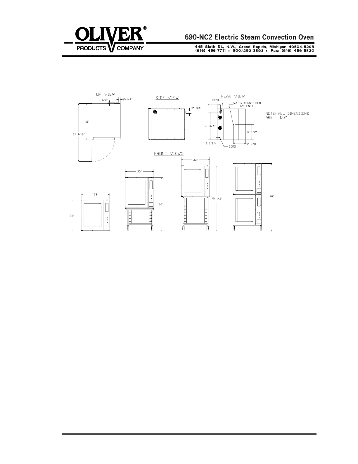
Space Requirements:
Figure 3.0
single: 42” Deep x 33” Wide x 35-3/4” high.
single with short stand and casters: 62” high.
single with tall stand and casters: 75-1/2”
stacked ovens with casters: 78”
Clearance:
Left side = 2”.
Right side = 12” without casters to have access to electrical components,
2” with casters.
Back side = 4” to allow for water connections and venting.
Net Weight: Approximately 500 pounds.
Shipping Weight: Approximately 675 pounds.
Rev. 11-1-01
0690S20041 2-2
INSTALLATION / SETUP
Inspection
Before excepting delivery inspect the carton and machine for damage. Note any
damage found on the shipping documents. Remember shipping damage is not
by your warranty, and is the responsibility of the carrier. Also report the damage to the
dealer from which the oven was purchased for further direction and assistant in filing a
claim with the carrier.
Location Selection
Select a location where the oven will be used. The oven must be set on a flat level
surface. It should have a grounded power supply of the same rating as shown on the
nameplate located on the rear of the oven and this power supply must be capable of
carrying the load that the oven will put on it (See “Electrical Connection” below). The
oven must also be placed near both a water supply and an area where the oven can be
properly vented (See “Water Connection” and “Venting” below).
Ovens with casters should be placed so that they have a minimum of two inches on
each side and a minimum of four inches in the rear of the oven to provide for proper
venting, water, and electrical connections.
Ovens without casters should be placed so that there is a minimum of two inches on all
sides, except for the side with the electrical panel, (right side), which should have a
minimum of twelve inches. The rear of an oven without casters should be a minimum of
four inches away from adjacent surfaces to allow room for the electrical, water and
venting connections.
Sealing Oven to Mounting Surface
covered
CAUTION
MAKE SURE THAT THE MOUNTING SURFACE IS ABLE TO SUPPORT THE
WEIGHT OF THE OVEN WHICH IS APPROXIMATELY 500 POUNDS PLUS AN
ADEQUATE SAFETY FACTOR BEFORE PLACING IT ON THE SURFACE.
The oven must be
For the purpose of sealing the unit a tube of NSF/FDA approved silicone sealant has
been provided with your unit. Apply, to the surface that the oven will rest on, a
continuous bead of sealant approximately 1/2 inch in from each of the four sides of the
oven. After the oven has been placed over this bead apply a second generous
continuous bead at the joint where the oven contacts the mounting surface thus totally
sealing the bottom of the oven to that surface.
0690S20042 3-1
sealed to the mounting surface to comply with local sanitation codes.
Oven Setup
Ovens may be mounted to a fixed surface, attached to an “Oliver” oven rack with casters
or stacked. For associated mounting heights for the above options see figure 3.0 on
page 2-2.
CAUTION
USE CARE WHENEVER MOVING OVENS MOUNTED ON RACKS AS THEY ARE
TOP HEAVY AND PRESENT A TIPPING HAZARD.
Ovens attached to “Oliver” oven racks must be
Stacked ovens should be setup as shown on page 2-2 being sure that the alignment
pins on the top of the lower oven are securely positioned into the holes in the base of the
upper oven.
After the Oven has been mounted to a surface, attached to a rack, or stacked, remove
the shipping bracket, which secures the door. To remove the shipping bracket, remove
the two screws from the top of the door with a screwdriver and open the door. Replace
these screws and tighten securely. To remove the shipping bracket from the front of the
oven liner, remove the two hex head screws with a wrench. The bracket and screws
may be discarded. Replace the removed hex head screws with the two screws provided
in a bag taped to the floor of the oven chamber and tighten securely.
Electrical Connection
securely fixed to the rack with bolts.
WARNING
THE OVEN MUST BE CONNECTED TO A PROPERLY GROUNDED ELECTRICAL
SOURCE OF THE SAME RATING AS THE MACHINE. FAILURE COULD RESULT IN
AN ELECTRICAL SHOCK WHICH MAY CAUSE INJURY OR DEATH.
WARNING
ALL WIRING AND ELECTRICAL REPAIRS SHOULD BE DONE BY A QUALIFIED
ELECTRICIAN. FAILURE TO DO SO MAY CAUSE SERIOUS INJURY OR DEATH.
CAUTION
SPECIAL HEAVY DUTY ELECTRICAL SERVICES AND WALL DISCONNECTS
MUST BE PROVIDED FOR SAFE OPERATION OF THE OVEN.
The following service requirements are recommended, dependent on the voltage of the
unit you have purchased. Your oven’s requirements can be found on the nameplate
attached to its rear surface.
0690S20042 3-2
Electrical Connection (continued)
For voltages other than those shown below please contact the factory. Check the
voltage at the disconnect before proceeding to the next step.
480 Volts = 30 Amp service
375 Volts = 30 Amp service
240 Volts = 60 Amp service
208 Volts = 60 Amp service
The oven is shipped from the factory with a power cord, which does not include a plug.
The power cord should be wired to a disconnect enclosure which is accessible from the
oven work area, leave at least two feet of slack so that access can be gained to the
ovens back and right side. A plug may be used between the disconnect enclosure and
the oven instead of hard wiring as described above. This makes sliding the oven out for
service more convenient. Whatever method is used the oven should be wired in a
manner which would conform to the U.S. “National Electric Code”.
CAUTION
FANS MUST ROTATE IN THE CLOCKWISE DIRECTION FOR PROPER AIRFLOW.
IMPROPER DIRECTION MAY CAUSE UNEVEN BAKES AND LONGER BAKING TIMES.
Check fan rotation for clockwise direction. After the oven has been “Set Up” and
connected to the electrical service do the following to check the rotation of the fans. At
the lower right hand corner of the front surface of the oven you will find a small
rectangular panel held in place with two thumb screws. Removing these screws and the
panel they secure will expose the “Manual” controls of the oven. Use the following
sequence to start the oven to check fan rotation direction:
• Switch the oven to manual mode.
• Turn the main power switch on, (green button above
oven should start and fan rotation can now be checked.
• Once complete, turn the main power switch off, (red button above
controls), return the oven to automatic mode and replace the cover.
If the rotation is incorrect remove and interchange any two of the three incoming power
leads (red, white and black), at the plug or disconnect enclosure and retest.
the manual controls). The
the manual
0690S20042 3-3
Water Connection
All water connections must comply with the basic plumbing code of the Building Officials
and Code Service Sanitation Manual of the Food and Drug Administration (FDA)
CAUTION
WATER PRESSURES GREATER THEN RECOMMENDED CAN CAUSE EXCESS
WATER TO ENTER THE OVEN CAUSING WATER TO LEAK AT THE DOOR AND
ALSO CAUSE THE TEMPERATURE TO DROP SEVERELY AFFECTING THE BAKE.
USE A PRESSURE REGULATOR TO REGULATE THE PRESSURE.
The oven must be connected to a water supply to enable the oven to produce steam for
baking. As shipped from the factory the oven will have a solenoid valve at the back
center of the oven, (See figure 3.0 page 2-2). This valve has an internal 1/4” NPT thread
for connection. Water pressure should be a maximum of 60 to 70 PSI and the water
must clean. Use a pressure regulator and a water strainer/filter to meet these
guidelines. Before making the water connection flush all lines and install the regulator
and filter. Remember solenoid failure and related problems caused by dirt may not be
covered by your warranty.
NOTE
HARD WATER LEAVES MINERAL DEPOSITS ON GLASS AND OTHER SURFACES
WHICH DETRACT FROM OVEN APPEARANCE.
The solenoid valve can be checked after “Set Up” and the “Electrical and Water
Connection” has been completed. At the lower right hand corner of the front surface of
the oven you will find a small rectangular panel held in place with two thumb screws.
Removing these screws and the panel they secure will expose the “Manual” controls of
the oven. Use the following sequence to start the oven to check solenoid operation.
• Switch the oven to manual mode.
• Turn the main power switch on, (green button above
• Press the steam button briefly and release, water should spray from each of the
spray nozzles. Adjust the spray nozzles if required so that they are vertical and
spray directly into the fans.
• Once complete, turn the main power switch off, (red button above
controls), return the oven to automatic mode and replace the cover.
the manual controls).
the manual
0690S20042 3-4
Venting
On the rear side of the oven near the top is a 3” diameter exhaust vent protruding
approximately 3/4” from the oven. Vent the exhaust (hot air and steam) to the outside by
connecting to this vent.
WARNING
HOT STEAM CAN CAUSE SEVERE BURNS AND DAMAGE TO THE SENSITIVE
ELECTRONICS. VENT STEAM TO OUTSIDE TO AVOID INJURIES AND DAMAGE.
Test Cycle (done manually without computer)
After completing the Set Up, Electrical and Water connections, and Venting, you may
wish to run the oven through a test cycle to verify that everything is ready. At the lower
right hand corner of the front surface of the oven you will find a small rectangular panel
held in place with two thumb screws. Removing these screws and the panel they secure
will expose the “Manual” controls of the oven. Use the following sequence to run the
oven through a test cycle.
• Switch the oven to manual mode.
• Set the Temperature Control to a desired temperature such as 400 degrees.
• Turn the main power switch on, (green button above
• Once the oven reaches the set temperature press the steam button briefly and
release, (a second or two), water should spray from each of the spray nozzles
directly into the fans which will spread the water onto the heating elements
causing steam. Under normal conditions SOME STEAM WILL ESCAPE
THROUGH THE FRONT DOOR GASKET.
• Once complete, turn the main power switch off, (red button above
controls), return the oven to automatic mode and replace the cover.
the manual controls).
the manual
0690S20042 3-5
CANC
OPERATING INSTRUCTIONS
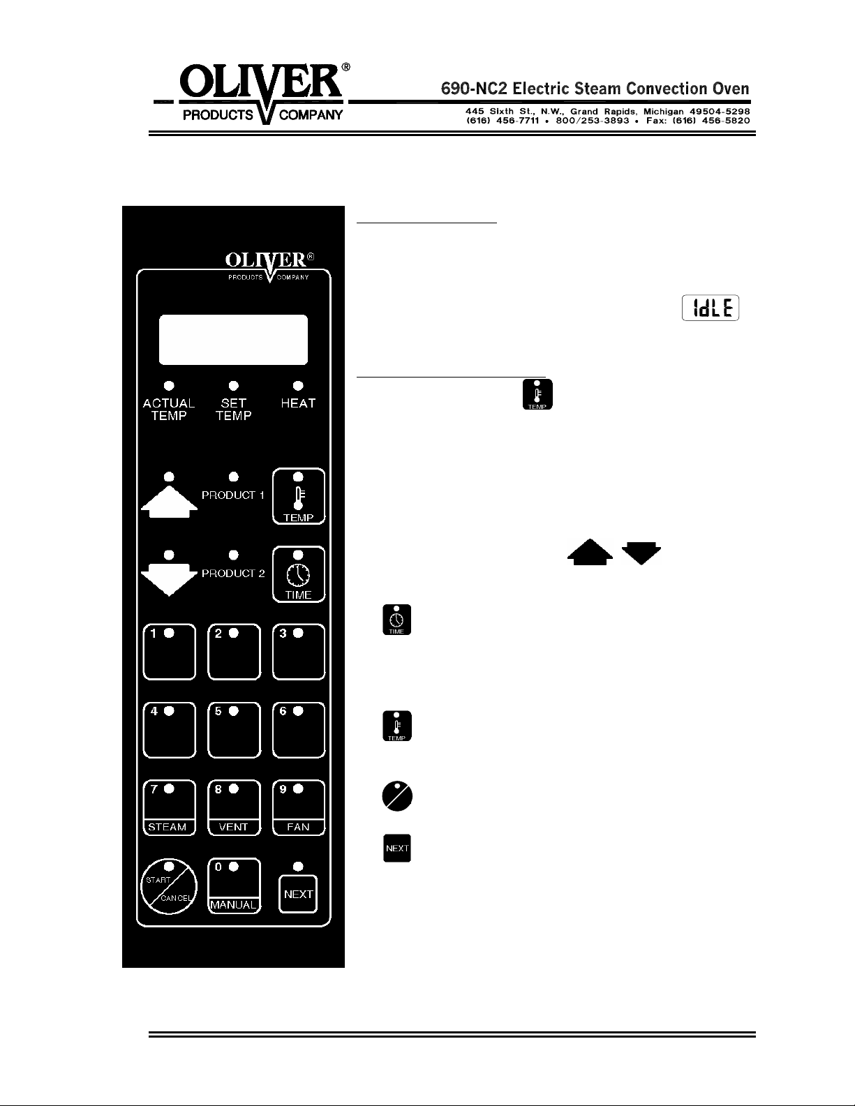
Beginning Operation
First turn the oven on by pressing the black ‘Start/ Reset’
button below the keyboard and display. The computer will
then check the oven and itself for any faults. Then the
display will show the current mode which is idle
the preset initial temperature is 250 °F.
The Keyboard and Displays
• Press the temp. key
to toggle the display
between Time, Actual Temp., Set Temp, and Idle.
The display LED’s will light for actual and set
temperature.
• The Heat LED will light when the heating elements are
on.
• Use the up and down keys
to add and
subtract time in whole minute increments.
•
The time key is used when a bake is running.
Press this key to display the time remaining. During 2
product baking pressing this key will briefly display the
product with the most time remaining.
•
The temp key will change the display between
set point, set temp, and time remaining.
START
EL
•
The Start/Cancel key is pressed to start and
cancel various operations.
•
The next key is used in programming.
• Other detailed key descriptions are explained in the
next sections.
0690S20043 4-1

CANCELS
Idle Mode
From Idle mode you can:
• Run an automatic program.
• Run a manual program.
• Adjust the temperature.
• add steam.
• open and close the vent.
• change the fan setting.
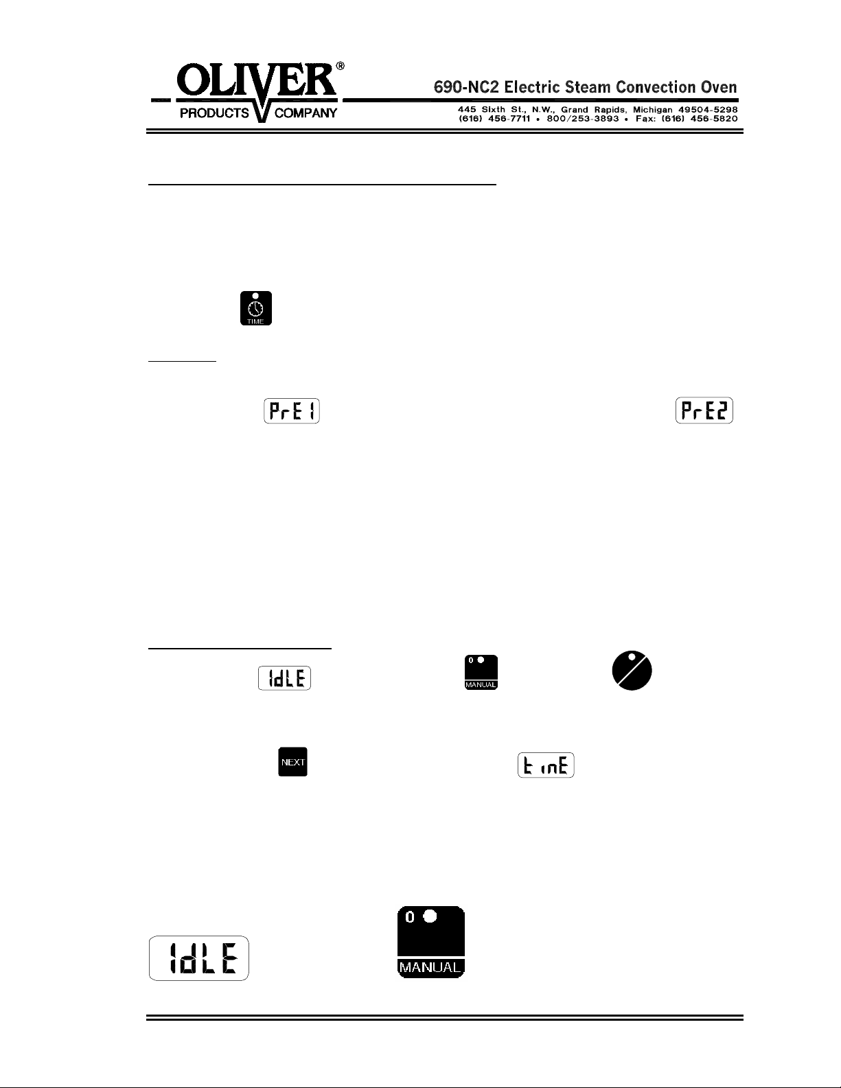
Running an Automatic Program
1. From Idle mode
enter the program number (01 - 40) using the keypad
2. Wait 3 seconds or press the start key to begin preheat stage.
3. Wait for oven to reach set temperature. The display will show lo or hi and the menu
number. When the set point is reached the buzzer will sound and the display will
show ready
.
4. Put product into the oven.
5. Close door, bake begins.
START
6. Pre-Alarm #1
will sound if programmed, press
CANCEL
to cancel the alarm.
For more details see the Pre-Alarm section.
7. Alarm will sound when bake is finished and display will show
program number
.
. and the
Open the door to end the program, this will hold the current bake temperature, add time
if required by pressing the up button. OR
TART
Press cancel
to end the bake and return the holding temperature to 250 °F.
0690S20043 4-2
Running two Automatic Programs at the Same Time
If two programs are compatible they may be run at the same time. They must both be
single stage menus with identical temperatures. While the program is running (Product
1 LED will be lit) enter the second program number (01-40) and hit start. Now both
product LED’s will be lit, the one with the shortest time will have a flashing LED and the
time remaining will be displayed. To briefly display the time of the other product press
the Time key
.
Pre-Alarm
The pre-alarm will go off during the bake as programmed. The alarm will sound and the
display will show
(the 1 is for product-1, product-2 pre-alarm displays )
press cancel or open the door to clear the alarm.
For advanced users: While the pre-alarm is displayed it is possible to add time to it. Do
this by pressing the up key. Press the up key once for each minute. Then wait three
seconds or press the start key. Example: by adding 2 minutes to the pre-alarm, another
pre-alarm will sound in two minutes. It is then possible to add time again and again.
If the alarm is cleared by opening the door it is still possible to add time. However if the
door is then shut and the up key isn’t pressed within three seconds, the pre-alarm will be
cleared and it will not be possible to add time.
Running a manual program
START
From idle mode
press the manual key then press start
CANCEL
.
Now enter the desired temperature by using the numeric keypad or the arrow keys to
scroll.
Press the next key
to advance. Display will show which prompts you to
enter the time.
Using the numeric keypad enter the time in minutes and seconds.
Example: Run a manual program at 350 °F for 10 minutes
Display Shows Press Button(s)...
0690S20043 4-3
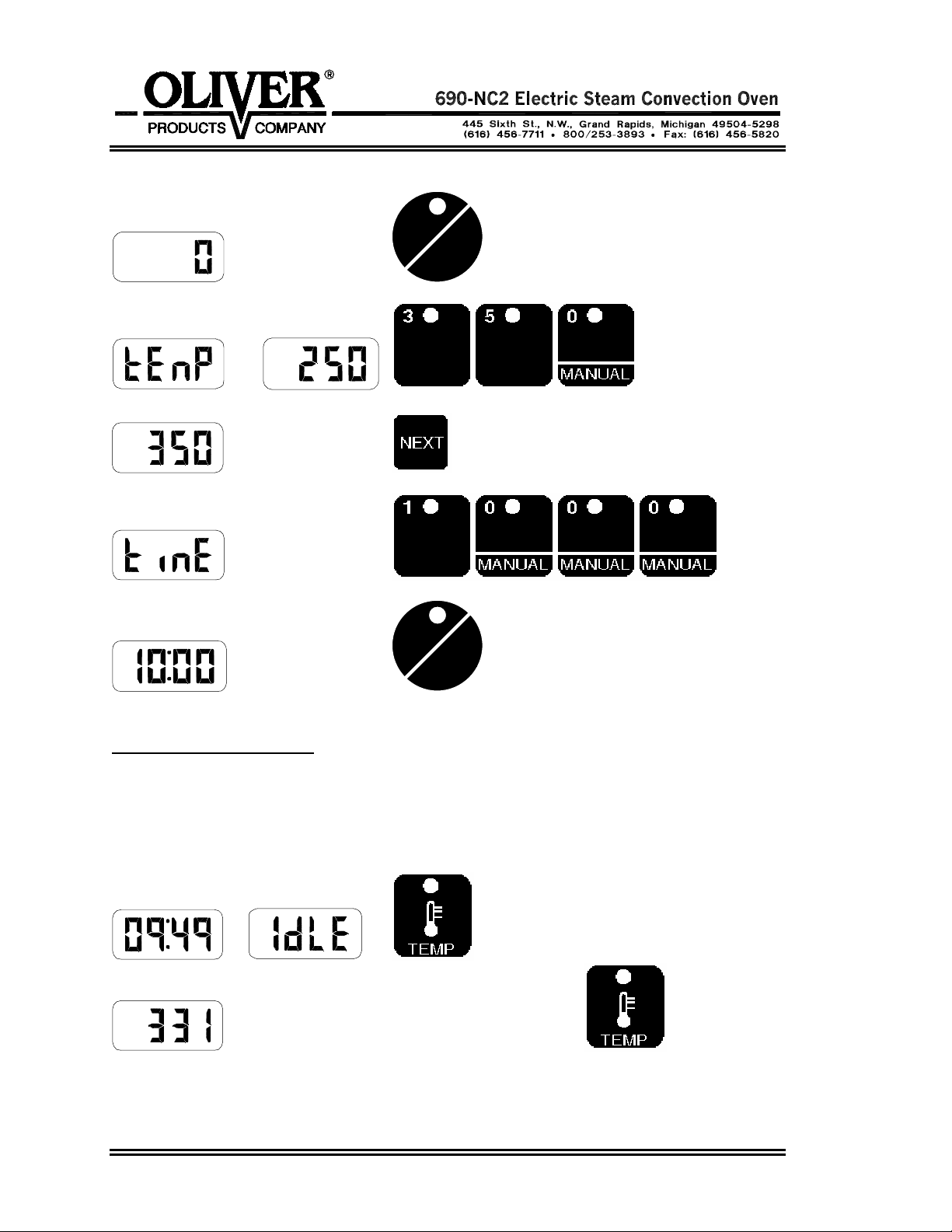
START
CANCEL
and
START
CANCEL
Countdown begins.
Adjusting the Temperature
The temperature can be changed while in manual or idle mode. Here is an example of
how to change the temperature from 350 to 380.
Display Shows Press Button(s)...
or
Actual temp, Press the temp key again
0690S20043 4-4

Set temp. Use and to scroll to 380.
Press to go back to ‘Time or Idle’.
Adding Steam
It is possible to inject steam at any time the door is closed by pressing and holding the
7/steam button
Opening and Closing the Vent
It is possible to toggle the vent open and closed by pressing the 8/vent key
will not work when a program is running. Use this feature to vent some of the steam out
of the oven before opening the door. However, some hot steam will always remain.
.
. This
CAUTION
SUPER HEATED STEAM IS INVISIBLE AND IS POSSIBLY PRESENT IN THE OVEN.
THIS STEAM MAY BURN SKIN. STAND AS FAR AS POSSIBLE AWAY FROM
OVEN WHEN OPENING THE DOOR. THEN PROCEED WITH CAUTION.
Changing the Fan Setting
The fan cannot be changed when a program is running.
In manual mode the fans can be set to high
or low by pressing the
9/fan key
In Idle mode the fans can be set to high
using the 9/fan key
Cool down allows the oven chamber to quickly cool down by keeping the blowers
running while the door is open.
The low fan setting is helpful for high sugar product.
0690S20043 4-5
.
, low , or cool down
.

PROGRAMMING
The following are instructions for editing and creating a menu program.
1. Enter the Program Mode by pressing the up and down keys
simultaneously for 5 seconds.
2. Display shows
for MENU.
3. Key in the menu number you want to program (01-40), or use the up and down keys
to scroll.
Programs 01-20 can hold two stages.
Programs 21-40 hold one stage
4. Press the ‘next’ key
to edit/program the first parameter of the menu.
5. Display will show
enter the preheat temperature. Press the next key
for Pre-Heat. Use the up and down keys or the keypad to
to advance.
6. Display will show
keys
key
to adjust temperature Compensation to on or off. Press the next
to advance.
for Temperature Compensation. Use the up and down
7. Display will show for steam. Use the up and down keys to adjust the steam
time between 0-30, C2, C3, and C4. C2 produces two cycles of 15 second steam.
C3 produces three cycles etc. Press ‘next’ key to advance.
8. Display will show
for stage 1 time. Use up and down keys or keypad to
enter the time in minutes and seconds. Press ‘next’ key to advance.
Example: Enter 1200 for twelve minutes and zero seconds.
9. Display will show
for stage 1 Temperature. Use up and down keys or
keypad to enter the Temperature between 250°F and 500°F. Press the ‘next’ key to
advance.
10. Display will show
for stage 1 fan. Use up and down keys to scroll between
Hi and Lo fans. Press ‘next’ key to advance.
0690S20044 5-1

11. Display will show
for stage 2 time. Stage 2 only works for menus 01-20
(For menus 21-40 skip to the Pre-alarm). Use up and down keys or keypad to enter
the time in whole minutes. Entering 0 will eliminate stage 2 and skip you past the
rest of the stage 2 parameters. Press ‘next’ key to advance.
12. Display will show
for stage 2 Temperature. Use up and down keys or
keypad to enter the Temperature. Press the ‘next’ key to advance.
13. Display will show
for stage 2 fan. Use up and down keys to scroll between
Hi and Lo fans. Press ‘next’ key to advance. Best results are achieved with the fans
on HI.
14. Display will show
for Pre-Alarm. Use the up and down keys to select the
Pre-Alarm in whole minutes (0 to 30). Example: A pre alarm value of 1 will sound an
alarm 1 minute before the time expires. Press ‘next’ key to advance.
15. Display will show
for Vent. Use the up and down keys to scroll closed,
open or 1-14 minutes. Venting example: A vent time of one minute will make the
vent open one minute before the end of the menu program. Press ‘next’ key to
complete program and return to the menu prompt.
16. Enter the next menu number to be programmed or press cancel to leave
programming mode.
0690S20044 5-2

p
g
g
TROUBLESHOOTING
WARNING
TROUBLE SHOOTING OF ELECTRICAL EQUIPMENT SHOULD BE PERFORMED
BY QUALIFIED PERSONNEL ONLY. ELECTRICAL POTENTIAL IS GREAT
ENOUGH TO CAUSE INJURY OR DEATH.
Error Code Display
The error code is visible in the display. The list below outlines the standard error codes
associated with this unit. They are designed to isolate specific problem areas and aid in
troubleshooting your control.
Problem Probable Cause Solution
Er01-
(ROM) Checksum error
Er02-
(RAM) Checksum error
Er05-
Eprom Error data. or Replace Eprom
Er06-
Zone 1/Top probe A/D
underflow error outside the sensor range.
Er07-
Zone 1/Top probe
overflow error
Er08-
Zone 2/Bottom probe A/D
underflow error outside the sensor range.
Er09-
Zone 2/Bottom probe
overflow error
Er10-
Stack overflow error
Er11-
Zone 1/Top probe error
Er12-
Zone 1/Top probe shorted Should be greater than
Internal ROM is defective Turn Off and then Restart.
Internal RAM is defective Turn Off and then Restart.
Power loss while storing
E
rom has been
Turn Off and then Restart.
changed.
Incorrect sensor type.
Measurin
temperature
Check sensor.
Open sensor Check for an open sensor.
Incorrect sensor type.
Measurin
temperature
Check sensor.
Open sensor Check for an open sensor.
Microprocessor error Turn Off and then Restart.
Open RTD probe Check for an open probe
Probe is out of range Check probe for short.
90 ohms.
0690S20046 6-1

p
g
p
g
Continued
Error Code Display (continued):
Problem Probable Cause Solution
Er13- Open sensor Check for an open probe.
Zone 2/Bottom probe
open sensor
Er14- Probe is out of range. Check probe for short.
Zone 2/Bottom probe Should be greater than
shorted sensor 90 ohms.
Er15-
Zone 1 loop error
Er16-
Zone 2 loop error
Faulty heater
Shorted sensor
Bad heater contactor
Faulty heater
Shorted sensor
Bad heater contactor
Check heater elements
Check sensor
Check switchin
Check heater elements
Check sensor
Check switchin
robe
device
robe
device
CAUTION
BEFORE WORKING ON A OVEN WHICH HAS BEEN RECENTLY USED
ALLOW SUFFICIENT TIME FOR IT TO COOL TO PREVENT BURNS.
SOLVING OTHER PROBLEMS
No Power.
• The machine is not plugged in.
• There is no power available at the outlet/disconnect
• The circuit breaker has tripped. Reset by pressing the switch so that it is flush with
the front panel. (Control panel only)
• A fuse has blown.
• The transformer has failed. (Control panel only)
No Heat or Oven Heats Slowly
A cooled dry empty oven can be heated from room temperature to 300 °F in four to six
minutes. If the oven is not meeting this specification, check the following.
• Check the fuses
• Check the two contactors.
Continued
0690S20046 6-2

No Heat or Oven Heats Slowly (Continued)
• Check heater bank continuity.
• The fault/high limit lamp is on, see the trouble shooting suggestions for this area
below.
The Fault/High Limit Lamp Is On
• Motor has overheated. (The blower motors are equipped with an internal thermal
switch). Turn the oven off and try to restart after the motor has cooled.
Possible causes:
1.) The motor bearing or winding has failed.
2.) Something is binding the motors or blower fans.
3.) The rear of the oven lacks sufficient clearance to allow proper air circulation.
• Oven temperature is too high. (Your oven comes with a high temperature limit
switch set at approx. 575 °F. This switch will reset when the oven has cooled.)
• A power interruption has occurred
No Steam
• The water line to the oven may not have been turned on or someone has turned it
off.
• Your water line filter may be plugged or need servicing.
• The water solenoid valve may be dirty and stuck shut.
• The water solenoid valve may have failed.
• The water pressure may be to low, the oven requires between 60-70 psi.
• The water spray nozzles inside the oven chamber which spray water into each of the
blower fans may be plugged, remove the nozzle assembly and clean.
• The nozzle assembly, which sprays water into the blower fans, is not vertical and is
not spraying the water directly into the fans as it should.
The Steam Will Not Stop /or Continuos Steam
It is normal for water to drip from the spray nozzles for several seconds after steaming,
however if it continues to drip or run, check the following.
• The water solenoid valve may be dirty and stuck open.
• The water solenoid valve may have failed.
0690S20046 6-3

Steam Is Leaking From the Door
It is normal for some steam to escape from the door during the steaming operation,
however, if excessive amounts escape you should check the following.
• The door seal may be damaged.
• The door may not be latching properly.
The Door Will Not Close
• Slamming the door too hard can cause it to bounce off of the seals, not allowing the
door time enough to latch properly.
• Sometimes after replacement of the door seals the strike may need to be reshimmed to generate the proper seal. Remember only a single shim should be
used, order shim kit number 690-0148K when replacing seals.
• Check for a worn or broken latch or strike.
• The Latch mounted to the door may be too far away from the strike. It may be
adjusted left to right.
One or both of The Blower Fans Will Not Run
• The oven liner may be rubbing on the fan preventing its rotation.
• A motor fuse may need to be replaced.
• The door switch may not be working.
• The fault/high limit lamp is on, see the trouble shooting suggestions for this area
above.
• The high limit switch has failed.
• A blower fan motor may have failed.
The Blower Fans Run Continuously
Other than when the oven is in “Cool Down” mode the blower fans should not run when
the door is open. Things which may make this happen are:
• A failure of the door switch.
• A blower fan motor contactor failure.
0690S20046 6-4

The Oven Is Overheating
This may be a normal condition experienced when the oven is empty. Normally the
oven’s program will attempt to correct temperature based on a full oven’s reqirements.
• A heat contactor may have failed.
• There is an error in your program, if it is a new program check that the temperature
was entered correctly.
• The oven may be out of calibration. See the Advanced setup Mode on page 6-6 to
find out how to re-calibrate the oven.
The Oven is Baking Unevenly
• A blower fan or fans are turning in the wrong direction.
• The oven may be out of calibration. See the Advanced setup Mode on page 6-6 to
find out how to re-calibrate the oven.
• The vent damper may be stuck open.
• One or more of the blower fans may not be turning. See page 6-4 possible causes
for this
• You may have low voltage at the power source.
Advanced Functions
Checking the software version and temperatures.
Press
Advance through the parameters by using the
key. The parameters are as follows.
Customer number should be 48.
Software Revision should be 5 or higher.
Zone 1 temperature shows the temperature reading of the top probe
without offset.
Continued
0690S20046 6-5

Advanced Functions (Continued)
Zone 2 temperature shows the temperature reading of the top probe
without offset.
Advanced Setup Mode (Re-calibration)
To change offset temperature or run on only 1 probe enter the following key sequence.
Advance through all parameters by using the
key. Do not change any of the
parameters except the ones listed below. This is only required after a probe fails. The
parameters are as follows.
Default is 2, 1 can be used when only the top probe is working.
and adjust with the up and down key for temperature offset for probe 1
and 2.
0690S20046 6-6

MAINTENANCE
WARNING
NEVER ATTEMPT TO CLEAN OR SERVICE THIS OVEN UNTIL IT HAS BEEN
DISCONNECTED FROM THE POWER SUPPLY AND IS COOL TO THE TOUCH.
NOTE
REMEMBER A CLEAN OVEN WILL LAST LONGER AND WORK BETTER.
Cleaning
The outside of the oven should be cleaned daily by wiping it with a clean damp cloth or
by using any suitable stainless steel cleaner. A solution made up of a mild detergent
with water will normally be sufficient for routine cleaning of the interior of the oven.
When finished dry the surfaces with a clean cloth.
The glass door should be cleaned daily using normal glass cleaners.
For more difficult cleaning jobs such as where there are burned on or greasy deposits, or
heat tint, you should use an abrasive pad. Remember for best results always keep the
stainless steel shiny.
To simplify major cleanings the inner liner may be removed by first removing the nozzle
assembly in the back of the oven with an open end wrench, and then by removing the
eight slotted head screws which secure the liner. Six of these screws are in the front of
the oven while two additional screws are on the rear panel adjacent to the nozzle
assembly.
Clean the rear fan cover frequently to insure air circulation through the electrical
compartment. This will lessen the possibility of heat related electrical problems.
The heating elements themselves normally do not require cleaning.
Lubrication
Occasionally put a few drops of oil on the pivot points of the door. No other items
requires lubrication.
CAUTION
NEVER LUBRICATE THE MOTORS
0690S20045 7-1

Removal and Replacement Guide
Removing the Inner Liner:
• First remove the nozzle assembly in the back of the oven.
• Remove the eight slotted head screws which secure the liner. Six of these screws
are in the front of the oven while two additional screws are on the rear panel adjacent
to the nozzle assembly.
• The liner can now be removed from the oven.
Replacing the Fan or Fan Motor:
WARNING
NEVER ATTEMPT TO CLEAN OR SERVICE THIS OVEN UNTIL IT HAS BEEN
DISCONNECTED FROM THE POWER SUPPLY AND IS COOL TO THE TOUCH.
• First remove the inner liner as described above.
• Next, use a wrench to remove the hex head bolt in the end of the motor shaft which
secures the fan.
• Loosen the two set screws in the hub of the fan.
• Always use a puller to remove the fan from the motor shaft to protect the bearings in
the motor.
• Disconnect wires from motor, wiring connections are in the wiring box on the motor.
• Take off the four nuts and remove the motor.
• Re-install the fans and/or motors by reversing the disassembly procedures.
Changing a Bank of Heating Elements.
• Remove the inner liner as described above.
• Remove the fan(s) as described above.
• Remove the electrical rear side panel by removing the 9 slotted head screws which
secure the cover.
• Remove the wires from the ends of the affected bank of heating elements. Make
sure they are marked so that they can be returned to the new bank of elements
easily.
0690S20045 7-2

Changing a Bank of Heating Elements (Continued).
• Remove the four hex head screws which secure the bank to the housing and remove
the bank of elements.
• The interior surface where the bank of elements were previously attached should be
cleaned completely of any remaining sealant.
• A new bank of elements must be sealed to the housing using a NSF/FDA approved
silicone sealant.
• Finish installing the new elements by reversing the above disassembly procedures.
Replacing the Exterior Door Gasket
• Remove the 18 screws which hold the gasket retainers on.
• Remove the gasket.
• The sheet metal surface of the door where the gasket was attached and the retainers
should be cleaned completely of any remaining sealant.
• Replace the gasket retainers but leave the screws loose.
• Start replacing the gasket on the hinge side of the door beginning about 1-1/2” above
the spot where the two retainers meet. Slide the gasket between the retainer and
the door surface making sure it is seated completely especially in the corners.
• Tighten the gasket retainer screws as you go.
• Completely seal the inside and outside edges of the gasket using a NSF/FDA
approved silicone sealant. (Run a bead underneath the outside edge of the gasket
as well as along the edge
• Allow sealant to dry before closing the door or operating the oven, (approximately
four to five hours).
Replacing the Interior Door Gasket
• Remove the 14 screws securing the door panel (It has the exterior gasket fastened
to it).
• Lay the panel down and remove the gasket from the glass and metal frame.
Rev. 4-28-2000
0690S20045 7-3

Replacing the Interior Door Gasket (Continued)
• Replace gasket and use a NSF/FDA approve sealant between the metal and gasket.
and gasket end to end.
• Set down door frame, rounded gasket side up and run a bead of NSF/FDA approved
sealant around top edge of entire gasket.
• Place glass on top of gasket. This will seal the gasket to the glass.
• Allow sealant to dry, (approximately four to five hours).
• Replace door panel, clamp the front and back door panels together before tightening
the screws.
Changing an Electrical Component
WARNING
NEVER ATTEMPT TO SERVICE THIS OVEN UNTIL IT HAS BEEN DISCONNECTED
FROM THE POWER SUPPLY. ALL ELECTRICAL WORK MUST BE DONE BY A
QUALIFIED ELECTRICIAN.
• Remove the front side panel which is located on the control side.
• After identifying the component which needs to be replaced remove its wires after
marking them for ease of replacement.
• Remove the component.
• Re-install the component by reversing the removal procedures.
Rev. 4-28-2000
0690S20045 7-4

RECOMMENDED SPARE PARTS
PART NUMBER
PART DESCRIPTION NO. REQ’D
5725-9626 Fuse-FRN 8 (208/240V) 2
5725-9442 Fuse-FNQR 4 (375/480V) 2
5725-9634 Fuse-FRN 30 (208/240V 6
5725-9066 Fuse-KTKR-15 (375/480V) 6
5748-6718 Valve-Solenoid 2-Way 1
5760-3194 Transformer (240/480V) 1
5760-3195 Transformer (208/375V) 1
5749-8021 Relay-Power 3-Pole, 25A 3
5708-6808 Block-Contact 1NC 1
5708-6809 Block-Contact 1NO 1
5708-7806 Pushbutton-Green (On) 1
5708-7805 Pushbutton-Red (Off) 1
5757-8819 Switch-Magnetic Proximity Door 1
5757-4125 Breaker-Circuit 2.5A 1
5737-2010 Lamp-Fluorescent 1
5911-9030 Latch-Body 1
0690-0149 Strike-Door 1
6542-0003 Glass-Door 1
6904-6062 Gasket-Door Interior and Exterior 17 ft
5757-8083 Switch-Limit 2
6310-0003 Motor-Gear 1/110 h.p. (For Vent) 1
For Service Parts Call Oliver Products @ 800-253-3893 (continued)
Rev. 2-27-02
0690S20047 8-1

RECOMMENDED SPARE PARTS (continued)
PART NUMBER
PART DESCRIPTION NO. REQ’D
0690-0004 Motor-Blower (208/240/480V) 2
0690-0004-2 Motor-Blower (375V only) 2
0690-0045 Wheel-Blower 2
5712-0655 Sensor-RTD 100 Ohm 2
5712-0029 Coupling-RTD Sensor 2
5704-5011 Cable-Computer/Interface 9 Pin Mate-n-Lock 1
5704-5012 Cable-Computer/Interface12 Pin Mate-n-Lock 1
5712-3261 Interface-Watlow Compatible 1
5712-3267 Computer-Oliver/Watlow 1
5730-2655 Heater-10KW 2
5757-9710 Switch-Thermal Surface Mount (Hi Limit) 1
6310-5027 Fan-Axial 3000 RPM (Cooling Fan) 2
For Service Parts Call Oliver Products @ 800-253-3893
Rev. 10-22-2003
0690S20047 8-2

ELECTRICAL SUB PANEL
0690S20050 9-1

ELECTRICAL SUB PANEL PARTS LIST
ITEM NO PART DESCRIPTION PART NUMBER
007 KIT-CAPACITOR MTG. 5704-6530
018 FUSE-FNQR 4 (375/480V) 5725-9442
FUSE-FRN 8 (208/240V) 5725-9626
019 FUSE-KTKR 15 (375/480V) 5725-9066
FUSE-FRN 30 (208/240V) 5725-9634
021 BLOCK-FUSE CLASS CC (375/480V) 5726-1006
BLOCK-FUSE CLASS CC (208/240V) 5726-1080
031 CAPACITOR 5704-6199
042 INTERFACE-WATLOW COMPATIBLE 5712-3261
043 TRANSFORMER-MULTI-TAPS (all models) 5760-3196
TRANSFORMER-208/380V OVENS ONLY 5760-3195
TRANSFORMER-240/480V OVENS ONLY 5760-3194
044 RELAY-POWER 3 POLE 25A 5749-8021
045 SPACER-NYLON 1/2” 5767-5705
046 SUBPANEL-ELECTRICAL 0690-0039-2
047 BLOCK-TERMINAL 0-14 GA 5770-7463
048 BALLAST-DOOR LAMP 5702-2000
FOR SERVICE PARTS CALL OLIVER PRODUCTS @ 800-253-3893
0690S20050 9-2

FRONT PANEL
Revised 6-1-04
0690S20051 10-1

FRONT PANEL PARTS LIST
ITEM NO PART DESCRIPTION PART NUMBER
349 STRIKE-LATCH 0690-0149
701 PANEL-FRONT CONTROL 0690-0034-2
702 BRACKET-PROX. SWITCH 0690-0042
703 SWITCH-2 POSITION MAINTAINED KNOB 5708-6522
704 BLOCK-CONTACT 1NC 5708-6808
705 BLOCK-CONTACT 1NO 5708-6809
706 PUSHBUTTON-GREEN 5708-7806
707 PUSHBUTTON-RED 5708-7805
708 LIGHT-PILOT 1/2” SNAP-IN RED 5709-0017
709 LIGHT-PILOT 1/2” SNAP-IN GREEN 5709-0019
710 CONTROL-TEMPERATURE 5712-0015
711 COMPUTER-16 KEY 5712-3267
712 KNOB 5736-4005
713 BREAKER-CIRCUIT 2.5A MAGNETIC 5757-4125
714 SWITCH-MAGNETIC PROXIMITY DOOR 5757-8819
717 PUSHBUTTON-”STEAM” 5708-7801
718 BUZZER 5700-6051
719 STRIP-INSULATOR 0690-0155
NOTE
THE REMAINING PANELS AND COVERS ARE SHOWN ON THE LIST BELOW
BUT ARE NOT
ITEM NO PART DESCRIPTION PART NUMBER
050 PANEL-REAR FAN (375/460V) 0690-0038-101
PANEL-REAR FAN (208/240V) 0690-0038-102
101 COVER-TOP 0690-0001-002
102 COVER-HINGE SIDE 0690-0002
105 COVER-ASS’Y-RECESS POCKET 0690-0074K
108 COVER-ELECTRICAL SIDE REAR 0690-0003-201
109 PANEL-REAR RIGHT 0690-0018-2
110 PANEL-REAR CENTER 0690-0018-3
111 COVER-ELECTRICAL SIDE FRONT 0690-0003-202
112 DOOR-FUSE 0690-0141
FOR SERVICE PARTS CALL OLIVER PRODUCTS @ 800-253-3893
Revised 6-1-04
SHOWN ON ANY OF THE DRAWINGS IN THIS MANUAL.
0690S20051 10-2

DOOR ASSEMBLY
Rev. 4-28-2000
0690S20052 11-1

DOOR ASSEMBLY PARTS LIST
ITEM NO PART DESCRIPTION PART NUMBER
301 HOUSING-EMPTY 0690-0021
304 TUBE-SPACER 0690-0024
307 BRACKET-TOP DOOR HOLD 0690-0027
308 BRACKET-BOTTOM DOOR HOLD 0690-0028-1
309 SPACER-DOOR 0690-0030
310 COVER-WIRE 0690-0031
318 GLASS-DOOR 6542-0003
321 FRAME GASKET 0690-0152
324 GASKET-GLASS & DOOR 6904-6012
329 LATCH-BODY 5911-9030
330 DOOR-OUTSIDE 0690-0087-2
331 DOOR-OUTER BACK 0690-0088-3
332 DOOR-INSIDE ASSEMBLY 0690-0089-2
333 NUTBAR 0690-0110-2
334 LAMP-FLUORESCENT 36 WATT 5737-2010
335 SOCKET-LAMP 5737-2910
336 HOUSING-LAMP 0690-0022-1
337 RETAINER-LAMP CLIP 0690-0129
340 CLIP-HORIZONTAL LAMP 5737-2911
FOR SERVICE PARTS CALL OLIVER PRODUCTS @ 800-253-3893
Rev. 10-24-00
0690S20052 11-2

HOUSING/CHAMBER ASSEMBLY
0690S20053 12-1

HOUSING/CHAMBER PARTS LIST
ITEM NO PART DESCRIPTION PART NUMBER
001 HOUSING-MAIN 0690-0029-2
002 BASE 0690-0037-1
003 WHEEL-BLOWER 0690-0045
004 SPACER-LONG MOTOR 0690-0058
005 SPACER-SHORT MOTOR 0690-0059
009 PLATE-UPPER SPLICE 0690-0063
010 PLATE-LOWER SPLICE 0690-0064
011 PLATE-SIDE SPLICE 0690-0065
013 PLATE-MOTOR BAFFLE 0690-0067-2
014 MOTOR-BLOWER 230/460/3 0690-0004
*015 HOUSING-PACKING ADJUSTABLE 0690-0158
401 INNER CHAMBER-8 SHELF 0690-0020
402 BAFFLE-UPPER 0690-0056
403 BAFFLE-LOWER 0690-0057
*ITEMS NOT SHOWN
FOR SERVICE PARTS CALL OLIVER PRODUCTS @ 800-253-3893
Rev. 3/8/05
0690S20053 12-2

WATER SYSTEM ASSEMBLY
0690S20054 13-1

WATER SYSTEM ASSEMBLY PARTS LIST
ITEM NO PART DESCRIPTION PART NUMBER
201 MANIFOLD-ASSEMBLED 0690-0011
208 VALVE-SOLENOID 2WAY 5148-6718
209 VALVE-WATER FLOW CONTROL 5148-7408
213 NIPPLE-1/4 NPT X 1-1/2 5115-8250
214 BUSHING-REDUCER 3/8x1/4 NPT 5115-8300
220 NIPPLE-CLOSE 3/8” X 1” 5115-8251
FOR SERVICE PARTS CALL OLIVER PRODUCTS @ 800-253-3893
0690S20054 13-2

DAMPER CONTROL ASSEMBLY
0690S20055 14-1

DAMPER CONTROL ASSEMBLY PARTS LIST
ITEM NO PART DESCRIPTION PART NUMBER
501 LEVER-LIMIT SWITCH 0690-0046
502 DISK-HEAT SINK 0690-0047
503 SPACER-HEAT SINK 0690-0048
504 PLATE-MOTOR 0690-0049
505 BRACKET-DAMPER MOTOR 0690-0050
506 CHIMNEY 0690-0051
509 COUPLING-5/16B 5604-6951
510 SWITCH-LIMIT (DAMPER) 5757-8083
511 BLOCK-TERMINAL 5770-7169
512 COLLAR-SET 5806-7053
513 MOTOR-GEAR 6310-0003
514 PLATE-DAMPER 0690-0055-1
516 BRACKET-FLAP (2 X 1/2) 0690-0101
517 FLAP-RUBBER PRES. RELIEF 0690-0102
519 SCREW-MACH #10 X 3/4 5843-5240
520 NUT-HEX MACHINE #10-24 5832-0578
FOR SERVICE PARTS CALL OLIVER PRODUCTS @ 800-253-3893
0690S20055 14-2

208/240V WIRING DIAGRAM #0690D12019
Revised 11-14-2003
0690S20056 15-1

375/480V WIRING DIAGRAM #0690D12020
Revised 11-14-2003
0690S20056 15-2

INTERFACE BOARD SCHEMATICS
0690S20056 15-3

WARRANTY
PARTS
Oliver Products Company (Oliver) warrants that if any part of the equipment (other than a part not
manufactured by Oliver) proves to be defective (as defined below) within one year after shipment,
and if Buyer returns the defective part to Oliver within one year, Freight Prepaid to Oliver’s plant in
Grand Rapids, MI, then Oliver, shall, at Oliver’s option, either repair or replace the defective part, at
Oliver’s expense.
LABOR
Oliver further warrants that equipment properly installed in accordance with our special instructions,
which proves to be defective in material or workmanship under normal use within one (1) year from
installation or one (1) year and three (3) months from actual shipment date, whichever date comes
first, will be repaired by Oliver or an Oliver Authorized Service Dealer, in accordance with Oliver’s
published Service Schedule.
For purposes of this warranty, a defective part or defective equipment is a part or equipment which is
found by Oliver to have been defective in materials workmanship, if the defect materially impairs the
value of the equipment to Buyer. Oliver has no obligation as to parts or components not
manufactured by Oliver, but Oliver assigns to Buyer any warranties made to Oliver by the
manufacturer thereof.
This warranty does not apply to:
1. Damage caused by shipping or accident.
2. Damage resulting from improper installation or alteration.
3. Equipment misused, abused, altered, not maintained on a regular basis, operated carelessly, or
used in abnormal conditions.
4. Equipment used in conjunction with products of other manufacturers unless such use is approved
by Oliver Products in writing.
5. Periodic maintenance of equipment, including but not limited to lubrication, replacement of wear
items, and other adjustments required due to installation, set up, or normal wear.
6. Losses or damage resulting from malfunction.
The foregoing warranty is in lieu of all other warranties expressed or implied AND OLIVER MAKES
NO WARRANTY OF MERCHANTABILITY OR FITNESS FOR PURPOSE REGARDING THE
EQUIPMENT COVERED BY THIS WARRANTY. Oliver neither assumes nor authorizes any person
to assume for it any other obligations or liability in connection with said equipment. OLIVER SHALL
NOT BE LIABLE FOR LOSS OF TIME, INCONVENIENCE, COMMERCIAL LOSS, INCIDENTAL OR
CONSEQUENTIAL DAMAGES.
GEN 040225

WARRANTY PROCEDURE
1. If a problem should occur, either the dealer or the end user must contact the Customer
Service Department and explain the problem.
2. The Customer Service Manager will determine if the warranty will apply to this particular
problem.
3. If the Customer Service Manager approves, a Work Authorization Number will be
generated, and the appropriate service agency will perform the service.
4. The service dealer will then complete an invoice and send it to the Customer Service
Department at Oliver Products Company.
5. The Customer Service Manager of Oliver Products Company will review the invoice and
returned parts, if applicable, and approve for payment.
GEN 040226

RETURNED PARTS POLICY
This policy applies to all parts returned to the factory whether for warranted credit,
replacement, repair or re-stocking.
Oliver Products Company requires that the customer obtain a Return Material Authorization
(RMA) number before returning any part. This number should appear on the shipping label
and inside the shipping carton as well. All parts are to be returned prepaid. Following this
procedure will insure prompt handling of all returned parts.
To obtain an RMA number contact the Repair Parts Deptartment toll free at (800) 253-3893.
Parts returned for re-stocking are subject to a RE-STOCKING CHARGE.
Thank you for your cooperation,
Repair Parts Manager
Oliver Products Company
GEN 040227
 Loading...