

Oliver 688-N Service Manual

Grand Rapids, Michigan, U.S.A. 49504-5298
USER’S OPERATING AND INSTRUCTION MANUAL
MODEL 688-N
QUARTER-RACK ELECTRIC CONVECTION OVEN
0688S20000-CV

MODEL 688-N
INDEX
Section Description Document No. Page No.
SAFETY INSTRUCTIONS ------------------------------- 0688S20002 --------------------- 1-1
DESCRIPTION/SPECIFICATIONS -------------------- 0688S20003---------------------- 2-1
Description -------------------------------------------------------------------------------------- 2-1
Physical Specifications----------------------------------------------------------------------- 2-1
INSTALLATION / SETUP -------------------------------- 0688S20004 --------------------- 3-1
Inspection --------------------------------------------------------------------------------------- 3-1
Location Selection ---------------------------------------------------------------------------- 3-1
Sealing Oven to Mounting Surface ------------------------------------------------------- 3-1
Oven Setup ------------------------------------------------------------------------------------- 3-2
Electrical Connection ------------------------------------------------------------------------- 3-2
Venting ------------------------------------------------------------------------------------------- 3-3
Test Cycle --------------------------------------------------------------------------------------- 3-4
OPERATING INSTRUCTIONS ------------------------- 0688S20005 --------------------- 4-1
Beginning Operation ------------------------------------------------------------------------- 4-1
Adjusting the Temperature ----------------------------------------------------------------- 4-1
Turning Oven Off ----------------------------------------------------------------------------- 4-1
Adjusting the Moveable Shelves ---------------------------------------------------------- 4-1
TROUBLESHOOTING ------------------------------------ 0688S20006 --------------------- 5-1
Temperature Calibration (Re-calibration) ----------------------------------------------- 5-3
MAINTENANCE -------------------------------------------- 0688S20007 --------------------- 6-1
Cleaning ----------------------------------------------------------------------------------------- 6-1
Lubrication -------------------------------------------------------------------------------------- 6-1
Removal and Replacement Guide ------------------------------------------------------- 6-2
RECOMMENDED SPARE PARTS -------------------- 0688S20008 --------------------- 7-1
REPLACEMENT PARTS SECTION
HOUSING / CHAMBER ASSEMBLY ----------------- 0688S20009 -------------------- 8-1
Drawing ---------------------------------------------------------------------------------------- 8-1
Parts List --------------------------------------------------------------------------------------- 8-2
LINER ASSEMBLY ---------------------------------------- 0688S20010 -------------------- 9-1
Drawing ---------------------------------------------------------------------------------------- 9-1
Parts List --------------------------------------------------------------------------------------- 9-2
Continued
0688S20001 0-1

MODEL 688-N
INDEX (Continued)
Section Description
Document No. Page No.
DOOR ASSEMBLY --------------------------------------- 0688S20011 ------------------- 10-1
Drawing ---------------------------------------------------------------------------------------- 10-1
Parts List -------------------------------------------------------------------------------------- 10-2
FRONT CONTROL PANEL ASSEMBLY------------- 0688S20012 -------------------- 11-1
Drawing ---------------------------------------------------------------------------------------- 11-1
Parts List -------------------------------------------------------------------------------------- 11-2
ELECTRICAL SUB PANEL ------------------------------ 0688S20013 --------------------- 12-1
Drawing ----------------------------------------------------------------------------------------- 12-1
Parts List --------------------------------------------------------------------------------------- 12-2
REAR COVER ASSEMBLY ----------------------------- 0688S20014 -------------------- 13-1
Drawing ---------------------------------------------------------------------------------------- 13-1
Parts List -------------------------------------------------------------------------------------- 13-2
COVER ASSEMBLY -------------------------------------- 0688S20015 ------------------- 14-1
Drawing ---------------------------------------------------------------------------------------- 14-1
Parts List -------------------------------------------------------------------------------------- 14-2
ELECTRICAL DIAGRAM -------------------------------- 0688S20017 -------------------- 15-1
Three Phase Wiring Diagram 208 / 240 375 / 480 V -------------------------------- 15-1
WARRANTY ------------------------------------------------- GEN 050816
WARRANTY PROCEDURE ----------------------------- GEN 050817
RETURNED PARTS POLICY---------------------------- GEN 050818
0688S20001 0-2
MODEL 688-N
SAFETY INSTRUCTIONS
WARNING
VARIOUS SAFETY DEVICES AND METHODS OF GUARDING HAVE BEEN
PROVIDED ON THIS OVEN. IT IS ESSENTIAL HOWEVER THAT THE OVEN
OPERATORS AND MAINTENANCE PERSONNEL OBSERVE THE FOLLOWING
SAFETY PRECAUTIONS. IMPROPER INSTALLATION, MAINTENANCE, OR
OPERATION COULD CAUSE SERIOUS INJURY OR DEATH.
1. Read this manual before attempting to operate your oven. Never allow an untrained
person to operate or service this machine.
2. This oven must only be installed by qualified personnel. It also must be installed to
the specifications of local plumbing and electrical codes. See the installation section
of this manual for additional requirements.
3. Connect the oven to a properly grounded electrical supply that matches the
requirements shown on the electrical specification plate and follow specifications of
local electrical codes.
4. Disconnect and lock-out the oven from the power supply before cleaning or servicing.
5. Check and secure all guards before starting the oven.
6. Observe all caution and warning labels affixed to the oven.
7. Use only proper replacement parts.
8. Wear proper personal protective safety equipment.
9. Keep Hands away form the moving parts of this oven while it is in operation.
10. In addition to these general safety instructions, also follow the more specific safety
instructions given for the different areas of the oven in the operating instructions.
WARNING
DO NOT USE FOR OTHER THAN ORIGINALLY INTENDED PURPOSE.
0688S20002 1-1
MODEL 688-N
DESCRIPTION/SPECIFICATIONS
Description
The Oven is a stainless steel, electric, forced air, (convection), oven. This oven offers
consistent baking at all rack levels due to the careful positioning of the heating and air
circulation systems.
In addition to the above, this oven also offers many other features. It is well insulated with
a high quality asbestos free insulation. It is compact, attractive, quiet, and is
easily maintained. Should electrical servicing ever be required the electrical components
are readily accessible by removing the side or back panels.
The tempered glass door allows a full view of the trays in the oven during baking.
The oven has one of the fastest temperature recoveries on the market allowing the oven
to be turned off during non-peak hours, thus saving energy.
The oven has many protective features such as not allowing heating of the elements when
the door is open. Other features are re-settable thermal overloads on the motor, and a
high-limit thermostat.
The temperature control allows precise control of the baking temperature.
The moveable shelves allow greater flexibility.
Physical Specifications
Electrical Options Available:
3 phase, 60 Hz, 208VAC, 24 Amps.
3 phase, 60 Hz, 240VAC, 27 Amps.
3 phase, 50 Hz, 375VAC, 11 Amps.
3 phase, 60 Hz, 480VAC, 14 Amps.
Product Capacities:
The Standard oven will hold (2 to 5) 18" X 26" pastry baking trays depending on the
placement of moveable shelves.
When using 2 trays – maximum distance between trays is 9-3/4"
When using 3 trays – maximum distance between trays is 4-3/4”
When using 4 trays – maximum distance between trays is 3"
When using 5 trays – maximum distance between trays is 2-1/4"
0688S20003 2-1
MODEL 688-N
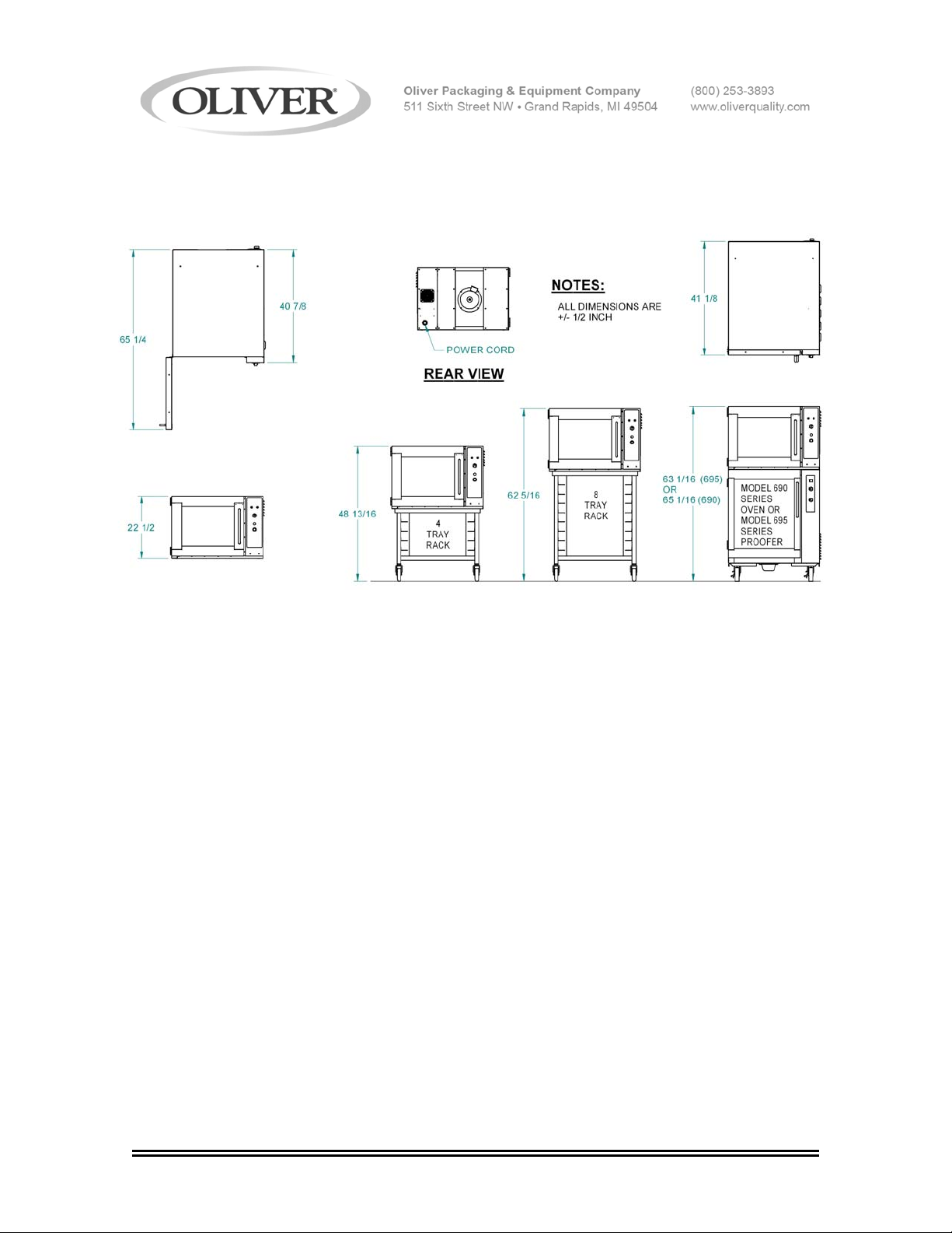
Space Requirements:
Single: 41-1/8” Deep x 33” Wide x 22-1/2” high.
Single with short stand and casters: 48-13/16” high.
Single with tall stand and casters: 62-5/16” high
Stacked 688 oven & 695 Proofer with casters: 63-1/16” high
Stacked 688 & 690 ovens with casters: 65-1/16” high
Clearance:
Left side = 2”.
Right side = 12” in a fixed location, (to have access to electrical components), or
2” when mounted on another unit which has casters.
Back side = 4” to allow for proper motor ventilation and electrical connection.
Net Weight: Approximately 300 pounds.
Shipping Weight: Approximately 350 pounds.
0688S20003 2-2
MODEL 688-N
INSTALLATION / SETUP
Inspection
Before accepting delivery inspect the carton and machine for damage. Note any damage
found on the shipping documents. Remember shipping damage is not
warranty, and is the responsibility of the carrier. Also report the damage to the dealer
from which the oven was purchased for further direction and assistant in filing a claim with
the carrier.
Location Selection
Select a location where the oven will be used. The oven must be set on a flat level
surface. It should have a grounded power supply of the same rating as shown on the
nameplate located on the rear of the oven and this power supply must be capable of
carrying the load that the oven will put on it (See “Electrical Connection” below).
Ovens mounted on other units with casters should be placed so that they have a minimum
of two inches on each side and a minimum of four inches in the rear of the oven to provide
for proper motor ventilation and electrical connection.
Ovens without casters should be placed so that there is a minimum of two inches on all
sides, except for the side with the electrical panel, (right side), which should have a
minimum of twelve inches. The rear of an oven without casters should be a minimum of
four inches away from adjacent surfaces to allow room for the electrical connection and
motor ventilation.
Sealing Oven to Mounting Surface
covered by your
CAUTION
MAKE SURE THAT THE MOUNTING SURFACE IS ABLE TO SUPPORT THE WEIGHT
OF THE OVEN WHICH IS APPROXIMATELY 300 POUNDS PLUS AN ADEQUATE
SAFETY FACTOR BEFORE PLACING IT ON THE SURFACE.
The oven must be
For the purpose of sealing the unit a tube of NSF/FDA approved silicone sealant has been
provided with your unit. Apply, to the surface that the oven will rest on, a continuous bead
of sealant approximately 1/2 inch in from each of the four sides of the oven. After the
oven has been placed over this bead apply a second generous continuous bead at the
joint where the oven contacts the mounting surface thus totally sealing the bottom of the
oven to that surface.
0688S20004 3-1
sealed to the mounting surface to comply with local sanitation codes.
MODEL 688-N
Oven Setup
Ovens may be mounted to a fixed surface, attached to an “Oliver” oven rack with casters
or stacked on either a Oliver Model 690 Oven or and Oliver Model 695 Proofer. For
associated mounting heights for the above options see page 2-2.
CAUTION
USE CARE WHENEVER MOVING OVENS MOUNTED ON RACKS AS THEY ARE TOP
HEAVY AND PRESENT A TIPPING HAZARD.
Ovens attached to “Oliver” oven racks must be
Stacked units should be setup as shown on page 2-2 being sure that the alignment pins
on the top of the lower unit are securely positioned into the holes in the base of the upper
oven.
Electrical Connection
securely fixed to the rack with bolts.
WARNING
THE OVEN MUST BE CONNECTED TO A PROPERLY GROUNDED ELECTRICAL
SOURCE OF THE SAME RATING AS THE MACHINE. FAILURE COULD RESUL T IN
AN ELECTRICAL SHOCK WHICH MAY CAUSE INJURY OR DEATH.
WARNING
ALL WIRING AND ELECTRICAL REPAIRS SHOULD BE DONE BY A QUALIFIED
ELECTRICIAN. FAILURE TO DO SO MAY CAUSE SERIOUS INJURY OR DEATH.
CAUTION
SPECIAL HEAVY DUTY ELECTRICAL SERVICES AND WALL DISCONNECTS MUST
BE PROVIDED FOR SAFE OPERATION OF THE OVEN.
The following service requirements are recommended, dependent on the voltage of the
unit you have purchased. Your oven’s requirements can be found on the nameplate
attached to its rear surface.
0688S20004 3-2
MODEL 688-N
Electrical Connection (continued)
For voltages other than those shown below please contact the factory. Check the voltage
at the electrical disconnect before proceeding to the next step.
480 Volts = 20 Amp service
375 Volts = 20 Amp service
240 Volts = 30 Amp service
208 Volts = 30 Amp service
The oven is shipped from the factory with a power cord, which does not include a plug.
The power cord should be wired to a disconnect enclosure which is accessible from the
oven work area, leave at least two feet of slack so that access can be gained to the ovens
back and right side. A plug may be used between the disconnect enclosure and the oven
instead of hard wiring as described above. This makes sliding the oven out for service
more convenient. Whatever method is used the oven should be wired in a manner which
would conform to the U.S. “National Electric Code”.
CAUTION
FANS MUST ROTATE IN THE CLOCKWISE DIRECTION FOR PROPER AIRFLOW.
IMPROPER DIRECTION MAY CAUSE UNEVEN BAKES AND LONGER BAKING TIMES.
Check fan rotation for clockwise direction. After the oven has been “Set Up” and
connected to the electrical service do the following to check the rotation of the fans. Use
the following sequence to start the oven to check fan rotation direction:
• Turn the main power switch on, (green button). The oven blower motor should
start. Once started the fan rotation can be checked.
• Once complete, turn the main power switch off, (red button).
If the rotation is incorrect remove and interchange any two of the three incoming power
leads (red, white and black), at the plug or disconnect enclosure and retest.
Venting
The gap between the door and the housing of the model 688 oven is designed to be the
vent for the oven. SOME STEAM MAY ESCAPE THROUGH THE FRONT DOOR
GASKET.
0688S20004 3-3
MODEL 688-N
WARNING
HOT STEAM ESCAPING WHILE OPENING DOOR CAN CAUSE SEVERE BURNS.
STAND BACK WHILE OPENING DOOR TO AVOID INJURY.
Test Cycle
After completing the Set Up, and Electrical connections, you may wish to run the oven
through a test cycle to verify that everything is ready. Use the following sequence to test
the oven.
• Turn the main power switch on, (green button). The fan should start.
• Adjust temperature to 350 degrees F using thermostat. The heat light should
• Once the oven reaches the set temperature the heating elements should cycle on
• The gap between the door and the housing of the model 688 oven is designed to
• Once complete, turn the main power switch off, (red button).
illuminate, then extinguish when oven reaches temperature.
and off as indicated by the heat light.
be the vent for the oven. SOME STEAM MAY ESCAPE THROUGH THE FRONT
DOOR GASKET.
0688S20004 3-4
MODEL 688-N
OPERATING INSTRUCTIONS
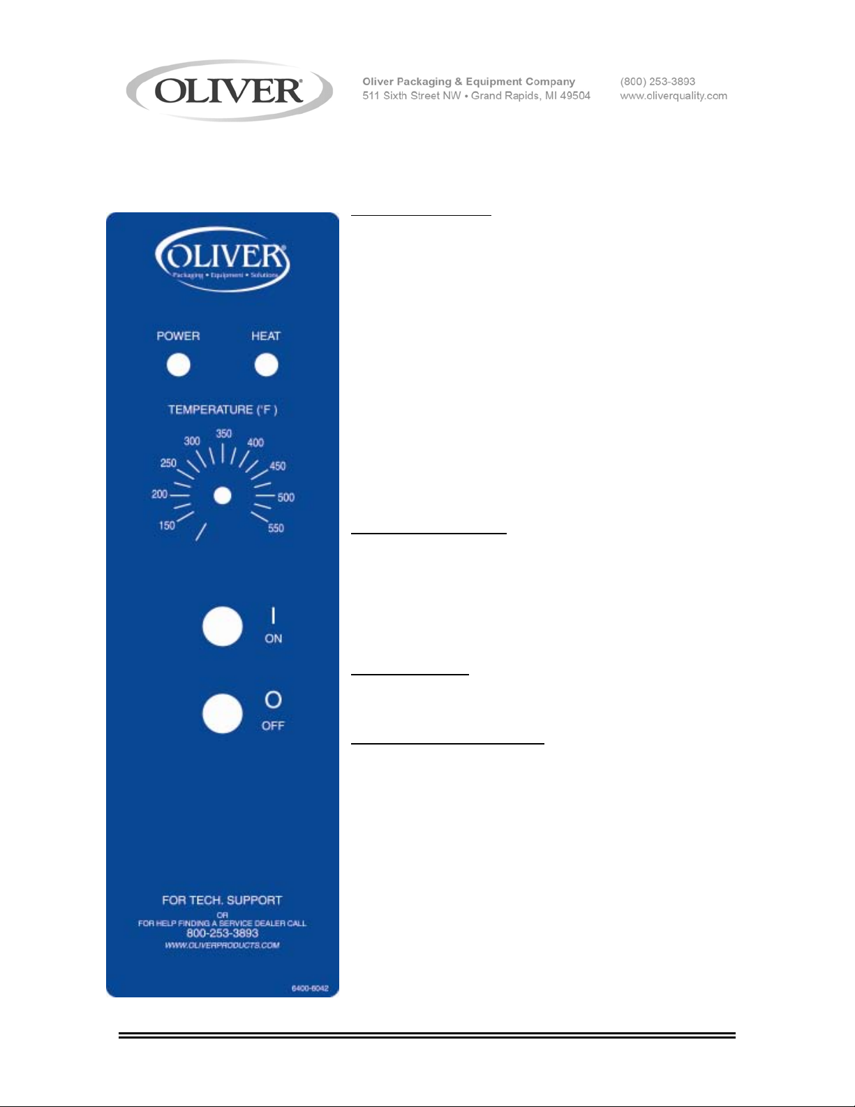
Beginning Operation
First turn the oven on by pressing the green “On”
button. The green “Power” lamp should be illuminated,
oven blower will start, and heater will be turned on if
temperature setting is higher than the temperature
inside of oven.
Green “Power” lamp is illuminated anytime units is on.
Red “Heat” lamp is illuminated anytime heater is on.
(When oven is up to temperature the lamp is off)
lamp will continue to cycle on/off with heaters.
Oven blower and heater will turn off anytime door is
opened regardless of temperature. Normal blower and
heater operation will resume after door is closed.
Adjusting Temperature
Adjust the temperature of the oven by turning dial to
correspond to the temperature desired. Allow oven to
reach temperature before baking. If adjusting to a lower
temperature, it may be necessary to allow oven to cool
by leaving door open for a few minutes.
Turning Oven Off
Turn oven off by pressing the red “Off” button.
Adjusting Moveable Shelves
6 moveable shelves are provided – 3 (RH) right hands,
3 (LH) left hands.
For 2 shelf operation – remove all moveable shelves.
For 3 shelf operation – install 1 RH and 1 LH moveable
shelves in center location.
For 4 shelf operation – install 2 RH and 2 LH moveable
shelves in locations closest, but not in, center.
For 5 shelf operation – install 3 RH and 3 LH moveable
shelves in center and the two outermost locations.
Shelves should be equally spaced for the best possible
bake.
0688S20005 4-1
MODEL 688-N
TROUBLESHOOTING
WARNING
TROUBLE SHOOTING OF ELECTRICAL EQUIPMENT SHOULD BE PERFORMED BY
QUALIFIED PERSONNEL ONLY. ELECTRICAL POTENTIAL IS GREAT ENOUGH TO
CAUSE INJURY OR DEATH.
CAUTION
BEFORE WORKING ON A OVEN WHICH HAS BEEN RECENTLY USED
ALLOW SUFFICIENT TIME FOR IT TO COOL TO PREVENT BURNS.
No Power – Oven Will Not Start.
• The machine is not plugged in.
• There is no power available at the outlet/disconnect
• A fuse has blown.
• The transformer has failed. (Control panel only)
• Oven temperature is too high. (Your oven comes with a high temperature limit switch
set at approx. 600 °F. This switch will reset when the oven has cooled.)
• Motor has overheated. (The blower motor is equipped with an internal thermal
switch). Turn the oven off and try to restart after the motor has cooled.
Possible causes:
1.) The motor bearing or winding has failed.
2.) Something is binding the motor or blower fan.
3.) The rear of the oven lacks sufficient clearance to allow proper air circulation.
No Heat or Oven Heats Slowly
A cooled dry empty oven can be heated from room temperature to 300 °F in four to six
minutes. If the oven is not meeting this specification, check the following.
• Check the fuses
• Check the two contactors.
• Check heater bank continuity.
(continued)
0688S20006 5-1
 Loading...