

Oliver 6510 Owner's Manual
Single Spindle Automatic Dovetailer
Owner’s Manual
Oliver Machinery M-6510 09/2015
Seattle, WA Copyright 2003-2015
info@olivermachinery.net www.olivermachinery.net

Warranty
Oliver makes every effort possible to assure that its equipment meets the highest possible
standards of quality and durability. All products sold by Oliver are warranted to the original
customer to be free from defects for a period of 2 (two) years on all parts, excluding electronics
and motors, which are warranted for 1 year. Oliver’s obligation under this warranty shall be
exclusively limited to repairing or replacing (at Oliver’s option) products which are determined by
Oliver to be defective upon delivery F.O.B. (return freight paid by customer) to Oliver, and on
inspection by Oliver. This warranty does not apply to defects due, directly or indirectly, to misuse,
abuse, negligence, accidents, unauthorized repairs, alterations, lack of maintenance, acts of
nature, or items that would normally be consumed or require replacement due to normal wear. In
no event shall Oliver be liable for death, personal or property injury, or damages arising from the
use of its products.
Warning
Read this manual thoroughly before operating the machine. Oliver Machinery disclaims any
liability for machines that have been altered or abused. Oliver Machinery reserves the right to
effect at any time, without prior notice, those alterations to parts, fittings, and accessory
equipment which they may deem necessary for any reason whatsoever.
For More Information
Oliver Machinery is always adding new Industrial Woodworking products to the line. For
complete, up-to-date product information, check with your local Oliver Machinery distributor, or
visit www.olivermachinery.net

1.SAFETY INSTRUCTION 1-1
1.1. SAFETY REGULATIONS
1.1.1. GENERAL SAFETY RULES
Do not attempt to operate until you have read thoroughly
and understand completely all instructions, rules, etc.
contained in this manual. Failure to comply can result in accidents involving fire,
electric shock, or serious personal injury. Keep owners manual and review
frequently for continuous safe operation.
1. KNOW YOUR MACHINE.
For your own safety, read the owner's manual carefully. Learn its application and
limitations as well as specific potential hazards pertinent to this machine.
2. KEEP GUARDS IN PLACE AND IN WORKING ORDER.
3. REMOVE ADJUSTING KEYS AND WRENCHES.
For habit of checking to see that keys and adjusting wrenches are remove from the
machine before turning it on.
4. KEEP WORK AREA CLEAN.
Cluttered areas and benches invite accidents.
5. DO NOT USE IN DANGEROUS ENVIRONMENTS.
Do not use power tools in damp or we locations, or expose them to rain. Keeps
work area well illuminated.
6. KEEP CHILDREN AWAY.
All visitors should be kept at a safe distance from work area.
7. MAKE WORKSHOP CHILDPROOF.
With padlocks, master switches, or by removing starter keys.
8. DO NOT FORCE THE MACHINE.
It will do the job better and be safer at the rate for which it was designed.
9. USE THE RIGHT TOOLS.
Do not force the machine or attachments to do a job for which they were not
designed.
10. WEAR PROPER APPAREL.
Avoid loose clothing, gloves, neckties, rings, bracelets, or jewelry, which could be
caught in moving parts. Nonslip footwear is recommended. Wear protective hair
covering to contain long hair.

1.SAFETY INSTRUCTION 1-2
11. SECURE WORK.
Use clamps or a vice to hold work when practical. It is safer than using your hand
and frees both hands to operate the machine.
12. DO NOT OVERREACH.
Keep proper footing and balance at all times.
13. MAINTAIN MACHINE IN TOP CONDITION.
Keep machine clean for best and safest performance. Follow instructions for
lubricating and changing accessories.
14. DISCONNECT MACHINE FROM POWER SOURCE.
Before servicing and when changing accessories, or when mounting and
remounting motor.
15. USE RECOMMENDED ACCESSORIES.
Consult the owner's manual for recommended accessories.
16. NEVER LEAVE MACHINE RUNNING UNATTENDED. TURN PO WER OFF.
17. Protective guards and shields must be in place at all times unless that specific part
requires servicing.
18. Never clean or remove chips while the machine is running.
19. Do not remove or alter warning labels and replace any that become obscured.
1.1.2. ADDITIONAL SAFETY RULES FOR AUTOMATIC MILLING
MACHINE
1. Proper operation of this machine requires the specific knowledge of the following
instructions and of the risks consequent to improper utilization.
2. Therefore only qualified and authorized personnel must operate the machine. The
operator will be trained on the proper use of the equipment, its protection devices
and accessory tools.
3. Safe operation of the machine is guaranteed only for the functions and materials
indicated in these user's instructions. We decline any responsibility if the machine is
used for purposes outside those indicated in the user's instructions or not complying
with them.

1.SAFETY INSTRUCTION 1-3
4. We declines any responsibility related to equipment safety, reliability and
performance if warnings and instructions contained in this manual are not observed,
with specific reference to: Equipment utilization, routine and emergency
maintenance, repair.
5. The manufacturer declines any responsibility if the machine is not properly
connected to the equipotent ground line or if the appropriate circuit breakers are not
installed and coordinated between electrical power lines and the machine,
according to the above Regulations.
6. All protection devices are provided and mounted on the machine appropriately. We
recommend complying with the periodical routine and extraordinary maintenance
scheduled for the protection devices and the entire machine.
7. The operator must wear appropriate working clothes from a safety and operational
point of view. Bracelets, necklaces and other apparel that can get caught in the
machine will not be allowed.
8. It is important to think about potential risks and consequences before approaching
hands to the most dangerous zones such as: Piece locking pistons, Mill cutter,
Cams slide, Electrical control panel.
9. Keep the machine power off when not in use.
10. The machine does not include its own illumination. User must provide appropriate
lighting of working area.
11. The machine may not be operated in environments polluted by gas and flammable
compounds.
12. All operations of adjustment and tuning will be performed with machine power off.

3. INSTALLATION 3-1
3.1. SAFETY RULES FOR MACHINE LIFTING
1. Pay special attention to the balance of the machine while lifting.
2. Use a forklift or a hydraulic hand pallet truck with sufficient loading capacity to lift the
machine.
3. Have another person help guide the way when lifting the machine.
4. The forks of forklift must protrude from under the machine.
5. The forklift must only be driven by an experienced forklift driver.
3.2. SELECTION OF LOCATION
Requirement of operating environment the operating temperature for this machine should
be between +5℃ and +40℃,while the relative humidity should not exceed 50% at a
maximum temperature of +40℃.
3.3. LIFTING THE MACHINE
1. A forklift or a hydraulic hand pallet truck can lift the machine.
2. Their forks should insert through the machine bottom.
3. Attention should be paid to the balance of the machine while lifting.
4. The weight of the machine is listed below.
Model Machine weight
Forklift or hydraulic hand pallet truck capacity
JD-75 500 Kg 1 ton

3. INSTALLATION 3-2
3.4. POWER SUPPLY REQUIREMENT
Insufficient voltage from factory power source may affect the power output of the motor.
It is important to connect this machine to the correct voltage in the factory power source.
Use only an independent power source.
Table for power supplies requirement:
Kw Voltage Current Breaker capacity
2.3 Kw 220 V, 60 Hz 9.5 A 15A 3.5mm2
2.3 Kw 400 V, 50 Hz 5.2 A 15A 3.5mm2
2.3 Kw 575 V, 60 Hz 9.5 A 15A 3.5mm2
Wire size
3. INSTALLATION 3-3
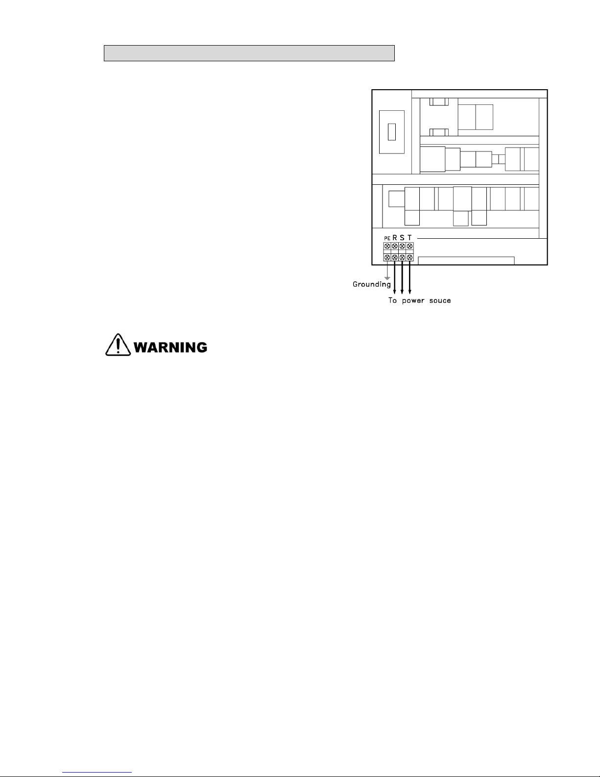
3.6. CONNECT POWER SOURCE WIRES
1. Before connecting the power wires make
sure the voltage between the machine and
your factory power source is the same.
2. Take out the electrical cover (A) at the
machine base outside.
3. Connect the power wires to the R.S.T.
4. The machine must be properly grounded to
prevent possible injury from electrical shock.
5. Qualified electrical personnel should
perform all electrical connections.
Grounding should be based on the local
regulations.
3. INSTALLATION 3-4
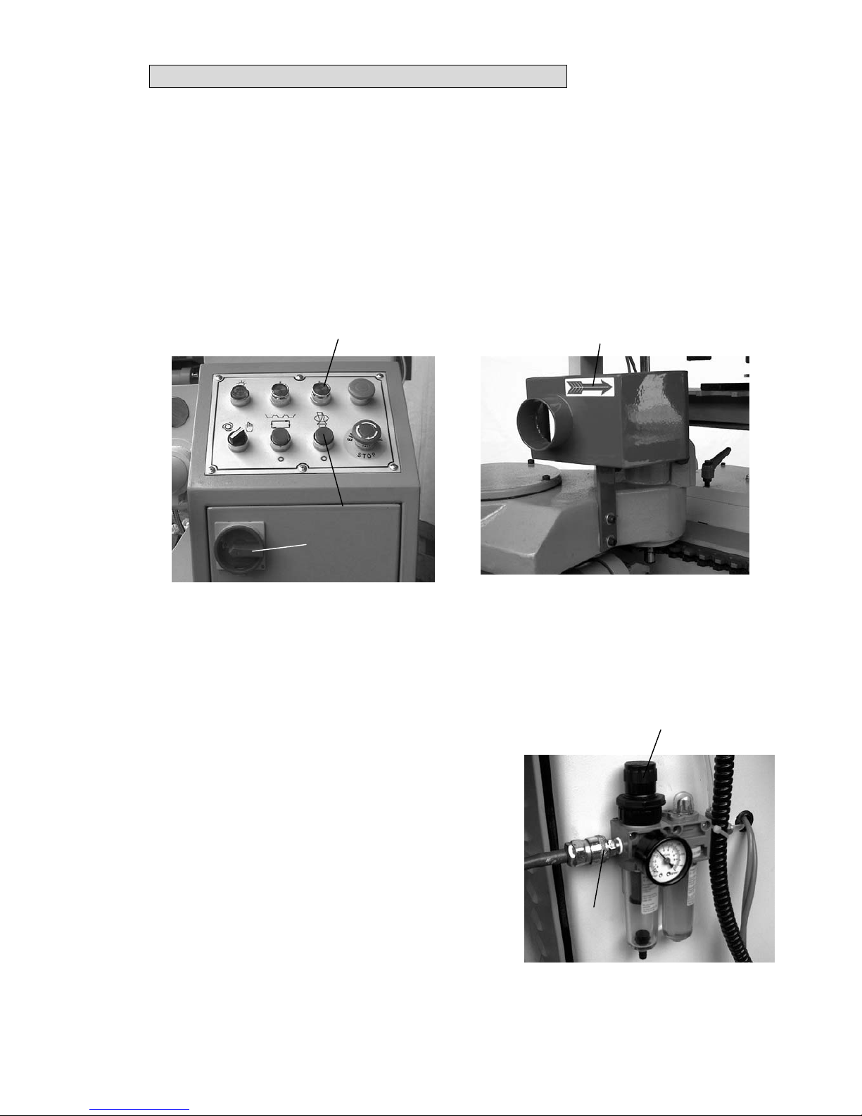
3.7. CHECK POWER WIRES CONNECTION
1 After the power wires have been connected it is necessary to check if the power wires
are connected to the correct connection points.
2 Turn on the power switch (A) on the control cabinet.
3 Verify proper rotation of mill cutter by starting (B) and stopping (C) the machine
immediately afterwards; then the mill cutter should be rotate according to the indicate
direction (D). If not, swap two phases of the electrical connection.
3.8. COMPRESSED-AIR CONNECTION
Some of the individual units function electro
pneumatically. Therefore, compressed air must be
connected on the machine. The “F.R.L” unit is
installed at the machine front. Connect the adapters
(A) to the compress air source.
The nominal pipe diameter is 10 mm.
Operation pressure is at 6 bar, pulling and turning
knobs (B) to adjust the air pressure.
A
B
C
A
B
D
3. INSTALLATION 3-5
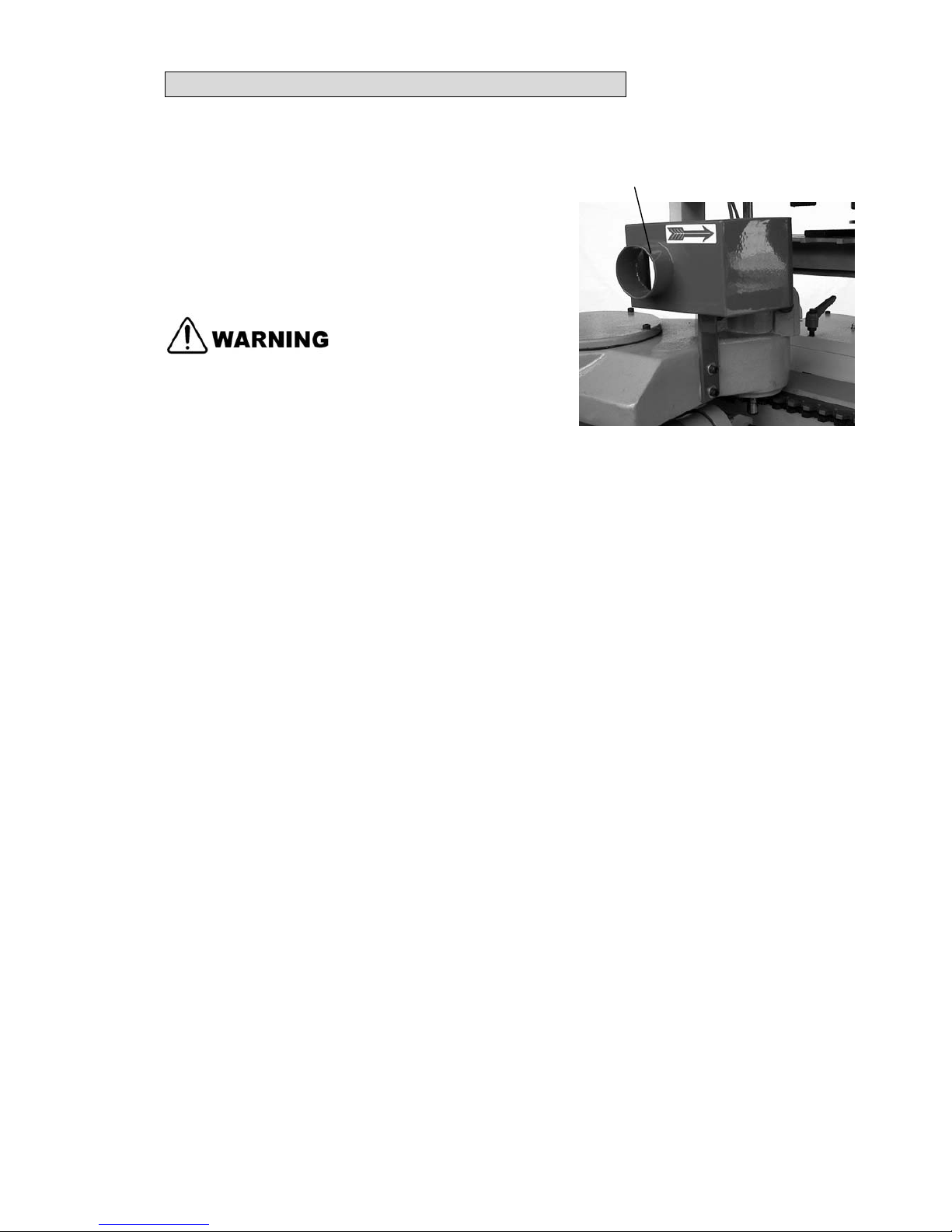
3.9. CONNECT DUST COLLECTION SYSTEM
1. There is a dust hood provided on the mill
cutter unit for sucking dust from the machine.
2. Fit the flexible hose to the dust hood (A) and
connect it to the dust collector.
3. The outlet diameter for dust hood is 60mm.
Do not perform milling operations until the
dust collection system is started.
A
4. OPERATION 4-1
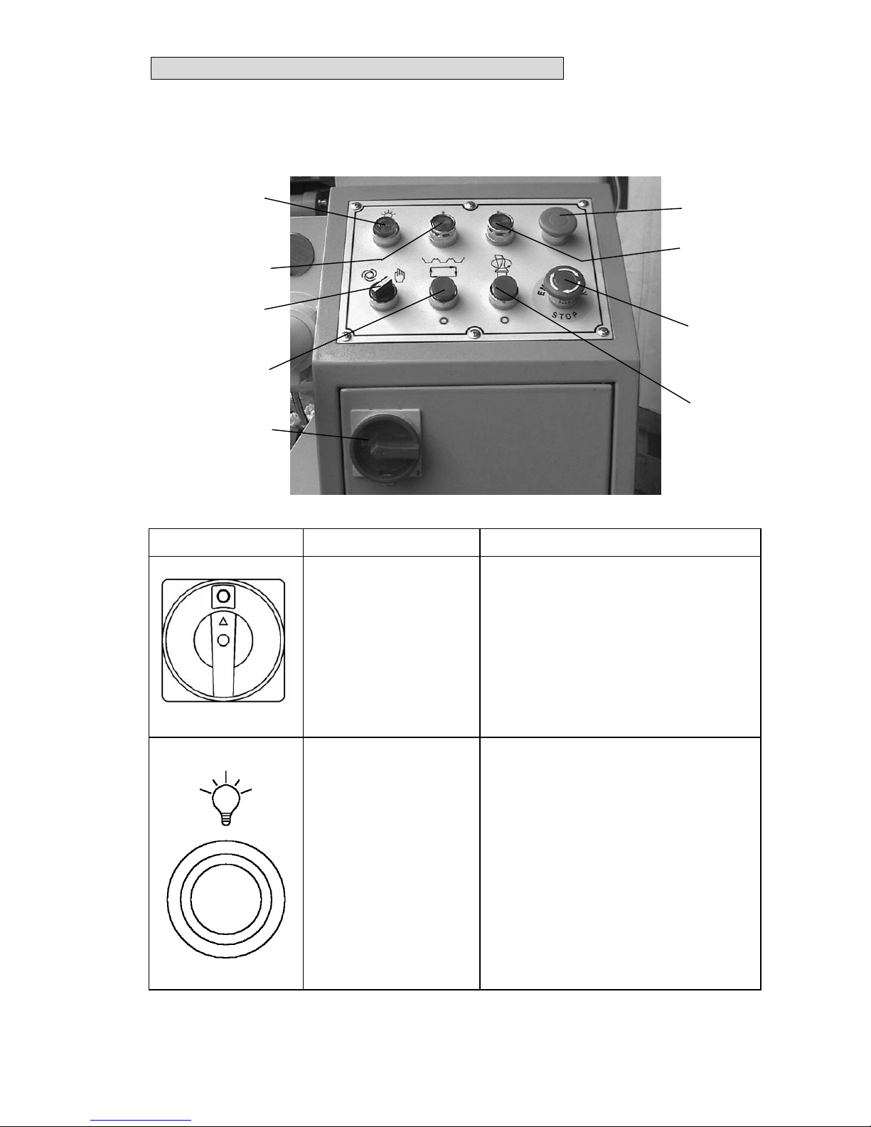
4.1. CONTROLS
4.1.1. SWITCHES FUNCTION ON ELECTRICAL CONTROL PANEL
SWITCH NAME FUNCTION
1
QS1
POWER SOURCE
SWITCH
When turns the switch to the ON
position the machine is connected
to the power and is ready to
operate.
When the machine is not in use.
Turn the switch to the OFF position.
2
HL1
POWER LAMP
When the power source switch is
turned on, this lamp will light up,
indicating that the machine is under
power.
3
5
2
6
4
1
7
9
8
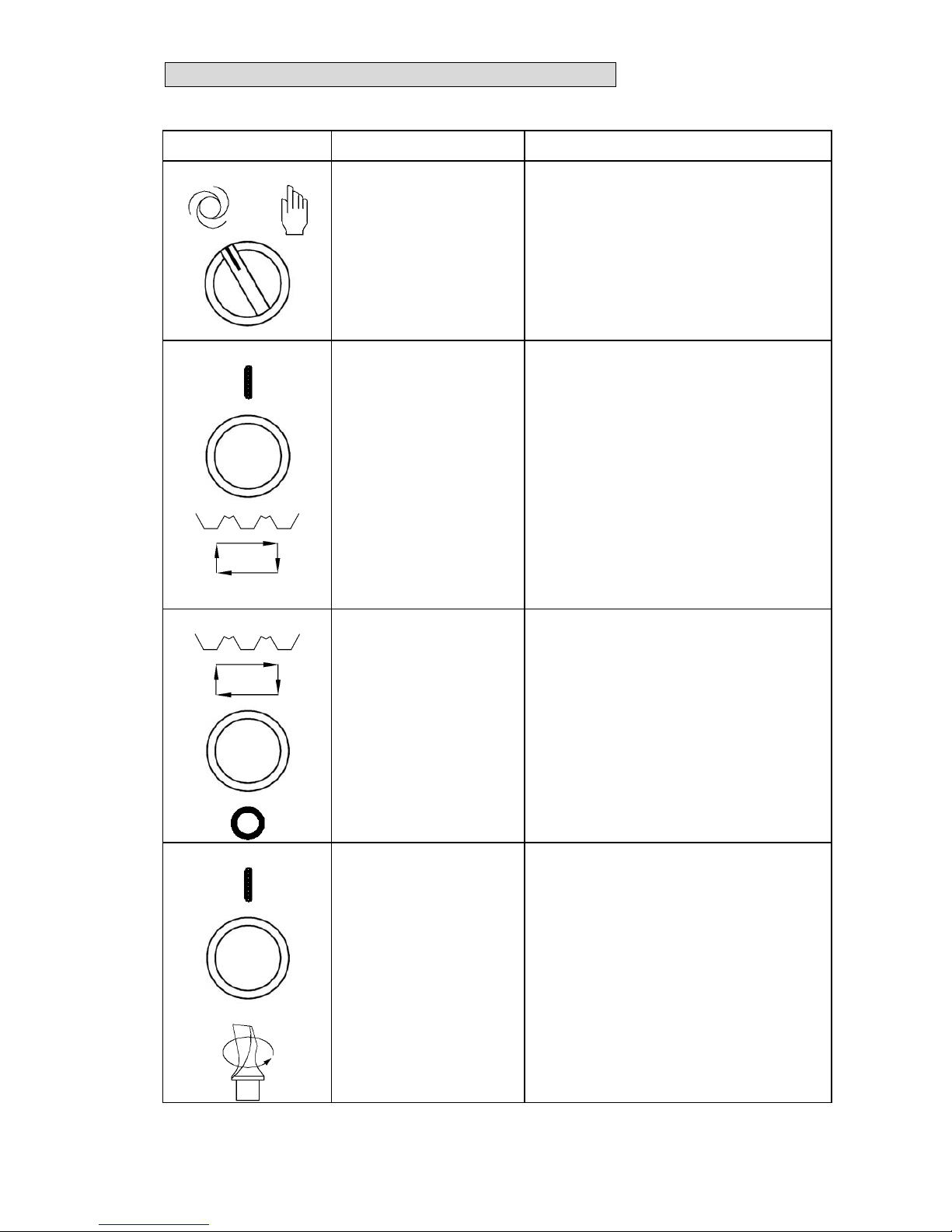
4. OPERATION 4-2
SWITCH NAME FUNCTION
3
OPERATE MODE
SELECTION SWITCH
Set the switch left for mill head travel
automatic cycle and the switch rights
for mill head travel single cycle.
4
SA2
MOTION MOTOR
START SWITCH
Press this switch for starting the
motion motor. The switch light
comes on.
5
MOTION MOTOR
STOP SWITCH
Press this switch to stop the motion
motor.
6
MILLING SPINDLE
START SWITCH
Press this switch for starting the
milling spindle. The switch light
comes on.
 Loading...