


INDEX
Chap. 1 GENERAL INFORMATION
1.1 |
General information |
page 26 |
|
1.2 |
Symbols |
|
page 27 |
|
1.2.1 |
Editorial pictograms |
page 27 |
|
1.2.2 |
Safety pictograms |
page 27 |
1.3 |
Technical data |
page28 |
|
|
1.3.1 |
Overall dimensions |
page 28 |
|
1.3.2 |
Technical features |
page 28 |
|
1.3.3 |
Technical notes |
page 28 |
|
1.3.4 |
Proper use |
page 28 |
1.4 |
List of accessories supplied |
page 29 |
|
|
1.4.1 |
Storage |
page 29 |
|
1.4.2 |
Receipt and unpacking |
page 29 |
Chap. 2 INSTALLATION
2.1 |
Instructions for installation |
page 30 |
|
2.2 |
Selection of position of the unit |
page 30 |
|
|
2.2.1 |
Choice of best position for installing the air conditioner |
page 30 |
|
2.2.2 |
Dimensions and features of site where air conditioner is installed |
page 30 |
2.3 |
Installation of the unit |
page 31 |
|
|
2.3.1 |
Drilling the wall |
page 31 |
|
2.3.2 |
Provision for draining condensate for machines with heat pump |
page 33 |
|
2.3.3 |
Installation of air pipes and external gratings |
page 33 |
|
2.3.4 |
Power supply connection |
page 34 |
|
2.3.5 |
Fitting the unit on bracket |
page 35 |
2.4 |
Preparation for assembly/installation wall top part |
page 35 |
|
|
2.4.1 |
Introduction |
page 35 |
|
2.4.2 |
Removal of front casing |
page 35 |
|
2.4.3 |
Preparation of unit |
page 36 |
2.5 |
Working tests and identification of possible malfunction |
page 36 |
|
|
2.5.1 |
Evacuation of condensation water in case of emergency |
page 38 |
2.6 |
Periodical maintenance |
page 38 |
|
Chap. 3 USE AND MAINTENANCE (for the user)
3.1 |
Important Recommendations |
page 39 |
|
|
3.2 |
Names of parts |
page 39 |
|
|
|
3.2.1 |
List of Units |
page 39 |
|
|
3.2.2 |
Description of signal console |
page 39 |
|
3.3 |
Control of Air Conditioner using the remote control unit |
page 40 |
|
|
|
3.3.1 |
Remote control |
page 40 |
|
|
3.3.2 |
Insertion of batteries |
page 40 |
|
3.4 |
Remote control |
page 40 |
|
|
|
3.4.1 |
Description of the remote control |
page 40 |
|
|
3.4.2 |
Switching on and control of operation |
page 41 |
|
|
3.4.3 |
Switching the unit on and off (button T1) |
page 41 |
|
|
3.4.4 |
Automatic Operation (button T2) |
page 41 |
|
|
3.4.5 |
Cooling function |
page 41 |
|
|
|
|||
|
3.4.6 |
Dehumidifier only |
page 42 |
|
|
3.4.7 |
Fan only |
page 42 |
|
|
3.4.8 |
Heating function (only models with heat pump) |
page 42 |
|
|
3.4.9 |
Control of air flow direction |
page 42 |
|
|
3.4.10 |
Control of fan speed |
page 43 |
|
|
3.4.11 |
External air intake |
page 43 |
|
|
3.4.12 |
Night operation |
page 44 |
|
|
3.4.13 |
Setting programs for operation |
page 44 |
|
|
3.4.14 |
Setting of correct time |
page 44 |
|
|
3.4.15 |
Setting of time schedules for 1st and 2nd Operating Program (PROGR. 1 and PROGR. 2) |
page 45 |
|
|
3.4.16 |
Starting and stopping operating programs |
page 45 |
|
|
3.4.17 |
Resetting all functions of remote control |
page 46 |
|
|
3.4.18 |
Control of Air Conditioner if remote control is not available |
page 46 |
|
3.5 |
Maintenance |
page 46 |
|
|
|
3.5.1 |
Cleaning air filter |
page 46 |
|
3.6 |
Troubleshooting |
page 47 |
|
|
|
3.6.1 |
Functional aspects that should not be mistaken for malfunctions |
page 47 |
|
3.7 |
Recommendations for energy savings |
page 47 |
|
|
3.8 |
Troubleshooting |
page 48 |
|
|
UNICO-HE |
|
25 |
|
CHAP. 1 GENERAL INFORMATION
CHAP. 1.1 GENERAL INFORMATION
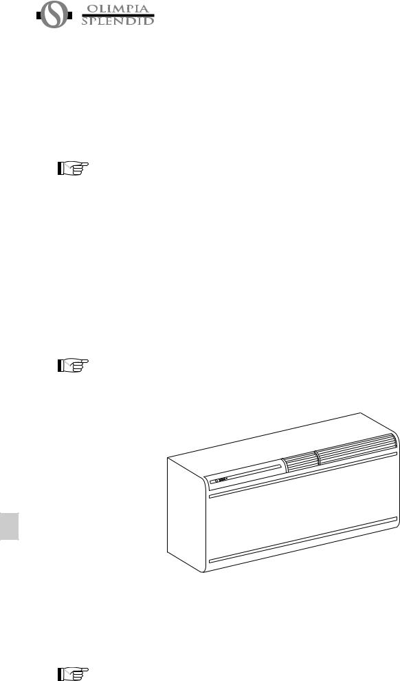
We wish to thank you, first of all, for purchasing an air-conditioner produced by our company.
We are sure you will be happy with it because it represents the state of the art in the technology of home air conditioning.
This manual serves to provide you with the instructions and explanations you need to make the best possible use of your air-conditioner.
We suggest that you read it carefully before starting to use the appliance.
By following the instructions and suggestions provided in the manual, your air-conditioner will give you years of smooth operation and comfort at the lowest cost in terms of power consumption.
ATTENTION
The manual is divided into 4 sections or chapters:
CHAP. 1 GENERAL INFORMATION
Contains information for the specialized installer and end user.
The information, technical data and important warnings must be known before installing and using the air-conditioner.
CHAP. 2 INSTALLATION
Contains information exclusively intended for the specialized installer.
The information contained in this chapter is necessary for installation of the air conditioner.
If the air-conditioner is installed by personnel lacking the necessary qualifications and specialization this invalidates the warranty.
CHAP. 3 USE AND MAINTENANCE (by user)
Contains all information and instructions for proper use and programming of the air-conditioner, as well as instructions for simple maintenance.
CHAP. 4 TROUBLESHOOTING
Helps user in case of malfunctions.
This document is restricted in use to the terms of the law and may not be copied or transferred to third parties without the express authorization of the manufacturer, OLIMPIA SPLENDID.
Our machines are subject to change and some parts may appear different from the ones shown here, without this affecting the text of the manual in any way.
Read this manual carefully before performing any operation (installation, maintenance, use) and follow the instructions contained in each chapter.
THE MANUFACTURER IS NOT RESPONSIBLE FOR DAMAGES TO PERSONS OR PROPERTY CAUSED BY FAILURE TO FOLLOW THE INSTRUCTIONS IN THIS MANUAL.
The manufacturer reserves the right to make any changes it deems advisable to its models, although the essential features described in this manual remain the same.
The installation and maintenance of air-conditioners like this one may be hazardous as they contain a cooling gas under pressure as well as powered parts.
Therefore, the installation, first startup and subsequent maintenance should be carried out exclusively by authorized, qualified personnel.
26 |
|
UNICO-HE |
|
Routine maintenance of the filters and general external cleaning can be done by the user as these operations are not difficult or dangerous.
During installation and maintenance, respect the precautions indicated in the manual, and on the labels applied inside the units, as well as all the precautions suggested by good sense and by the safety regulations in effect in your country.
Always wear gloves and protective goggles when performing any operations on the refrigerating side of the units.
Air conditioners must not be installed in places containing inflammable gasses, explosive gasses, or in very humid environments (laundries, greenhouses, etc.), or in places where there are machines that generate very great heat.
In case of replacement of parts, use only original OLIMPIA SPLENDID parts.
IMPORTANT!
To prevent any risk of electrocution, always disconnect the main circuit breaker before making electric connections or performing any maintenance on the units.
The following instructions must be made known to all personnel involved in the machine’s transport and installation.
CHAP. 1.2 SYMBOLS
The pictograms in the next chapter provide the necessary information for correct, safe use of the machine in a rapid, unmistakable way.
1.2.1 Editorial pictograms
Service
- Refers to situations in which you should inform the SERVICE department in the company:
CUSTOMER TECHNICAL SERVICE.
Index
- Paragraphs marked with this symbol contain very important information and recommendations, particularly as regards safety.
Failure to comply with them may result in:
-danger of injury to the operators
-loss of the warranty
-refusal of liability by the manufacturer.
Raised hand
- Refers to actions that absolutely must not be performed.
1.2.2 Safety pictograms
Danger of high voltage
- Signals to the personnel that the operation described could cause electrocution if not performed according to the safety rules.
Generic danger
- Signals to the personnel that the operation described could cause physical injury if not performed according to the safety rules.
Danger due to heat
- Signals to the personnel that the operation described could cause burns if not performed according to the safety rules.
UNICO-HE |
|
27 |
|
CHAP. 1.3 TECHNICAL DATA
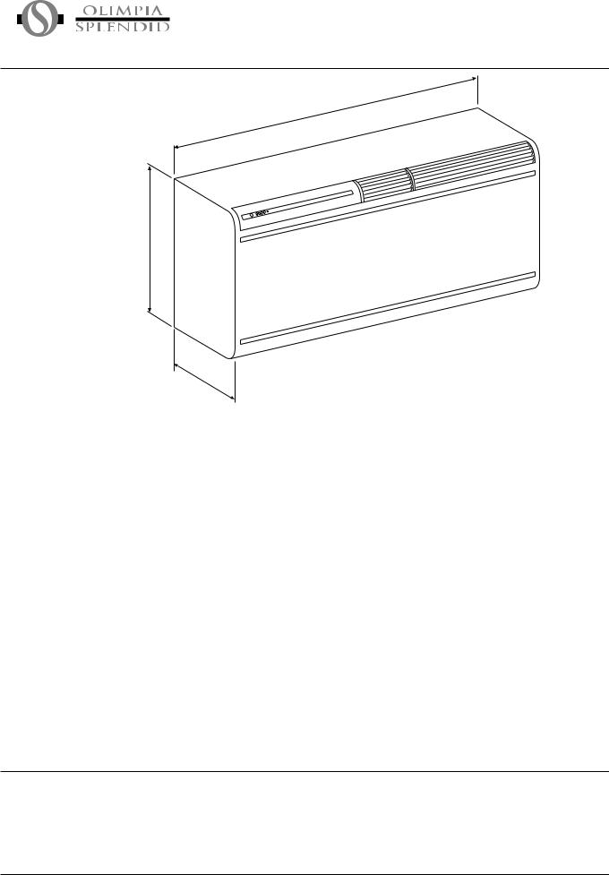
1.3.1 Overall dimensions
400
870
|
|
280 |
|
|
|
|
|
|
|
|
|
|
|
|
|
|
|
|
|
1.3.2 |
|
|
|
|
|
|
|
|
Technical |
|
|
|
|
|
|
|
|
features |
|
|
UNICO 8.5 HE |
UNICO 8.5 HP HE |
UNICO 11 HE |
UNICO 11 HP HE |
|
|
|
|
|
|
|
|
|
|
|
|
Cooling capacity |
kW |
2,1 |
2,1 |
2,45 |
2,45 |
|
|
|
Heating capacity |
kW |
-- |
1,9 |
-- |
2,035 |
|
|
|
Capacity absorbed during cooling |
W |
790 |
790 |
1100 |
1100 |
|
|
|
Absorption during cooling |
A |
3,47 |
3,47 |
4,83 |
4,83 |
|
|
|
Absorbed power during heating |
W |
-- |
720 |
-- |
1080 |
|
|
|
Absorption during heating |
A |
-- |
3,16 |
-- |
4,75 |
|
|
|
Max. absorbed power (*) |
W |
930 |
930 |
1320 |
1320 |
|
|
|
Maximum absorption (*) |
A |
4,12 |
4,12 |
5,85 |
5,85 |
|
|
|
E.E.R. (during cooling) |
|
2,66 |
2,66 |
2,23 |
2,23 |
|
|
|
Energy efficiency class during cooling |
|
A |
A |
C |
C |
|
|
|
C.O.P. (during heating) |
|
-- |
2,64 |
-- |
1,88 |
|
|
|
Energy efficiency class during heating |
|
-- |
C |
-- |
F |
|
|
|
Annual energy consumption in cooling mode |
kWx500h |
395 |
395 |
550 |
550 |
|
|
|
Dehumidification capacity |
l/h |
1 |
1 |
1,2 |
1,2 |
|
|
|
Cooling Gas |
|
R410a |
R410a |
R410a |
R410a |
|
|
|
Power supply voltage |
V-Hz |
230-50 |
230-50 |
230-50 |
230-50 |
|
|
|
Internal unit ventilation speed |
Num. |
3 |
3 |
3 |
3 |
|
|
|
Maximum delivery of air during cooling (indoor unit) |
m3/h |
350 |
350 |
390 |
390 |
|
|
|
Maximum air delivery OUTDOOR UNIIT |
m3/h |
480 |
480 |
550 |
550 |
|
|
|||||||
|
|
|
Dimensions of indoorl unit (Lxhxw) |
mm |
870x400x280 |
870x400x280 |
870x400x280 |
870x400x280 |
|
|
|
Weight of indoor unit |
kg |
43 |
43 |
46 |
46 |
|
|
|
Weight of outdoor unit |
kg |
-- |
-- |
-- |
-- |
|
|
|
Maximum range of remote control |
m |
8 |
8 |
8 |
8 |
(*)Maximum text conditions at high load
1.3.3The powers indicated refer to the following conditions (ISO reference standards):
Technicalnotes in cooling and dehumidifying mode:
Air entering the inside unit at 27°C b.s. and 19°C b.u. with air entering the outside unit at 35°C b.s. in heating mode:
Air entering the inside unit at 21°C b.s. and 19°C b.u. with air entering the outside unit at 7°C b.s. and 6°C b.u.
1.3.4 The air-conditioner should be used for the exclusive purpose of producing hot or cool air (on demand) for the sole purpose Proper use of obtaining a comfortable temperature in the room.
Improper use of the machine (outside and inside units) causing damage to persons, property or animals relieve OLIMPIA SPLENDID of any liability.
28 |
|
UNICO-HE |
|

CHAP. 1.4 LIST OF ACCESSORIES SUPPLIED
The two units that make up the airconditionerarepackedseparately in cartons.
Packagingmaybetransportedper single units, by hand by two authorized persons, or loaded on a trolley, even piling up to a maximum of three packs.
The supply includes the parts listed in the table below. Before beginning to assemble the unit, make sure all the parts are within easy reach.
A - Wall fastening bracket 1
B- 2 external grids for air intake and outlet including rubber laces
C- 2tubestoinsertintoholeson wall, 50 cm long
D- Pipe fastening inner flange 2
E- Kit of screws and anchor bolts
F- Manual of instructions for use and maintenance, and warranty
G- Paper template to make holes
|
C |
|
|
E |
|
|
D |
|
|
MANUALE |
|
F |
A |
|
B |
||
|
||
|
G |
1.4.1 Store the cartons in a closed environment protected against atmospheric agents and raised off the floor by planks or a pallet.
Storage
TO NOT TURN THE CARTON UPSIDE DOWN.
1.4.2The packing is made of suitable material and is done by expert personnel.
Receipt and The units are delivered complete and in perfect condition, however we suggest that you perform the following controls of unpacking the quality of the shipping service:
-on receipt of the cartons check them for any damage and, if any is found, accept the goods with reservation, and keep photographic evidence of any damage found.
-unpack and check the contents against the packing list.
-make sure none of the parts have been damaged during shipment; in case of damage you must report it to the shipping company within 3 days of receipt, by registered letter with return receipt,
presenting photographic documentation.
Copy of notice should also be sent by fax to OLIMPIA SPLENDID. No notice of damage will be accepted after 3 days from delivery.
Important note:
Keep the packing at least through the warranty period, in case you need to ship the air-conditioner to the service centre for repair.
Dispose of the packing materials in compliance with the rules in effect for waste disposal.
UNICO-HE |
|
29 |
|
CHAP. 2 INSTALLATION
CHAP. 2.1 INSTRUCTIONS FOR INSTALLATION
To obtain the best results and optimum performance, follow the instructions for correct installation provided in this manual. Failure to follow the instructions and apply therulesindicatedmaycausemalfunctionoftheappliance and relieves the manufacturer, OLIMPIA SPLENDID of anyformofguaranteeandliabilityfordamagestopersons, animals or property.
Theelectricalsystemmustcomplywiththeregulations and rating data in the technical sheet, with good grounding.
CHAP. 2.2 SELECTION OF POSITION OF THE UNIT
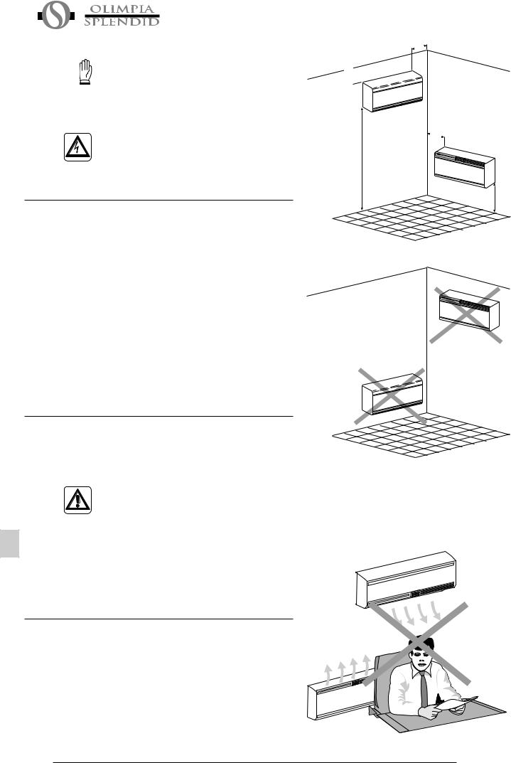
The position for installation of the inside unit, to obtain the bestperformanceandpreventbreakdownsorhazards,must have the following requisites:
-The bottom of the inside unit must be at least 2 meters off the floor and no more than 3 (fig. 1)
-The wall on which the inside unit is installed must be sturdy and able to withstand its weight.
-It must be possible to leave room around the unit for any maintenance operations that may be necessary.
-There should be no obstacles to the free circulation of air on theintakesideand,especially,ontheairoutletside;onthisside, in particular, there should be no obstacles closer than 2 m.
This could cause turbulence that would interfere with correct operation of the unit.
2.2.1 The air conditioner must be installed on a wall that Choice of best communicates with the outside.
position for installing the air conditioner
Caution: After determining the best place for installation as described above, check to make sure that the wall can be drilled in that point without interfering with other structures or installations (beams, piers, pipes, wires, etc.).
Check again to make sure there are no obstacles to air circulation through the holes to be drilled due to plants and their leaves, slats or panelling, blinds, gratings or grids too dense, etc.).
2.2.2 |
Before installing the air conditioner, it is essential to make |
Dimensions and |
an accurate calculation of the heat load in summer (and |
features of site |
cold load in winter for models with heating pump) at the |
where air |
site of installation. |
conditioner is |
The more accurate this calculation is made the better the |
installed |
air conditioner will be able to do its job. |
|
To make these calculations, refer directly to the regulations |
|
in effect (UNI ref. Law 10/91) or to the tables, both printed |
|
and computerized, based on those regulations. |
|
For particularly significant applications, we recommend |
|
contacting expert heating engineers. |
30
150 |
mm |
|
150 mm
OK
150 |
mm |
|
2 m (min) 3 m (max)
OK |
mm |
|
300 |
NO
NO
Fig.1
Fig. 2
UNICO-HE
As far as possible, in any case, it is important to try and reduce major thermal loads by the following means: Large glass panes exposed to sunlight should be provided with curtains on the inside or shades on the outside (Venetian blinds, verandas, refracting films, etc.)
The air-conditioned room should be closed as much of the time as possible.
Halogen spotlights or other electrical equipment with high power consumption should not be used in the room (toasters, steam irons, hot plates for cooking, etc.).
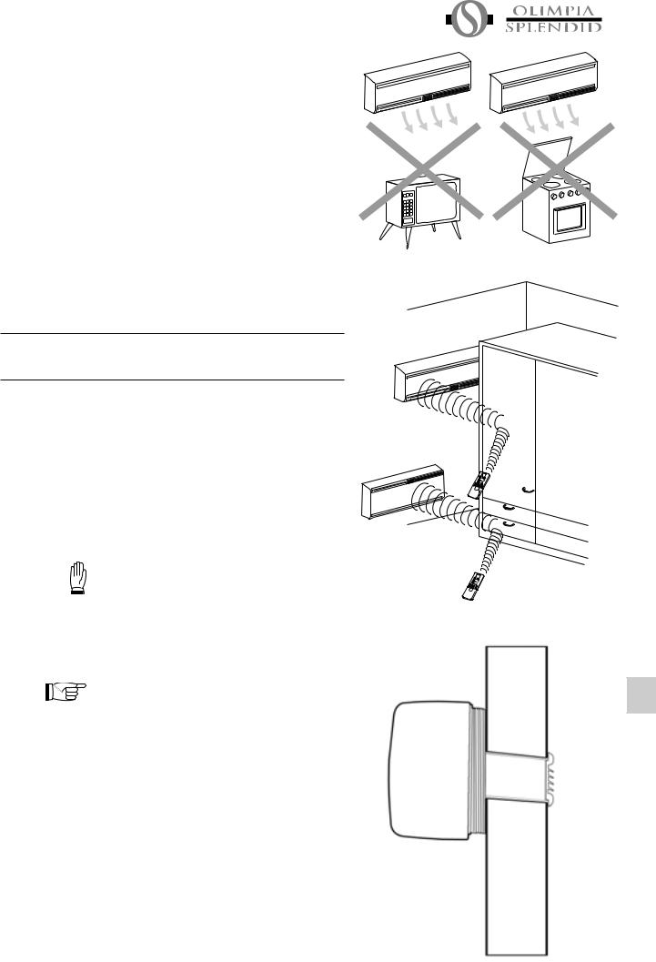
-It should not be installed in a position where the air flow can strike the people underneath directly (fig. 2).
-Itshouldnotbedirectlyoveranotherappliance(television set, radio, refrigerator, etc.), or over a source of heat (fig. 3).
-There should be no obstacles for reception of signals emitted by the remote control (fig. 4).
CHAP. 2.3 INSTALLATION OF THE UNIT
2.3.1 This operation should be carried out using the proper tools Drilling the wall to facilitate your work and prevent excess damage or
disturbance to your client.
The best tools for drilling large holes in walls are special drills called core borers with very high twisting torque and adjustable rotation speed depending on the diameter of the hole to be drilled.
To prevent the creation of large amounts of dust and rubble due to drilling, the core borer can be fitted with a vacuum system applied by means of suction cups to the drilling zone.
Our Service Department can give you all necessary information to enable you to find these devices.
To drill the holes, proceed as follows:
Fasten the drilling template to the wall leaving the necessary space from the ceiling, floor and side walls as shown on the template. Use adhesive tape to fasten it in place.
Use a small drill or punch to mark, with extreme care, the exact centre of each of the holes to be drilled.
Using a core boring head measuring at least 154 mm to drill the two holes for entry and exit of the air.
Note: The holes should have a slight outward inclination to prevent any backflow of water from the pipes (see fig.1).
Most of the removed material is expelled outwards, therefore make sure that it does not hit any person or object when it falls out.
In order to avoid as much as possible outer plaster breaking, it is necessary to proceed carefully with the last part of hole execution, decreasing pressure on core borers.
Fig. 3
Fig. 4
Fig. 5
UNICO-HE |
|
31 |
|
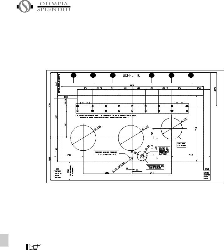
Next, drill the holes for anchoring the fastening brackets to the wall using as a first option the 4 holes on the ends of the bracket as shown on the drilling template (see fig. 6).
If the wall is not very solid, it is advisable to use some extra anchor bolts.
Fig. 6
As you can see, the bracket can be fastened in a number of different ways and positions. The air conditioner is heavier on the left-hand side, so it is best to make sure of a solid anchorage on that side. The anchor bolts provided require holes with a diameter of 10 mm. In any case, the wall should be inspected carefully to determine the best possible anchorage and type of bolts suitable for particular situations.
Warning: The manufacturer is not liable in case of underestimation of the structural consistency of the anchorage made at the time of installation. We therefore recommend that you perform this operation with the maximum care as, if not done properly, it can cause serious damage to persons and property.
When installing models equipped with heating pump, if no drainage well for condensate has been provided built into the wall (see paragraph 2.3.2), it will be necessary, to allow for drainage of the condensate, to drill a hole through the wall measuring 16 mm in diameter in the position shown on the template (see fig.6).
32 |
|
UNICO-HE |
|
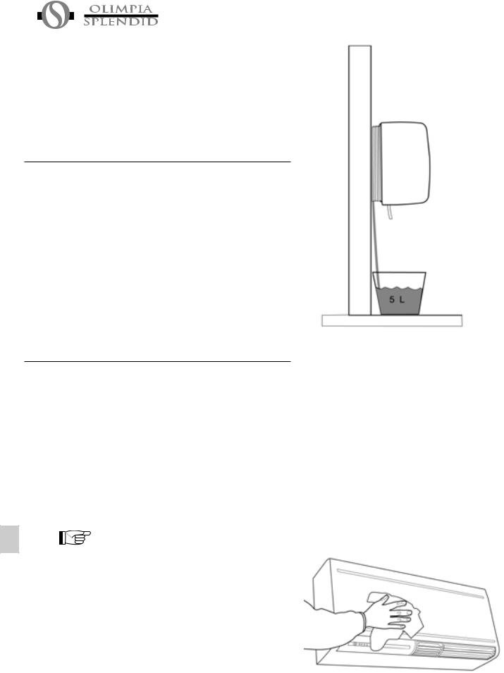
2.3.2 When the machine is heating, it produces condensate Provision for that has to be eliminated through a specific drain line, draining con- otherwise the machine will not work. Drainage occurs by densate for gravity. For this reason, it is essential for the drain line to machines with have a minimum inclination of at least 3% throughout its heat pump. length. The pipe can be rigid or not, with a minimum
internal diameter of 16 mm.
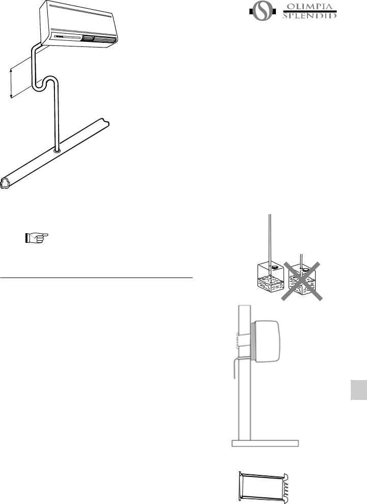
If the line drains into a sewer system, it should be provided with a trap ahead of the main outlet.
The trap should be at least 300 mm lower than the inlet opening on the air conditioner (fig. 7).
If the drainpipe drains into a vessel (tank or other container), this container should not be sealed and the drainpipe should not remain immersed in the water (see fig. 8).
The correct position for the pipe inlet on the machine is shown on the template for drilling and positioning the machine (see also fig. 6).
The air conditioner is equipped with a pipe with an external diameter of 14 mm for drainage of condensate.
This pipe protrudes from the machine for a length of about 400 mm.
The pipe should be fitted inside the one provided by you for a distance of at least 200 mm, without any sharp bends that could obstruct it.
When draining toward the outside, the pipe can be inserted through the wall (always making sure to give it a suitable inclination) (see fig. 5).
Caution: make sure, in this case, that the water expelled outward does not damage or disturb persons or property. During the winter this type of drainage may cause sheets of ice to form.
2.3.3 After drilling the holes, the plastic pipes supplied with the Installation of air air conditioner have to be fitted through them. The pipe pipes and with insulation on the inside has to be fitted in the right- external hand hole with the insulated part toward the inside as gratings indicated on the label applied to it. The length of the pipes should be 55 mm less than that of the wall. To cut the pipe, a normal handsaw can be used. After cutting the pipes, fit the ends into the two internal anchoring flanges
(fig. 10).
The tube diameter is nearly the same as those carried out using the 152/154 mm nominal diameter core drill. In order to introduce the tubes, they must therefore be forced slightly using, in the most difficult cases, a normal rubber hammer (fig. 10/1). Having the hole internal diameter extremely similar to the tube external diameter avoids dangerous slacks which may generate humidity infiltrations or air noises. Should the insertion prove to be too difficult, we suggest you drill using the core bit inside the hole so as to widen the internal diameter slightly.
Next, fit the pipes into the holes in the wall and fasten the flanges with 4 anchor bolts with diameter 6, taking care to keep the two fastening holes in a horizontal position.
Fig. 7
Fig. 8
Fig. 9
Fig. 10
UNICO-HE |
|
33 |
|
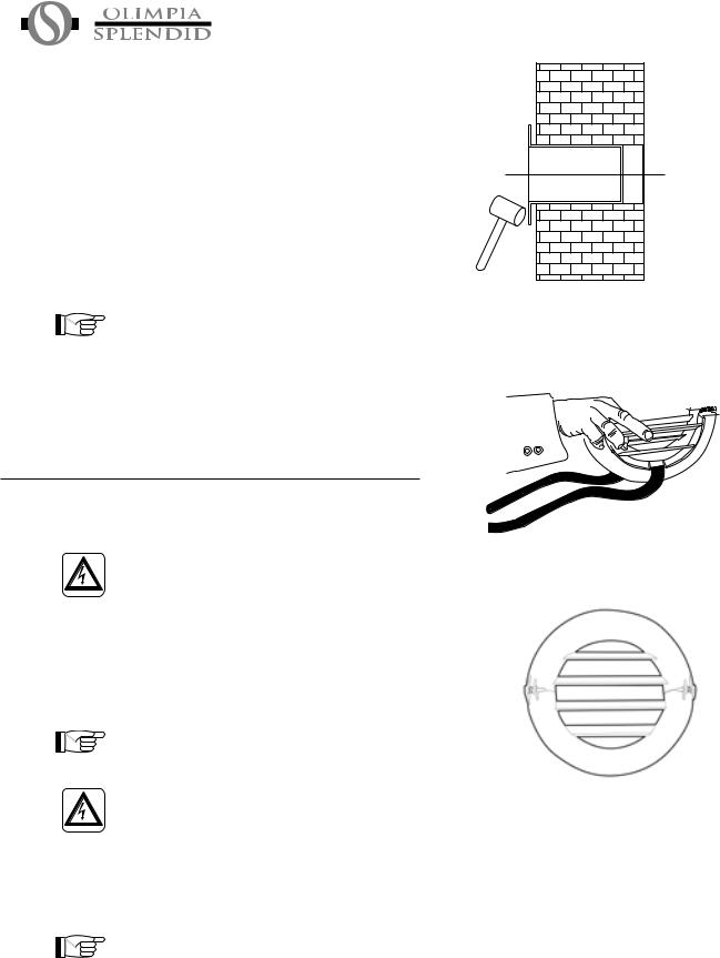
To position the external grating, proceed as follows:
-Grasp the two rubber belts attached to the grating in one hand.
-Fold the outer gratings in half by grasping them with your free hand along the fold line and inserting your fingers inside the fins (fig. 11).
Insert your arm inside the pipe until the grating protrudes all the way outside.
-Let the grating open, but keep your fingers inside the fins.
-Turn the grating so that the fins are perfectly horizontal with the inclination toward the outside (fig. 12).
-Pull the grating toward you.
-Tighten the rubber belts and fasten them to the two pins on the inner flange.
-Cut the excess part of the belt.
Warning: If the external grating is accessible, to prevent the hazards resulting from its possible removal (insertion of the hands into the pipes and touching moving or powered parts) it is absolutely essential to fasten it to the wall with 4 anchor bolts with a diameter of 6 mm.
2.3.4The air conditioner is equipped with a power supply cable
|
Power supply |
and plug. |
|
connection |
If it is installed near an outlet, you need only plug it in. |
|
|
In this case, it is important to make sure the outlet to |
|
|
which you are plugged in is effectively grounded and |
|
|
connected to the mains by wiring of adequate size |
|
|
(minimum 1.5 sq.mm. cross section). |
|
|
To make an electrical connection with the shielded cable |
|
|
(recommended for installations high on the wall) proceed |
|
|
as follows: |
|
|
Install a shunt box in the wall in the position shown on |
|
|
the installation template (fig. 6), where you should provide |
|
|
a power cable with a cross-section (two poles plus ground |
|
|
wire) of 2,5 sq.mm. |
|
|
Warning: The external power line should be provided |
|
|
with an overload circuit breaker with suitable capacity |
|
|
for the rating of the machine. |
|
|
Make all connections in compliance with the laws in |
|
|
effect. |
|
|
Close the shunt box with its cover after drilling a hole in it |
|
|
|
|
|
for passage of the cable. |
|
|
Alternatively, you can use a cable in the wall in the position |
|
|
|
|
|
shown on the template, for making the connection. In |
|
|
this case, remove the casing (as described in paragraph |
|
|
2.4.2) and connect the cable to the power terminal board. |
|
|
Caution: these operations should be performed with |
|
|
the machine already positioned on the bracket. Read |
|
|
the instructions carefully before completely the |
|
|
electric connection. |
Fig. 10/1
Fig. 11
Fig. 12
34 |
|
UNICO-HE |
|
2.3.5 After checking again that the fastening bracket is securely Fitting the unit fastened to the wall, and that any necessary preparations on bracket for electric connection and condensate drainage have been made, you can fasten the air conditioner to its supporting bracket. Lift it up holding the sides of the bottom
(see fig. 13).
To facilitate the operation of fastening it to the bracket, tilt it slightly toward you.
To make the electrical connection and fasten the drainpipe, place a wedge between the air conditioner and the wall (see fig. 14).
After these operations have been carried out, the air conditioner can be pushed firmly against the wall so that the bottom hook catches.
When you have finished, inspect carefully to make sure there are no fissures at the back of the air conditioner (the insulating gasket must fit firmly against the wall) particularly in the zone where air enters and leaves the machine.
Fig. 13
CHAP. 2.4 PREPARATIONFORASSEMBLY/INSTALLATION
WALL TOP PART
2.4.1 The air conditioner is assembled in the factory ready to Introduction be installed low on the wall.
The air outlet, in this case, is at the top of the air conditioner with the recycle grating and control panel.
In order to prepare the product for installation on the top part of the wall, follow the instructions below.
2.4.2 Removal of front
casing
Fig. 14
Note: if the air conditioner has not been installed on the wall yet, place it on its back. To not apply heavy pressure to the bottom of the device as this could dent or scratch the casing.
Use a small blade screwdriver to remove the horizontal strips on the casing, applying gentle leverage in the slits along the sides. (see fig. 15).
Take care not to scratch the strips or casing with the screwdriver point.
Unscrew the 8 self-threading screws that fasten the casing to the air conditioner.
Lift the casing off carefully, pulling it toward you by about 50 cm (see fig. 16).
Disconnect the fastener on the right that fastens the wires to the airflow deviation baffle adjustment motor (see fig. 17).
Now you can remove the casing completely.
Fig. 15
Fig. 17 |
Fig. 16 |
UNICO-HE |
|
35 |
|
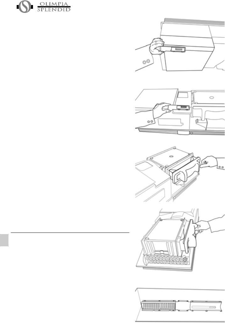
2.4.3 Unscrew the bracket supporting the small circuit board with Preparation of display leds and reinstall it on the bottom opposite, where
unit you will find two holes on the base (see fig. 18-19).
Make sure the connection plate is securely fastened on the inside of the air conditioner, and apply some insulating tape if necessary. Remove the styrofoam enclosure on the lower right-hand side under the air recycle fan and fit it against the opening above the fan (see fig. 20-21).
Remove the air outlet grating by removing the fastening screws. Remove the control panel (see fig. 22).
When performing this operation place the casing on a secure surface so as not to scratch or dent it. Remove the plastic plate with the logo and transparent screen for display of the leds from the control panel by pressing on the hooks at the rear. Turn it over (rotate by 180°) and reinstall it on the panel.
Reassemble the parts in the opposite position from the original installation, reversing the air outlet grating with the control panel grating.
Turn the casing over so that the air outlet grating is on the lower right-hand side of the device.
Connect the plug on the step-step motor of the grating. Fit the casing back on the air conditioner carefully, taking care to hold the wires for the step-step motor to one side so that they do not interfere with the inner part of the air outlet grating.
Check that all the coupling references of the casing with the rear frame are fully inserted so that the casing is fitted smoothly and evenly all around.
Fasten the casing with its eight screws and replace the strips in their slots.
After completing installation, the electronic parts of the air conditioner have to be configured so as to take into account the stratification of heat in the room. This procedure is outlined in paragraph 2.5 (Operating tests and diagnosis of possible malfunctions).
CHAP. 2.5 WORKING TESTS AND IDENTIFICATION OF POSSIBLE MALFUNCTIONS
The program introduced in the microprocessor of this device makes it possible to run a brief self-test to ensure that the machine functions normally by starting each of its internal components.
To run the self-test, proceed as follows:
-Power the air conditioner and make sure it is on stand-by.
-Use a sharp object to press the microkey located under the hole on the left of the control panel for at least 10 sec.
-At the beginning and end of the self-test procedure the status of configuration of the machine will be displayed for a few seconds as follows:
Fig. 18
Fig. 19
Fig. 20
Fig. 21
Fig. 22
36 |
|
UNICO-HE |
|

red led (filter): |
off = UNICO |
|
|
|
on = UNICO HP (with heat |
|
|
|
pump) |
|
|
green led (compr.): |
off = with correction of room tem- |
green orange green |
red |
|
perature |
|
|
|
on = without correction of room |
|
|
|
temperature |
|
|
orange led (timer): |
off = without correction of room |
|
|
|
temperature |
|
|
|
on = with correction of room tem- |
|
|
|
|
|
|
|
perature |
|
|
green led (power): |
off = stand-by in case of black- |
|
|
|
|
||
|
out |
|
|
|
on = restart in case of black-out |
|
|
-Check after a few seconds to see whether the equipment heats normally (if equipped with heat pump function) for about 2 minutes and then, after a few seconds, that it cools for another 2 minutes.
Before concluding the self-test, the electronic part tests the temperature probes to make sure they are operating normally. If any of these should not be working, the corresponding signal led remains lit for 20 sec. (see table on next page).
Should there be a jam in the air-conditioning system with alarm signals according to the table here following, please be ready to refer to the Service Centre which leds are blinking in order to simplify their intervention.
Starting from the left:
CODE |
DESCRIPTION |
green LED |
orange LED |
green LED |
red LED |
|
|
ALARM |
POWER |
TIMER |
COMPR. |
FILTER |
|
|
|
1-FS |
dirty filter |
|
|
|
O |
|
|
|
|
|
|
|
|
|
|
2-HTI |
internal battery overheat |
|
|
O |
|
|
|
3-HTE |
external battery overheat |
|
|
O |
O |
|
|
4-LT |
internal battery low temp. |
|
O |
|
|
|
|
5 |
pump working continuously |
|
O |
|
O |
|
|
6-CF/RL |
batt. temp. not reached |
|
O |
O |
|
|
|
7-OF |
water level |
|
O |
O |
O |
|
|
8-CKS |
eeprom parameters not valid |
O |
|
|
|
|
|
9 |
- |
O |
|
|
O |
|
|
10-TSF |
short on room sensor |
O |
|
O |
|
|
|
11-TSF |
room sensor disconnected |
O |
|
O |
O |
|
|
12-TSF |
short on evaporator sensor |
O |
O |
|
|
|
|
13-TSF |
evap. sensor disconnected |
O |
O |
|
O |
|
|
14-TSF |
short on condenser sensor |
O |
O |
O |
|
|
|
|
|
|
|||||
15-TSF |
condenser sensor |
O |
O |
O |
O |
|
|
|
|
|
|
|
|
|
|
The end of the self-test will be signalled by all the leds lighting up at once and blinking ten times, as well as by an acoustic signal.
At this time, you can adjust the temperature reading on the room temperature sensor. This correction is important if the air conditioner is installed high on the wall in a room where the warm air tends to stratify upward (as in rooms with high ceilings or other sources of heat besides the air conditioner). The sensor will read a temperature 3°C lower than the effective one, in this case, to compensate for the difference between the lower inhabited part of the room and the temperature at the height of the sensor.
To enter or remove this correction proceed as follows: 1 Check the status of the machine as described previously, and if no correction has been made, press the button on the console while the acoustic signal is
on at the end of the self-test.
2To remove the correction, press the button while the acoustic signal is on at the end of the self-test.
UNICO-HE |
|
37 |
|
The machine is set in the factory without correction of the temperature.
In addition to the self-test (that can be made under any conditions of room temperature) we recommend that you also test the product in the various operating modes accessible to the user (see the user manual). One important test you should make concerns regular evacuation of condensation water on the models with heat pump. To check this, keep the machine running for at least 4-5 hours in the heating mode. If the water does not drain, there should be an “overflow” alarm.
2.5.1 If there should be a malfunction in the condensation water Evacuation of drain system, the air conditioner stops working and condensation signals, with flashing orange, green and red lights (the
water in case of second and third leds from the left), the alarm status. emergency To enable the air conditioner to work temporarily until the
service personnel arrives, you can drain the water out by following these simple instructions:
-Grasp the rubber cap on the bottom centre of the air conditioner behind the edge of the frame facing the wall between your thumb and forefinger.
-Pull the rubber tube closed by the cap out by a few centimetres.
-Remove the cap after placing a bucket or other container underneath it (at least five litter capacity) to collect the water (see fig. 23).
-After eliminating the malfunction the service personnel will take care of closing the evacuation tube.
Fig. 23
CHAP. 2.6 PERIODICAL MAINTENANCE
Air conditioners of this type do not require any particular routine maintenance except:
-Cleaning or washing the room air filter when the red led lights up (see user manual).
-Cleaning of “external air” battery, to be done as needed, depending on the amount of dirt in the external air, once or twice a year. To do this, you must, of course, open the air conditioner by removing its casing and the noise insulation on the inside.
-Cleaning can be done using a vacuum cleaner or soft brush, taking particular care not to damage the aluminium heat exchanger baffles. It may be necessary to use water and detergents to remove heavily encrusted dirt.
Note: after cleaning the battery replace the noise insulation carefully matching the edges and gaskets with their reference markings.
Before you leave the site of installation you should gather up all packing material and use a damp cloth to remove any traces of dust that may have deposited on the machine during assembly (fig. 24).
These operations, though certainly not essential, have a beneficial effect as they enhance the professional image of the installer in the eyes of the client.
To prevent unnecessary calls by the user, before you leave the site of installation it is also a good idea to:
-Explain the contents of the Instruction Manual to the user.
-Show him how to clean the filter.
-Explain when and how he should contact the Service Department
Fig. 24
38 |
|
UNICO-HE |
|
CHAP. 3 USE AND MAINTENANCE (for the user)
CHAP. 3.1 Important Recommendations
Installation and connection of the air conditioner should be carried out by specialized personnel in possession of the qualifications specified in Law 46/90.
The instructions for installation are provided in the specific manual.
No structural object (furniture, curtains, plants, leaves, blinds, etc.) should ever obstruct the normal flow of air from either the internal or external gratings.
Never lean or, worse yet, sit on the casing of the air conditioner as this could cause serious damage to the external parts.
Do not turn the horizontal airflow baffles by hand. Always use the remote control to adjust baffle position.
If the unit leaks water, switch it off immediately and disconnect it from the power mains. Call the nearest service centre.
When the air conditioner is heating, it has to periodically eliminate any ice that could form on the external battery. While it is doing this, the machine keeps running but does not heat the room. This lasts for a brief period of time, from 3 to a maximum of 10 minutes.
The air conditioner must not be installed in rooms where explosive gasses develop or where there are conditions of heat and humidity beyond the maximum limits indicated in the installation manual.
Clean the air filter periodically, as described in the specific paragraph.
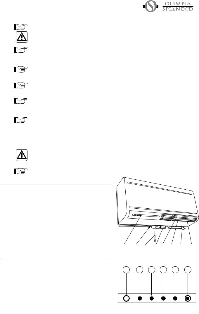
3.2 |
NAMES OF PARTS |
|
|
|
|
3.2.1 |
1) |
Air outlet grating.. |
List of Units |
2) |
Cursors for lateral adjustment of airflow. |
|
3) |
Motor-operated air baffles for upward airflow |
|
4) |
Alarm display console. |
|
5) |
Air intake grating. |
|
6) |
Grips for removal of air filter. |
|
7) |
Rubber hose with cap on end for evacuation of |
|
8) |
condensation water in case of emergency. |
|
Power cable |
|
3.2.2 |
1) |
Transparent zone of receipt of remote control signal. |
Description of |
2) |
Green led indicating machine is running (When the |
signal console |
3) |
machine is on stand-by this light is off). |
|
Orange led indicates on/off programming is in use. |
|
|
4) |
Green led indicates cooling compressor is on. |
|
5) |
Red led indicates air filter clogged. |
|
6) |
Service microkey (RESET) |
UNICO-HE
4 |
7 |
8 |
5 |
3 |
2 |
6 |
1 |
|
|
Fig. 25
1 |
2 |
3 |
4 |
5 |
6 |
Fig. 26
39
 Loading...