


 Loading...
USB2000
Fiber Optic Spectrometer
Installation and Operation Manual
Document Number 170-00000-000-02-1005
Offices: |
Ocean Optics, Inc. |
|
|
830 Douglas Ave., Dunedin, FL., USA 34698 |
|
|
Phone |
727.733.2447 |
|
Fax |
727.733.3962 |
|
8 a.m.– 8 p.m. (Mon-Thu), 8 a.m.– 6 p.m. (Fri) EST |
|
Ocean Optics B.V. (Europe)
Geograaf 24, 6921 EW DUIVEN, The Netherlands
|
Phone 31-(0)26-3190500 |
|
|
|
Fax |
31-(0)26-3190505 |
|
|
|
|
|
E-mail: |
Info@OceanOptics.com |
(General sales inquiries) |
|
|
Info@OceanOpticsBV.com |
(European sales inquiries) |
|
|
Orders@OceanOptics.com |
(Questions about orders) |
|
|
TechSupport@OceanOptics.com |
(Technical support) |
|

Copyright © 2001-2005 Ocean Optics, Inc.
All rights reserved. No part of this publication may be reproduced, stored in a retrieval system, or transmitted, by any means, electronic, mechanical, photocopying, recording, or otherwise, without written permission from Ocean Optics, Inc.
This manual is sold as part of an order and subject to the condition that it shall not, by way of trade or otherwise, be lent, re-sold, hired out or otherwise circulated without the prior consent of Ocean Optics, Inc. in any form of binding or cover other than that in which it is published.
Trademarks
Microsoft, Windows, Windows 95, Windows 98, Windows ME, Windows NT, Windows 2000, Windows XP and Excel are either registered trademarks or trademarks of Microsoft Corporation.
Limit of Liability
Every effort has been made to make this manual as complete and as accurate as possible, but no warranty or fitness is implied. The information provided is on an “as is” basis. Ocean Optics, Inc. shall have neither liability nor responsibility to any person or entity with respect to any loss or damages arising from the information contained in this manual.

Table of Contents
1 |
USB2000 Introduction ..................................................................................................................... |
1 |
|
Product Overview .................................................................................................................................................. |
1 |
|
System Requirements ................................................................................................................................................................................... |
1 |
|
EEPROM Utilization ...................................................................................................................................................................................... |
1 |
|
About OOIBase32 ......................................................................................................................................................................................... |
2 |
|
Sampling System Overview .......................................................................................................................................................................... |
2 |
|
Modular Sampling Accessories ..................................................................................................................................................................... |
2 |
|
Interface Options ................................................................................................................................................... |
3 |
|
Shipment Components .......................................................................................................................................... |
3 |
|
Packing List ................................................................................................................................................................................................... |
3 |
|
Wavelength Calibration Data Sheet .............................................................................................................................................................. |
3 |
|
Software and Technical Resources CD ........................................................................................................................................................ |
4 |
|
Other Documentation .................................................................................................................................................................................... |
4 |
|
Modification and Repair Policy ...................................................................................................................................................................... |
4 |
2 |
USB2000 Specifications.................................................................................................................. |
5 |
|
How the USB2000 Works ...................................................................................................................................... |
5 |
|
USB2000 Component Table ......................................................................................................................................................................... |
6 |
|
USB2000 Specifications ........................................................................................................................................ |
7 |
|
CCD Detector Specifications......................................................................................................................................................................... |
7 |
|
USB2000 Spectrometer Specifications ......................................................................................................................................................... |
7 |
|
System Compatibility..................................................................................................................................................................................... |
8 |
|
10-pin Accessory Connector Pinout .............................................................................................................................................................. |
8 |
|
10-Pin Accessory Connector Pinout Diagram ............................................................................................................................................... |
9 |
|
10-Pin Accessory Connector – Pin Definitions.............................................................................................................................................. |
9 |
|
10-Pin J2 Accessory Connector – Part Number and Compatibility............................................................................................................... |
9 |
3 |
Installing the USB2000 .................................................................................................................. |
10 |
|
USB2000 Installation ........................................................................................................................................... |
10 |
|
Configuring the USB2000 in OOIBase32 .................................................................................................................................................... |
11 |
|
Connect Spectroscopic Accessories ........................................................................................................................................................... |
13 |
|
External Triggering Options................................................................................................................................. |
13 |
4 |
Troubleshooting ............................................................................................................................ |
14 |
|
USB2000 Connected to PC Prior to OOIBase32 Installation .............................................................................. |
14 |
|
Remove the Unknown Device from Windows Device Manager.................................................................................................................. |
14 |
|
Windows 98:................................................................................................................................................................................................ |
15 |
|
Windows 2000/XP: ...................................................................................................................................................................................... |
16 |
|
Troubleshooting the Serial Port Configuration..................................................................................................... |
17 |
|
Older Version of OOIBase32 Installed ................................................................................................................ |
17 |
5 |
Sample Experiments ..................................................................................................................... |
18 |
|
Preparing for Experiments................................................................................................................................... |
18 |

Absorbance Experiments..................................................................................................................................... |
20 |
Transmission Experiments .................................................................................................................................. |
22 |
Reflection Experiments........................................................................................................................................ |
24 |
Relative Irradiance Experiments.......................................................................................................................... |
26 |
Time Acquisition Experiments ............................................................................................................................. |
28 |
Appendix A: Calibrating the Wavelength of the USB2000 ............................................................ |
31 |
About Wavelength Calibration ............................................................................................................................. |
31 |
Calibrating the Spectrometer............................................................................................................................... |
31 |
Preparing for Calibration ............................................................................................................................................................................. |
31 |
Calibrating the Wavelength of the Spectrometer......................................................................................................................................... |
32 |
Saving the New Calibration Coefficients: USB Mode.................................................................................................................................. |
34 |
Saving the New Calibration Coefficients: Serial Mode................................................................................................................................ |
35 |
Appendix B: USB2000-FLG Spectrometer......................................................................................... |
36 |
About the USB2000-FLG..................................................................................................................................... |
36 |
Using the USB2000-FLG..................................................................................................................................... |
36 |
Index ...................................................................................................................................................... |
38 |
USB2000 Introduction
1 USB2000 Introduction
The following chapter contains introductory information about the USB2000 Spectrometer, shipment information, and spectrometer connectivity.
Product Overview
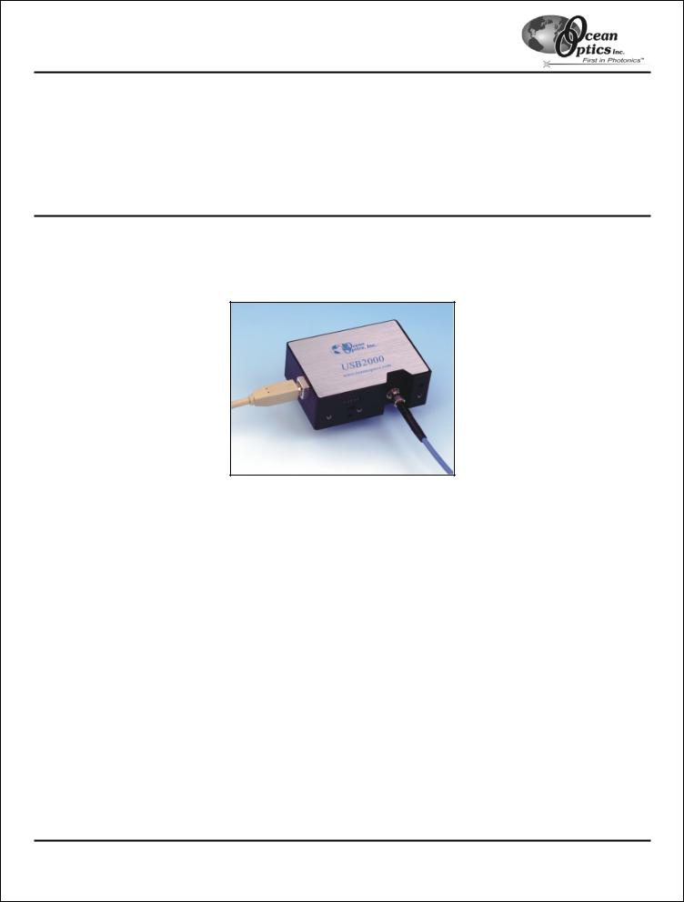
The USB2000 Spectrometer connects to a notebook or desktop PC via USB port or serial port. When connected to the USB port of a PC, the USB2000 draws power from the host PC, eliminating the need for an external power supply.
Figure 1-1: Ocean Optics USB2000 Fiber Optic Spectrometer
System Requirements
You can use the USB2000’s USB connectivity with any PC that meets the following requirements:
•Windows 98/Me/2000/XP operating system (or Windows CE 2.11 or later for palm-sized PCs)
•Ocean Optics OOIBase32 software application installed and configured for use with the USB2000 (OOIPS2000 software if using a palm-sized PC). Consult the “Configuring the USB2000 in OOIBase32” section of Chapter 3: Installing the USB2000 for specific configuration instructions.
Alternately, the USB2000 has a serial port for connecting to PCs, PLCs, and other devices that support the RS232 communication protocol. However, this connection method requires an external power supply to power the USB2000.
EEPROM Utilization
An EEPROM memory chip in each USB2000 contains wavelength calibration coefficients, linearity coefficients, and a serial number unique to each individual spectrometer. The OOIBase32 software application reads these values directly from the spectrometer, enabling the ability to “hot-swap” spectrometers between PCs without entering the spectrometer coefficients manually on each PC.
USB2000 Operating Instructions |
1 |

USB2000 Introduction
About OOIBase32
OOIBase32 is the latest generation of operating software for all Ocean Optics spectrometers and is available free to all customers. OOIBase32 is a user-customizable, advanced acquisition and display program that provides a real-time interface to a variety of signal-processing functions. With OOIBase32, you have the ability to perform spectroscopic measurements (such as absorbance, reflectance, and emission), control all system parameters, collect and display data in real time, and perform reference monitoring and time acquisition experiments.
Note: When using a palm-sized PC, you will use the OOIPS2000 software instead of OOIBase32. The functionality of OOIPS2000 is similar to OOIBase32, but it is specifically for the palm-sized PC.
Sampling System Overview
Ocean Optics fiber optic spectrometer systems consist of low-cost, modular data acquisition components. A typical USB2000-based sampling system contains four core elements:
•USB2000 Spectrometer
•OOIBase32 operating software
•Light source
•Sampling optics (varying, depending on application requirements)
How Sampling Works
The following list explains the function of Ocean Optics sampling components in the sampling process:
1.The user stores reference and dark measurements to correct for instrument response variables.
2.The light from the light source transmits through an optical fiber to the sample.
3.The light interacts with the sample.
4.Another optical fiber collects and transmits the result of the interaction to the spectrometer.
5.The spectrometer measures the amount of light and transforms the data collected by the spectrometer into digital information.
6.The spectrometer passes the sample information to OOIBase32.
7.OOIBase32 compares the sample to the reference measurement and displays processed spectral information.
Modular Sampling Accessories
Ocean Optics offers a complete line of spectroscopic accessories for use with the USB2000. Most of our spectroscopic accessories have SMA connectors for application flexibility. Accordingly, changing the sampling system components is as easy as unscrewing a connector and replacing an accessory.
USB2000 Operating Instructions |
2 |

USB2000 Introduction
Interface Options
The USB2000 has both USB and serial port connectors, enabling you to connect the spectrometer to a desktop or notebook PC via a USB port or to a desktop, notebook, or to a palm-sized PC via a serial port.
Computer |
Operating System |
Part Needed |
Description of Part |
|
Interface |
Requirements |
|||
|
|
|||
Desktop or |
Windows 98/Me/ |
USB-CBL-1 |
Cable that connects from USB port on USB2000 to USB port on |
|
Notebook PC |
||||
2000/XP |
(included) |
desktop or notebook PC |
||
via USB Port |
||||
|
|
|
||
Desktop or |
Any 32-bit |
USB-ADP-PC |
Adapter block that enables connection from serial port on |
|
Notebook PC |
Windows operating |
USB2000 to serial port on desktop or notebook PC; comes with |
||
(not included) |
||||
via Serial Port |
system |
5 VDC power supply (required when connecting to serial port) |
||
|
||||
|
|
|
Adapter block that enables connection (with standard 9-pin |
|
Palm-sized PC |
Windows CE 2.11 |
USB-ADP-H |
serial cable) from serial port on USB2000 to serial port on palm- |
|
via Serial Port |
or higher |
(not included) |
sized PC; comes with 5 VDC power supply (required when |
|
|
|
|
connecting to serial port) |
Shipment Components
The following information and documentation ships with the USB2000 Spectrometer:
Packing List
The packing list is inside a plastic bag attached to the outside of the shipment box (the invoice arrives separately). The packing slip lists all items in the order, including customized components in the spectrometer (such as the grating, detector collection lens, and slit). The packing list also includes the shipping and billing addresses, as well as any items on back order.
Wavelength Calibration Data Sheet
Each spectrometer is shipped with a Wavelength Calibration Data Sheet that contains information unique to your spectrometer. OOIBase32 Operating Software reads this calibration data from your spectrometer when it interfaces to a PC via the USB port. Any other interface requires that you manually enter the calibration data in OOIBase32 (select Spectrometer | Configure | Wavelength Calibration tab). See the OOIBase32 documentation for more information (refer to Product Overview for instructions on accessing OOIBase32 documentation).
Note: Please save the Wavelength Calibration Data Sheet for future reference.
USB2000 Operating Instructions |
3 |

USB2000 Introduction
Software and Technical Resources CD
Each order ships with the Ocean Optics Software and Technical Resources CD. This disc contains software, operating instructions, and product information for all Ocean Optics software, spectrometers, and spectroscopic accessories. You need Adobe Acrobat Reader version 6.0 or higher to view these files. Ocean Optics includes Adobe Acrobat Reader on the Software and Technical Resources CD.
With the exception of OOIBase32 Spectrometer Operating Software, all Ocean Optics software requires a password during the installation process. You can locate passwords for the other software applications on the back of the Software and Technical Resources CD package.
Other Documentation
You can find detailed instructions for the OOIBase32 Spectrometer Operating Software at http://www.oceanoptics.com/technical/operatinginstructions.asp.
Note: You can find instructions for the OOIPS2000 Operating Software for the handheld PC at the following location: http://www.oceanoptics.com/products/ooips2000.asp.
To find operating instructions on some of Ocean Optics’ most popular spectroscopic accessories (including light sources, sampling chambers, sampling optics, and probes), consult the operating instructions for Ocean Optics products from the Software and Technical Resources CD that ships with the product, or visit our website at http://www.oceanoptics.com/technical/operatinginstructions.asp.
Modification and Repair Policy
In the event that you need to return an item for modification or service, you must obtain a Return Merchandise Authorization (RMA) number prior to shipping the item back to Ocean Optics. Contact an Ocean Optics Applications Scientist for specific instructions on returning an item.
USB2000 Operating Instructions |
4 |
USB2000 Specifications
2 USB2000 Specifications
This chapter contains information on spectrometer operation, specifications, and system compatibility. It also includes accessory connector pinout diagrams and pin-specific information.
How the USB2000 Works
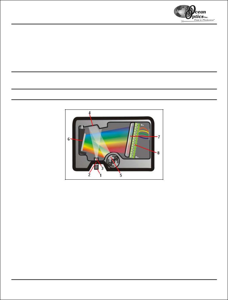
The following diagram illustrates the movement of light through the optical bench of the USB2000 Spectrometer. You can customize the items marked with an asterisk (*) when ordering the USB2000.
Note: The optical bench has no moving parts that can wear or break. Ocean Optics secures all components in place permanently at the time of manufacture.
Figure 2-1: USB2000 Spectrometer with Components
The USB Component Table on the following page explains the function of each numbered component in the USB2000 Spectrometer diagram (Figure 2-1).
USB2000 Operating Instructions |
5 |

USB2000 Specifications
USB2000 Component Table
Ocean Optics permanently secures all components in the USB2000 at the time of manufacture. Only Ocean Optics Technicians can replace interchangeable components, where noted.
Item Name
1SMA Connector
2Slit*
3Filter*
4Collimating Mirror
5Grating*
6Focusing Mirror
7L2 Detector Collection Lens*
8CCD Detector (UV or VIS)
Description
The SMA Connector secures the input fiber to the spectrometer. Light from the input fiber enters the optical bench through this connector.
The Slit is a dark piece of material containing a rectangular aperture, which is mounted directly behind the SMA Connector. The size of the aperture regulates the amount of light that enters the optical bench and controls spectral resolution.
You can also use the USB2000 without a Slit. In this configuration, the diameter of the fiber connected to the USB2000 determines the size of the entrance aperture.
Only Ocean Optics technicians can change the Slit.
The Filter is a device that restricts optical radiation to pre-determined wavelength regions. Light passes through the Filter before entering the optical bench. Both bandpass and longpass filters are available to restrict radiation to certain wavelength regions.
Only Ocean Optics technicians can change the Filter.
The Collimating Mirror focuses light entering the optical bench towards the Grating of the spectrometer.
Light enters the spectrometer, passes through the SMA Connector, Slit, and Filter, and then reflects off the Collimating Mirror onto the Grating.
The Grating diffracts light from the Collimating Mirror and directs the diffracted light onto the Focusing Mirror. Gratings are available in different groove densities, allowing you to specify wavelength coverage and resolution in the spectrometer.
Only Ocean Optics technicians can change the Grating.
The Focusing Mirror receives light reflected from the Grating and focuses the light onto the CCD Detector or L2 Detector Collection Lens (depending on the spectrometer configuration).
The L2 Detector Collection Lens (optional) attaches to the CCD Detector. It focuses light from a tall slit onto the shorter CCD Detector elements.
The L2 Detector Collection Lens should be used with large diameter slits or in applications with low light levels. It also improves efficiency by reducing the effects of stray light.
Only Ocean Optics technicians can add or remove the L2 Detection Collection Lens.
The CCD Detector collects the light received from the Focusing Mirror or L2 Detector Collection Lens and converts the optical signal to a digital signal.
Each pixel on the CCD Detector responds to the wavelength of light that strikes it, creating a digital response. The spectrometer then transmits the digital signal to the OOIBase32 application.
USB2000 Operating Instructions |
6 |

USB2000 Specifications
USB2000 Specifications
The following sections provide specification information for the CCD Detector in the USB2000, as well as the USB2000 Spectrometer itself.
CCD Detector Specifications
Detector: |
Sony ILX511 linear silicon CCD array |
Number of elements: |
2048 pixels |
Pixel size: |
14 µm x 200 µm |
Pixel well depth: |
62,500 electrons |
Signal-to-noise ratio: |
250:1 (at full signal) |
A/D resolution: |
12 bit |
Dark noise: |
2.5 RMS counts |
Corrected linearity: |
>99.8% |
USB2000 Spectrometer Specifications
|
Dimensions: |
89.1 mm x 63.3 mm x 34.4 mm |
|
Weight: |
190 g (without cable) |
|
Power consumption: |
90 mA @ 5 VDC |
|
Detector range: |
200-1100 nm |
|
Detector: |
2048-element linear silicon CCD array |
|
Gratings: |
14 gratings; UV through Shortwave NIR |
|
Entrance aperture: |
5, 10, 25, 50, 100 or 200 mm wide slits or fiber (no slit) |
|
Order-sorting filters: |
Installed longpass and bandpass filters |
|
Focal length: |
f/4, 42 mm (input); 68 mm (output) |
|
Optical resolution: |
~0.3-10.0 nm FWHM (depending on grating and size of entrance aperture) |
|
Dynamic range: |
2 x 10⁸ (system); 2000:1 for a single scan |
|
Stray light: |
<0.05% at 600 nm; <0.10% at 435 nm; <0.10% at 250 nm |
|
Sensitivity (estimate): |
400 nm – 90 photons/count; 600 nm – 41 photons/count; |
|
800 nm – 203 photons/count |
|
|
|
|
|
Fiber optic connector: |
SMA 905 to single-strand optical fiber (0.22 NA) |
|
Data transfer rate: |
Full scans into memory every 13 milliseconds |
|
Integration time: |
3 milliseconds to 65 seconds |
|
Fiber optic connector: |
SMA 905 to single-strand optical fiber (0.22 NA) |
|
|
Windows 98/Me/2000/XP when using the USB interface on a desktop or notebook |
|
|
PCs |
|
Operating systems: |
Any 32-bit Windows operating system when using the serial port on desktop or |
|
|
notebook PCs |
|
|
Windows CE 2.11 and above when using the serial port on palm-sized PCs |
|
|
|
|
USB2000 Operating Instructions |
7 |

USB2000 Specifications
System Compatibility
The following sections provide information on hardware and software requirements for the USB2000:
Compatibility for Desktop or Notebook PCs
To use the USB2000, you must have a PC that meets the following minimum requirements:
•IBM-compatible PC with Pentium (or higher) processor
•32 MB RAM
•OOIBase32 Spectrometer Operating Software
•Windows 98/Me/2000/XP operating system (when connecting the USB2000 to a PC via USB port) or
Any 32-bit version of Windows (when connecting the USB2000 to a PC via serial port)
Compatibility for Palm-sized PCs
In order to use the USB2000 with your palm-sized PC, the computer must meet the following requirements:
•Palm-sized PC running Windows CE 2.11 or higher
•32 MB
•OOIPS2000 Spectrometer Operating Software
•Serial port connectivity
10-pin Accessory Connector Pinout
The USB2000 features a 10-pin Accessory Connector, located on the side of the unit as follows:
10-pin Connector
Figure 2-2: Location of USB2000 10-pin Connector
USB2000 Operating Instructions |
8 |
Loading...