


 Loading...
Operating Manual
and User’s Guide
S2000 Miniature Fiber Optic
Spectrometers and Accessories
Offices: |
East Coast |
|
380 Main Street, Dunedin, Fla., USA |
|
727.733.2447 • 727.733.3962 Fax |
|
8:30 a.m.-6 p.m. EST |
|
West Coast |
|
5190 Golden Foothill Parkway, El Dorado Hills, Calif., USA |
|
916.939-4300 • 916.939.4307 Fax |
|
Noon-9 p.m. EST |
|
Ocean Optics B.V. (Europe) |
|
Nieuwgraaf 108 G, 6921 RK DUIVEN, The Netherlands |
|
31-(0)26-3190500 • 31-(0)26-3190505 Fax |
E-mail: |
Info@OceanOptics.com (general sales inquiries) |
|
Info@OceanOpticsBV.com (for sales questions in Europe) |
|
Orders@OceanOptics.com (for questions about orders) |
|
TechSupport@OceanOptics.com (for technical support) |
|
For all your photonice needs, visit: |
|
OceanOptics.com |
122800
Copyright © 2000 Ocean Optics, Inc.
All rights reserved. No part of this publication may be reproduced or transmitted in any form or by any means, electronic or mechanical, including photocopy, recording, or stored in a retrieval system, without written permission from Ocean Optics, Inc.
This manual may be saved on the customer's PC and may be printed in sufficient quantities for those using and operating Ocean Optics products only and not for resale.
This manual is sold as part of an order and subject to the condition that it shall not, by way of trade or otherwise, be lent, re-sold, hired out or otherwise circulated without the prior consent of Ocean Optics, Inc. in any form of binding or cover other than that in which it is published.
Trademarks
Microsoft, Excel, Windows, Windows 95, Windows 98, and Windows NT are either registered trademarks or trademarks of Microsoft Corporation.
DAQCard-700 and LabVIEW are registered trademarks of National Instruments. GRAMS32 is a registered trademarks of Galactic Industries Corportation.
Spectralon is a registered trademark of Labsphere, Inc.
Limit of Liability
Every effort has been made to make this manual as complete and as accurate as possible, but no warranty or fitness is implied. The information provided is on an "as is" basis. Ocean Optics, Inc. shall have neither liability nor responsibility to any person or entity with respect to any loss or damages arising from the information contained in this manual.

Table of Contents
Introduction .......................................................................................................................... |
5 |
Quick Start............................................................................................................................. |
9 |
S2000 Miniature Fiber Optic Spectrometer ...................................................... |
11 |
S2000 Specifications............................................................................................................ |
12 |
S2000 Board Layout ............................................................................................................ |
13 |
A/D Converters.................................................................................................................. |
14 |
ADC500 ISA-bus A/D Converter.......................................................................................... |
15 |
ADC1000 ISA-bus A/D Converter (and PC2000) ................................................................ |
19 |
SAD500 Serial Port Interface............................................................................................... |
23 |
DAQ-700 PCMCIA A/D Converter ....................................................................................... |
26 |
OOIBase32 Operating Software.............................................................................. |
31 |
Light Sources .................................................................................................................... |
33 |
MINI-D2T Miniature Deuterium Tungsten Light Source....................................................... |
34 |
D-1000 Deuterium Light Source .......................................................................................... |
36 |
DT-1000 Deuterium Tungsten Halogen Light Source.......................................................... |
38 |
LS-1 Tungsten Halogen Light Source.................................................................................. |
41 |
PX-2 Pulsed Xenon Lamp.................................................................................................... |
43 |
LS-450 Blue LED Pulsed Light Source................................................................................ |
45 |
R-LS-450 Rack-mount Blue LED Pulsed Light Source ....................................................... |
46 |
HG-1 Mercury Argon Calibration Source ............................................................................. |
49 |
LS-1-CAL Calibrated Light Source....................................................................................... |
52 |
Sampling Chambers ...................................................................................................... |
54 |
CUV-UV, CUV-VIS Cuvette Holders .................................................................................... |
55 |
CUV-UV-10, CUV-VIS-10 Cuvette Holders ......................................................................... |
57 |
CUV-ALL 4-way Cuvette Holder .......................................................................................... |
58 |
CUV-FL-DA Direct Attach Cuvette Holder ........................................................................... |
60 |
ISS Integrated Sampling System ......................................................................................... |
62 |
ISS-2 Integrated Sampling System...................................................................................... |
64 |
ISS-UV-VIS Integrated Sampling System............................................................................ |
66 |
FHS-UV, FHS-VIS In-line Filter Holders .............................................................................. |
68 |
LPC Long Pass Flow Cells .................................................................................................. |
70 |
CUV-CCE Electrophoresis Sample Cell .............................................................................. |
72 |
Sampling Optics............................................................................................................... |
74 |
74-UV, 74-VIS Collimating Lenses....................................................................................... |
75 |
74-90-UV Right Angle Reflector........................................................................................... |
76 |
74-OPM Optical Post Mount ................................................................................................ |
77 |
74-ACH Adjustable Collimating Lens Holder ....................................................................... |
78 |
FVA-UV Fiber Optic Variable Attenuator.............................................................................. |
79 |
WS-1 Diffuse Reflectance Standard .................................................................................... |
80 |
ISP-REF Integrating Sphere ................................................................................................ |
81 |
FOIS-1 Fiber Optic Integrating Sphere ................................................................................ |
82 |
- 3 -

Table of Contents |
|
Fiber Optic Probes and Accessories................................................................... |
83 |
R200 Reflection Probes ....................................................................................................... |
84 |
RPH-1 Reflection Probe Holder ........................................................................................... |
85 |
T300-RT-UV/VIS Transmission Dip Probe........................................................................... |
86 |
CC-3 Cosine-corrected Irradiance Probes........................................................................... |
87 |
FL-400 Flame-resistant Fiber Probe .................................................................................... |
88 |
Optical Fiber Assemblies............................................................................................ |
89 |
Experiment Tutorial........................................................................................................ |
91 |
Absorbance Experiments ..................................................................................................... |
92 |
Transmission Experiments................................................................................................... |
93 |
Reflection Experiments ........................................................................................................ |
94 |
Relative Irradiance Experiments .......................................................................................... |
95 |
Time Acquisition Experiments.............................................................................................. |
96 |
Appendix A: Changing A/D Converter Settings ............................................ |
98 |
Base Address Settings for the ADC500............................................................................... |
98 |
Interrupt Request Settings for the ADC500 ......................................................................... |
99 |
Base Address Settings for the ADC1000 and PC2000 ..................................................... |
100 |
Interrupt Request Settings for the ADC1000 and PC2000................................................ |
101 |
Appendix B: Adjusting the Focus of a Collimating Lens ...................... |
102 |
Appendix C: Calibrating the Wavelength of the Spectrometer .......... |
103 |
Appendix D: S2000 Pin-outs and Jumpers .................................................... |
105 |
Appendix E: PC2000 Pin-outs and Jumpers ................................................. |
108 |
Appendix F: External Triggering .......................................................................... |
109 |
- 4 -

Introduction
Ocean Optics miniature fiber optic spectrometers and accessories have revolutionized the analytical instrumentation market by dramatically reducing the size and cost of optical sensing systems. More than 15,000 Ocean Optics spectrometers have been sold worldwide -- striking evidence of the far-reaching impact of lowcost, miniature components for fiber optic spectroscopy. Diverse fields such as research and development, industrial process control, medical diagnostics and environmental monitoring have benefited from access to Ocean Optics technology.
In the Beginning
Ocean Optics began in 1989 when Florida university researchers developed a fiber optic pH sensor as part of an instrument designed to study the role of the oceans in global warming. They soon formed Ocean Optics, Inc. and their ingenious work earned a Small Business Innovation Research (SBIR) grant from the U.S. Department of Energy. While designing the pH-monitoring instrument, the researchers wanted to incorporate with their sensor a spectrometer small enough to fit onto a buoy and were surprised to discover none existed. So they built their own. In 1992, the founders of Ocean Optics revolutionized the analytical instrumentation market, filled a substantial need in the research community, and changed the science of spectroscopy forever by creating a breakthrough technology: a miniature fiber optic spectrometer nearly a thousand times smaller and ten times less expensive than previous systems.
By April 1992, just thirty days after the successful completion of Phase II of the SBIR grant, Ocean Optics, Inc. introduced the S1000 -- "The World's First Miniature Fiber Optic Spectrometer." Due to this dramatic reduction in size and cost of optical sensing systems, applications once deemed too costly or technologically impractical using conventional spectrometers were not only feasible, but practical.
The S2000 Miniature Fiber Optic Spectrometer
Our second-generation miniature fiber optic spectrometer, the S2000, couples a low-cost, high-performance 2048element linear CCD-array detector with an optical bench that's small enough to fit into the palm of your hand. The S2000 is a high-sensitivity, low-cost UV-VIS-Shortwave NIR spectrometer for low light level applications that demand high detector sensitivity. The S2000 accepts light energy transmitted through optical fiber and disperses it via a fixed grating across the detector, which is responsive from 200-1100 m. Up to seven spectrometer channels can be added to expand wavelength range, perform multiple tasks or provide reference monitoring. The master and slave channels are all accessed through a single program for near-synchronous operation. In addition, we offer over 200 spectrophotometric accessories that help to create fully integrated optical-sensing systems.
The Modular Approach
A typical Ocean Optics small-footprint system comprises five basic elements: the S2000 Miniature Fiber Optic Spectrometer, an A/D converter, our operating software, a light or excitation source, and sampling optics. The light or excitation source sends light through an optical fiber to the sample. The light interacts with the sample. Then the light is collected and transmitted through another optical fiber to the spectrometer. The spectrometer measures the amount of light and the A/D converter transforms the analog data collected by the spectrometer into digital information that is passed to the software, providing the user with application-specific information.
We offer several of our own A/D converters for interfacing the spectrometer to your computer. The S2000 can interface to a desktop PC via our ADC500 and ADC1000 ISA-bus A/D cards. We also offer the SAD500 Serial Port Interface, which works with either a desktop or notebook PC. The S2000 can also interface to a notebook PC via National Instruments’ DAQCard-700 PCMCIA A/D card.
- 5 -
Introduction
OOIBase32 Spectrometer Operating Software is our next generation of operating software for all Ocean Optics spectrometers. OOIBase32 is a 32-bit, user-customizable, advanced acquisition and display program that provides a real-time interface to a variety of signal-processing functions for Windows 95/98, Windows 2000 and Windows NT users. With OOIBase32, you have the ability to perform spectroscopic measurements such as absorbance, reflectance and emission; control all system parameters; collect data from up to 8 spectrometer channels simultaneously in real time, display the results in a single spectral window; and perform reference monitoring and time acquisition experiments.
!For those customers with Windows 3.x operating systems, Ocean Optics has 16-bit spectrometer operating software available – the original OOIBase. Contact Ocean Optics for more information.
Ocean Optics offers a complete line of light sources for UV-VIS-Shortwave NIR applications. All light sources have SMA 905 terminations for coupling to optical fibers. Changing the sampling system is as easy as unscrewing a connector and adding a new component or accessory. Our list of spectroscopic accessories includes sampling holders, in-line filter holders, flow cells and other sampling devices; fiber optic probes and sensors; an extensive line of optical fibers and accessories; and collimating lenses, attenuators, diffuse reflectance standards and integrating spheres.
This modular approach -- components are easily mixed and matched -- offers remarkable applications flexibility. Users pick and choose from hundreds of products to create distinctive systems for an almost endless variety of optical-sensing applications. Just a few of the applications requiring our systems follows.
Field |
Applications Requiring Ocean Optics Systems |
|
|
|
|
Medical and Life Sciences |
Noninvasive medical diagnostics such as optical biopsy, blood analysis, |
|
glucose monitoring and cancer detection |
||
|
||
|
|
|
|
Pharmaceutical processing and dissolution monitoring, color calibration and |
|
Process and Quality Control |
food processing; and techniques in the oil, gas, chemical, paper, polymer |
|
|
and textile industries |
|
|
Ocean monitoring, hazardous site evaluation, water treatment, air |
|
Environmental Monitoring |
pollution control, stack emissions, ozone depletion, and soil and water |
|
|
contamination analysis |
|
Semiconductor Technologies |
Plasma diagnostics, end-point detection and thin film thickness |
|
|
|
|
Research and Education |
Scientific research and teaching aid |
|
|
|
|
Astronomy/Aerospace |
Emission of celestial bodies and burn efficiency and flame analysis of |
|
re-entry rockets |
||
|
||
Consumer Analytical |
Consumer-based and quality control applications in the automotive, |
|
cosmetic, home diagnostic, coating, paint and gemology industries |
||
|
||
|
|
In This Manual
This manual provides users with directions on configuring your A/D converter with your computer and operating the S2000 Miniature Fiber Optic Spectrometer. For abbreviated directions on setting up your system, turn to the Quick Start instructions beginning on page 8. In addition, this manual covers instructions for using some of our most popular spectroscopic components including light sources, sampling chambers, sampling optics, fiber optic probes and optical fiber assemblies. The final section in this manual provides specific directions on taking absorbance, transmission, relative irradiance and reflection measurements in the Experiment Tutorial section. There is a separate manual for OOIBase32 Spectrometer Operating Software.
!The operating instructions for components that make up our pre-configured systems such as the Raman, spectroradiometry, fluorescence, oxygen and pH sensing, and chemistry-lab teaching systems are not included in this manual.
-6 -

Introduction
Packing List
A packing list comes with your order. It is located inside a plastic bag attached to the outside of the shipment box. The invoice is mailed separately. The items listed on your packing slip include all of the components in your order. However, some items on your packing list are actually items you have specified to be installed into your spectrometer, such as the grating, detector collection lens and slit. The packing list also includes important information such as the shipping and billing addresses as well as components on Back Order. What you won’t find on the packing list is OOIBase32, the free operating software that comes with every spectrometer order.
Wavelength Calibration Data Sheet and File
In your shipment box you will find your spectrometer in a silver-gray anti-static bag. Also inside this bag is a Wavelength Calibration Data Sheet wrapped around a floppy diskette. This calibration sheet is unique to your spectrometer. The floppy diskette contains a spectrometer configuration file that has the same data as the Wavelength Calibration Data Sheet. Both the Wavelength Calibration Data Sheet and the diskette need to be retained. When you install OOIBase32 Spectrometer Operating Software, you will be prompted to insert this diskette into your computer. That way, the data from the spectrometer configuration file is installed with the software. However, if the diskette is ever lost, you can use the Wavelength Calibration Data Sheet to enter system specific data into OOIBase32 fields.
Upgrades
Customers sometimes find that they need Ocean Optics to make a change or an upgrade to their system. In order for Ocean Optics to make these changes, the customer must first contact us and obtain a Return Merchandise Authorization (RMA) number. Please contact an Ocean Optics Applications Scientist for specific instructions when returning a product.
- 7 -

Quick Start
The S2000 is easy to set up, allowing the user to start collecting data within minutes. The three pages in this section provide brief instructions on setting up your system, installing your A/D converter, installing and configuring the software, and connecting sampling optics. If you prefer step-by-step directions for setting up and operating any part of your system, check the Table of Contents to find instructions on a specific component.
Step 1: Interface the A/D Converter to your PC
If your A/D card is the ADC500 or the ADC1000 or if you are installing a PC2000
1.The default settings for our A/D products are a Base Address (or Input/Output Range) of 768 decimal and an IRQ of 7. You will need to match Base Address and IRQ settings on the A/D card to available settings in your computer. First determine which settings are not being used by other hardware devices.
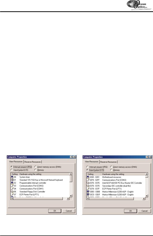
"If you have Windows 95/98, go to Start | Settings | Control Panel. Double-click the System icon. Choose the Device Manager tab and double-click on “Computer” at the top of the list of devices. Under View Resources, note available settings -- numbers unassigned to hardware (numbers not listed here). Remember that these I/O settings are expressed in hexadecimal and correspond to our Base Address, which is given in decimal, followed by the hexadecimal equivalent in parenthesis.
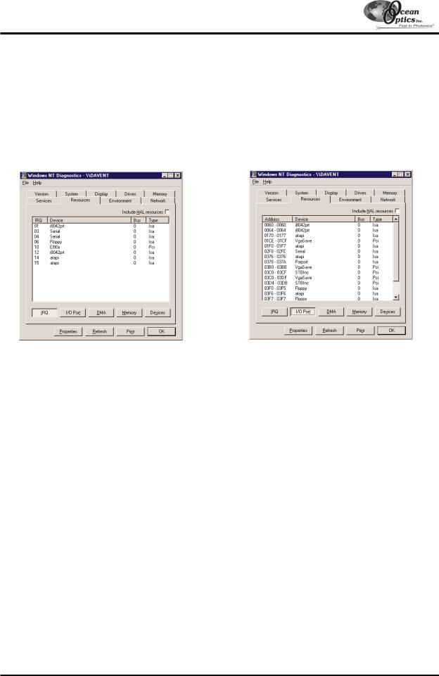
"If you have Windows NT, go to Start | Programs | Administrative Tools (Common) | Windows NT Diagnostics. Click on the Resources tab. Select the IRQ button. Find an available IRQ. Select the I/O Port button. Find an available I/O Range (Base Address).
"If you have Windows 2000, go to Start | Programs | Administrative Tools (Common) | Windows NT Diagnostics. Click on the Resources tab. Select the IRQ button. Find an available IRQ. Select the I/O Port button. Find an available I/O Range (Base Address).
2.Note these values as you will have to configure the switches on the A/D board to match these values. Also, when you first run OOIBase32, you must enter these values in the “Configure Hardware” dialog box.
3.Turn off the computer and take off the computer cover. Ground yourself to the computer chassis or power supply and remove the A/D card from its static-shielded bag.
4.If necessary, change the position of the switches on the A/D board. For the ADC500, the Base Address is set via the bank of 6 switches labeled SW1 on the A/D board and the IRQ is set via the bank of 4 switches labeled SW2 on the A/D board. For the ADC1000 and PC2000, there is only one bank of switches on the A/D board: the Base Address may be changed via the first 6 switches and the IRQ may be changed via the last 3 switches. (See Appendix A for switch positions.)
5.Insert the A/D card into the ISA-bus slot and connect the necessary cables from the A/D card to the spectrometer. Make sure the connections are snug and restart your computer.
If your A/D converter is the DAQ-700
1.Install NI-DAQ version 6 CD Driver Software -- the device driver library necessary for Windows 95/98 and NT systems to properly use the DAQ-700 on your computer.
2.Insert the DAQ-700 into any available PCMCIA slot.
3.Set the IRQ and Base Address values.
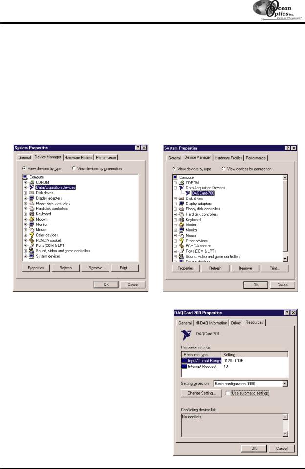
"If you have Windows 95/98, select Start | Settings | Control Panel. Double-click the System icon. Select the Device Manager tab. Double-click the hardware group named Data Acquisition Devices. Doubleclick DAQCard-700. Click the Resources tab. Find the check box next to Use Automatic Settings. Clear that check box (deselect it). Now change the settings for either (or both) the Input/Output Range or the Interrupt Request. To make this change, double-click either Input/Output Range or Interrupt Request. A dialog box giving the current hardware setting appears. Use the two small arrows to the right side of the Value box to change the hardware interface parameters. Choose values that say No devices are conflicting. Click OK. Click Yes at the “Creating a Forced Configuration” message box.
"If you have Windows NT, go to Start | Programs | Administrative Tools (Common) | Windows NT Diagnostics. Click on the Resources tab. Select the IRQ button. Find the IRQ that your computer assigned to the A/D converter. Select the I/O Port button. Find the I/O Range (Base Address) that your computer assigned to the DAQ-700.
-8 -

Quick Start
4.Note these values. When you first run OOIBase32, you must enter these values in the “Configure Hardware” dialog box.
If your A/D converter is the SAD500
If your A/D converter is the SAD500 and is mounted onto the spectrometer, connect the cable from the SAD500 to your PC. If you ordered your SAD500 in its own housing, attach another cable from the spectrometer to the SAD500. Note the serial port number (also called COM Port) on the PC to which you are interfacing. Plug the +12VDC wall transformer into an outlet and connect it to the SAD500.
Step 2: Install OOIBase32 Software
Before installing OOIBase32, make sure that no other applications are running.
1.Execute Setup.exe. At the “Welcome” dialog box, click Next>.
2.At the “Destination Location” dialog box, accept the default or choose Browse to pick a directory. Click Next>.
3.At the “Backup Replaced Files” dialog box, select either Yes or No. We recommend selecting Yes. If you select Yes, you can choose Browse to pick a destination directory. Click Next>.
4.Select a Program Manager Group. Click Next>. At the “Start Installation” dialog box, click Next>.
5.Follow all prompts regarding the Spectrometer Configuration diskette that came with your system.
6.At the “Installation Complete” dialog box, choose Finish>.
7.When prompted to do so, restart your computer when the installation is complete.
Step 3: Configure OOIBase32 Software
After you restart your computer, navigate to the OOIBase32 icon and select it. Now that your A/D converter and software have been installed, you need to configure your software. For details on using OOIBase32, refer to the
OOIBase32 Spectrometer Operating Software Manual.
Operator and Serial Number Dialog Box
First, a prompt to enter a user name and serial number appears. Some files will include this data in the header.
Default Spectrometer Configuration File
Next, a message appears asking you to select a default spectrometer configuration file. A file open dialog box then appears. You must choose the default spectrometer configuration file. Navigate to the OOIBase32 directory and choose the file with .spec as the extension. The .spec extension is preceded by the serial number of your spectrometer (I2J613.spec is an example of a spectrometer configuration filename).
Configure Hardware Dialog Box
Next, the Configure Hardware dialog box opens. The parameters in this dialog box are usually set only once -- when OOIBase32 is first installed and the software first opens. Choose the spectrometer and A/D converter you are using. For the Base Address and IRQ, choose available settings. If you have the SAD500, specify the same COM port number as the one being used to interface to your SAD500.
Spectrometer Configuration Dialog Box
Select Spectrometer | Configure from the menu and set system parameters. In the Wavelength Calibration page, the coefficients for your system were loaded as part of the .spec file. Check the Enabled box for each channel in your system. In the A/D Interface page, enter the same values as you did in the Configure Hardware dialog box. When you exit OOIBase32, this information is stored in the spectrometer configuration file.
OOIBase32 Settings Dialog Box
Choose Edit | Settings from the menu to configure OOIBase32 parameters in the OOIBase32 Settings dialog box. Go through each page of this dialog box to select options for saving, opening, and printing data; to choose waveform sound files for various program events; to configure default setting files; and to select other important options such as storing and copying data and choosing warning messages.
- 9 -
Quick Start
Configure Data Acquisition Dialog Box
Finally, select Spectrum | Configure Data Acquisition from the menu to open the Configure Data Acquisition dialog box and to set your data acquisition parameters such as the integration time, averaging and boxcar smoothing, and several other parameters.
Step 4: Connect Sampling Optics
For detailed information on connecting and operating sampling optics such as light sources, sampling chambers, fibers, or any other Ocean Optics spectroscopic accessory, check the Table of Contents to find operating instructions on a specific component.
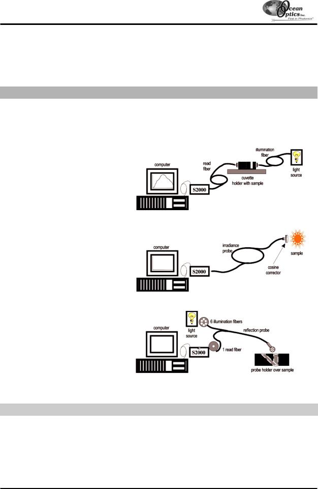
The following are typical configurations for absorbance, transmission, irradiance, and reflection experiments.
Absorbance/Transmission Setup
Irradiance Setup
Reflection Setup
Step 5: Start the Software and Receive Data
Run OOIBase32 in Scope Mode and take a dark spectrum and a reference spectrum (see the Experiment Tutorial section for details). Choose the absorbance, transmission, or relative irradiance mode to take your sample measurements. For detailed information on OOIBase32 functions and features, refer to the OOIBase32
Spectrometer Operating Software Manual.
- 10 -
S2000 Miniature Fiber Optic Spectrometers
Our second-generation miniature fiber optic spectrometer, the S2000, couples a low-cost, high-performance 2048-element linear CCD-array detector with an optical bench that's small enough to fit into the palm of your hand. The S2000 is a high-sensitivity, low-cost UV-VIS-Shortwave NIR spectrometer, making it especially useful for fluorescence and other low light level applications that demand high detector sensitivity. The S2000 has twice the number of CCD elements and is nearly 50x more sensitive than our original, revolutionary S1000 Miniature Fiber Optic Spectrometer.
The S2000 accepts light energy transmitted through single-strand optical fiber and disperses it via a fixed grating across the linear CCD array detector, which is responsive from 200-1100 m. Up to seven spectrometer
channels can be added to expand wavelength range, perform multiple tasks or provide reference monitoring. The master and slave channels are all accessed through a single program for near-synchronous operation.
In addition, an SMA 905 connector allows for easy coupling to an extensive line of fiber optic light sources, sampling chambers, optical fibers, probes, chemical sensors, and other spectrophotometric accessories. Ocean Optics offers nearly 500 spectrophotometric accessories that help to create fully integrated small-footprint tools for optical experimentation in the lab and in the field.
An S2000 Miniature Fiber Optic Spectrometer without its housing.
Operating performance will vary according to a number of factors, including the spectrometer configuration -- especially the groove density of the grating and the size of the entrance optics -- as well as the application itself.
Optical resolution -- measured as Full Width Half Maximum (FWHM) -- of a monochromatic source depends on the groove density (lines/mm) of the grating and the diameter of the entrance optics (optical fiber or slit). The following formulas approximately calculate the optical resolution of your system in nm (FWHM).
DISPERSION (nm/pixel) = |
Spectral range of the grating |
|
2048 (number of pixels or detector elements) |
RESOLUTION (in pixels) = typical values from slit size or fiber diameter (see below)
5 |
m slit = 3.0 pixels |
50 |
m slit = 6.5 pixels |
10 |
m slit = 3.2 pixels |
100 |
m slit = 12.0 pixels |
25 |
m slit = 4.2 pixels |
200 |
m slit = 24.0 pixels |
OPTICAL RESOLUTION (in nm) = DISPERSION X RESOLUTION
- 11 -
S2000 Miniature Fiber Optic Spectrometers
S2000 Specifications
Absolute Maximum Ratings
VCC |
+ 5.5 VDC |
Voltage on any pin |
VCC + 0.2 VDC |
Physical Specifications
Physical dimensions (no enclosure) |
5.47” x 3.90” x 0.75” LWH (master only) |
|
139 mm x 99 mm x 19 mm LWH (master only) |
||
|
||
Physical dimension (with enclosure) |
5.63” x 4.09” x 1.58” LWH (master only) |
|
143 mm x 104 mm x 40 mm LWH (master only) |
||
|
||
Weight |
200 g (master only, no enclosure) |
Power
Power requirement (master) |
130 mA at +5 VDC |
|
Power requirement (slave) |
70 mA at +5 VDC |
|
Supply voltage |
4.5 – 5.5 V |
|
Power-up time |
3 msec |
|
Spectrometer |
|
|
Design |
asymmetric crossed Czerny-Turner |
|
Focal length (input) |
42 mm |
|
Focal length (output) |
68 mm (75, 83 and 90 mm focal lengths are also available for some |
|
configurations) |
||
|
||
Input fiber connector |
SMA 905 |
|
Gratings |
14 different gratings |
|
Entrance slit |
5, 10, 25, 50, 100, or 200 µm slits. (Slits are optional. In the absence |
|
of a slit, the fiber acts as the entrance slit.) |
||
|
||
Detector |
Sony ILX511 CCD |
|
Filters |
2nd order rejection, long pass (optional) |
|
Spectroscopic |
|
|
Integration time |
3 – 65,000 msec |
|
Dynamic range |
2 x 10⁸ |
|
Signal-to-Noise |
250:1 single acquisition |
|
Readout noise (single dark spectrum) |
3.5 counts RMS, 20 counts peak-to-peak |
|
Resolution (FWHM) |
0.3 – 10.0 nm varies by configuration |
|
Stray light |
<0.05% at 600 nm; <0.10% at 435 nm |
|
Spectrometer channels |
8 (master plus up to 7 slaves) |
|
Environmental Conditions |
|
|
Temperature |
-30° - +70° C Storage; -10° - +60° C Operation |
- 12 -
S2000 Miniature Fiber Optic Spectrometers
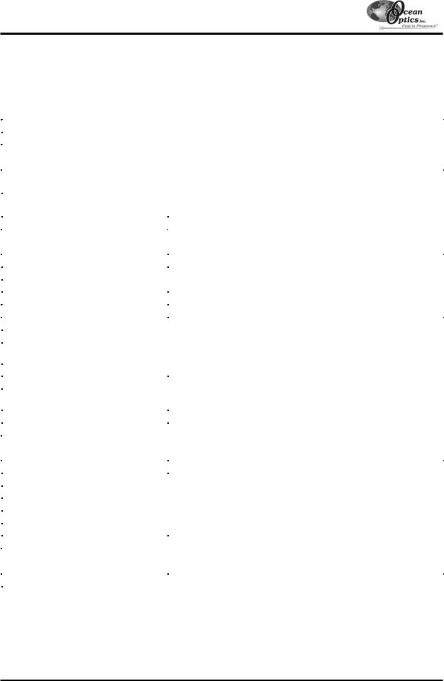
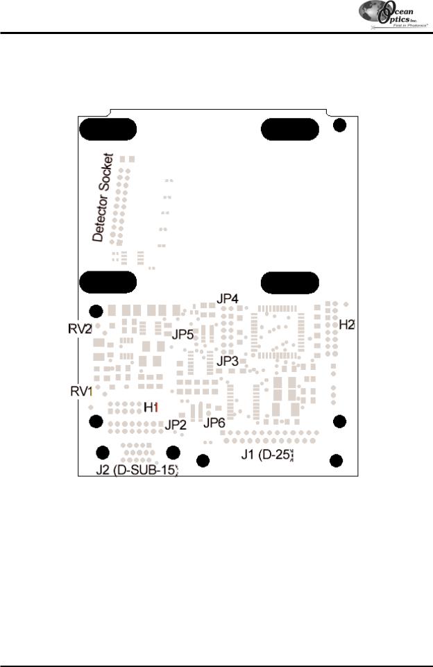
S2000 Board Layout
H1 |
Header Block connecting analog signals from slave spectrometer channel(s) to the Master spectrometer |
|
channel |
H2 |
Header Block containing digital control signals |
JP3 |
Jumper Block controlling of external strobing of a light source |
JP4 |
Jumper Block controlling externally triggered integration time of the spectrometer |
JP5 |
Reserved -- do not short |
JP6 |
Reserved -- do not short |
RV1 |
Potentiometer controlling the baseline |
RV2 |
Potentiometer controlling the gain (do not adjust) |
J1 |
A/D Converter interface cable connection |
J2 |
Accessory Cable connection |
- 13 -
A/D Converters
This section covers the basic installation instructions for our A/D converters: ADC500, ADC1000 (and PC2000), SAD500, and DAQ700. Because A/D converter installation goes hand-in-hand with software installation, you will find directions for installing OOIBase32 Spectrometer Operating Software included in this section. The A/D converters we offer are:
"ADC500 ISA-BUS A/D CONVERTER is a 12-bit, 8-channel, singleended, half-length card that fits into an ISA slot in a desktop PC and has 500 kHz sampling frequency.
"ADC1000 ISA-BUS A/D CONVERTER is a high-speed, 12-bit, 8-channel, single-ended, half-length card that fits into an ISA slot in a desktop PC and has 1 MHz sampling frequency.
"PC2000 PC PLUG-IN is an S2000 mounted onto an ADC1000 A/D card. This combination fits easily into an ISA slot in the PC; has 1 MHz sampling frequency.
"SAD500 SERIAL PORT INTERFACE is a 12-bit, 8-channel A/D converter for serial port connection for interfacing to desktop or notebook PCs and has 500 kHz sampling frequency.
"DAQ-700 PCMCIA A/D CONVERTER from National Instruments is a 12-bit, 16-channel, single-ended card that fits into a credit cardsize slot in a notebook PC and has 100 kHz sampling frequency.
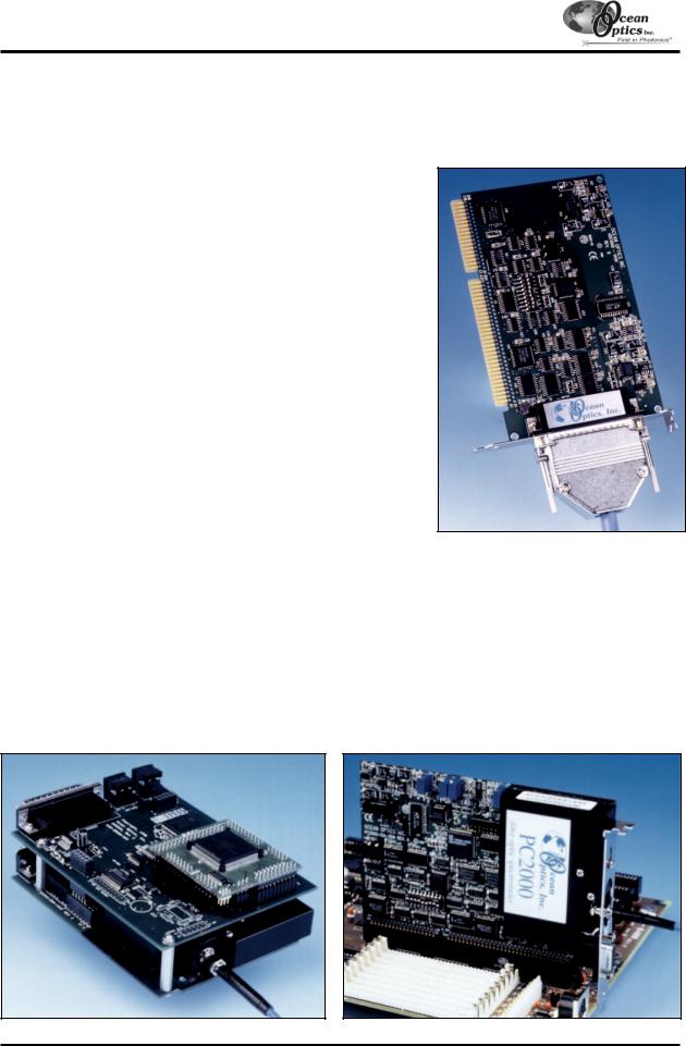
ADC1000 ISA-bus
A/D Converter
Our software includes drivers that support the A/D converters we offer. Other A/D converters can be used with our spectrometers if the following conditions are met:
1.the ADC sampling rate is at least 100 kHz
2.external triggering of the A/D conversions is supported
3.there are a sufficient number of clocks and digital output lines to operate the spectrometer
4.a suitable software driver has been written
5.a suitable cable has been fabricated
Other A/D converters and software can be used to control our products; however, you will need to create your own drivers. Contact one of our Applications Scientists for timing diagrams, pinouts, and other necessary engineering details.
SAD500 Serial Port Interface mounted onto an S2000
PC2000 Spectrometer
(S2000 mounted onto
an ADC1000
- 14 -
A/D Converters: ADC500
ADC500 ISA-bus A/D Converter
The ADC500 ISA-BUS A/D CONVERTER is a 12-bit, 8-channel ISA-bus analog-to-digital converter card that connects our spectrometers to desktop PCs. This single-ended, half-length card fits into an ISA slot in a desktop PC, and has a 500 kHz sampling frequency. The following are directions for installing your ADC500. Because A/D converter installation goes hand-in-hand with software installation, you will find directions for installing OOIBase32 Spectrometer Operating Software included in this section as well.
Each device in or connected to your computer is assigned specific settings; it’s similar to giving each device its own name so that your computer will know what to call and how to recognize the device. In order for your ADC500 to work as a device in your computer, it has to be assigned a Base Address setting and an IRQ setting. The default settings for each are: Base Address (I/O Range): 768 decimal (300 hexadecimal)
IRQ (Interrupt Request): 07
These default values are set on the A/D converter. There are dip switches on the A/D board and their positions determine the values. These default values are set in the operating software as well. Most of the time, these default settings will work with your computer. However, if you have many devices installed in your computer, you may have a conflict; other devices may be using these settings. If there is a conflict with another device in your computer, you must change the positions of the switches on the A/D board and change the values in the software.
For the ADC500, the Base Address is set via the bank of 6 switches labeled SW1 on the A/D board and the IRQ is set via the bank of 4 switches labeled SW2 on the A/D board. To first check your computer to see which settings are available, follow the instructions for your Windows operating system.
Windows 95 and Windows 98 Users:
Find Available Base Address and IRQ Settings
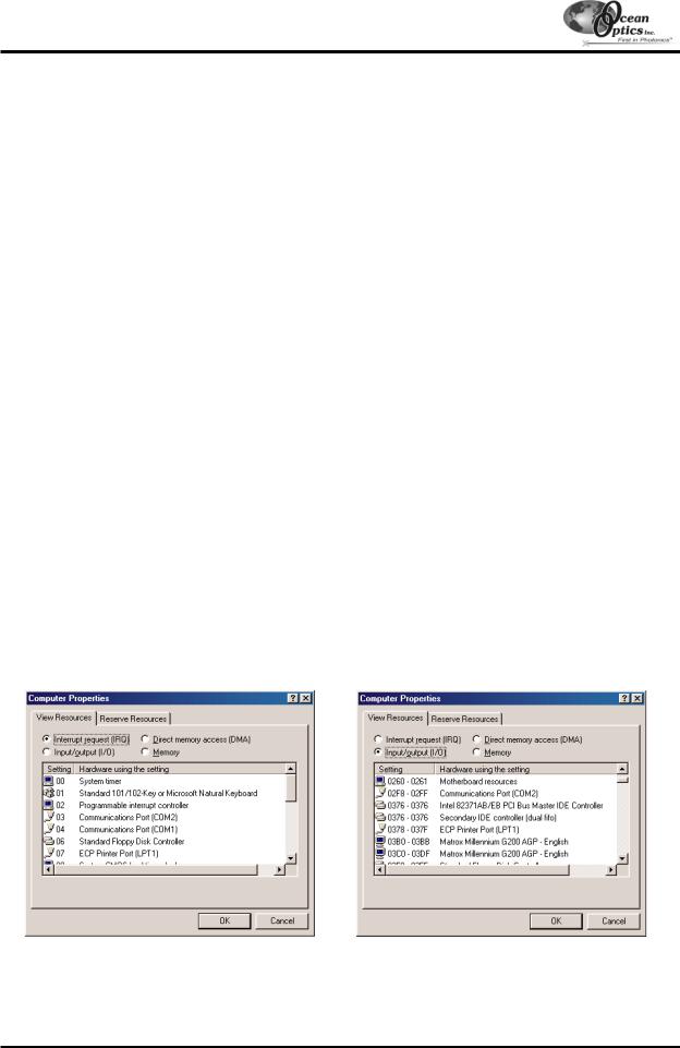
1.Go to Start | Settings | Control Panel and double-click on the System icon.
2.Choose the Device Manager tab and double-click on “Computer” at the top of the list.
3.Under View Resources, find available settings -- numbers unassigned to hardware. Note these available settings for both the Interrupt request (IRQ) and the Input/output (Base Address). When you first run OOIBase32, you must enter these values in the “Configure Hardware” dialog box. (Remember that Input/output settings are expressed in hexadecimal.)
!For most computers, the default settings work well. In the picture above left, it appears that the Printer occupies IRQ 07, but for most computers, our A/D converters can share the IRQ 07 setting with a printer and conflicts will not arise. All computers have multiple Base Address (Input/output) settings from which to choose.
-15 -
A/D Converters: ADC500
Windows NT Users:
Find Available Base Address and IRQ Settings
1.Go to Start | Programs | Administrative Tools (Common) | Windows NT Diagnostics.
2.In the “Windows NT Diagnostics” dialog box, click on the Resources tab.
3.Select the IRQ button. Find an available IRQ -- a number unassigned to a device.
4.Select the I/O Port button. Find an available I/O Range (Base Address) -- a number or range of numbers unassigned to a device. (The number is in hexadecimal.)
5.Note these available settings. When you first run OOIBase32, you must enter these values in the “Configure Hardware” dialog box.
! With Windows NT, devices cannot share IRQs; each device must be assigned a unique IRQ.
Install the ADC500
1.Turn off the computer and remove the computer cover.
2.Ground yourself to the computer chassis or power supply and remove the A/D card from its static-shielded bag.
3.If necessary, change the position of the switches on the A/D board. Position the switches to match the available settings you found in the previous section -- numbers not being used by other hardware devices. See Appendix A for switch setting positions.
4.Find an open ISA-bus slot and remove the slot protector.
5.Insert the A/D card into an available expansion slot on the motherboard by gently rocking the card into the slot. Make sure the card is fully seated in the motherboard before screwing the tab on the A/D card to the computer. Do not bend the card or move it from side to side once it is seated in the slot.
6.Attach the D37 end of the cable to the card and the D25 end to the spectrometer. Reinstall the cover.
Install OOIBase32
Before installing OOIBase32, make sure that no other applications are running.
1.Execute Setup.exe.
2.At the “Welcome” dialog box, click Next>.
3.At the “Destination Location” dialog box, accept the default or choose Browse to pick a directory. Click Next>.
4.At the “Backup Replaced Files” dialog box, select either Yes or No. We recommend selecting Yes. If you select Yes, accept the default or choose Browse to pick a destination directory. Click Next>.
5.Select a Program Manager Group. Click Next>. At the “Start Installation” dialog box, click Next>.
6.Follow all prompts regarding the Spectrometer Configuration diskette that came with your system.
7.At the “Installation Complete” dialog box, choose Finish>.
8.When prompted to do so, restart your computer when the installation is complete.
-16 -
A/D Converters: ADC500
Run OOIBase32
After you restart your computer, navigate to the OOIBase32 icon and select it. The first time you run OOIBase32 after installation, you must follow several prompts before you can begin taking measurements.
Operator and Serial Number Dialog Box
First, a prompt to enter a user name and serial number appears. Certain data files will include this information in the header. (If, at a later date, you wish to change the operator name and serial number, select Edit | Settings from the menu and then choose the Registration tab.) Click OK.
Default Spectrometer Configuration File
Next, the following message appears:
This appears to be the first time OOIBase32 has been executed. Please select a default spectrometer configuration file from the following screen. This spectrometer configuration file will be used each time OOIBase32 is started.
A file open dialog box then appears. Navigate to the OOIBase32 directory, and choose the default spectrometer configuration file -- the file with .spec as the extension, preceded by the serial number of your spectrometer. (A default spectrometer configuration file will be named something similar to I2J613.spec.)
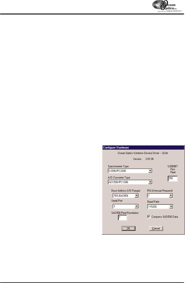
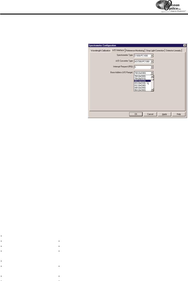
Configure Hardware Dialog Box
Next, the Configure Hardware dialog box opens. The parameters in this dialog box are usually set only once -- when OOIBase32 is first installed and the software first opens.
1.Under Spectrometer Type, choose your spectrometer.
2.Under A/D Converter Type, choose ADC500/PC1000.
3.Under Base Address, choose the same setting as the dip switches on the A/D board (and the same available setting you found in your computer).
Remember that the Input/output Range (Base Address) you selected was expressed in hexadecimal. In this dialog box, the base address is given in decimal, followed by the hexadecimal equivalent in parenthesis. For example, “768 (0x0300)” gives the base address as 768 decimal and 300 hexadecimal.
4.Under IRQ, choose the same setting as the dip switches on the A/D board (and the same available setting you found in your computer).
5.For your setup, only these parameters apply. (Ignore the other settings; they apply to other A/D converters.) Click OK. You can always change these settings once
OOIBase32 is fully operational by selecting Spectrometer | Configure | A/D Interface.
!If you do not see the “Configure Hardware” screen, exit the software. Then select Start | Run, and type
C:\windows\ooidrv.ini for Windows 95/98 systems or c:\winnt\ooidrv.ini for Windows NT systems. Notepad will open. Edit this file for our device driver by finding the “Initialized” entry and making sure this line reads Initialized=0. Save the OOIDRV.INI file and exit Notepad. Restart OOIBase32. You should now see the “Configure Hardware” dialog box.
-17 -
A/D Converters: ADC500
Spectrometer Configuration Dialog Box
Now that OOIBase32 is running, you need to configure your system. Select Spectrometer | Configure from the menu. Go through each page in the Spectrometer Configuration dialog box to set system parameters. (See the
OOIBase32 Spectrometer Operating Software Manual for details.)
"In the Wavelength Calibration page, the coefficients for each spectrometer channel in your system have already been loaded as part of the spectrometer configuration file. Check the Enabled box for each spectrometer channel in your system.
"In the A/D Interface page, enter the same values as you did in the Configure Hardware dialog box.
"The Detector Linearity page in this dialog box allows you to enter coefficients for an algorthim that corrects for rare occurances of non-linearity of the detector. Contact Ocean Optics for more information.
Save the spectrometer configuration file by choosing Spectrometer | Save Configuration As
from the OOIBase32 menu. You can rename the file or use the default file name ([your serial number].spec). You will then be asked if you would like to make this file the default spectrometer configuration file. Choose Yes. The next time you run OOIBase32, the software will use the file as the standard for your spectrometer configuration. When you exit OOIBase32, any changes to the configuration file will be automatically saved to the default file.
OOIBase32 Settings Dialog Box
At this point, it is a good idea to configure several OOIBase32 operation parameters. Choose Edit | Settings from the menu to open the OOIBase32 Settings dialog box. Go through each page of this dialog box to select options for saving, opening, and printing data; to configure default setting files; and to select other important options such as storing and copying data and choosing warning messages. (See the OOIBase32 Spectrometer Operating Software Manual for details.)
Configure Data Acquisition Dialog Box
Finally, select Spectrum | Configure Data Acquisition from the menu to set your data acquisition parameters in the Configure Data Acquisition dialog box. The Basic page allows you to set the integration time and choose averaging and boxcar smoothing values. The External Trigger page allows you to specify the external trigger mode. The Strobe page allows you to control external strobe events with the spectrometer. (See the OOIBase32 Spectrometer Operating Software Manual for details.)
|
|
Specifications |
|
|
|
|
|
|
Board architecture/design: |
half-length ISA-bus card for single slot in desktop PC |
|
|
Resolution: |
12-bit |
|
|
Sampling frequency: |
500 kHz (maximum) |
|
|
Interface cable: |
37-pin end to A/D card, 25-pin end to spectrometer |
|
|
length is ~3.5' (slightly >1 meter) |
|
|
|
|
|
|
|
Multiple-channel capability: |
supports up to 8 spectrometer channels |
|
|
Installation parameters: |
set dip switch for Base Address (default = 768 decimal, 300 hexadecimal) |
|
|
set dip switch for IRQ (default = 7) |
|
|
|
|
|
|
|
Integration time: |
5 milliseconds to 60 seconds with S2000 series spectrometers |
|
|
|
|
|
|
|
- 18 - |
|
A/D Converters: ADC1000 (and PC2000)
ADC1000 ISA-bus A/D Converter (and PC2000)
The ADC1000 ISA-BUS A/D CONVERTER is a 12-bit, 8-channel, single-ended A/D card that connects our spectrometers to desktop PCs. The PC2000 PC PLUG-IN SPECTROMETER has our 2048-element linear CCD-array fiber optic spectrometer mounted onto an ADC1000. This sturdy combination fits easily into a slot in the PC. The following are directions for installing your ADC1000 and PC2000. Because A/D converter installation goes hand-in- hand with software installation, you will find directions for installing OOIBase32 Spectrometer Operating Software included in this section as well.
Each device in or connected to your computer is assigned specific settings; it’s similar to giving each device its own name so that your computer will know what to call and how to recognize the device. In order for your ADC1000 or PC2000 to work as a device in your computer, it has to be assigned a Base Address setting and an IRQ setting. The default settings for each are: Base Address (I/O Range): 768 decimal (300 hexadecimal)
IRQ (Interrupt Request): 07
These default values are set on the A/D converter. There are dip switches on the A/D board and their positions determine the values. These default values are set in the operating software as well. Most of the time, these default settings will work with your computer. However, if you have many devices installed in your computer, you may have a conflict; other devices may be using these settings. If there is a conflict with another device in your computer, you must change the positions of the switches on the A/D board and change the values in the software.
For the ADC1000 and PC2000, there is only one bank of switches on the A/D board: the Base Address may be changed via the first 6 switches and the IRQ may be changed via the last 3 switches. To first check your computer to see which settings are available, follow the instructions for your Windows operating system.
Windows 95 and Windows 98 Users:
Find Available Base Address and IRQ Settings
1.Go to Start | Settings | Control Panel and double-click on the System icon.
2.Choose the Device Manager tab and double-click on “Computer” at the top of the list.
3.Under View Resources, find available settings -- numbers unassigned to hardware. Note these available settings for both the Interrupt request (IRQ) and the Input/output (Base Address). When you first run OOIBase32, you must enter these values in the “Configure Hardware” dialog box. (Remember that Input/output settings are expressed in hexadecimal.)
!For most computers, the default settings work well. In the picture above left, it appears that the Printer occupies IRQ 07, but for most computers, our A/D converters can share the 07 setting with a printer and conflicts will not arise. All computers have multiple Base Address (Input/output) settings from which to choose.
-19 -

A/D Converters: ADC1000 (and PC2000)
Windows NT Users:
Find Available Base Address and IRQ Settings
1.Go to Start | Programs | Administrative Tools (Common) | Windows NT Diagnostics.
2.In the “Windows NT Diagnostics” dialog box, click on the Resources tab.
3.Select the IRQ button. Find an available IRQ -- a number unassigned to a device.
4.Select the I/O Port button. Find an available I/O Range (Base Address) -- a number or range of numbers unassigned to a device. (The number is in hexadecimal.)
5.Note these available settings. When you first run OOIBase32, you must enter these values in the “Configure Hardware” dialog box.
! With Windows NT, devices cannot share IRQs; each device must be assigned a unique IRQ.
Install the ADC1000 or PC2000
1.Turn off the computer and remove the computer cover.
2.Ground yourself to the computer chassis or power supply and remove the A/D card from its static-shielded bag.
3.If necessary, change the position of the switches on the A/D board. Position the switches to match the available settings you found in the previous section -- numbers not being used by other hardware devices. See Appendix A for switch setting positions.
4.Find an open ISA-bus slot and remove the slot protector.
5.Insert the A/D card into an available expansion slot on the motherboard by gently rocking the card into the slot. Make sure the card is fully seated in the motherboard before screwing the tab on the A/D card to the computer. Do not bend the card or move it from side to side once it is seated in the slot.
6.For the ADC1000, attach the D37 end of the cable to the card and the D25 end to the spectrometer. For the PC2000, attach the desired optical fiber to the SMA connector on the PC2000. Reinstall the cover.
Install OOIBase32
Before installing OOIBase32, make sure that no other applications are running.
1.Execute Setup.exe.
2.At the “Welcome” dialog box, click Next>.
3.At the “Destination Location” dialog box, accept the default or choose Browse to pick a directory. Click Next>.
4.At the “Backup Replaced Files” dialog box, select either Yes or No. We recommend selecting Yes. If you select Yes, accept the default or choose Browse to pick a destination directory. Click Next>.
5.Select a Program Manager Group. Click Next>. At the “Start Installation” dialog box, click Next>.
6.Follow all prompts regarding the Spectrometer Configuration diskette that came with your system.
7.At the “Installation Complete” dialog box, choose Finish>.
8.When prompted to do so, restart your computer when the installation is complete.
-20 -
A/D Converters: ADC1000 (and PC2000)
Run OOIBase32
After you restart your computer, navigate to the OOIBase32 icon and select it. The first time you run OOIBase32 after installation, you must follow several prompts before you can begin taking measurements.
Operator and Serial Number Dialog Box
First, a prompt to enter a user name and serial number appears. Certain data files will include this information in the header. (If, at a later date, you wish to change the operator name and serial number, select Edit | Settings from the menu and then choose the Registration tab.) Click OK.
Default Spectrometer Configuration File
Next, the following message appears:
This appears to be the first time OOIBase32 has been executed. Please select a default spectrometer configuration file from the following screen. This spectrometer configuration file will be used each time OOIBase32 is started.
A file open dialog box then appears. Navigate to the OOIBase32 directory, and choose the default spectrometer configuration file -- the file with .spec as the extension, preceded by the serial number of your spectrometer. (A default spectrometer configuration file will be named something similar to I2J613.spec.)
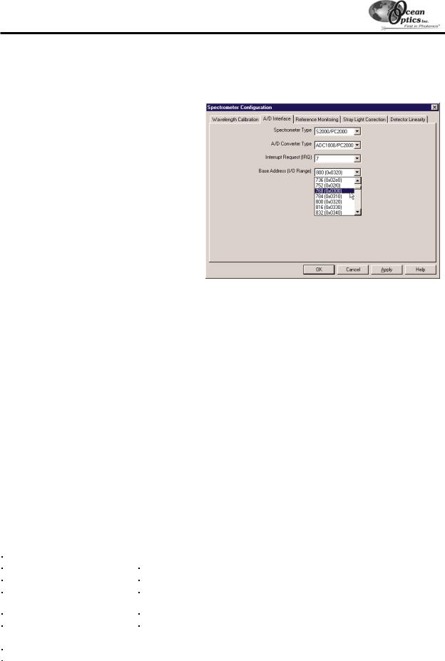
Configure Hardware Dialog Box
Next, the Configure Hardware dialog box opens. The parameters in this dialog box are usually set only once -- when OOIBase32 is first installed and the software first opens.
1.Under Spectrometer Type, choose S2000/PC2000.
2.Under A/D Converter Type, choose ADC1000/PC2000.
3.Under Base Address, choose the same setting as the dip switches on the A/D board (and the same available setting you found in your computer).
Remember that the Input/output Range (Base Address) you selected was expressed in hexadecimal. In this dialog box, the base address is given in decimal, followed by the hexadecimal equivalent in parenthesis. For example, “768 (0x0300)” gives the base address as 768 decimal and 300 hexadecimal.
4.Under IRQ, choose the same setting as the dip switches on the A/D board (and the same available setting you found in your computer).
5.For your setup, only these parameters apply. (Ignore the other settings; they apply to other A/D converters.) Click OK. You can always change these settings once OOIBase32 is fully operational by selecting
Spectrometer | Configure | A/D Interface.
!If you do not see the “Configure Hardware” screen, exit the software. Then select Start | Run and type
C:\windows\ooidrv.ini for Windows 95/98 systems or c:\winnt\ooidrv.ini for Windows NT systems. Notepad will open. Edit this file for our device driver by finding the “Initialized” entry and making sure this line reads Initialized=0. Save the OOIDRV.INI file and exit Notepad. Restart OOIBase32. You should now see the “Configure Hardware” dialog box.
-21 -
A/D Converters: ADC1000 (and PC2000)
Spectrometer Configuration Dialog Box
Now that OOIBase32 is running, you need to configure your system. Select Spectrometer | Configure from the menu. Go through each page in the Spectrometer Configuration dialog box to set system parameters. (See the
OOIBase32 Spectrometer Operating Software Manual for details.)
"In the Wavelength Calibration page, the coefficients for each spectrometer channel in your system have already been loaded as part of the spectrometer configuration file. Check the Enabled box for each spectrometer channel in your system.
"In the A/D Interface page, enter the same values as you did in the Configure Hardware dialog box.
"The Detector Linearity page in this dialog box allows you to enter coefficients for an algorthim that corrects for rare occurances of non-linearity of the detector. Contact Ocean Optics for more information.
Save the spectrometer configuration file by choosing Spectrometer | Save Configuration As
from the OOIBase32 menu. You can rename the file or use the default file name ([your serial number].spec). You will then be asked if you would like to make this file the default spectrometer configuration file. Choose Yes. The next time you run OOIBase32, the software will use the file as the standard for your spectrometer configuration. When you exit OOIBase32, any changes to the configuration file will be automatically saved to the default file.
OOIBase32 Settings Dialog Box
At this point, it is a good idea to configure several OOIBase32 operation parameters. Choose Edit | Settings from the menu to open the OOIBase32 Settings dialog box. Go through each page of this dialog box to select options for saving, opening, and printing data; to configure default setting files; and to select other important options such as storing and copying data and choosing warning messages. (See the OOIBase32 Spectrometer Operating Software Manual for details.)
Configure Data Acquisition Dialog Box
Finally, select Spectrum | Configure Data Acquisition from the menu to set your data acquisition parameters in the Configure Data Acquisition dialog box. The Basic page allows you to set the integration time and choose averaging and boxcar smoothing values. The External Trigger page allows you to specify the external trigger mode. The Strobe page allows you to control external strobe events with the spectrometer. (See the OOIBase32 Spectrometer Operating Software Manual for details.)
|
|
Specifications |
|
|
|
|
|
|
Board architecture/design: |
half-length ISA-bus card for single slot in desktop PC |
|
|
Resolution: |
12-bit |
|
|
Sampling frequency: |
1 MHz (maximum) |
|
|
Interface cable: |
For the ADC1000: 37-pin connector to A/D card and 25-pin connector to |
|
|
spectrometer |
|
|
|
|
|
|
|
Multiple-channel capability: |
up to 8 spectrometer channels for S2000/PC2000 spectrometers |
|
|
Installation parameters: |
set dip switch for Base Address (default = 768 decimal, 300 hexadecimal) |
|
|
set dip switch for IRQ (default = 7) |
|
|
|
|
|
|
|
Integration time: |
3 milliseconds to 60 seconds with S2000 series spectrometers |
|
|
|
|
|
|
|
- 22 - |
|

A/D Converters: SAD500
SAD500 Serial Port Interface
The SAD500 SERIAL PORT INTERFACE is a microprocessor-controlled A/D converter for serial port connection or stand-alone operation. The SAD500 can be used to interface to desktop or portable PCs, PLCs, and other devices that support the RS-232 communication protocol. The following are directions for setting up your SAD500.
Because A/D converter installation goes hand-in-hand with software installation, you will find directions for installing OOIBase32 Spectrometer Operating Software included in this section as well.
Interface the SAD500 to your PC
Interfacing the SAD500 to a desktop or portable PC is simple.
1.If you ordered your SAD500 mounted onto your spectrometer, simply connect the 6-pin DIN end of the serial cable to the SAD500 and the DB9 end to your PC. If you ordered your SAD500 in its own housing, attach the 25-pin conductor ribbon cable from the spectrometer to the SAD500. Then connect the 6-pin DIN end of the serial cable to the SAD500 and the DB9 end to your PC.
2.For either configuration, note the serial port number (also called COM Port ) on the PC to which you are interfacing. (Older PCs may not have numbered ports.)
3.Plug the +12VDC wall transformer into an outlet and connect it to the SAD500.
Install OOIBase32
Before installing OOIBase32, make sure that no other applications are running.
1.Execute Setup.exe.
2.At the “Welcome” dialog box, click Next>.
3.At the “Destination Location” dialog box, accept the default or choose Browse to pick a directory. Click Next>.
4.At the “Backup Replaced Files” dialog box, select either Yes or No. We recommend choosing Yes. If you select Yes, you can choose Browse to pick a destination directory. Click Next>.
5.Select a Program Manager Group. Click Next>. At the “Start Installation” dialog box, click Next>.
6.Follow all prompts regarding the Spectrometer Configuration diskette that came with your system.
7.At the “Installation Complete” dialog box, choose Finish>.
8.When prompted to do so, restart your computer when the installation is complete.
Run OOIBase32
After you restart your computer, navigate to the OOIBase32 icon and select it. The first time you run OOIBase32 after installation, you must follow several prompts before you can begin taking measurements.
Operator and Serial Number Dialog Box
First, a prompt to enter a user name and serial number appears. Certain data files will include this information in the header. (If, at a later date, you wish to change the operator name and serial number, select Edit | Settings from the menu and then choose the Registration tab.) Click OK.
Default Spectrometer Configuration File
Next, the following message appears:
This appears to be the first time OOIBase32 has been executed. Please select a spectrometer configuration file from the following screen. This spectrometer configuration file will be used each time OOIBase32 is started.
A file open dialog box then appears. Navigate to the OOIBase32 directory, and choose the default spectrometer configuration file -- the file with .spec as the extension, preceded by the serial number of your spectrometer. (A default spectrometer configuration file will be named something similar to I2J613.spec.)
- 23 -
A/D Converters: SAD500
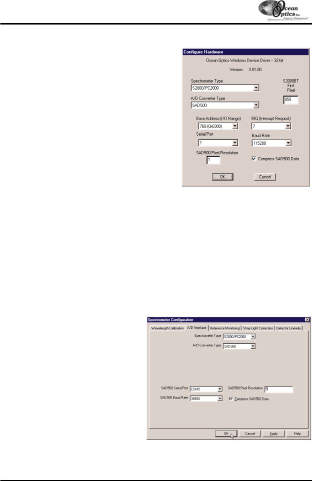
Configure Hardware Dialog Box
Next, the Configure Hardware dialog box opens. The parameters in this dialog box are usually set only once -- when OOIBase32 is first installed and the software first runs.
1.Under Spectrometer Type, choose your spectrometer.
2.Under A/D Converter Type, choose SAD500.
3.Under Serial Port, choose the COM port number your computer is using to interface to your SAD500. See the Troubleshooting section to determine the COM Port.
4.Under Baud Rate, select the speed at which the SAD500 will operate. (We recommend using 115,200 baud rate.)
5.Under SAD Pixel Resolution, enter resolution values from 1 to 500. This value specifies that every nth pixel of the spectrometer is transmitted from the SAD500 to the PC. Your resolution value depends on your experiment. By sacrificing resolution, you gain speed. The transfer of one complete spectra requires ~0.4 seconds when communicating at 115,200 baud rate. If you need your information in <0.4 seconds, increase the resolution or enable data compression (see below).
6.Enable the Compress SAD500 Data function to minimize the amount of data transferred over the
RS-232 connection. Transmission of spectral data over the serial port is a relatively slow process. Enabling this function ensures that every scan transmitted by the SAD500 will be compressed, greatly increasing the data transfer speed of the SAD500.
7.For your setup, only these parameters apply to your system. (Ignore the other settings; they apply to other A/D converters.) Click OK. You can always change these settings once OOIBase32 is fully operational by selecting
Spectrometer | Configure | A/D Interface.
!If you do not see the “Configure Hardware” screen, exit the software. Then select Start | Run, and type
C:\windows\ooidrv.ini for Windows 95/98 systems or c:\winnt\ooidrv.ini for Windows NT systems. Notepad will open. Edit this file for our device driver by finding the “Initialized” entry and making sure this line reads Initialized=0. Save the OOIDRV.INI file and exit Notepad. Restart OOIBase32. You should now see the “Configure Hardware” dialog box.
Spectrometer Configuration Dialog Box
Now that OOIBase32 is running, you need to configure your system. Select Spectrometer | Configure from the menu. Go through each page in the Spectrometer Configuration dialog box to set system parameters. (See the
OOIBase32 Spectrometer Operating Software Manual for details.)
"In the Wavelength Calibration page, the coefficients for each spectrometer channel have already been loaded as part of the spectrometer configuration file. Check the Enabled box for each spectrometer channel in your system.
"In the A/D Interface page, enter the same settings and values as you did in the
Configure Hardware dialog box.
"The Detector Linearity page in this dialog box allows you to enter coefficients for an algorthim that corrects for rare occurances of non-linearity of the detector. Contact Ocean Optics for more information.
-24 -

A/D Converters: SAD500
Save the spectrometer configuration file by choosing Spectrometer | Save Configuration As from the OOIBase32 menu. You can rename the file or use the default file name ([your serial number].spec). You will then be asked if you would like to make this file the default spectrometer configuration file. Choose Yes. The next time you run OOIBase32, the software will use the file as the standard for your configuration. When you exit OOIBase32, any changes to the configuration file will be automatically saved to the default file.
OOIBase32 Settings Dialog Box
At this point, it is a good idea to configure several OOIBase32 operation parameters. Choose Edit | Settings from the menu to open the OOIBase32 Settings dialog box. Go through each page of this dialog box to select options for saving, opening, and printing data; to configure default setting files; and to select other important options such as storing and copying data and choosing warning messages. (See the OOIBase32 Spectrometer Operating Software Manual for details.)
Configure Data Acquisition Dialog Box
Finally, select Spectrum | Configure Data Acquisition from the menu to set your data acquisition parameters in the Configure Data Acquisition dialog box. The Basic page allows you to set the integration time and choose averaging and boxcar smoothing values. The External Trigger page allows you to specify the external trigger mode. The Strobe page allows you to control external strobe events with the spectrometer. (See the OOIBase32 Spectrometer Operating Software Manual for details.)
Troubleshooting
Occasionally, there will be problems associated with your PC configuration and the software. Here are a few tips to assist you.
"To ensure that the software and hardware are in-synch, exit OOIBase32, cycle power on the SAD500, and restart OOIBase32.
"In Windows 95/98, you can find out your Serial Port number by selecting Start | Settings | Control Panel. Then double-click on the System icon and select the Device Manager tab. Double-click on Ports (COM & LPT) to display the COM port numbers. Ensure that there is no yellow or red warning sign next to the COM Port you are attempting to use.
"If the ports on your PC are not labeled and you don’t know which COM port you are using for your SAD500, you may have to resort to trial and error. If you choose the wrong serial port number, you will not see a dynamic trace responding to light near the bottom of the displayed graph. Instead, you will see a straight line.
"On some computers, users may have to disable any virus protection software to ensure timely and complete transfer of the data.
|
Specifications |
|
|
A/D resolution: |
12-bit |
A/D sampling frequency: |
500 kHz (maximum) |
Communication port: |
RS-232 |
Baud rate: |
2400-115,200 |
Input voltage: |
10 – 24V |
Input current: |
130 mA without spectrometer |
Interface cable: |
6-pin DIN connector to PC, 25-pin connector to spectrometer |
Multiple-channel capability: |
supports up to 8 spectrometer channels |
Spectrometer integration time: |
5 milliseconds to 60 seconds (S2000 spectrometers) |
- 25 -

A/D Converters: DAQ-700
DAQ-700 PCMCIA A/D Converter
The DAQ-700 PCMCIA A/D CONVERTER is a 12-bit analog-to-digital converter card that connects our spectrometers to notebook PCs. This 16-channel single-ended, 8-channel differential card -- also known by its National Instruments DAQCard-700 designation -- fits into a credit card-size slot in a notebook PC. It has a 100 kHz sampling frequency.
Before using your spectrometer, you must first configure your computer to properly detect and use the DAQ-700 and then follow several steps to use it as an interface to your Ocean Optics spectrometer. The following are directions for setting up your DAQ-700. Because A/D converter installation goes hand-in-hand with software installation, you will find directions for installing OOIBase32 Spectrometer Operating Software included in this section as well.
Install OOIBase32
Before installing OOIBase32, make sure that no other applications are running.
1.Execute Setup.exe. At the “Welcome” dialog box, click Next>.
2.At the “Destination Location” dialog box, accept the default or choose Browse to pick a directory. Click Next>.
3.At the “Backup Replaced Files” dialog box, select either Yes or No. We recommend selecting Yes. If you select Yes, accept the default or choose Browse to pick a destination directory. Click Next>.
4.Select a Program Manager Group. Click Next>. At the “Start Installation” dialog box, click Next>.
5.Follow all prompts regarding the Spectrometer Configuration diskette that came with your system.
6.At the “Installation Complete” dialog box, choose Finish>.
7.When prompted to do so, restart your computer when the installation is complete.
8.Do not run OOIBase32 at this time. Your computer must be properly configured to use the DAQ-700 before you can use OOIBase32.
Install NI-DAQ
Windows 95/98 and NT users must install NI-DAQ Driver Software -- the device driver library necessary for Windows 95/98/NT systems to properly use the DAQ-700.
1.Insert your NI-DAQ version 6 CD into your CD-ROM drive.
2.After you insert your CD, a setup program should automatically start. If it does not, run the Setup.exe program from the CD.
3.The installation program has an option called Install NI-DAQ. Select that option.
4.In the “Select Components” dialog box, make sure NI-DAQ Driver Files (Minimal Install) is checked. Choose any of the other options you wish to install. Click Next>.
5.Accept the default destination directory and the default Program Group.
6.In the “Ready to Install” dialog box, click Next>. When prompted to do so, restart your computer. You must restart your computer at this time.
Install the DAQ-700
1.After the computer restarts, wait until all disk drive activity stops -- that is, wait until your computer is completely restarted. Connect the spectrometer cable between your DAQ-700 and your spectrometer.
2.Insert the DAQ-700 into any available PCMCIA slot.
3.Windows 95/98 will play a sound consisting of two tones of increasing pitch. If you do not hear this sound, and you do have internal speakers in your notebook computer, try turning the speaker volume up and reinserting the DAQ-700. If you still do not hear the “happy” sound, contact our Technical Support Department.
4.To find IRQ and Base Address values, follow the instructions for your Windows operating system.
-26 -
A/D Converters: DAQ-700
For Windows 95/98 Users:
Configure the DAQ-700
1.If you hear the “happy” sound, click Start, and select Settings | Control Panel.
2.Double-click the System icon. Select the Device Manager tab.
3.In the “Device Manager” dialog box, find the hardware group named Data Acquisition Devices. Either double-click the group or select the group and click Properties.
4.Under the Data Acquisition Devices group, find the entry for your DAQ-700. Either double-click DAQCard700, or select the entry and click Properties.
5.Once you have selected your DAQCard-700 from the Device Manager, click the Resources tab. The entries here control the hardware interface to your DAQ-700.
6.In this dialog box, find the check box next to Use automatic settings. Clear that check box (deselect it).
7.In the same dialog box, you will see entries for Input/Output Range and Interrupt Request. The Input/Output Range corresponds to the Base Address, and the Interrupt Request corresponds to the IRQ in our software. By deselecting the Use automatic settings box in the previous step, you disabled Plug- and-Play for the DAQ-700. But in order to fully disable Plug-and-Play, you must also change the settings for either (or both) the Input/Output Range or the Interrupt Request. To make this change, doubleclick either Input/Output Range or Interrupt Request. A dialog box giving the current hardware setting appears. On the right side of the Value box are two small arrows: one up and one down. You must use these arrows to change the hardware interface parameters of either the Input/Output Range or the Interrupt Request.
-27 -

A/D Converters: DAQ-700
8.While making this change, notice the Conflict information area at the bottom. Make sure you choose a value that says No devices are conflicting. If it shows a conflict, you must select a different value. After selecting values with no conflicts, click OK. You will then see the “Creating a Forced Configuration” message box. Click Yes.
9.Note your values of both the Input/Output Range (Base Address) and the Interrupt Request (IRQ). When you first run OOIBase32, you must enter these values in the “Configure Hardware” dialog box.
For Windows NT Users:
Find the IRQ and I/O Range
1.If you hear the “happy” sound, go to Start | Programs | Administrative Tools (Common) | Windows NT Diagnostics.
2.In the “Windows NT Diagnostics” dialog box, click on the Resources tab.
3.Select the IRQ button. Find the IRQ that your computer assigned to the DAQ-700. Note this number.
4.Select the I/O Port button. Find the I/O Range (Base Address) that your computer assigned to the DAQ-700. Note this number. (This number is in hexadecimal.)
- 28 -

A/D Converters: DAQ-700
Run OOIBase32
After you restart your computer, navigate to the OOIBase32 icon and select it. The very first time you run OOIBase32 after installation, you must follow several prompts before you can begin taking measurements.
Operator and Serial Number Dialog Box
First, a prompt to enter a user name and serial number appears. Certain data files will include this information in the header. (If, at a later date, you wish to change the operator name and serial number, select Edit | Settings from the menu and then choose the Registration tab.) Click OK.
Default Spectrometer Configuration File
Next, the following message appears:
This appears to be the first time OOIBase32 has been executed. Please select a spectrometer configuration file from the following screen. This spectrometer configuration file will be used each time OOIBase32 is started.
A file open dialog box then appears. Navigate to the OOIBase32 directory, and choose the default spectrometer configuration file -- the file with .spec as the extension, preceded by the serial number of your spectrometer. (A default spectrometer configuration file will be named something similar to I2J613.spec.)
Configure Hardware Dialog Box
Next, the Configure Hardware dialog box opens. The parameters in this dialog box are usually set only once -- when OOIBase32 is first installed and the software first opens.
1.Under Spectrometer Type, choose your spectrometer.
2.Under A/D Converter Type, choose DAQ700.
3.If you are a Windows 95/98 user, choose the same Base Address value selected in steps 8 and 9 on page 28. If you are a Windows NT user, choose the same Base Address value selected in step 4 in the section on page 28.
The I/O Range (Base Address) you selected was expressed in hexadecimal. In this dialog box, the Base Address is given in decimal, followed by the hexadecimal equivalent in parenthesis. For example, “768 (0x0300)” is 768 decimal, 300 hexadecimal.
4.If you are a Windows 95/98 user, choose the same IRQ value selected in steps 8 and 9 on page 28. If you are a Windows NT user, choose the same IRQ value selected in step 3 on page 28.
5.For your setup, only these parameters apply to your system. (Ignore the other settings; they apply to other A/D converters.) Click OK. You can always change these settings once OOIBase32 is fully operational by selecting
Spectrometer | Configure | A/D Interface.
!If you do not see the “Configure Hardware” screen, exit the software. Then select Start | Run, and type
C:\windows\ooidrv.ini for Windows 95/98 systems or c:\winnt\ooidrv.ini for Windows NT systems. Notepad will open. Edit this file for our device driver by finding the “Initialized” entry and making sure this line reads Initialized=0. Save the OOIDRV.INI file and exit Notepad. Restart OOIBase32. You should now see the “Configure Hardware” dialog box.
-29 -
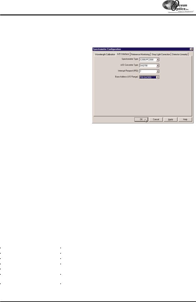
A/D Converters: DAQ-700
Spectrometer Configuration Dialog Box
Now that OOIBase32 is running, you need to configure your system. Select Spectrometer | Configure from the menu. Go through each page in the Spectrometer Configuration dialog box to set system parameters. (See the
OOIBase32 Spectrometer Operating Software Manual for details.)
"In the Wavelength Calibration page, the coefficients for each spectrometer channel in your system have already been loaded as part of the spectrometer configuration file. Check the Enabled box for each spectrometer channel in your system.
"In the A/D Interface page, enter the same values as you did in the Configure Hardware dialog box.
"The Detector Linearity page in this dialog box allows you to enter coefficients for an algorthim that corrects for rare occurances of non-linearity of the detector. Contact Ocean Optics for more information.
Save the spectrometer configuration file by choosing Spectrometer | Save Configuration As from the OOIBase32 menu. You can rename the
file or use the default file name ([your serial number].spec). You will then be asked if you would like to make this file the default spectrometer configuration file. Choose Yes. The next time you run OOIBase32, the software will use the file as the standard for your spectrometer configuration. When you exit OOIBase32, any changes to the configuration file will be automatically saved to the default file.
OOIBase32 Settings Dialog Box
At this point, it is a good idea to configure several OOIBase32 operation parameters. Choose Edit | Settings from the menu to open the OOIBase32 Settings dialog box. Go through each page of this dialog box to select options for saving, opening, and printing data; to choose waveform sound files for various program events; to configure default setting files; and to select other important options such as storing and copying data and choosing warning messages. (See the OOIBase32 Spectrometer Operating Software Manual for details.)
Configure Data Acquisition Dialog Box
Finally, select Spectrum | Configure Data Acquisition from the menu to set your data acquisition parameters in the Configure Data Acquisition dialog box. The Basic page allows you to set the integration time and choose averaging and boxcar smoothing values. The External Trigger page allows you to specify the external trigger mode. The Strobe page allows you to control external strobe events with the spectrometer. (See the OOIBase32 Spectrometer Operating Software Manual for details.)
|
Specifications |
|
|
|
|
Type: |
PCMCIA Type II |
|
Resolution: |
12-bit |
|
Sampling frequency: |
100 kHz (maximum) |
|
Channels: |
16-channel single-ended; 8-channel differential |
|
Interface cable: |
50-pin connector to A/D card; 25-pin connector to spectrometer |
|
Multiple-channel capability: |
supports up to 4 spectrometer channels (number of supportable channels is |
|
function of electrical current limitations) |
||
|
- 30 -
Loading...