

NorthStar Navigation GM1708 961X, GM1708 961XD User Manual
961X/XD
GPS C
HART
AVIGATOR
N
I
Northstar Technologies
30 Sudbury Road
Acton, Massachusetts 01720
NSTALLATION
Revision A
Part Number G M1708
M
ANUAL
www.northstarcmc.com
Service: 978/897-0770
Sales: 978/897-6600


Limited warranty policy
Northstar Technologies warrants the Northstar 961 to be free from defects
in materials and workmanship for a period of two (2) years. This warranty
applies to the original purchaser and to any subsequent owner during the
warranty period, which begins on the date of shipment of the unit, F.O.B.
Acton, Massachusetts, to an authorized Northstar dealer.
Systems may not be returned to Northstar without a Returned Materials
Authorization (RMA) number. Call the Northstar dealer or Northstar for
instructions.
During the unit’s warranty period, Northstar will repair or replace, at its
option, any part of the unit it finds to be defective due to faulty material(s) or workmanship. All such repairs and/or replacements will be
promptly performed by Northstar free-of-charge to the owner, excluding
freight costs incurred in shipping to the factory. Return shipments from
Northstar to points within the United States are made via ground transportation, freight prepaid. Special shipping charges (overnight, two-day,
and so on) are the responsibility of the owner.
To be covered by this warranty, the Northstar equipment must have been
in normal use. This warranty does not apply to units with defects caused
by improper installation, physical damage, abuse, tampering, lightning or
other abnormal electrical discharge, or to units with defaced or altered
serial numbers, or to units repaired by unauthorized persons or repaired
in a manner that violates Northstar’s recommended service procedures.
All repairs and/or replacements made under this warranty must be performed at Northstar’s facilities in Acton, Massachusetts. Performance of
warranty work elsewhere will not be authorized, and Northstar will not
pay for any charges for such work. Northstar will not be responsible for
payment of any charges imposed by a Northstar dealer or other party for
services requested by and/or performed for a unit’s owner in connection
with this warranty. Such services might include removal of the unit from
a vessel, inspection, packaging, handling, reinstallation, and the like.
Northstar Technologies assumes no responsibility for any consequential
losses of any nature with respect to any of its products or services sold,
rendered, or delivered. The foregoing is the only warranty expressed or
implied. No other warranty exists.


Contents
SECTION ONE - Introduction. . . . . . . . . . . . . . . . . . . . . . . . . . . . . . . . . . . . . . . . . . . . . . . . 1
Welcome . . . . . . . . . . . . . . . . . . . . . . . . . . . . . . . . . . . . . . . . . . . . . . . . . . . . . . . . . . . . . . . . . . . . . . . . .1
Who should read this manual . . . . . . . . . . . . . . . . . . . . . . . . . . . . . . . . . . . . . . . . . . . . . . . . . . . . . . 1
Scope of this manual . . . . . . . . . . . . . . . . . . . . . . . . . . . . . . . . . . . . . . . . . . . . . . . . . . . . . . . . . . . . . . 1
Getting technical support . . . . . . . . . . . . . . . . . . . . . . . . . . . . . . . . . . . . . . . . . . . . . . . . . . . . . . . . . .2
Servicing the unit . . . . . . . . . . . . . . . . . . . . . . . . . . . . . . . . . . . . . . . . . . . . . . . . . . . . . . . . . . . . . . . . . 3
Returning a unit for service . . . . . . . . . . . . . . . . . . . . . . . . . . . . . . . . . . . . . . . . . . . . . . . . . . . . . . . . . 3
Ordering information . . . . . . . . . . . . . . . . . . . . . . . . . . . . . . . . . . . . . . . . . . . . . . . . . . . . . . . . . . . . . . 4
SECTION TWO - Installation . . . . . . . . . . . . . . . . . . . . . . . . . . . . . . . . . . . . . . . . . . . . . . . . 5
Safety considerations . . . . . . . . . . . . . . . . . . . . . . . . . . . . . . . . . . . . . . . . . . . . . . . . . . . . . . . . . . . . . . 5
System overview . . . . . . . . . . . . . . . . . . . . . . . . . . . . . . . . . . . . . . . . . . . . . . . . . . . . . . . . . . . . . . . . . .6
Installation considerations . . . . . . . . . . . . . . . . . . . . . . . . . . . . . . . . . . . . . . . . . . . . . . . . . . . . . . . . . . 6
Choosing a system location . . . . . . . . . . . . . . . . . . . . . . . . . . . . . . . . . . . . . . . . . . . . . . . . . . . . . . . . 9
Wiring the 961 . . . . . . . . . . . . . . . . . . . . . . . . . . . . . . . . . . . . . . . . . . . . . . . . . . . . . . . . . . . . . . . . . . .12
Installing the antenna . . . . . . . . . . . . . . . . . . . . . . . . . . . . . . . . . . . . . . . . . . . . . . . . . . . . . . . . . . . .14
Turning the unit on and off . . . . . . . . . . . . . . . . . . . . . . . . . . . . . . . . . . . . . . . . . . . . . . . . . . . . . . .26
Testing and troubleshooting the 961 . . . . . . . . . . . . . . . . . . . . . . . . . . . . . . . . . . . . . . . . . . . . . . .32
SECTION THREE - Interfacing . . . . . . . . . . . . . . . . . . . . . . . . . . . . . . . . . . . . . . . . . . . . . 45
Interfacing the unit . . . . . . . . . . . . . . . . . . . . . . . . . . . . . . . . . . . . . . . . . . . . . . . . . . . . . . . . . . . . . . .45
Configuring the NMEA output ports . . . . . . . . . . . . . . . . . . . . . . . . . . . . . . . . . . . . . . . . . . . . . . . .46
Setting the auxiliary port . . . . . . . . . . . . . . . . . . . . . . . . . . . . . . . . . . . . . . . . . . . . . . . . . . . . . . . . . .53
Setting PPNM . . . . . . . . . . . . . . . . . . . . . . . . . . . . . . . . . . . . . . . . . . . . . . . . . . . . . . . . . . . . . . . . . . . .55
Using VGA output . . . . . . . . . . . . . . . . . . . . . . . . . . . . . . . . . . . . . . . . . . . . . . . . . . . . . . . . . . . . . . . .56
SECTION FOUR - Service/Maintenance . . . . . . . . . . . . . . . . . . . . . . . . . . . . . . . . . . . . 57
Service functions . . . . . . . . . . . . . . . . . . . . . . . . . . . . . . . . . . . . . . . . . . . . . . . . . . . . . . . . . . . . . . . . .57
Maintenance functions . . . . . . . . . . . . . . . . . . . . . . . . . . . . . . . . . . . . . . . . . . . . . . . . . . . . . . . . . . . .68
APPENDIX A - Technical Specifications . . . . . . . . . . . . . . . . . . . . . . . . . . . . . . . . . . . . 69
Northstar 961 . . . . . . . . . . . . . . . . . . . . . . . . . . . . . . . . . . . . . . . . . . . . . . . . . . . . . . . . . . . . . . . . . . . .69
Physical features . . . . . . . . . . . . . . . . . . . . . . . . . . . . . . . . . . . . . . . . . . . . . . . . . . . . . . . . . . . . . . . . .70
Internal beacon receiver specifications (961XD) . . . . . . . . . . . . . . . . . . . . . . . . . . . . . . . . . . . . . .71
AN150 Active GPS Antenna . . . . . . . . . . . . . . . . . . . . . . . . . . . . . . . . . . . . . . . . . . . . . . . . . . . . . . .71
8410 Antenna Coupling Unit . . . . . . . . . . . . . . . . . . . . . . . . . . . . . . . . . . . . . . . . . . . . . . . . . . . . . .72
AN205-P GPS/DGPS antenna . . . . . . . . . . . . . . . . . . . . . . . . . . . . . . . . . . . . . . . . . . . . . . . . . . . . . .72
961 INSTALLATION MANUAL Revision A Page i

Page ii 961 INSTALLATION MANUAL Revision A

Figures
Figure 1: 961 control head yoke-mount dimensions (side) . . . . . . . . . . . . . . . . . . . . . . . . . . . . . . . . . . .10
Figure 2: 961 control head yoke-mount dimensions (front) . . . . . . . . . . . . . . . . . . . . . . . . . . . . . . . . . .10
Figure 3: 961 control head flush-mount drilling dimensions . . . . . . . . . . . . . . . . . . . . . . . . . . . . . . . . .11
Figure 4: Processor connectors (back of unit) . . . . . . . . . . . . . . . . . . . . . . . . . . . . . . . . . . . . . . . . . . . . . . .13
Figure 5: Separation distances between antennas . . . . . . . . . . . . . . . . . . . . . . . . . . . . . . . . . . . . . . . . . . .15
Figure 6: GPS-only antenna (AN150) . . . . . . . . . . . . . . . . . . . . . . . . . . . . . . . . . . . . . . . . . . . . . . . . . . . . . .17
Figure 7: Stripping the coax cable jacket . . . . . . . . . . . . . . . . . . . . . . . . . . . . . . . . . . . . . . . . . . . . . . . . . . .18
Figure 8: Flared cable braid . . . . . . . . . . . . . . . . . . . . . . . . . . . . . . . . . . . . . . . . . . . . . . . . . . . . . . . . . . . . . .18
Figure 9: Completed BNC connector . . . . . . . . . . . . . . . . . . . . . . . . . . . . . . . . . . . . . . . . . . . . . . . . . . . . . .19
Figure 10: Combo GPS/DGPS antenna (AN205-P) . . . . . . . . . . . . . . . . . . . . . . . . . . . . . . . . . . . . . . . . . . .19
Figure 11: Correct AN205-P (combo antenna) splitter wiring . . . . . . . . . . . . . . . . . . . . . . . . . . . . . . . . .20
Figure 12: Stripping the coax cable jacket . . . . . . . . . . . . . . . . . . . . . . . . . . . . . . . . . . . . . . . . . . . . . . . . . .21
Figure 13: Flared cable braid . . . . . . . . . . . . . . . . . . . . . . . . . . . . . . . . . . . . . . . . . . . . . . . . . . . . . . . . . . . . .21
Figure 14: Completed TNC connector . . . . . . . . . . . . . . . . . . . . . . . . . . . . . . . . . . . . . . . . . . . . . . . . . . . . .21
Figure 15: ACU assembly . . . . . . . . . . . . . . . . . . . . . . . . . . . . . . . . . . . . . . . . . . . . . . . . . . . . . . . . . . . . . . . .23
Figure 16: Correct AN150 and 8410 wiring . . . . . . . . . . . . . . . . . . . . . . . . . . . . . . . . . . . . . . . . . . . . . . . .24
Figure 17: PL-259 (UHF) connector . . . . . . . . . . . . . . . . . . . . . . . . . . . . . . . . . . . . . . . . . . . . . . . . . . . . . . .26
Figure 18: Initial startup screen . . . . . . . . . . . . . . . . . . . . . . . . . . . . . . . . . . . . . . . . . . . . . . . . . . . . . . . . . . .27
Figure 19: System test screen . . . . . . . . . . . . . . . . . . . . . . . . . . . . . . . . . . . . . . . . . . . . . . . . . . . . . . . . . . . . .27
Figure 20: Owner’s message screen . . . . . . . . . . . . . . . . . . . . . . . . . . . . . . . . . . . . . . . . . . . . . . . . . . . . . . .28
Figure 21: Advisory message . . . . . . . . . . . . . . . . . . . . . . . . . . . . . . . . . . . . . . . . . . . . . . . . . . . . . . . . . . . . .29
Figure 22: GPS satellite status screen . . . . . . . . . . . . . . . . . . . . . . . . . . . . . . . . . . . . . . . . . . . . . . . . . . . . . .30
Figure 23: Interface cabling wiring screen . . . . . . . . . . . . . . . . . . . . . . . . . . . . . . . . . . . . . . . . . . . . . . . . .45
Figure 24: Port 1 output setup screen . . . . . . . . . . . . . . . . . . . . . . . . . . . . . . . . . . . . . . . . . . . . . . . . . . . . .47
961 INSTALLATION MANUAL Revision A Page iii

Figure 25: Port 1 output setup (sentences) screen . . . . . . . . . . . . . . . . . . . . . . . . . . . . . . . . . . . . . . . . . . .49
Figure 26: Port 1 output setup screen . . . . . . . . . . . . . . . . . . . . . . . . . . . . . . . . . . . . . . . . . . . . . . . . . . . . .51
Figure 27: Auxiliary port setup screen . . . . . . . . . . . . . . . . . . . . . . . . . . . . . . . . . . . . . . . . . . . . . . . . . . . . .54
Figure 28: PPNM output setup screen . . . . . . . . . . . . . . . . . . . . . . . . . . . . . . . . . . . . . . . . . . . . . . . . . . . . .55
Figure 29: Product information screen . . . . . . . . . . . . . . . . . . . . . . . . . . . . . . . . . . . . . . . . . . . . . . . . . . . .57
Figure 30: Receiver information screen . . . . . . . . . . . . . . . . . . . . . . . . . . . . . . . . . . . . . . . . . . . . . . . . . . . .59
Figure 31: GPS satellite status screen . . . . . . . . . . . . . . . . . . . . . . . . . . . . . . . . . . . . . . . . . . . . . . . . . . . . . .62
Figure 32: Database function screen . . . . . . . . . . . . . . . . . . . . . . . . . . . . . . . . . . . . . . . . . . . . . . . . . . . . . .64
Figure 33: Select database to save dialog box . . . . . . . . . . . . . . . . . . . . . . . . . . . . . . . . . . . . . . . . . . . . . . .65
Figure 34: Select database to restore dialog box . . . . . . . . . . . . . . . . . . . . . . . . . . . . . . . . . . . . . . . . . . . .66
Figure 35: Select a restored database to undo dialog box . . . . . . . . . . . . . . . . . . . . . . . . . . . . . . . . . . . .67
Figure 36: Save log data dialog box . . . . . . . . . . . . . . . . . . . . . . . . . . . . . . . . . . . . . . . . . . . . . . . . . . . . . . .68
Page iv 961 INSTALLATION MANUAL Revision A

Tables
Table 1: Contacting Northstar . . . . . . . . . . . . . . . . . . . . . . . . . . . . . . . . . . . . . . . . . . . . . . . . . . . . . . . . . . . . . 2
Table 2: Troubleshooting the installation . . . . . . . . . . . . . . . . . . . . . . . . . . . . . . . . . . . . . . . . . . . . . . . . . 32
Table 3: Troubleshooting the GPS/DGPS antenna installation . . . . . . . . . . . . . . . . . . . . . . . . . . . . . . . . 39
Table 4: Troubleshooting the radar interface . . . . . . . . . . . . . . . . . . . . . . . . . . . . . . . . . . . . . . . . . . . . . . . 42
Table 5: Interface cable wiring . . . . . . . . . . . . . . . . . . . . . . . . . . . . . . . . . . . . . . . . . . . . . . . . . . . . . . . . . . 46
Table 6: Port setup options. . . . . . . . . . . . . . . . . . . . . . . . . . . . . . . . . . . . . . . . . . . . . . . . . . . . . . . . . . . . . . . 47
Table 7: NMEA 0183 sentence identifiers . . . . . . . . . . . . . . . . . . . . . . . . . . . . . . . . . . . . . . . . . . . . . . . . . . 49
Table 8: Aux port setup parameters . . . . . . . . . . . . . . . . . . . . . . . . . . . . . . . . . . . . . . . . . . . . . . . . . . . . . . . 54
Table 9: PPNM output setup parameters . . . . . . . . . . . . . . . . . . . . . . . . . . . . . . . . . . . . . . . . . . . . . . . . . . . 56
961 INSTALLATION MANUAL Revision A Page v

Page vi 961 INSTALLATION MANUAL Revision A
Welcome
SECTION ONE - Introduction
SECTION ONE - Introduction
he Northstar 961 Installation Manual describes how to install the entire
T
961 system (control head, processor, and antenna). It describes the physical, mechanical, and electrical characteristics of the unit, as well as how to
select the right location, and mount and wire the system. This manual
also describes how to interface, troubleshoot, and maintain the Northstar
961 GPS chart navigator. For complete details on operating the unit, see
the Northstar 961 Operations and Reference Manual (part number
GM1700).
The terms “unit” and “961” are used throughout this manual to refer to
the 961 GPS chart navigator. The 961X is differential-ready so you can
interface it to an external differential receiver. The 961XD has a built-in
differential receiver. Unless specifically indicated, all information in this
manual refers to both the X (non-differential) and XD (differential) ver-
sions of the unit.
Who should read this manual
The Northstar 961 Installation Manual is intended for marine technicians
who are configuring and installing the 961 GPS chart navigator.
To obtain the best performance from your 961, Northstar
strongly recommends that you have an authorized Northstar
dealer perform the installation. Proper installation of the Northstar 961 is of utmost importance to accurately receive and
effectively use GPS signals under a variety of weather conditions.
Scope of this manual
In this manual, you’ll find information on the following procedures:
choosing a location
•
mounting and wiring the unit
•
installing the antenna
•
testing the unit
•
interfacing the 961 to other instruments
•
CAUTION!
troubleshooting the unit
•
configuring the NMEA output ports
•
setting the auxiliary port
•
961 INSTALLATION MANUAL Revision A Page 1

SECTION ONE - Introduction
setting pulses per nautical mile (PPNM)
•
service functions
•
maintaining the unit
•
installing software updates and saving and restoring the database
•
The unit’s technical specifications can be found in Appendix A at the back
of this manual.
The rest of this section explains how to obtain technical support and how
to return a unit for service.
Getting technical support
After you’ve followed the instructions in this installation guide, if you
require additional technical support or have any other service-related
questions, you can contact either your dealer or the Northstar Service
Department. Northstar’s Service Department can be reached by email, fax,
U.S. mail, or phone as described in the table below. Whether you send an
email or fax, or write or phone, please have the unit’s serial number available, and be as complete and accurate as possible when describing the
problem so that a service technician can research the problem and pro-
You can email the Service Department directly
from Northstar’s website.
The address is
www.northstarcmc.com.
From here, you also can
access additional technical information under
either the Manuals or
Support links.
vide the quickest possible response.
Northstar’s Service Department is available between 9:00 AM and 5:00
PM Eastern Time, Monday through Friday, excluding major holidays.
Table 1: Contacting Northstar
Email:
Service: service@northstarcmc.com
Sales: sales@northstarcmc.com
Fax:
Service: 978/897-1595
Sales: 978/897-7241
Telephone:
Main number: 978/897-6600 or 800/628-4487
Sales: 978/897-0770
Service: 978/897-6600
Hearing from you
U.S. mail:
30 Sudbury Road
Acton, MA 01720
Website:
www.northstarcmc.com (you can send email to
Northstar directly from this site)
Your feedback is important and helps ensure that this manual is a valuable resource for all marine technicians. Send your questions, comments,
or suggestions about this manual to:
Page 2 961 INSTALLATION MANUAL Revision A
Servicing the unit
Repair of the unit is performed only at the Northstar factory. Service
includes a complete hardware and software check-out.
Field repairs are not authorized and will void the warranty!
For a system under warranty, shipping charges to the factory are the only
cost for factory repair. Repaired units will be returned via prepaid economy ground freight (units returned overseas are chargeable).
Units and accessories returned for warranty repair that are determined to
be without fault are subject to a handling charge.
Returning a unit for service
Before returning the unit
to the Northstar factory,
to prevent delays it is
critical that you first
obtain a Return Materials Authorization (RMA)
number from the Northstar Service Department.
If you purchased your
unit through a dealer,
call the dealer and provide your serial number
so they can get you an
RMA number.
Shipments without a
proper RMA number will
not be accepted!
The unit is covered by a two-year hardware-only warranty, which, in
summary, states that if the unit is returned to the factory by the owner or
dealer during the warranty period, Northstar will repair or replace, free of
charge, any part found to be defective due to faulty materials or workmanship, if the system has been properly installed and hasn’t been
abused. See the Limited Warranty Policy at the front of this manual for
further details. The only cost to the owner will be the one-way shipping
charges and any associated charges that may be imposed by the dealer. If
you have overnight or second-day shipping requirements, before shipping the unit, please call the factory for turnaround time, freight charges,
and payment arrangements.
You may want to ensure that the user has backed-up any of
their waypoints and routes before returning the unit for repair;
see “Saving and restoring databases and system logs” beginning on page 63 for information on backing up waypoints and
routes.
SECTION ONE - Introduction
service@northstarcmc.com
NOTE:
CAUTION!
The unit should be shipped only in a properly designed carton with packing material. Shipments to the Northstar factory should be made to the
following address:
Northstar Technologies
Service Department
30 Sudbury Road
Acton, MA 01720 USA
961 INSTALLATION MANUAL Revision A Page 3

SECTION ONE - Introduction
Ordering information
To order spare parts or replacement/missing parts, call the Northstar Sales
Department at 978-897-0770.
Page 4 961 INSTALLATION MANUAL Revision A
SECTION TWO - Installation
his chapter includes all the information needed to install the 961. It
T
begins with a review of the system components and then provides information on basic installation and powering on the unit. The rest of the
chapter describes how to wire the unit, install the antenna, and troubleshoot. Proper installation of the Northstar 961 is of utmost importance to
accurately receive and effectively use GPS signals under a wide variety of
weather conditions.
Safety considerations
SECTION TWO - Installation
WARNING!
Be sure to turn the power off at the main switchboard
before starting the installation. Further, it is highly
recommended that you post a sign by this switch telling others to keep power off while you’re performing
the installation. If power is left on or turned on during
the installation, fire, electrical shock, or other serious
injury may occur.
WARNING!
Be sure to use the proper fuse. Using the incorrect
fuse can result in fire or damage to the equipment.
CAUTION!
WARNING!
Be sure that the voltage of the power supply is
compatible with the unit’s voltage rating, which
can be found on the label at the rear of the unit.
Connecting to the wrong power supply can
result in fire or damage to the equipment.
Be sure to ground the equipment in order to prevent electrical shock or mutual interference.
CAUTION!
Make sure that the 961 does not interfere with
any of the on-board systems. Check all other
systems to ensure that their performance
doesn’t degrade when the unit is turned on.
CAUTION!
The 961 processor can only be mounted horizontally
due to its rubber vibration mounts.
961 INSTALLATION MANUAL Revision A Page 5
If you must cut the processor’s 10-foot power
cord shorter, be sure to keep the external fuse
intact. If the power cable must be longer than 10
feet, use a heavier gauge wire for those applications and be sure to use an external fuse.

SECTION TWO - Installation
System overview
The unit is shipped ready to install and operate.
It is recommended that you follow the steps below:
1. Check the shipping carton for any damage, and immediately report
any damage to the carrier. Save all packing material in case you have
to return the unit to the factory for repair or evaluation. For return
procedures, see “Returning a unit for service” beginning on page 3.
2. Unpack the cartons. Compare the 961 Packing List (P/N GM1703),
included in the 961’s packaging against the contents in those cartons
and with what you ordered.
3. Make sure you have the tools necessary to complete the installation.
4. After reviewing the components, next, review the components of a
proper installation. For details, see “Installation considerations”
beginning on page 6.
5. Choose the best location to mount the control head(s) and processor.
For suggestions and further information, see “Choosing a system
location” beginning on page 9.
6. Choose the best location to mount the antenna. For suggestions and
further information, see “Installing the antenna” beginning on
page 14.
7. Review the section on wiring the system. For details, see “Wiring the
961” beginning on page 12.
8. Install the control head(s), processor, and antenna. (You may want to
temporally install the antenna, then try operating the 961 to ensure
the antenna location works well before permanently installing the
antenna.)
9. Turn on the unit. For details, see “Turning the unit on and off” beginning on page 26.
10.To ensure that the system is installed correctly and running properly,
perform a functional test. For details, see “Testing and troubleshooting the 961” beginning on page 32.
11.If desired, interface the NMEA output ports; for details, see “Configuring the NMEA output ports” beginning on page 46. If desired,
interface the auxiliary port, see “Setting the auxiliary port” beginning
on page 53.
Installation considerations
CAUTION!
The following basic installation considerations aren’t a substitute for all the details in SECTION TWO. To ensure that you
meet all critical installation parameters, be sure to read and follow everything in this section.
Page 6 961 INSTALLATION MANUAL Revision A

SECTION TWO - Installation
Ensuring a proper
961 installation
To ensure a proper installation, it is highly recommended that you perform all of the following activities before starting the installation:
preview/survey the vessel’s layout and existing equipment
•
review all the installation materials
•
review all the installation requirements, including:
•
- the physical requirements (spacing, location with regard to other
equipment, etc.)
- the electrical and electronic requirements (interference between
other pieces of equipment, power requirements, etc.)
Although the unit itself is very straightforward and easy-to-understand, it
has a few basic requirements that must be met before safe and proper
operation can be assured. The major parts of the rest of this section
address several topics regarding the minimum installation requirements
for the unit to:
minimize electrical wiring hazards
•
be mounted correctly
•
accurately receive GPS and DGPS signals
•
navigate safely
•
Avoiding
shortcuts
Using the GPS
antenna (AN150)
The majority of installation problems are caused by shortcuts taken with
system cables. When installing your 961, be sure to:
assemble the connectors carefully
•
•
don’t make sharp bends in the cables
leave service and drip loops
•
•
tie-wrap all cables to keep them secure
if cables are lengthened, seal all wiring splices
•
The “active” GPS antenna is best mounted in the clear, and low on the
vessel to avoid extra motion from pitching and rolling. It should be
mounted lower than directional high-power transmitting antennas such
as radar or satcom. The length of coaxial cable to the “active” AN150
antenna (supplied with the unit) must be a minimum of 20 feet, but not
more than 100 feet. Coil up any unused length of cable;
less than 20 feet!
and that the cable itself is not subject to any tight bends.
For complete details about installing the AN150, see “Installing the
antenna” beginning on page 14.
Be sure that all cable connectors are securely fastened,
do not cut it to
961 INSTALLATION MANUAL Revision A Page 7

SECTION TWO - Installation
Using DGPS with
an AN150 and
8410 ACU
Using the DGPS
antenna
(AN205-P)
Bench-testing the
961
If the unit is equipped with a differential receiver (and you’re using the
AN150 GPS antenna, not the AN205-P GPS/DGPS combo antenna), this
receiver must be connected to a Northstar 8410 differential Antenna
Coupling Unit (ACU). The ACU’s four-foot whip antenna should be
mounted as high as conveniently possible (but not at the highest point)
and as far away as possible from other antennas. The ACU can be
mounted on a standard marine antenna mount (1" diameter, 14 threads
per inch).
For complete details about installing the AN150/8410 ACU, see “Installing an 8410 ACU (for use with the AN150 only)” beginning on page 22.
For complete details about installing the AN205-P, see “Installing the
antenna” beginning on page 14.
It is recommended that you bench-test the unit before installing it on the
vessel. Bench testing ensures that the equipment is fully operational, and
allows the GPS receiver to collect its almanac and ephemeris data for the
installed location, which results in less on-board installation time.
Page 8 961 INSTALLATION MANUAL Revision A

Choosing a system location
The 961 consists of two major parts—a processor and a control head. The
961 supports two fully functional control heads (the second head is
optional). The 961 system comprises the processor and control head, GPS
receiver, optional differential receiver, controls, and the specially-coated
display screen.
SECTION TWO - Installation
Mounting the
control head
You can either yoke- or flush-mount the control head: Use the
yoke-mount kit as a framework for holding the control head, or
flush-mount the control head directly onto a flat surface of your choice.
Using the Northstar-supplied yoke mounting kit usually provides a
quicker and less expensive installation than a flush-mount installation.
Regardless of the type of mount, here are a few helpful hints about where
to mount the control head. Choose the mounting location carefully—before any drilling or cutting takes place. Choose a location that:
is convenient, accessible, and within comfortable reach
•
•
gives you easy access to the function keys
is where you can clearly see the display screen from your normal
•
vantage point when navigating
for best display contrast, is viewed from below, looking up at the
•
display screen
provides a reasonably direct path for running the required electrical
•
cables
has minimal glare from windows or other bright objects (even
•
though the unit has a high-contrast, anti-reflective LCD screen
that’s specially coated and readable in direct sunlight, you’ll want to
make the screen as visible as possible)
if flush-mounting the head, make sure you choose an area that’s
•
well-ventilated; poor ventilation may cause overheating, resulting
in potential backlighting problems
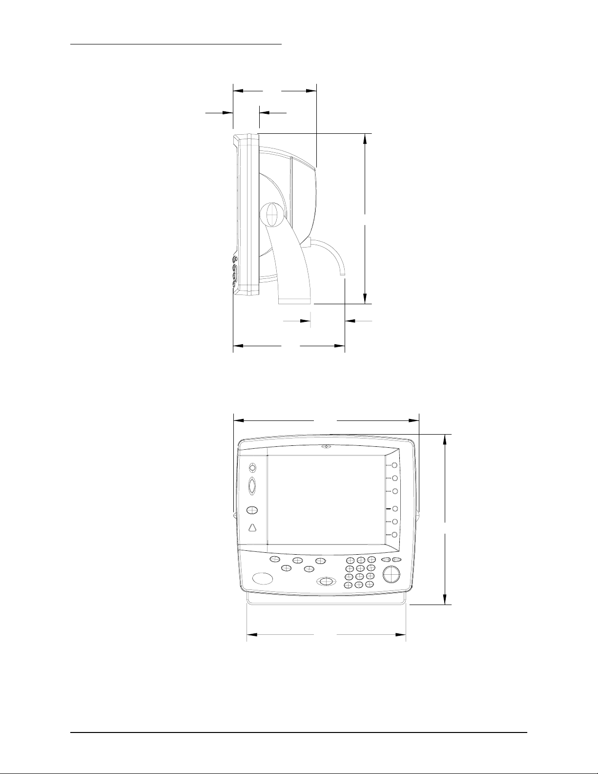
Yoke mounting
For yoke mounts, leave ample room—usually two inches—all around the
sides and top to avoid crowding the unit. Also allow a clearance of at least
2½ inches in the rear just for the cables and connectors. For the recommended yoke-mount installation dimensions, see Figure 1, and Figure 2.
Before drilling holes, rotate the unit to the desired angle to ensure proper
clearance for cables and operation of the unit.
961 INSTALLATION MANUAL Revision A Page 9
SECTION TWO - Installation
6.1
1.9
12.4
2.5
8.2
Figure 1: 961 control head yoke-mount dimensions (side)
13.5
12.4
11.6
Figure 2: 961 control head yoke-mount dimensions (front)
Page 10 961 INSTALLATION MANUAL Revision A
SECTION TWO - Installation
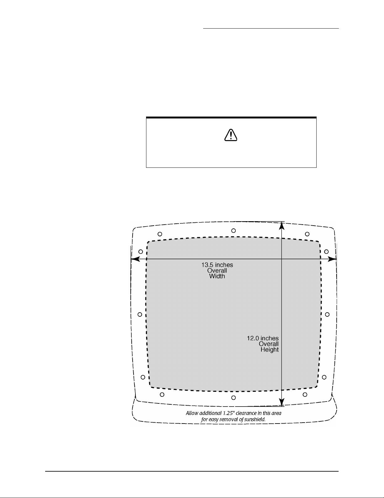
Flush mounting
For flush-mounting the unit, allow at least 2½-inch clearance at the rear
for cables and connectors.
For the recommended flush mounting drilling dimensions, see Figure 3
below. For the full-size version of the flush-mount installation measurements and instructions, refer to the full-size flush-mount template (P/N
GT1600) included in the 961 shipping carton.
CAUTION!
When flush-mounting, be sure to mount the unit on a flat surface. Mounting on a curved surface can distort or break the
plastic and cause a breech in the waterproof seal.
Make sure you provide for adequate ventilation, especially if the unit is
installed in a closed area that’s usually poorly ventilated. Poor ventilation
will cause the head to overheat, which in turn may cause the display
screen to darken.
Figure 3: 961 control head flush-mount drilling dimensions
961 INSTALLATION MANUAL Revision A Page 11

SECTION TWO - Installation
Installing the
processor
For the processor installation measurements and instructions, refer to the
full-size flush-mount templates, “961 Processor Mounting Template, top
view” (P/N GM1700) and the “961 Processor Mounting Template, front
view” (P/N GM 1701) included in the 961 shipping carton.
To properly install the processor, you must first install the mounting
bracket to the surface of the vessel, then attach the processor to the
bracket.
Processor installation tips
check the dimensions of the processor mounting bracket; these
•
dimension are provided on the enclosed template.
follow the recommended clearance around the sides and front of
•
the unit.
install the processor in a spacious, well-ventilated area to minimize
•
heat-related problems.
mount the processor on a hard, solid, vibration-free surface of at
•
least 3/4-inch thickness. If the surface is carpeted, make sure that
the carpet doesn’t block the bottom ventilation holes or interfere
with the mounting plate vibration/shock mounts.
Wiring the 961
10-foot power cable goes to 10-36 Volts DC.
•
The majority of installation problems are caused by shortcuts taken with
system cables. When installing the unit, be sure that you:
assemble connectors carefully
•
don’t make sharp bends
•
leave service and drip loops
•
tie-wrap all cables to keep them secure
•
if cables are lengthened, seal all wiring splices
•
The 961 operates on DC power from a 10-volt minimum to a 40-volt
maximum connected by at least 16-gauge wire. The 10-foot power cable
supplied with your 961 should be long enough for most installations, but
if you must lengthen the power cable, you can extend it to a maximum of
25 feet without adversely affecting the 961’s operation. For lengths up to
15 feet, the power connections to the battery must use 16-gauge wire or
heavier. For lengths of 15 feet or more, use 14-gauge wire or heavier.
Regardless of the length of the cable, you should use a 20-amp external
fuse as an added safety precaution ((the 961 has an external fuse in its
standard 10-foot power cable). The external fuse protects the vessel wir-
Page 12 961 INSTALLATION MANUAL Revision A

SECTION TWO - Installation
ing and prevents electrical fires. The power wiring should be connected
directly to the battery when possible for optimum noise immunity.
CAUTION!
Ensure that fuse or circuit-breaker protection is provided at the
power source. If you must cut the processor’s 10-foot power
cable shorter, be sure to keep the external fuse intact. If the
power cable must be longer than 10 feet, use a heavier gauge
wire for those applications, and be sure to use an external fuse.
Electrical power
requirements
Wiring the
system
The 961 is a negative-ground system. After the processor has been
installed—but before you turn the 961 on—verify that the wires in the
10-foot power cable are connected as follows:
Red — positive (+) 10 to 40 Volts DC (VDC)
•
•
Black — negative (–)
The back of the processor, with all the proper wiring and connections, is
shown in “Figure 4: Processor connectors (back of unit)” below.
Figure 4: Processor connectors (back of unit)
961 INSTALLATION MANUAL Revision A Page 13

SECTION TWO - Installation
Connectors
Power connector (3-wire)
•
TNC connector (control head #1)
•
TNC connector (control head #2)
•
I/O #1 interface connector (18-wire)
•
I/O #2 interface connector (18-wire)
•
GPS antenna connector (BNC)
•
DGPS antenna connector (UHF)
•
PC connectors (variable)
•
VGA
•
Installing the antenna
Choosing an
antenna
Choosing an
antenna location
Three antenna choices are available for the 961X or 961XD:
one for reception of GPS-only signals (the standard one-piece
•
“active” AN150 antenna)
one for reception of both GPS and DGPS signals (a two-piece
•
antenna system comprising the standard AN150 GPS antenna and
the 8410 DGPS coupler)
one for reception of both GPS and DG PS signals (optional one-piece
•
AN205-P “combination” antenna)
Choosing the AN150 antenna location
The GPS receiving antenna is a vital link between the unit’s receiver and
the outside world. Aesthetics and easy access should be secondary to providing strong and reliable GPS signals to the unit’s receiver. You should
select a location for the antenna that meets the following requirements:
The antenna should have a reasonably clear view of the horizon,
•
but be no higher than necessary (side-to-side motion of the
antenna caused by rolling of the vessel may degrade the SOG and
COG readings); however, the antenna should be 12 to 18 inches
above the surrounding surfaces to avoid interference.
The antenna must be out of the radiation path of any on-board
•
radar sets or strong magnetic fields.
The antenna must be lower than any INMARSAT communications
•
antenna.
The antenna should be as far as possible from other high-power
•
transmitting antennas.
Watch out for electromagnetic “shading” of antennas from rigging,
•
other vessels, shoreline buildings, and so on. Secure the cable well.
Page 14 961 INSTALLATION MANUAL Revision A
SECTION TWO - Installation
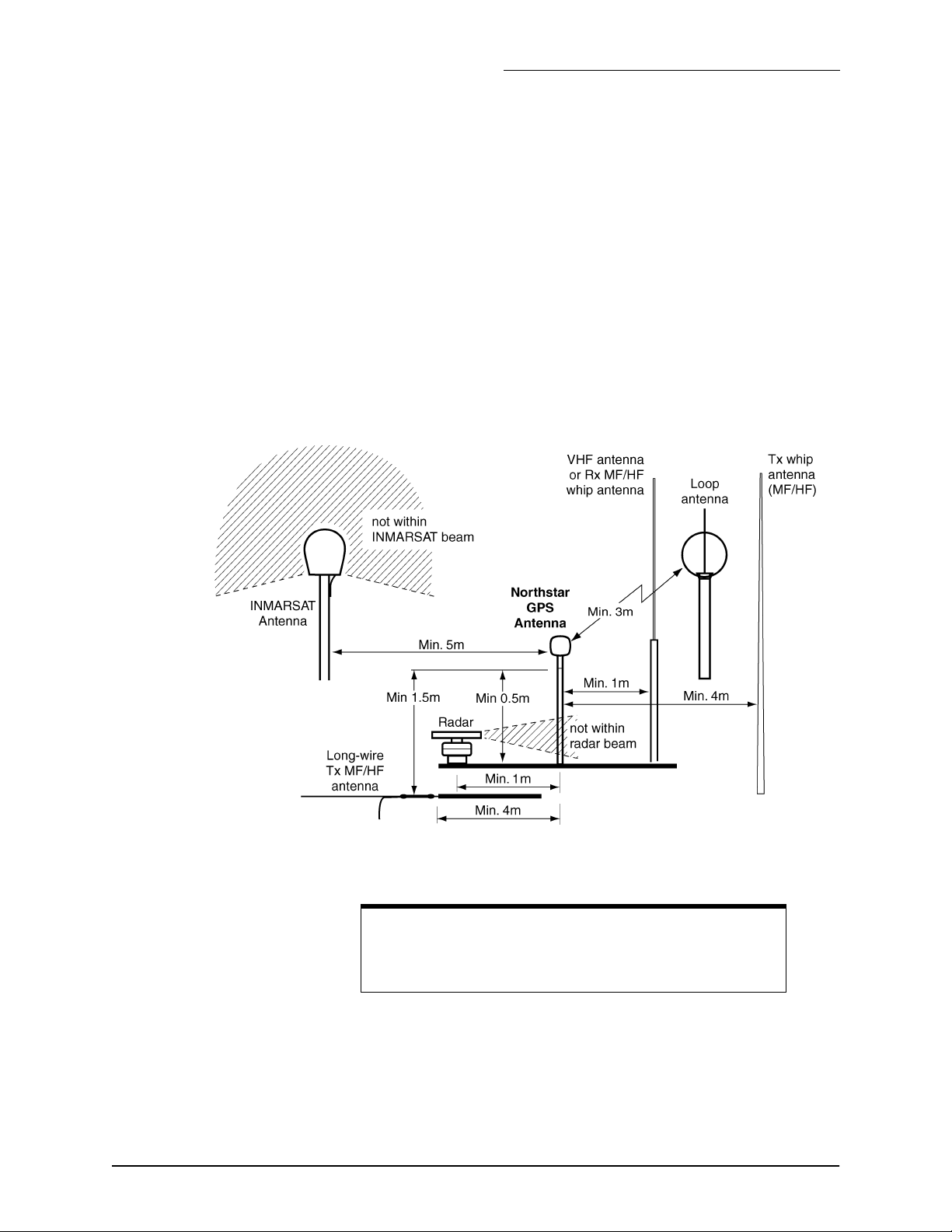
To avoid mutual interferences among different antennas on the vessel,
refer to the drawing of recommended separation distances in Figure 5:
‘Separation distances between antennas,’ below.
Figure 5 shows the minimum recommended distances for the separation
of the GPS antenna from other antennas and physical mounting surfaces.
Under normal circumstances, following these guidelines usually result in
a relatively trouble-free installation.
The installer may want to adjust these distances, however, depending on
the particular equipment and how it is configured. Since each installation
is unique
—
according to the wishes of the customer
—this information
should be used only as a guideline. It is not absolution in determining
the best locations for every possible equipment configuration.
Figure 5: Separation distances between antennas
NOTE:
Be especially careful about the distance between the combo
antenna and any sources of magnetic interference (for example, the INMARSAT antenna).
Choosing the AN205-P combination antenna location
A combination GPS/DGPS antenna is available for applications involving
serious grounding problems (which creates noise issues with the beacon
receiver), where optimum portability is required, or when only a single
961 INSTALLATION MANUAL Revision A Page 15

SECTION TWO - Installation
antenna is desired. The AN205-P doesn’t require any ground and is portable, an advantage when it must be moved from one vessel to another. The
“combo” antenna should be located where it has a clear view of the horizon, but is not the highest point on the vessel. Keep the combo antenna
at least six feet away from objects that can “shade” GPS or differential signals.
If poor GPS Signal-to-Noise Ratio (SNR) readings are obtained after the
unit has been running for several minutes, check that you have the
proper length of cable, and verify the quality of the antenna location and
the quality and proper termination of the connectors. SNR should be as
high as possible. Values of 15 and higher are preferable; anything below
10 could indicate poor reception.
About the
antenna cabling
Installing the
AN150 antenna
Supplied with your 961 system is a 50 foot-length of RG-59 coaxial cable
to use with either the AN150 or the AN205-P. The length of coax cable to
the AN150 antenna must be no less than 50 feet and no more than 100 feet;
to the AN205-P, no less than 20 feet and no more than 50 feet. When
installing antenna cable, don’t bend it tightly in any places, and fasten the
cable along its length to avoid chafing or whipping of any kind. Coil up
any unused length of cable. Secure the cable well (the center conductor is
solid wire), and securely fasten all cable connectors.
Whereas a loran or differential antenna should be mounted high on the
vessel for best performance, the GPS antenna should be mounted as low
as possible and out in the open to avoid “shading” (placement of the
antenna where it is partially obscured by another object from the signals
it must receive). If mounting on top of a tower or mast, understand that
the unit will be affected by the pitch and roll of the vessel. Often the bow
or stern will provide a location where shading is minimized, while serving
to keep the antenna low. Be sure that any directional L-band transmitting
antennas (such as radar or satellite communication antennas) can never
point at the GPS antenna--its internal preamplifier is quickly destroyed by
such radiation.
Page 16 961 INSTALLATION MANUAL Revision A
 Loading...