

Page 1
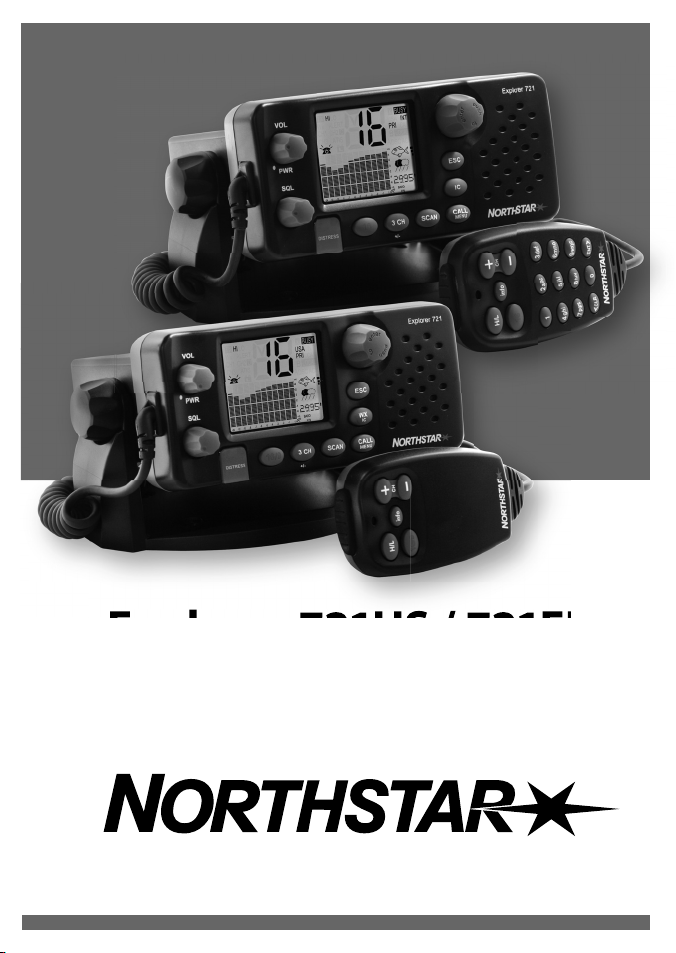
Explorer 721US / 721EU
VHF Marine Radio
Operation and Installation Manual
www.northstarnav.com
Page 2
IMPORTANT SAFETY INFORMATION
Please read carefully before installation and use.
This is the safety alert symbol. It is used to alert you to potential
personal injury hazards, Obey all safety messages that follow this symbol to
avoid possible injury or death.
WARNING indicates a potentially hazardous situation which, if not avoided,
could result in death or serious injury
CAUTION indicates a potentially hazardous situation which, if not avoided, could
result in minor or moderate injury.
CAUTION used without the safety alert symbol indicates a potentially
hazardous situation which, if not avoided, may result in property damage.
DISCLAIMER: It is the owner’s sole
responsibility to install and use the instrument
and transducers in a manner that will not cause
accidents, personal injury or property damage.
The user of this product is solely responsible for
observing safe boating practices.
BRUNSWICK NEW TECHNOLOGIES INC. AND ITS
SUBSIDIARIES AND AFFILIATES DISCLAIM ALL
LIABILIT Y FOR ANY USE OF THIS PRODUCT IN A
WAY THAT MAY CAUSE ACCIDENTS, DAMAGE OR
THAT MAY VIOLATE THE LAW.
Governing Language: This statement,
any instruction manuals, user guides and
other information relating to the product
(Documentation) may be translated to, or
has been translated from, another language
(Translation). In the event of any conf lict
between any Translation of the Documentation,
the English language version of the
Documentation will be the official version of the
Documentation.
This manual represents the Explorer 721
as at the time of printing. Brunswick New
Technologies Inc. and its subsidiaries and
affiliates reserve the right to make changes to
specifications without notice.
Copyright © 2006 Brunswick New Technologies
Inc. Northstar™ is a registered trademark of
Brunswick New Technologies Inc.
FCC Statement
This equipment has been tested and found to comply with the limits for a Class B digital device, pursuant
to Part 15 of the FCC Rules. These limits are designed to provide reasonable protection against harmful
interference in a normal installation. This equipment generates, uses and can radiate radio frequency
energy and, if not installed and used in accordance with the instructions, may cause harmful interference
to radio communications. However, there is no guarantee that interference will not occur in a particular
installation. If this equipment does cause harmful interference to radio or television reception, which
can be determined by turning the equipment off and on, the user is encouraged to try to correct the
interference by one or more of the following measures:
Reorient or relocate the receiving antenna.
Increase the separation between the equipment and receiver.
Connect the equipment into an outlet on a circuit different from that to which the receiver is
connected.
Consult the dealer or an experienced technician for help.
A shielded cable must be used when connecting a peripheral to the serial ports.
2 Northstar Explorer VHF Series: 721US, 721EU Operation and Installation Manual
Page 3

Contents
Secti on 1 - General Infor mation ............................................................................................................... 6
1-1 Features . . . . . . . . . . . . . . . . . . . . . . . . . . . . . . . . . . . . . . . . . . . . . . . . . . . . . . . . . . . . . . . . . . . . . . . . . . 6
1-2 Customize your Northstar VHF Radio . . . . . . . . . . . . . . . . . . . . . . . . . . . . . . . . . . . . . . . . . . . . .6
1-3 How to Display and Navigate Menus . . . . . . . . . . . . . . . . . . . . . . . . . . . . . . . . . . . . . . . . . . . . . .6
1-4 How to Enter or Change Alphanumeric Data . . . . . . . . . . . . . . . . . . . . . . . . . . . . . . . . . . . . . . 7
1-5 LCD Symbols and Meanings . . . . . . . . . . . . . . . . . . . . . . . . . . . . . . . . . . . . . . . . . . . . . . . . . . . . . . 7
1-6 How the Microphone and Optional Handset Work Together . . . . . . . . . . . . . . . . . . . . . . 9
1-7 Basic Operation and Key Functions . . . . . . . . . . . . . . . . . . . . . . . . . . . . . . . . . . . . . . . . . . . . . .10
Secti on 2 - The Radio Menu (MENU)
2-1 The Radio Menu Options (MENU) . . . . . . . . . . . . . . . . . . . . . . . . . . . . . . . . . . . . . . . . . . . . . . .13
2-2 Show Weather, SNR, or Happy Fish on Handset (INFO DATA) . . . . . . . . . . . . . . . . . . . . . 14
2-3 Maintain Your Buddy List (BUDDY LIST) . . . . . . . . . . . . . . . . . . . . . . . . . . . . . . . . . . . . . . . . . . 15
2-4 Local or Distance Sensitivity (LOCAL/DIST) . . . . . . . . . . . . . . . . . . . . . . . . . . . . . . . . . . . . . .16
2-5 Backlighting (BACKLIGHT) and Contrast (CONTRAST) . . . . . . . . . . . . . . . . . . . . . . . . . . . . 16
2-6 GPS Data and Time (GPS/DATA) . . . . . . . . . . . . . . . . . . . . . . . . . . . . . . . . . . . . . . . . . . . . . . . . . . 17
2-7 GPS Simulator (GPS SIM) . . . . . . . . . . . . . . . . . . . . . . . . . . . . . . . . . . . . . . . . . . . . . . . . . . . . . . . . .20
2-8 Reset to Factory Defaults (RESET) . . . . . . . . . . . . . . . . . . . . . . . . . . . . . . . . . . . . . . . . . . . . . . . .20
Secti on 3 - The Radio Setup Me nu (RADIO SETUP) ..................................................................................... 21
3-1 The Radio Setup Menu Options (RADIO SETUP) . . . . . . . . . . . . . . . . . . . . . . . . . . . . . . . . . .21
3-2 Select the Channel Bank (UIC) . . . . . . . . . . . . . . . . . . . . . . . . . . . . . . . . . . . . . . . . . . . . . . . . . . . 21
3-3 Change Channel Names (CH NAME) . . . . . . . . . . . . . . . . . . . . . . . . . . . . . . . . . . . . . . . . . . . . . 21
3-4 Ring and Beep Volume (RING VOL) and (KEY BEEP) . . . . . . . . . . . . . . . . . . . . . . . . . . . . .22
3-5 Internal Speaker Connections (INT SPEAKER) . . . . . . . . . . . . . . . . . . . . . . . . . . . . . . . . . . . .22
3-6 Set the Priority Channel (WATCH MODE) . . . . . . . . . . . . . . . . . . . . . . . . . . . . . . . . . . . . . . . . . 23
3-7 Weather Alert (Wx ALERT) . . . . . . . . . . . . . . . . . . . . . . . . . . . . . . . . . . . . . . . . . . . . . . . . . . . . . . .23
3-8 NMEA or NAVBUS Protocol (COM PORT) . . . . . . . . . . . . . . . . . . . . . . . . . . . . . . . . . . . . . . . . . 23
3-9 Barometric Displays (BARO SENSOR) . . . . . . . . . . . . . . . . . . . . . . . . . . . . . . . . . . . . . . . . . . . .24
3-10 Temperature Display (TEMPERATURE) . . . . . . . . . . . . . . . . . . . . . . . . . . . . . . . . . . . . . . . . . . 25
Secti on 4 - The DSC Setup Menu (DSC SETUP) ............................................................................................ 26
4-1 The DSC Setup Menu Options (DSC SETUP) . . . . . . . . . . . . . . . . . . . . . . . . . . . . . . . . . . . . . .26
4-2 Check Your User MMSID (USER MMSID) . . . . . . . . . . . . . . . . . . . . . . . . . . . . . . . . . . . . . . . . . .26
4-3 Maintain Your Groups (GROUP SETUP) . . . . . . . . . . . . . . . . . . . . . . . . . . . . . . . . . . . . . . . . . . . 26
4-4 Response to Individual Calls (INDIV REPLY) . . . . . . . . . . . . . . . . . . . . . . . . . . . . . . . . . . . . . . 27
4-5 ATIS MMSID & ATIS Functionality . . . . . . . . . . . . . . . . . . . . . . . . . . . . . . . . . . . . . . . . . . . . . . . . 28
4-6 DSC Functionality (DSC FUNC) . . . . . . . . . . . . . . . . . . . . . . . . . . . . . . . . . . . . . . . . . . . . . . . . . .29
..............................................................................................13
3Northstar Explorer VHF Series: 721US, 721EU Operation and Installation Manual
Page 4

4-7 Response Type to LL Polling Calls (LL REPLY) . . . . . . . . . . . . . . . . . . . . . . . . . . . . . . . . . . . . .29
4-8 Mute the Notification Ring Tone (LL RING) . . . . . . . . . . . . . . . . . . . . . . . . . . . . . . . . . . . . . . .29
Secti on 5 - Send and Receive DSC C alls ..................................................................................................... 30
5-1 What is DSC? . . . . . . . . . . . . . . . . . . . . . . . . . . . . . . . . . . . . . . . . . . . . . . . . . . . . . . . . . . . . . . . . . . . .30
5-2 The DSC Call Menu Options (DSC CALL) . . . . . . . . . . . . . . . . . . . . . . . . . . . . . . . . . . . . . . . . .30
5-3 Call an Individual (INDIVIDUAL) . . . . . . . . . . . . . . . . . . . . . . . . . . . . . . . . . . . . . . . . . . . . . . . . . . 31
5-4 Call the Most Recent Incoming Call (LAST CALL) . . . . . . . . . . . . . . . . . . . . . . . . . . . . . . . . .32
5-5 Call a Group (GROUP CALL) . . . . . . . . . . . . . . . . . . . . . . . . . . . . . . . . . . . . . . . . . . . . . . . . . . . . . .32
5-6 Call All Ships (ALL SHIPS) . . . . . . . . . . . . . . . . . . . . . . . . . . . . . . . . . . . . . . . . . . . . . . . . . . . . . . . .32
5-7 Call using the Call Log (CALL LOG) . . . . . . . . . . . . . . . . . . . . . . . . . . . . . . . . . . . . . . . . . . . . . . . 33
5-8 Call using the Distress Log (DIST LOG) . . . . . . . . . . . . . . . . . . . . . . . . . . . . . . . . . . . . . . . . . . .33
5-9 Request the LL Position of a Buddy (LL REQUEST) . . . . . . . . . . . . . . . . . . . . . . . . . . . . . . . .34
5-10 Receive an All Ships Call (RCV: ALL SHIPS) . . . . . . . . . . . . . . . . . . . . . . . . . . . . . . . . . . . . . . .35
5-11 Receive an Individual Call (RCV: INDIV) . . . . . . . . . . . . . . . . . . . . . . . . . . . . . . . . . . . . . . . . . .35
5-12 Receive a Group Call (RCV: GROUP) . . . . . . . . . . . . . . . . . . . . . . . . . . . . . . . . . . . . . . . . . . . . .36
5-13 Receive a Geographic Call (RCV: GEOGRAPH) . . . . . . . . . . . . . . . . . . . . . . . . . . . . . . . . . . .36
5-14 Receive a Polled Position Call (RCV: POSITION) . . . . . . . . . . . . . . . . . . . . . . . . . . . . . . . . . . 36
Secti on 6 - Distress Cal ls .......................................................................................................................... 37
6-1 Send a Distress Call . . . . . . . . . . . . . . . . . . . . . . . . . . . . . . . . . . . . . . . . . . . . . . . . . . . . . . . . . . . . . 37
6-2 Receive a Distress Acknowledgement (DISTRESS ACK) . . . . . . . . . . . . . . . . . . . . . . . . . . .37
6-3 Receive a Distress Call (RCV: DISTRESS) . . . . . . . . . . . . . . . . . . . . . . . . . . . . . . . . . . . . . . . . . .38
6-4 Relay a Distress Call (RCV: DISTRESS RELAY) . . . . . . . . . . . . . . . . . . . . . . . . . . . . . . . . . . . . .38
6-5 Relay a Distress Call from the Distress Log (RELAY) . . . . . . . . . . . . . . . . . . . . . . . . . . . . . .38
Append ix A - Technica l Specifications ......................................................................................................39
Append ix B - Troubleshooting ................................................................................................................. 41
Append ix C - VHF Marine Channe l Charts ................................................................................................. 42
Append ix D - MMSID and License Info rmation ......................................................................................... 54
Secti on 7 - Install the Ex plorer 721 .......................................................................................................... 55
7-1 Installation Options . . . . . . . . . . . . . . . . . . . . . . . . . . . . . . . . . . . . . . . . . . . . . . . . . . . . . . . . . . . . .55
7-2 Location Requirements . . . . . . . . . . . . . . . . . . . . . . . . . . . . . . . . . . . . . . . . . . . . . . . . . . . . . . . . . .55
7-3 Checklist . . . . . . . . . . . . . . . . . . . . . . . . . . . . . . . . . . . . . . . . . . . . . . . . . . . . . . . . . . . . . . . . . . . . . . . .55
7-4 Gimbal Installation . . . . . . . . . . . . . . . . . . . . . . . . . . . . . . . . . . . . . . . . . . . . . . . . . . . . . . . . . . . . . .56
7-5 Change the Viewing Angle . . . . . . . . . . . . . . . . . . . . . . . . . . . . . . . . . . . . . . . . . . . . . . . . . . . . .57
7-6 Recessed Installation . . . . . . . . . . . . . . . . . . . . . . . . . . . . . . . . . . . . . . . . . . . . . . . . . . . . . . . . . . . . 57
4 Northstar Explorer VHF Series: 721US, 721EU Operation and Installation Manual
Page 5
7-7 Install the Microphone Bulkhead Mount . . . . . . . . . . . . . . . . . . . . . . . . . . . . . . . . . . . . . . . . . 58
7-8 Connect the Radio Cables . . . . . . . . . . . . . . . . . . . . . . . . . . . . . . . . . . . . . . . . . . . . . . . . . . . . . . .58
7-9 Set Up the Radio . . . . . . . . . . . . . . . . . . . . . . . . . . . . . . . . . . . . . . . . . . . . . . . . . . . . . . . . . . . . . . . . . 59
7-10 Enter Your User MMSID . . . . . . . . . . . . . . . . . . . . . . . . . . . . . . . . . . . . . . . . . . . . . . . . . . . . . . . . .59
7-11 The Completed Installation (with Optional Handset) . . . . . . . . . . . . . . . . . . . . . . . . . . . .60
Industry Canada
Operation is subject to the following two conditions: (1) this device may not cause interference, and (2)
this device must accept any interference, including interference that may cause undesired operation
of the device.
RF Emissions Notice:
This equipment complies with FCC radiation exposure limits set forth for an uncontrolled environment.
This device’s antenna must be installed in accordance with provided instructions; and it must be operated
with minimum 96 cm spacing between the antennas and all person’s body (excluding extremities of
hands, wrist and feet) during operation. Further, this transmitter must not be co-located or operated in
conjunction with any other antenna or transmitter.
IMPORTANT:
1. Some features described in this manual are not available on every model.
2. DSC functions will not operate on the radio until your user MMSID has been entered. See Section
7.9 for details.
3. The radio channels installed into the radio may vary from country to country, depending upon
the model, and government or national communications authority regulations.
4. Brunswick New Technologies Inc. recommends that you check the radio operating licensing
requirements of your country before using the radio. The operator is solely responsible for
observing proper radio installation and usage practices.
5. A DSC warning label is supplied with the 721US. To comply with FCC regulations, this label must
be affi xed in a location that is clearly visible from the operating controls of this radio. Make sure
that the chosen location is clean and dry before applying this label.
Optional Handset
This manual describes the operation and installation procedures for the Northstar Explorer 721US and
721EU base unit and microphone. An optional Northstar 701US or 701EU handset can be purchased
and installed to give second station operation and intercom facilities.
5Northstar Explorer VHF Series: 721US, 721EU Operation and Installation Manual
Page 6

Section 1 - General Information
1-1 Fea tur es
Congratulations on your purchase of a Northstar VHF E xplorer 721US or 721EU marine band radio. Both
of these models provide the following useful features:
• Prominent channel display and rotary channel selec tor knob with PRESS TO ENTER function
• Local/Distance mode to eliminate noise in high traffic areas
• Adjustable contrast set tings for the LCD
• Adjustable keypad backlighting for easy night-time use
• Waterproof and submersible to comply with JIS-7
• GPS latitude and longitude (LL) and time display (when connected to a GPS)
• Info key to display barometric data and temperature, or Signal-to-Noise Ratio (SNR)
• Happy Fish symbol that indicates the fishing conditions
• Choice of High or Low (25 W or 1 W) transmission power
• Top centered PTT button for comfortable left- or right-handed use
• Powerful 4 W external audio output
• Access to all currently-available marine VHF channel banks (USA, Canada, International) including
weather channels where available
• Special CH16 or CH16/9 key for quick access to the priority (international distress) channel
• Special 3CH key to select your three favorite channels
• PSCAN (similar to dual watch) facilit y
• DSC (Digital Select Calling) capability that meets USCG SC101 for USA, Class D Standards for
EU/Canada Commercial, and Recreational Class S for Canada
• Distress call key to automatically transmit the MMSID and position until an acknowledgement is
received
• Easy access to a buddy list of up to 20 favorite people
• MMSID storage for three favorite groups
• Group call and All Ships call facility
• LL position polling information and Track Your Buddy facility
• Weather alert facility. 721US only
• ATIS facility for inland water ways. 721EU only
• Alphanumeric microphone for easy, direct channel entry and information editing. 721EU only
• Useful INTERCOM facility if the optional 701US or 701EU handset is installed.
1-2 Customize you r Northstar VHF Radio
You can customize the radio to suit your individual preferences. Some preferences can be set directly through
the keys as explained in this section.
Other preferences are set up through the built-in menus and these are explained in the other sections.
1-3 How to Display and Navigate Me nus
1. Hold down CALL/MENU to show the radio menu
or
Press CALL/MENU to show the DSC call menu.
6 Northstar Explorer VHF Series: 721US, 721EU Operation and Installation Manual
Page 7
2. Only four menu items can be displayed at any one time on the LCD. Press CH + or CH - to scroll up
and down the menu until the cursor is positioned at the desired option. Press ENT or push the rotary
knob to display that option.
3. Make any entries or changes as explained in the following section.
4. Press ENT or push the rotar y knob to confirm changes. Otherwise, press ESC to keep the original entry.
5. Press ESC to backup one screen or exit. Any changes are active as soon as you exit the screen.
1-4 How to Enter or Chang e Alphanumeric Da ta
If your radio doesn’t have an optional alphanumeric microphone, use the + CH - key to enter
alphanumeric data as follows:
• Press CH - to count through numbers, or hold down to scroll rapidly to the desired number.
• Press CH + to step through the alphabet, or hold down to scroll rapidly to the desired character.
• If you make an error, press CH - until < is displayed, then press ENT or push the rotary knob to
backup and correct the entry.
If your radio has an alphanumeric microphone, use the keypad to enter the cahnngel numbers and
names. Each key has the functionality shown below.
• Use CLR to backup and ENT to confirm, or just wait for the cursor to advance automatically to the
next position when entering data (similar to mobile phone operation),
KEY 0 123456789
Normal and
Menu Mode
Edit Mode
Push 1
Push 2 Space - A D G J M P T W
Push 3 ( . B E H K N Q U X
Push 4 ) “ C F I L O R V Y
Push 5 % / ? ! : # “ S & Z
0 123456789
0 123456789
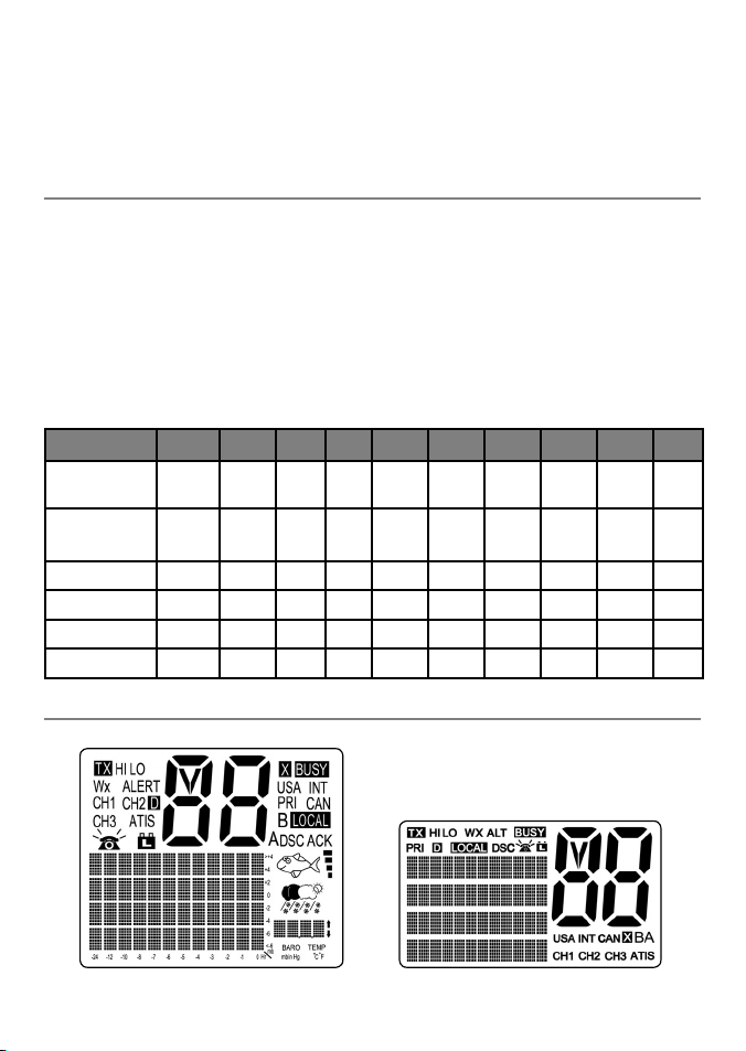
1-5 LCD Symbols an d Meanings
The simulation shows the locations of all the following information symbols on the LCD displays.
Optional handset displayBase unit display
7Northstar Explorer VHF Series: 721US, 721EU Operation and Installation Manual
Page 8
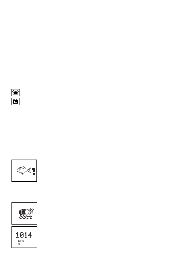
These symbols may not appear at all or may be shown in a different location on the optional handset.
Symbol Meaning
TX Transmitting.
HI LO Transmission power. High (HI) 25 W or Low (LO) 1 W.
WX Weather channel.
WX ALT Weather Alert. Alarm beeps will sound. 721US only.
BUSY Receiver busy with an incoming signal.
PRI Priority channel is selected.
D Duplex operation. Otherwise, blank for Simplex operation.
LOCAL Local calling is selected. Otherwise, blank for distance calling.
DSC DSC capability is available.
Indicates an incoming DSC call, or blinks to notify you of any unread Call Log
messages
Low Battery warning (activates at 10.5 V)
88 Channel selected.
USA INT CAN Selected channel bank for VHF radio operations and regulations.
X Channel is temporarily deleted from the ALL SCAN operation.
B A Channel suffi x, if applicable.
CH1 CH2 CH3 Shows which of the 3 favorite channels, if any, are selected.
Otherwise blank.
ATIS Enabled for use in European inland waterways. Otherwise blank. 721EU only.
DSC DSC capability is available.
ACK A message acknowledging your DSC call is being displayed.
Happy Fish symbol with one to four indicator bars to show the probability of good
fi shing at your current location, based upon barometric pressure and air temperature. Four bars show that good fi shing is likely. High pressure trends are associated
with stable conditions and calm seas. Research indicates that best fi shing occurs
when barometric pressure is rising and between 1010 and 1022 mb. During these
opportune conditions, most fi sh are thought to feed anywhere within the water
column. However, low pressure trends bring stormy seas and aff ect air bladders,
and these conditions make fi sh move to deeper levels and become less active.
Local weather forecast based on the local temperature and stored barometric pres-
sure data. The icons are indicative only and are more accurate close to land rather
than in open sea.
Digital Readout of the current barometric pressure (in mb or in/Hg) or the current
temperature (in ºC or ºF), depending upon your selection.
8 Northstar Explorer VHF Series: 721US, 721EU Operation and Installation Manual
Page 9
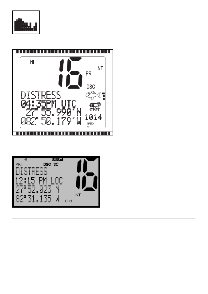
Baro Graph. A histogram of barometric pressure readings over the past 24 hours.
A typical operational display on base unit LCD:
A typical operational display on Optional Handset LCD:
The high-resolution histogram centers automatically if the range goes off scale.
Readouts are taken even when the engine and radio have been powered down
(with typically less than 3mA of current drain).
A transmission on Channel 16 is being
made at high power using the International
channel bank .
Channel 16 is set as the Priority channel.
There is an incoming DSC DISTRESS call so
the receiver is busy.
The latitude and longitude of the vessel
and UTC time are shown.
3 bars by the Happy Fish indicates rising
barometic trends and reasonable fishing
conditions.
The weather indicates shower y conditions.
1-6 How the Micropho ne and Optional Handse t Work Together
If you have the optional handset installed, as well as the microphone:
• neither item works when both are ON hook, but you can hear the audio from the handset
speaker and adjust the handset volume.
• to use one item when it’s OFF hook, the other item must be ON hook.
• if both items are OFF hook, only the microphone works.
• in Intercom mode ONLY, both items work OFF hook.
9Northstar Explorer VHF Series: 721US, 721EU Operation and Installation Manual
Page 10
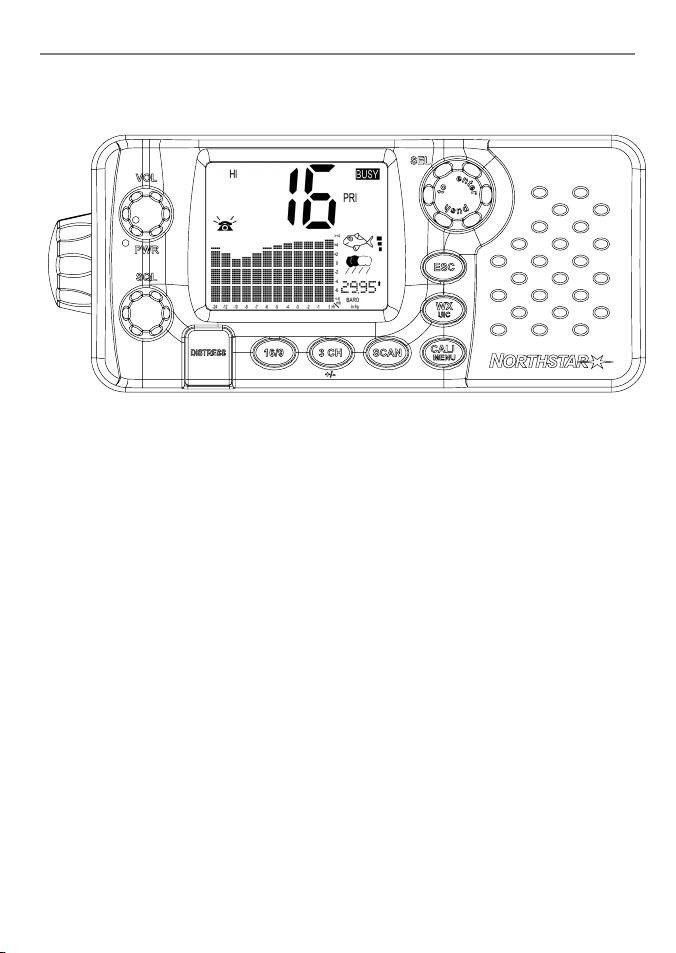
1-7 Basic Operation and Key Func tions
Explorer 721
All possible keys on the base unit, the microphone, and the optional handset are listed and their functions
are explained.
NOTE: Some keys or functions may not be available on your particular model of base unit, microphone, or optional
handset. This example shows the 721US base unit.
Key Function
VOL PWR Volume and Power. Turn clockwise to power on. Continue to turn until a comfortable
SQL Squelch or Threshold Level. Sets the threshold level for the minimum receiver
In areas of high noise (eg close to large cities) reception may improve if sensitivity
DISTRESS Send DSC Distress Call. See Section 6.
16/9 Priority Channel. 721US only. Press to cancel all other modes and to tune into the
The default is Channel 16. To make Channel 09 the priority channel, hold down 16/9
16 Priority Channel. 721EU only. Press to cancel all other modes and to tune into the
3 CH Three Favorite Channels. Press to toggle between your favorite channels. The
To scan only one of your favorite channels, press 3CH then immediately press and
volume is reached. VOL/PWR will also adjust the settings of an external speaker, if
connected.
signal. Turn fully counterclockwise until random noise is heard, then turn slowly
clockwise until the random noise disappears. Make another 1/4 turn clockwise for
best reception in open sea conditions.
is reduced. Either turn SQL slowly clockwise or use the LOCAL setting. See section
2.4.
priority channel. Press again to return to your original channel.
until a beep sounds and 09 is displayed.
priority channel, Channel 16, on high power. Press again to return to your original
channel.
CH1, CH2, or CH3 symbol appears on the LCD to show which favorite channel is
selected.
release SCAN. If you want to scan all three favorite channels, press 3CH then immediately press and hold SCAN.
10 Northstar Explorer VHF Series: 721US, 721EU Operation and Installation Manual
Page 11

To add a favorite channel for the fi rst time, select that channel then hold 3CH to store
it in the CH1 location. Repeat the procedure to store two more favorite channels in
the CH2 and CH3 locations respectively.
If you try and add another favorite channel it will overwrite the existing CH3. CH1
and CH2 remain unless you delete them.
To delete a favorite channel, select that channel then hold down 3CH until the CH1,
CH2 or CH3 symbol disappears off the LCD.
SCAN Scan. Scanning is not allowed in some European countries. Otherwise, press to
scan between your current channel and the priority channel in DUAL or TRI WATCH
mode. The weather channel is also scanned if the USA channel bank is selected and
the weather alert mode is ON.
Hold down SCAN to enter ALL SCAN mode where the priority channel is checked
every 1.5 seconds.
When a signal is received, scanning stops at that channel and BUSY appears on the
LCD. If the signal stops for more than 5 seconds, the scan restarts.
Press ENT or push the rotary knob to temporarily skip over (lock out) an “always busy”
channel when in ALL SCAN mode and resume the scan. An X is shown on the LCD
to designate a skipped channel. It’s not possible to skip over the priority channel.
Press SCAN to stop at the curr.ent channel.
CALL/MENU Radio Menu, DSC Set up Menu, Radio Set up Menu and DSC CALL Menu.
Hold down to show the radio menu (see Section 2) and to access the radio set up
menu (see Section 3) and the DSC set up menu (see Section 4).
Press to enter the DSC call menu and to make DSC calls (see Section 5).
WX Weather Channel. 721US only. In USA and Canadian waters, press to hear the most
recently selected weather station. The WX symbol is displayed on the LCD.
Press CH + or CH - to change to a diff erent weather channel. Press WX again to
return to the most recent channel.
If the weather alert mode is ON and an alert tone of 1050 Hz is broadcast from the
weather station, it’s picked up automatically and the alarm sounds. Press any key
to hear the weather alert voice message.
IC or H/L IC Intercom. Optional 701US or 701EU handset required. Hold down to enter Intercom mode
on USA models. EU models need just a single press and release.. This disables the radio
receiver except for incoming DSC calls and the intercom calls the other unit.
Press PTT when invited. When you’re fi nished, press ESC to exit Intercom mode or
put the handset back on hook.
ESC Escape. Use ESC when navigating menus, to clear incorrect entries, to exit from a
menu without saving changes, and to back up to the previous screen.
Rotary knob Channel Select. Turn to select a channel. The current channel is shown on the LCD
in BIG digits with an A or B designator suffi x (if applicable) in small letters below the
channel number. (See Appendix C for a listing of channel frequencies.)
Push to activate the ENTER function.
You can also use the rotary knob for alphanumeric entry if you don’t have an alpha-
numeric micrphone. Turn to step through alphanumeric characters one at a time
then push to confi rm each selection. If you make an error, select the < character
then push to backup.
11Northstar Explorer VHF Series: 721US, 721EU Operation and Installation Manual
Page 12

info Information. Press on the base MIKE to toggle through the INFO display to show
the barometric historgram, the barometric readout and temperature, or the Signalto-Noise Ratio (SNR).
H/L Transmission Power. High (HI) 25 W or Low (LO) 1 W. Press to toggle between high
or low transmission power for the entire channel bank. The HI or LO selection is
shown on the LCD.
Some channels allow only low power transmissions. Error beeps will sound if the
power transmission setting is incorrect.
Some channels allow only low power transmissions initially, but can be changed
to high power by holding down H/L and PTT at the same time. See Appendix C for
a complete listing of channel charts.
+ CH - Channel Select. Press CH + or CH - to step through the available channels one at a
time, or hold down to scroll rapidly through all the available channels. The current
channel is shown on the LCD in BIG digits with an A or B designator suffi x (if applicable) in small letters below the channel number. (See Appendix C for a listing
of channel frequencies.)
Press CH + or CH - to scroll the cursor up and down menu options on the LCD when
navigating menus.
When editing an item containing only numbers, press CH - to step through the
numbers or hold down to scroll rapidly.
To enter a character, press Ch = to step through the alphabet or hold down to scroll
rapidly.
ENT Enter. Press ENT when navigating menus, to confi rm entries and edits.
PTT Press To Talk. Press PTT to transmit at any time on an allowable channel. This auto-
matically exits you from menu mode and stops scanning.
You must release PTT to receive a signal.
If PT T sticks, a built-in timer will automatically shut down a transmission after fi ve
minutes and sound the error beeps. This timer is required by FCC regulations.
12 Northstar Explorer VHF Series: 721US, 721EU Operation and Installation Manual
Page 13
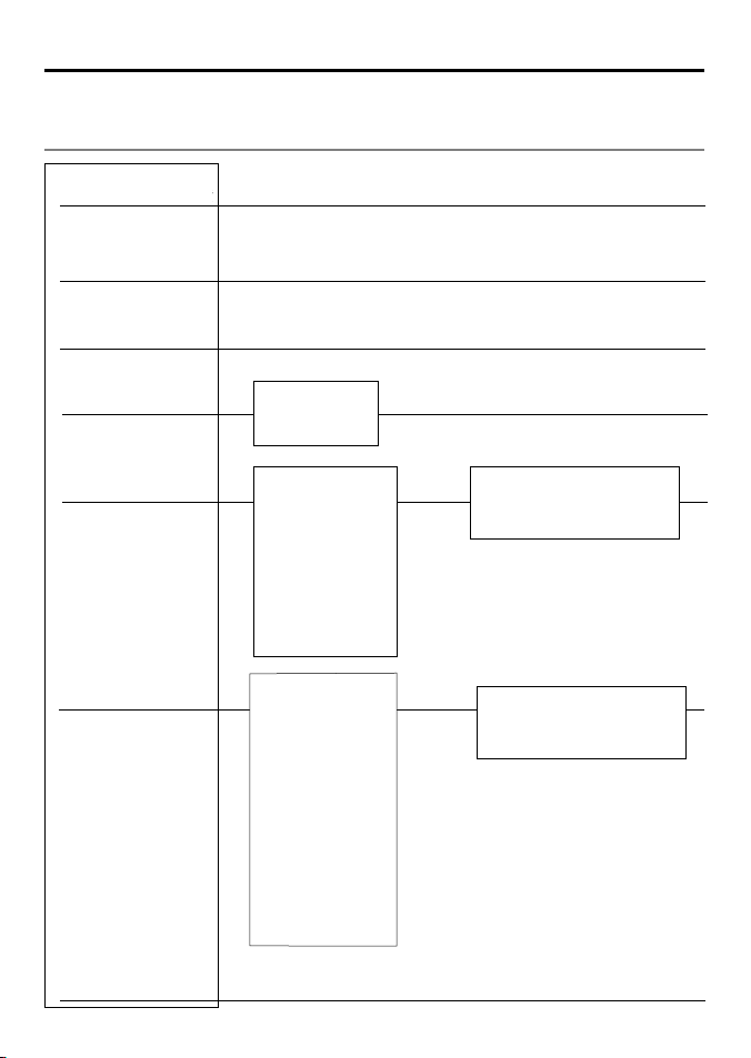
Section 2 - The Radio Menu (MENU)
I
(
Handset only
)
LO
O
/
A
DSC SETUP
UP
S
ly)
Hold down CALL/MENU to show the radio menu options.
Sections 1-3 and 1-4 explain how to navigate around the menu and enter, save and change data.
2-1 The Radio Menu Options (MENU )
Show weather, SNR or Happy Fish information on the handset.
NFO DATA
See Section 2-2.
BUDDY LIST
CAL/DIST
BACKLIGHT
C
NTRAST
GPS
DAT
RADIO SET
GPS SIM
RE
ET (Base unit on
Maintain your buddy list.
See Section 2-3.
Set backlight level.
See Section 2-5.
MANUAL
SETTING
USER MMSID
GROUP SETUP
INDIV REPLY
DSC FUNC
ATIS MMSID
ATIS FUNC
LL REPLY
UIC
CH NAME
RING VOLUME
KEY BEEP
INT SPEAKER
WATCH MODE
WX ALERT
COM PORT
BARO SENSOR
TEMPERATURE
HAPPY FISH
Turn the GPS Simulator on/off .
See Section 2.7.
(EU only)
(721US only)
(721US only)
Set radio sensitivity.
See Section 2-4.
Set contrast level.
See Section 2-5.
Set position & UTC manually.
See Section 2-6.
Set local time and time format.
See Section 2-6.
DSC SETUP Menu.
See Section 4.
RADIO SETUP Menu.
See Section 3.
Reset factory settings.
See Section 2.8.
13Northstar Explorer VHF Series: 721US, 721EU Operation and Installation Manual
Page 14

2-2 Show Weather, SNR or Happy Fish on Handset (INFO DATA)
If you have the optional handset installed, you can use INFO DATA to show the local weather forecast
(e.g. SUNNY) and a digital readout of the current barometric pressure (mb or in-Hg) and the channel
name on the handset LCD.
MENU SELECT
>INFO DATA
BUDDY LIST
LOCAL/DIST
INFO DATA
>ON
OFF
After INFO DATA is selected ON, the following screen appears on the handset with Line #3 able to display 3
items of interest - temperature, Signal To Noise ratio (SNR) or HAPPY FISH quality.
• a digital readout of the current air temperature (°F or °C)
• the current Signal-to- Noise Ratio (SNR)
• the Happy Fish symbol with indicator bars.
1. Hold down CALL/MENU to display the radio menu.
2. The cursor is at INFO DATA. Press ENT then select INFO ON to display the information on the handset
LCD, instead of the time and GPS position.
3. 78.4°F is replaced by SNR bars if handset is OFF HOOK.
4. Happy Fish symbol replaces TEMP/SNR if triggered after which it times out.
DISTRESS
A BIT CLOUDY
78.4
°F
29.99in-Hg
14 Northstar Explorer VHF Series: 721US, 721EU Operation and Installation Manual
Page 15
2-3 Maintain Your Buddy Li st (BUDDY LIST)
Use the Buddy List to store the names and associated MMSIDs of 20 favorite people.
MENU SELECT
>BUDDY LIST
The following sections show to use BUDDY LIST to add, edit, and delete entries in
LOCAL/DIST
BACKLIGHT
Section 3 explains how to call a buddy.
Names are stored in the order of entry, with the most recent entry shown fi rst.
your buddy list.
2-3-1 Add an Entry
BUDDY LIST
> MANUAL NEW
ALEX
TOM
1. Select BUDDY LIST. The cursor is at MANUAL NEW. Press ENT.
2. Enter the buddy name, one character at a time (this may be alphanumeric) then press ENT or push
the rotary k nob repeatedly until the cursor moves to the MMSID entry line.
3. Enter the MMSID (this must be numeric) associated with that buddy name then press ENT.
4. The new buddy name and MMSID are displayed. Press ENT or push the rotary knob to store the new
entry, which is displayed at the top of your buddy list.
NOTE: When the BUDDY LIST is full (20 entries), you can’t make a n ew entry until you have deleted an existi ng
entry
.
ENTER NAME
––––––––––––
ENTER MMSID
–––––––––
ENTER NAME
BOB
ENTER MMSID
123456789
BOB
123456789
> STORE
CANCEL
2-3-2 Edit an Entry
BUDDY LIST
> MANUAL NEW
ALEX
TOM
ALEX
> EDIT
DELETE
EDIT NAME
ALEX
EDIT MMSID
112233445
1. Select BUDDY LIST. Press ENT or push the rotary knob to display the list of entries.
2. Scroll down (if required) to the incorrect entry and press ENT.
3. Select EDIT. The cursor is at the first character of the name.
4. Edit the buddy name or, to edit only the MMSID, press ENT or push the rotary knob repeatedly until
the cursor moves to the MMSID line.
5. When you are finished, press ENT or push the rotary knob (repeatedly if necessary) to display the
next screen.
6. Press ENT or push the rotary knob to store the changes. The buddy list is displayed again. If more
changes are required, repeat Steps 2 thru 6. Otherwise, press ESC to exit.
ALEX
111223344
> STORE
CANCEL
15Northstar Explorer VHF Series: 721US, 721EU Operation and Installation Manual
Page 16
2-3-3 Delete an En try
BUDDY LIST
> MANUAL NEW
ALEX
TOM
BUDDY LIST
> MANUAL NEW
ALEX
TOM
TOM
> EDIT
DELETE
DELETE BUDDY
TOM
> YES
NO
1. Select BUDDY LIST. Press ENT or push the rotary knob to display the list of entries.
2. Scroll down (if required) to the entry you want to delete and press ENT.
3. Select DELETE then select YES.
4. The entry is deleted immediately and the buddy list is displayed again.
2-4 Local or Distan ce Sensitivity (LOCAL/D IST)
Use LOCAL/DIST to improve the sensitivity of the receiver either locally (LOCAL) or
MENU SELECT
INFO DATA
LOCAL is NOT recommended for use in open sea conditions. It’s designed for use
BUDDY LIST
> LOCAL/DIST
See also SQL (Squelch Control) in Section 1.6.
over distances (DIST).
in areas of high radio noise; e.g. when you’re close to a city.
2-4-1 Set Distance Sensitivi ty
SENSITIVITY
> DISTANT
LOCAL
1. Select LOCAL/DIST then select DIST.
2. Press ENT or push the rotary knob to activate the DIST setting. This disables
local sensitivity and the menu is displayed again.
2-4-2 Set Local Sensitivit y
SENSITIVITY
DISTANT
> LOCAL
LOCAL is displayed on the LCD in reverse video, as a reminder that local sensitivity is selected.
1. Select LOCAL/DIST then scroll to LOCAL.
2. Press ENT or push the rotary knob to activate the LOCAL setting. This disables
distance sensitivity and the menu is displayed again.
2-5 Backlighting (BACKLIGHT ) and Contrast (CONTRAST)
MENU SELECT
LOCAL/DIST
> BACKLIGHT
CONTRAST
16 Northstar Explorer VHF Series: 721US, 721EU Operation and Installation Manual
Use BACKLIGHT to set the backlight levels for the LCD at a comfortable level.
The microphone keypad backlighting is either ON or OFF.
The DISTRESS key backlighting can’t be switched off .
Use CONTRAST to set the contrast level for the LCD.
Page 17
2-5-1 Set the Backlig hting Level
BACKLIGHT
LO HI
PRESS ENT
1. Select BACKLIGHT.
2. Use CH + or CH - to select a comfortable backlight level.
3. Press ENT or push the rotary knob to confi rm the new level and return to the
menu.
2-5-2 Set the Contrast Le vel
1. Select CONTRAST.
CONTRAST
LO HI
PRESS ENT
2. Use CH + or CH - to select a comfortable contrast level.
3. Press ENT or push the rotary knob to confi rm the new level and return to the
menu.
2-6 GPS Data and Time (GPS/DATA)
MENU SELECT
BACKLIGHT
CONTRAST
> GPS/DATA
This information is important because it will be used if you transmit a DSC distress call.
If your vessel has an operational GPS navigation receiver, the radio automatically
detects and updates the vessel position and the local time.
However, if the GPS navigation receiver is disconnected or absent, you can specify
the vessel position and the local time manually, using the GPS/DATA option.
2-6-1 Manually Ente r Position a nd UTC Time (MANUAL)
NOTE: This function is available only when an operational GPS receiver is NOT connected.
GPS/DATA
> MANUAL
SETTING
1. Select GPS/DATA, then MANUAL.
2. Enter the latitude, then the longitude, then the UTC.
3. Press ENT or push the rotary knob when all the information is correct.
The vessel’s latitude and longitude are shown on the screen, with the UTC time. After entering your
manual LL position, the prefi x “M” in the normal GPS screen indicates a manual entr y. The manual entries
are cancelled if a real GPS position is received.
MANUAL LL
––’ ––’ ––––N
––’ ––’ ––––W
MAN ––:––UTC
17Northstar Explorer VHF Series: 721US, 721EU Operation and Installation Manual
Page 18
2-6-2 Local Time (TIME OFFSET)
The local time can be set by entering the time off set between UTC and local time as follows.
GPS/DATA
MANUAL
>SETTING
GPS/DATA
> TIME OFFSET
TIME FORMAT
TIME DISPLY
TIME OFFSET
>+01:30
02:30PM LOC
1. Select GPS/DATA, then SETTING.
2. Select TIME OFFSET to enter the diff erence between UTC and local time. Half hour increments can be
used with a maximum off set of ±13 hours.
In this example, a diff erence of +1.5 hours has been entered and the local time is displayed with the
suffi x LOC.
L
L
W
M
Y
X
V
M
V
International Date Line
X
W
M
†
M
M*
*
V
X
W
M
W
*
M
W
M
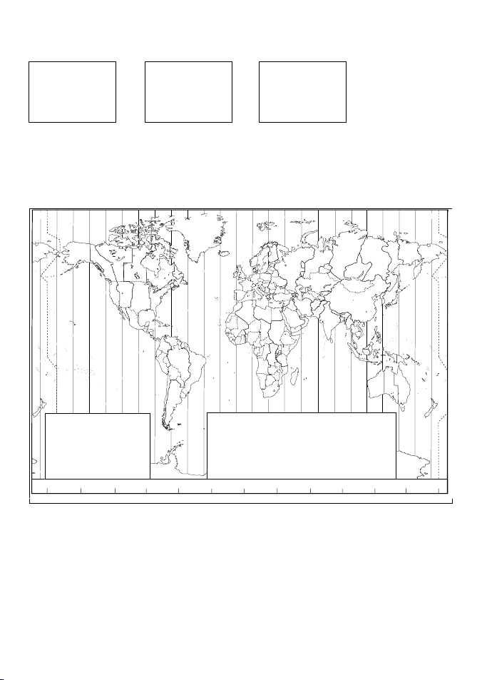
STANDARD TIME ZONES
Daylight Saving Time (Summer Time),
usually one hour in advance of Standard
Map outline © Mountain High Maps
Compiled by HM Nautical Almanac Office
180°
U
Corrected to January 2005
Zone boundaries are approximate
Time, is kept in some places
150°W
U
U
120°W
Q
S
T
R
S
R
T
S
T
R
S
R
R
S
R
S
S
Q
P
90°W
Z
Q
Q
P
60°W
O
P
‡
P
Z
N
Z
N
Z
Z
P*
Q
P
P
Q
O
N
30°W
A
Z
Z
N
P
A
O
Z
O
Z
m
Z
0
A
+1
B
+2
C
+3
C*
+330
D
+4
D*
+430
E
+5
0°
C D F
A
B
A
B
A
B
B
B
A
C
Z
B
A
E
G
D
E
H
F
C
D
D
F
E
D
*
C
C
C
C
D
C
C
D
H
*
D
E
*
D
F
*
E
F
G
*
E
*
E
E
F
G
F
*
F
B
Standard Time = Universal Time + value from table
h
E*
+530
F
+6
F*
+630
G
+7
H
+8
I
+9
I*
+930
‡
30°E
m
h
m
K
+10
K*
+10 30
L
+11
L*
+11 30
M
+12
M*
+13
M†
+14
No Standard Time legallyadopted
60°E
m
h
N
-1
O
-2
P
-3
P*
-330
Q
-4
R
-5
S
-6
90°E
G
H
K
I
L
M Y
K
L
I
H
I
H
H
H
I
G
H
H
hh
T
-7
U
-8
U*
-830
V
-9
V*
-930
W
-10
X
-11
Y
-12
120°E
M
K
International Date Line
L
I
I
I
I*
m
K
I
K
K
K
150°E
X
M
M
K
L
L
M
L
M
*
L
*
K
M
M
‡
180°
*
18 Northstar Explorer VHF Series: 721US, 721EU Operation and Installation Manual
Page 19

2-6-3 Time Format Option s (TIME FORMAT)
Time can be shown in 12 or 24 hour format.
GPS/DATA
MANUAL
> SETTING
SETTING
TIME OFFSET
> TIME FORMAT
TIME DISPLAY
TIME FORMAT
> 12 Hr
24 Hr
07:15AM LOC
1. Selec t GPS/DATA, then SETTING.
2. Select TIME FORMAT.
3. Select 12 Hr or 24 Hr as desired. In this example, 12 hour format has been selected so the LCD shows
the AM or PM suffix.
2-6-4 Time Di splay Options (TIME DISPLAY)
If you’ve entered the time manually as described in the previous sections, the time is shown ALWAYS with
the prefi x M.
However, if the vessel’s position is being updated through a GPS navigation receiver, you can switch the time
display ON or OFF as follows:
GPS/DATA
TIME OFFSET
TIME FORMAT
> TIME DISPLY
TIME DISPLY
ON
> OFF
1. Select GPS/DATA, then SETTING.
2. Select TIME DISPLY.
3. Select ON or OFF as desired. In this example,
OFF has been selected and so the LCD no
longer shows the time.
If the time display is set ON, course and speed data are NOT displayed on the LCD (see
section 2-5-6).
2-6-5 Position Dis play Options (LL displa y)
If you’ve entered the vessel position manually as described in the previous section, the vessel position is
shown ALWAYS with the suffi x M.
However, if the time is being updated through a GPS navigation receiver, you can switch the vessel position
display ON or OFF as follows:
GPS/DATA
TIME FORMAT
TIME DISPLY
> LL DISPLAY
LL DISPLAY
ON
> OFF
1. Select GPS/DATA, then SETTING.
2. Select LL DISPLAY.
3. Select ON or OFF as desired. In this example,
OFF has been selected and the screen no
longer shows the vessel position.
2-6-6 Course & Spe ed Display Options (COG/SOG )
Use this option to display course over ground (COG) and speed over ground (SOG) data on the screen.
GPS/DATA
TIME DISPLY
LL DISPLY
> COG/SOG
COG/SOG
> ON
OFF
If COG/SOG is set ON, the time is NOT displayed on the screen (see section 2-5-4).
1. Select GPS/DATA, then SETTING.
2. Select COG/SOG.
3. Select ON or OFF as desired. In this example,
ON has been selected, so the screen shows the
bearing and speed.
19Northstar Explorer VHF Series: 721US, 721EU Operation and Installation Manual
Page 20
2-6-7 GPS Alert Opt ions (ALERT)
The GPS alert is usually set to ON so that if the GPS navigation receiver is disconnected, the alarm sounds.
GPS/DATA
LL DISPLY
COG/SOG
> GPS ALERT
GPS ALERT
> ON
OFF
1. Select GPS/DATA, then SETTING.
2. Select GPS ALERT.
3. Select ON or OFF as desired.
2-7 GPS Simulator (GPS SIM)
The GPS Simulator is set to OFF whenever the radio is turned ON or whenever real GPS data is available through
the COM port. However, if you want to test the GPS Simulator, turn it ON as follows:
MENU SELECT
DSC SETUP
RADIO SETUP
> GPS SIM
1. Select GPS SIM, then select ON or OFF as desired.
Whenever the GPS Simulator is turned ON, simulated Speed Over Ground
(SOG), Course Over Ground (COG), and LL position appear on the screen. This
data is updated automatically during the simulation.
IMPORTANT: It’s not possible to send a DSC transmission when you’re in GPS Simulator mode.
2-8 Reset to Factor y Defaults (RESET)
Use RESET to return every setting to the factory defaults EXCEPT all MMSID settings and the entries in your
buddy list.
MENU SELECT
RADIO SETUP
GPS SIM
> RESET
1. Selec t RESET. The radio asks for confirmation.
2. Select YES to reset the radio and return to the menu.
RESET RADIO
ARE YOU SURE
> YES
NO
20 Northstar Explorer VHF Series: 721US, 721EU Operation and Installation Manual
Page 21
Section 3 - Radio Setup Menu (RADIO SETUP)
Hold down CALL/MENU then scroll down and select RADIO SETUP. Press ENT or push the rotary knob to show
the RADIO SETUP menu options.
Sections 1-3 and 1-4 explain how to navigate around the menu and enter, save and change data.
3-1 The Radio Setup Menu Optio ns (RADIO SETUP)
UIC (721US only)
CH NAME
RING VOLUME
KEY BEEP
INT SPEAKER
WATCH MODE
WX ALERT (721US only)
COM PORT
BARO SENSOR
TEMPERATURE
HAPPY FISH
Select the channel bank (721US only)
See Section 3-2.
Edit or delete channel names.
See Section 3-3.
Set the volume level of the incoming call notifi cation beeps.
See Section 3-4.
Set the volume level of the beeps.
See Section 3-4.
Turn the radio’s internal speakers ON or OFF.
See Section 3-5.
Select Dual or Tri watch scanning.
See Section 3-6.
Turn the WX Alert scanning mode ON or OFF. (721US only)
See Section 3-7.
Select NMEA or NAVBUS protocol for communications between the radio and any
other instruments.
See Section 3-8.
Select the barometric units, calibrate the sensor, turn the display ON or OFF.
See Section 3-9.
Select the temperature units, calibrate the sensor.
See Section 3-10.
Select the HAPPY FISH alarm to be ON or OFF.
See Section 3-11.
3-2 Select the Channe l Bank (UIC)
721US only.
There is a choice of three channel banks; USA, International, or Canadian (see Appendix C for details).
1. Select RADIO SETUP.
RADIO SETUP
> UIC
CH NAME
RING VOLUME
UIC
> USA
INT’L
CANADA
2. The cursor is at UIC. Press ENT or push the rotary
knob to display the list of channel banks.
3. Select the channel bank to use then press ENT
or push the rotary knob to confi rm the setting
and return to the menu.
21Northstar Explorer VHF Series: 721US, 721EU Operation and Installation Manual
Page 22
3-3 Change Channel Na mes (CH NAME)
The channel charts are listed in Appendix C with their default name tags. CH NAME gives you the option
to edit or delete the channel name tags displayed on the screen.
RADIO SETUP
> CH NAME
RING VOLUME
KEY BEEP
EDIT CH NAME
TELEPHONE
CH NAME 01
TELEPHONE
SAVE CH NAME
PHONE1
> YES
NO
TELEPHONE
> EDIT
DELETE
1. Select RADIO SETUP, then CH NAME.
2. Use CH + or CH - to step through the channels with their names until you see the channel name you
want to change, then press ENT or push the rotary knob. In this example, the channel name TELEPHONE
associated with channel 01 is being changed to PHONE1.
3. Select EDIT and press ENT or push the rotary knob to edit the existing name tag. Enter the new name
over the existing name. It can be a maximum of 12 characters.
To delete the channel name, just select DELETE then press ENT or push the rotary knob.
4. Press ENT or push the rotary knob (repeatedly if necessary) to display the YES/NO confi rmation.
5. Press ENT or push the rotary knob to confi rm the new channel name tag or the deletion, then press
ESC to return to the menu.
3-4 Ring and Bee p Volume (RING VOLUME) and (KEY BEEP)
Set the volume level of the incoming signal beeps (RING VOLUME) and/or the error and warning beeps (KEY
BEEP) as follows:
RADIO SETUP
> CH NAME
RING VOLUME
KEY BEEP
RING VOLUME
> HIGH
LOW
KEY BEEP
> HIGH
LOW
OFF
1. Select RADIO SETUP, then RING VOLUME or KEY BEEP as appropriate.
2. Select a HIGH or LOW volume. (You can turn the beeps off completely by selecting KEY BEEP then
OFF.)
3. Press ENT or push the rotary knob to confi rm the new volume setting and return to the menu.
3-5 Internal Speake r Connections (INT SPEAKER)
Switch the radio’s internal speaker ON or OFF. (The external speaker is always ON if a speaker is plugged into
the external speaker jack.)
RADIO SETUP
RING VOLUME
KEY BEEP
> INT SPEAKER
INT SPEAKER
> ON
OFF
1. Select RADIO SETUP, then INT SPEAKER.
2. Select ON or OFF then press ENT or push the
rotary knob to confi rm the setting and return
to the menu.
22 Northstar Explorer VHF Series: 721US, 721EU Operation and Installation Manual
Page 23
3-6 Set the Priorit y Channel (WATCH MODE)
If you have the 721EU, watch mode is similar to a dual watch, scanning between the priority channel and the
working channel. CH16 is the priority channel.
If you have the 721US and are operating on USA or Canadian channel banks, you can set the priority channel
to cover both CH16 and CH09 as well as the working channel, as follows:
RADIO SETUP
KEY BEEP
INT SPEAKER
> WATCH MODE
WATCH MODE
> ONLY 16CH
16CH+9CH
1. Select RADIO SETUP, then WATCH MODE.
2. Select ONLY 16CH for dual watch mode, or
16CH+9CH for tri watch mode.
3-7 Weather Aler t (WX ALERT)
721US only.
The NOAA provides several weather forecast channels on USA and Canadian channel banks. If severe weather
such as storms or hurricanes are forecast, the NOAA broadcasts a weather alert on 1050 Hz. You can set up
the radio to pick up weather alerts, as follows:
1. Select RADIO SETUP, then WX ALERT.
2. Select ON then press ENT or push the rotary
RADIO SETUP
INT SPEAKER
WATCH MODE
> WX ALERT
WX ALERT
ON
> OFF
knob to confi rm the setting and return to the
menu. (If you select OFF, the alarm won’t sound
when there’s a weather alert.)
3. When a weather alert is broadcast, the alarm
will sound. Press any key to hear the weather
alert voice message.
3-8 NMEA or NAVBUS protocol (COM PORT )
You can add the radio to a group of instruments using NMEA or NAVBUS protocol.
NAVBUS is automatically activated when present, so that data such as barometric pressure and history,
temperature, DSC polling positions and distress data are available to any other Northstar instruments using
NAVBUS. However, the barometric and temperature readings from the radio can be turned OFF if you prefer
to use the readings from a diff erent instrument.
Select your GPS data source to come from either NMEA or NAVBUS as follows:
3-8-1 NMEA GPS data source (GPS SOURCE)
RADIO SETUP
WATCH MODE
WX ALERT
> COM PORT
COM PORT
NMEA
> GPS SOURCE
BARO & TEMP
GPS SOURCE
> NMEA
NAVBUS
GPS SOURCE
NMEA
> ON
OFF
1. Select RADIO SETUP, then COM PORT.
NMEA
CHECKSUM
> ON
OFF
2. Select GPS source, then select NMEA.
3. The cursor is at ON. Press ENT or push the
rotary knob to confi rm the setting and show
the CHECKSUM option.
4. CHECKSUM ON is the usual setting. The cursor is at ON. Press ENT or push the rotary knob to confi rm
the setting and return to the menu.
23Northstar Explorer VHF Series: 721US, 721EU Operation and Installation Manual
Page 24
3-8-2 NAVMAN GPS data source (GPS SOURCE)
RADIO SETUP
WATCH MODE
WX ALERT
> COM PORT
COM PORT
NMEA
> GPS SOURCE
BARO & TEMP
GPS SOURCE
NMEA
> NAVBUS
1. Select RADIO SETUP, then COM PORT.
2. Select GPS source, then select NAVBUS.
3. The cursor is at ON. Press ENT or push the rotary knob to confi rm the setting and return to the menu.
GPS SOURCE
NAVBUS
> ON
OFF
3-8-3 Use the 721 as barometric pressu re and temperature da ta source (BARO & TEMP)
RADIO SETUP
WATCH MODE
WX ALERT
> COM PORT
COM PORT
NMEA
GPS SOURCE
> BARO & TEMP
BARO & TEMP
> ON
OFF
1. Select RADIO SETUP, then COM PORT.
2. Select BARO & TEMP.
3. The cursor is at ON. Select ON to have the radio provide the barometric and temperature data to other
instruments connected. Select OFF to have another instrument to act as the source of this data.
3-9 Barometric Displ ays (BARO SENSOR)
A barometric sensor in the microphone measures air pressure changes, enabling the radio to provide
three useful aids towards weather prediction and fishing conditions, particularly when you’re close to
large land masses. (See the information on the Happy Fish icon in Sec tion 1.5.) The radio can show:
• a weather icon to indicate five different conditions (SUNNY, PARTLY CLOUDY, CLOUDY, RAINY,
SNOW). The local air pressure trends combined with the local temperature determines which
weather icon is displayed. (NOTE: In open ocean conditions the weather icon can be less
accurate than when close to large land masses.)
• a digital readout of air pressure (in mb or in/Hg).
• a graphical display of barometric pressure changes over the past consecutive 24 hours.
Barometric data is maintained even if the radio is switched
off.
NOTE: If the vessel Batter y Master is turned OFF, the BARO history is erased.
3-9-1 Set the Barometric Unit s (BARO UNITS)
RADIO SETUP
WX ALERT
COM PORT
> BARO SENSOR
BARO SENSOR
> BARO UNITS
BARO DISPLY
BARO CAL.
1. Select RADIO SETUP, then BARO SENSOR.
2. The cursor is at BARO UNITS. Press ENT or press the rotary knob.
3. The cursor is at MILLIBARS. Press ENT or press the rotary knob to show barometric pressure in MILLIBARS
or select INCHES to show barometric pressure in inches of mercury.
BARO UNITS
> MILLIBARS
INCHES
24 Northstar Explorer VHF Series: 721US, 721EU Operation and Installation Manual
Page 25

3-9-2 Switch the Barometric Di splay ON or OFF (BARO DISPLY)
RADIO SETUP
WX ALERT
COM PORT
> BARO SENSOR
BARO SENSOR
BARO UNITS
> BARO DISPLY
BARO CAL.
1. Select RADIO SETUP, then BARO SENSOR.
2. Select BARO DISPLY.
3. The cursor is at LCD OFF. Press ENT or press the rotary knob to switch OFF the barometric display on the
base unit, or select LCD ON to show the barometric display on the base unit.
IMPORTANT: LCD OFF is the default. This minimises the current drain of the standby vessel battery to about
3mA average. If the barometric display is set to LCD ON the current drain is continuous at about 85mA.
BARO DISPLY
> LCD OFF
LCD ON
3-9-3 Calibrate the Barome tric Sensor (BARO CAL.)
The barometric functions and icons work best when calibrated to local conditions. The operating range
is from 960mb to 1060mb.
RADIO SETUP
WX ALERT
COM PORT
> BARO SENSOR
BARO SENSOR
BARO UNITS
BARO DISPLY
> CAL
CAL
MODIFY?
> ± 0.00 In-Hg
PRESS ENT
1. Select RADIO SETUP, then BARO SENSOR.
2. Select BARO CAL. then change the setting to match the reading on an accurate instrument nearby or
the reading given by a local weather station.
3-10 Temperature Di splay (TEMPERATURE)
A temperature sensor in the microphone measures air temperature changes.
3-10-1 Set the Temperature Un its (UNITS)
RADIO SETUP
COM PORT
BARO SENSOR
> TEMPERATURE
TEMPERATURE
> UNITS
CAL.
1. Select RADIO SETUP, then TEMPERATURE
2. The cursor is at UNITS. Press ENT or press the rotary knob.
3. The cursor is at ºC. Press ENT or press the rotary knob to display the temperature in ºC (Celsius) or select
ºF to show the temperature in Fahrenheit.
TEMP SENSOR
> ˚C
˚F
3-10-2 Calibrate the Tempe rature Reading (CAL .)
The temperature sensor works best when calibrated to local conditions.
RADIO SETUP
COM PORT
BARO SENSOR
> TEMPERATURE
TEMPERATURE
> UNITS
CAL.
1. Select RADIO SETUP, then TEMPERATURE.
2. Select CAL. then change the setting to match the reading on an accurate instrument nearby or the
reading given by a local weather station.
CAL
MODIFY?
> ± 0.00 In-Hg
PRESS ENT
25Northstar Explorer VHF Series: 721US, 721EU Operation and Installation Manual
Page 26

Section 4 - DSC SETUP Menu
A valid user MMSID must be entered to access the DSC functions. If you don’t have a user MMSID, see
Appendix D.
Hold down CALL/MENU then scroll down and select DSC SETUP. Press ENT or push the rotary knob
to show the following DSC SE TUP menu options.
Sections 1.3 and 1.4 explain how to navigate around the menu and enter, save and change data.
4-1 DSC SETUP Menu Options
USER MMSID
GROUP SETUP
INDIV REPLY
ATIS MMSID
ATIS FUNC
DSC FUNC
LL REPLY
Check your user MMSID. See section 4.2. To enter your user MMSID for the fi rst time,
see Section 7-9.
Enter or change the name and/or details of a group.
See section 4.3.
Choose an automatic or manual response to calls (721US only).
See section 4.4.
Enter or change your ATIS MMSID (721EU only).
See section 4.5.
Enable/disable the ATIS function (VHF 721EU).
See section 4.5.
Turn the DSC operation ON or OFF.
See section 4.6.
Select the type of response to an LL polling request.
See section 4.7.
4-2 Check Your User MMSID (USER MMSID)
You can display and read your user MMSID at any time.
1. Select DSC SETUP.
2. The cursor is at USER MMSID. Press ENT or push the rotary knob.
3. The LCD shows your user name and MMSID.
4-3 Maintain Your Gr oups (GROUP SETUP)
Use GROUP SETUP to create, edit, or delete 1, 2, or 3 groups of frequently called people stored in alphanumeric
order. A group MMSID always starts with 0.
4-3-1 Create a Group (GROUP SETUP)
1. Select DSC SETUP, then GROUP SETUP.
2. If this is the FIRST TIME that you’re entering a group name, a line of nine zeros appears. Otherwise, any
existing group names are displayed. Press ENT or push the rotary knob to display the input screen.
3. Enter the group name along the dashed line. The group name can be alphanumeric. Press ENT or push
the rotary knob to confi rm each correct entry and to move to the next digit. When you are fi nished,
press ENT or push the rotary knob repeatedly until the cursor moves to the MMSID line.
26 Northstar Explorer VHF Series: 721US, 721EU Operation and Installation Manual
Page 27
DSC SETUP
USER MMSID
> GROUP SETUP
INDIV REPLY
GROUP SETUP
> MANUAL NEW
000000000
GROUP NAME
––––––––––––
GROUP MMSID
0––––––––
FISHER1
012345678
> STORE
CANCEL
If you make an error, select < and press ENT to backup and correct the entry (721US) or CLR and ENT
(721EU).
4. Enter the group MMSID. The fi rst number is always 0. Press ENT or push the rotary knob to confi rm the
entry.
5. The group name and group MMSID are shown in a confi rmation screen. Press ENT or push the rotary
knob to store the details and return to the GROUP SETUP screen.
4-3-2 Edit Group Name or Grou p MMSID
GROUP SETUP
MANUAL NEW
> FISHER1
FRIENDS1
FISHER1
> EDIT
DELETE
EDIT NAME
> FISHER1
EDIT MMSID
012345678
FISHER2
012345678
> STORE
CANCEL
1. Select DSC SETUP, then GROUP SETUP. The existing group names are displayed. Select the group name
that you want to edit.
2. The cursor is at EDIT. Press ENT or push the rotary knob to show the group name details. The cursor is
at the fi rst character of the group name.
3. Edit the new name or, to edit only the MMSID, press ENT or push the rotary knob repeatedly until the
cursor moves to the MMSID line.
4. When you are fi nished, press ENT or push the rotary knob (repeatedly if necessary) to display the next
screen.
5. Press ENT or push the rotary knob to store the changes and return to the GROUP SETUP screen.
4-3-3 Delete a Group
GROUP SETUP
MANUAL NEW
> FISHER2
FRIENDS1
FISHER2
EDIT
> DELETE
1. Select DSC SETUP, then GROUP SETUP.
2. Select the group that you want to delete.
3. Select DELETE and press ENT or press the rotary knob. The radio asks for confi rmation.
4. Press ENT or push the rotary knob to delete the group and return to the GROUP SETUP screen.
DELETE GROUP
FISHER2
> YES
NO
4-4 Respo nse to Individual Calls (INDIV REPLY)
721US only.
You can respond to incoming individual calls with an automatic response or with a manual response.
An automatic response sends an acknowledgement then sets the request link channel, ready for a
27Northstar Explorer VHF Series: 721US, 721EU Operation and Installation Manual
Page 28

conversa
tion.
A manual response asks if you want to acknowledge the call, and then asks if you want to converse with
the caller.
DSC SETUP
USER MMSID
GROUP SE TUP
> INDIV REPLY
INDIV REPLY
> AUTO
MANUAL
1. Select DSC SETUP, then select INDIV REPLY.
2. The cursor is at AUTO. Press ENT or press the
rotary knob for an automatic response, or select
MANUAL for a manual response.
4-5 ATIS MMSID & ATIS Functionality
721EU only.
You MUST enter your ATIS MMSID to access ATIS functionality if you are navigating inland waterways within
Europe. ATIS sends a digital message anytime that you release the PTT key. Inland waterways rules require
1 W Tx power on Channels 06, 08, 10, 11, 12, 13, 14, 15, 17, 71, 72, 74, and 77.
4-5-1 Enter or Edit Your ATIS MMSID
DSC SETUP
GROUP SE TUP
INDIV REPLY
> ATIS MMSID
ATIS MMSID
923456789
> STORE
CANCEL
INPUT ATIS
MMSID
9––––––––
INPUT ATIS
MMSID
> STORE
CANCEL
INPUT AGAIN
ATIS MMSID
9––––––––
To enter or edit your ATIS MMSID:
1. Select DSC SETUP, then ATIS MMSID.
2. If this is the FIRST TIME that you are entering your ATIS MMSID, a dashed line appears. Enter your ATIS
MMSID along the dashed line. An ATIS MMSID always starts with the number 9. Press ENT or push the
rotary knob to confi rm each correct entry and to move to the next digit.
If you make an error, press CH - until < appears, then press ENT or push the rotary knob to backup and
correct the entry.
If you’re editing an existing ATIS MMSID, this will be displayed. Make the required changes.
3. Press ENT or push the rotary knob to store your ATIS MMSID.
4. Enter your ATIS MMSID again as a password check, then press ENT or push the rotary knob to permanently
store the ATIS MMSID and return to the menu.
You can view your stored ATIS MMSID at anytime by selecting ATIS MMSID in the main menu.
4-5-2 Enable ATIS Functionali ty (ATIS FUNC)
721EU only.
ATIS functionality will operate only after the ATIS MMSID has been entered (see previous section).
1. Select DSC SETUP, then ATIS FUNC.
2. The cursor is at ON. Select ENT or push the rotary k nob to enable the ATIS functionality and automatically
disable DSC functionality. The ATIS annunciator appears on the screen.
28 Northstar Explorer VHF Series: 721US, 721EU Operation and Installation Manual
Page 29

DSC SETUP
INDIV REPLY
ATIS MMSID
> ATIS FUNC
ATIS FUNC
> ON
OFF
It’s not possible to have both ATIS ON and DSC ON simultaneously. When you enable one, the other will turn
OFF. If DSC and ATIS are both OFF, you must turn DSC ON for normal DSC operation.
The annunciator on the LCD shows you the current mode: if the DSC annunciator is shown, DSC is operational;
if the ATIS annunciator is shown, ATIS is operational.
4-6 DSC Funct ionality (DSC FUNC)
DSC functionality can be disabled but this is not recommended.
DSC SETUP
GROUP SE TUP
INDIV REPLY
> DSC FUNC
DSC FUNC
> ON
OFF
1. Select DSC SETUP, then DSC FUNC.
2. The cursor is at ON. Press ENT or push the rotary knob to enable the DSC functionality and automatically
disable ATIS functionality. The DSC annunciator appears on the screen.
It’s not possible to have both ATIS ON and DSC ON simultaneously. When you enable one, the other will turn
OFF. If DSC and ATIS are both OFF, you must turn DSC ON for normal DSC operation.
The annunciator on the LCD shows you the current mode: if the DSC annunciator is shown, DSC is operational;
if the ATIS annunciator is shown, ATIS is operational.
4-7 Response Type to LL Polling Ca lls (LL REPLY)
You can set up the radio to respond to an LL polling request in one of three ways:
AUTO automatically replies to an incoming LL polling request from any of your buddies.
MANUAL reply manually or ignore to each incoming LL polling request from your buddies.
OFF ignores all incoming LL polling requests. from your buddies.
DSC SETUP
INDIV REPLY
DSC FUNC
> LL REPLY
LL REPLY
> MANUAL
AUTO
OFF
1. Select DSC SETUP, then LL REPLY.
2. Select your mode of response and press ENT or
push the rotary knob to confi rm.
29Northstar Explorer VHF Series: 721US, 721EU Operation and Installation Manual
Page 30
Section 5 - Send and Receive DSC Calls
A valid user MMSID must have been entered to access the DSC functions. If you don’t have a user
MMSID, see Appendix D.
Press CALL/MENU to show the DSC CALL menu. This shows the different types of DSC call that you
make.
Sections 1.3 and 1.4 explain how to navigate around the menu and enter, save and change data.
5-1 What is DSC?
DSC (Digital Selective Calling) is a semi-automated method of establishing VHF, MF, and HF radio calls. It
has been designated as an international standard by the IMO (International Maritime Organization) and is
part of the GMDSS (Global Maritime Distress and Safety System).
Currently, you are required to monitor Distress Channel 16, but DSC will eventually replace listening watches
on distress frequencies and will be used to broadcast routine and urgent maritime safety information.
DSC enables you to send and receive calls from any vessel or coast station that is equipped with DSC
functionality, and within geographic range. Calls can be categorised as distress, urgency, safety, or routine,
and DSC selects a working channel automatically.
5-2 The DSC CALL Menu Optio ns
Make a routine, safety, urgency or distress call to a
INDIVIDUAL
LAST CALL
GROUP
ALL SHIPS
CALL LOG
DIST LOG
LL REQUEST
ROUTINE
SAFETY
URGENCY
DISTRESS
URGENCY
SAFETY
ROUTINE
DISTRESS
buddy or another individual.
See Section 5-3.
Show the details of the most recent incoming call.
See Section 5-4.
Make a call to one of your three groups.
See Section 5-5.
Make a urgency, safety, routine, or distress call
to All Ships,
See Section 5-6.
Show the details of the 20 most recent incoming
calls.
See Section 5-7.
Show the details of the 10 most recent distress
calls.
See Section 5-8.
Request the LL position of a buddy.
See Section 5-9.
30 Northstar Explorer VHF Series: 721US, 721EU Operation and Installation Manual
Page 31

5-3 Call an Individu al (INDIVIDUAL)
INDIVIDUAL
> ROUTINE
SAFETY
URGENCY
ROUTINE
> MANUAL NEW
BUDDY1
BUDDY2
MANUAL MMSID
0––––––––
012345678
INDIVIDUAL
ROUTINE
> SET CHANNEL
012345678
INDIVIDUAL
ROUTINE
> SEND?
12345678
INDIVIDUAL
ROUTINE
CALLING...
012345678
INDIVIDUAL
ROUTINE
WAITING ACK
INDIV ACK
012345678
PRESS PTT
ESC –> EXIT
You can call anyone who has a radio with DSC functionality. You can set the priority level of the DSC call to
routine, safety, urgency, or distress. Choose:
• ROUTINE to make a routine call
• SAFET Y to send safety information
• URGENCY only when there’s a serious situation or problem that could lead to a distress situation
• DISTRESS only when there’s a distress situation.
1. Press CALL/MENU to enter the DSC CALL menu, then select INDIVIDUAL to call another person.
2. The cursor is at ROUTINE. Press ENT or press the rotary knob to make a routine call or select to another
priority level.
3. The cursor is at MANUAL NEW. Press ENT or press the rotary knob to call a person who’s not in your
buddy list; otherwise select the name of your buddy.
If you selected MANUAL NEW, enter the user MMSID and then press ENT or push the rotary knob.
4. Select the working channel and press ENT or press the rotary knob. (NOTE: If you’re making a distress
call, the radio goes to CH16 automatically.) Duplex channels can’t usually be called and are automatically
eliminated from the suggested call list. If the call is to a Coast Station, the radio will recognize this and
select the correct channel.
5. The radio summarizes the call details and asks for confi rmation to send the call (SEND?). Press ENT or
push the rotary knob to send the call. The TX annunciator is displayed on the screen while the DSC call
is being sent.
6. If the call is acknowledged (ACK), press PTT to talk. If there’s no reply to a routine call, try again (see
Section 5-3-1).
5-3-1 Retry a Ro utine Call
VHF721
SEND AGAIN?
> YES
CANCEL
1. If there’s no reply to your call after one minute (UNABLE TO ACKNOWLEDGE)
the radio asks if you want to retry the call (SEND AGAIN?).
2. Select YES and press ENT or push the rotary knob to retry the call. If the call
still can’t be placed, the radio returns to normal operation.
5-3-2 Acknowledge an Ind ividual Incoming Cal l
RCV: INDIV
012345678
ENTER –> ACK
ESC –> EXIT
The Explorer 721EU requires the operator to manually send an acknowledgement
to the requesting radio. Press ENT or push the rotary knob to send an acknowledgement or press ESC to cancel.
The Explorer 721US automatically sends an acknowledgement to the requesting
radio within 10 seconds of receiving the call.
31Northstar Explorer VHF Series: 721US, 721EU Operation and Installation Manual
Page 32
5-4 Call the Mo st Recent Caller (LAST CALL)
DSC CALL
INDIVIDUAL
> LAST CALL
GROUP
EXPLORER 721
INDIVIDUAL
ROUTINE
10:22AM LOC
EXPLORER 721
INDIVIDUAL
ROUTINE
> SET CHANNEL
EXPLORER 721
INDIVIDUAL
ROUTINE
> SEND?
This facility is useful and used frequently.
1. Press CALL/MENU to enter the DSC CALL menu. LAST CALL is automatically selected. Press ENT or push
the rotary knob to display the contact details of the most recent incoming call.
2. Select the working channel. Duplex channels can’t usually be called and are automatically eliminated
from the suggested call list. If the call is to a Coast Station, the radio will recognize this and select the
correct channel.
3. The radio summarizes the call details and asks for confi rmation to send the call (SEND?). Press ENT or
push the rotary knob to send the call, and continue as explained in Section 5-3.
5-5 Call a Group (GROUP)
DSC CALL
INDIVIDUAL
LAST CALL
> GROUP
1. Press CALL/MENU to enter the DSC CALL menu, then select GROUP. The radio displays the names of
your groups.
2. Select the group that you want to call (the Group MMSID must be set before making the call). Then set
the channel and continue as explained in Section 5-3.
SELECT GROUP
> RD GROUP
GROUP #2
GROUP#3
RD GROUP
055554444
ROUTINE
> SET CHANNEL
EXPLORER 721
INDIVIDUAL
ROUTINE
> SEND?
5-6 Call All S hips (ALL SHIPS)
DSC CALL
LAST CALL
GROUP
> ALL SHIPS
ALL SHIPS
> URGENCY
SAFETY
ROUTINE
ALL SHIPS
URGENCY
> YES
NO
1. Press CALL MENU to enter the DSC CALL menu, then select ALL SHIPS.
2. The priority is set automatically to URGENCY. but you can change the priority level of the DSC call to
routine, safety, urgency, or distress. Choose:
•
URGENCY only when there’s a serious situation or problem that could lead to a distress situation
• SAFET Y to send safety information to all other vessels in range
• ROUTINE to make a routine call to all vessels (721US only)
• DISTRESS only when there’s a distress situation
3. Select the working channel and press ENT or press the rotary knob. (NOTE: If you’re making a distress
call, the radio goes to CH16 automatically.) Duplex channels can’t usually be called and are automatically
eliminated from the suggested call list. If the call is to a Coast Station, the radio will recognize this and
32 Northstar Explorer VHF Series: 721US, 721EU Operation and Installation Manual
Page 33
select the correct channel.
3. The radio asks for confi rmation of the ALL SHIPS call (SEND?). Press ENT or push the rotary k nob to select
YES and send the call, and continue as explained in Section 5-3.
5-7 Call using the Call Lo g (CALL LOG)
DSC CALL
GROUP
ALL SHIPS
> CALL LOG
VHF721
INDIVIDUAL
ROUTINE
> SEND?
11 VHF721
INDIVIDUAL
ROUTINE
10:45PM LOC
VHF721
> CALL BACK
DELETE
SAVE
VHF721
INDIVIDUAL
ROUTINE
> SET CHANNEL
The Call Log contains the contact details for the 20 most recent incoming calls, so you call any of them
again quickly.
1. Press CALL/MENU to enter the DSC CALL menu, then select CALL LOG.
The radio displays the contact details for the most recent incoming call as the fi rst entry (01) in the call
log.
2. Select the desired contact details. In this example, the contact details for the 11th most recent call are
displayed.
To save this contact in your buddy list, select SAVE and press ENT or push the rotary knob. Enter a name
for this contact. The logged MMSID is automatically displayed.
3. Press ENT or push the rotary knob to confi rm the call back, then set the working channel and press ENT
or push the rotary knob to send the call. Continue as explained in Section 5-3.
5-8 Call usin g the Distress Log (DIST LOG)
The Distress Log contains the data for the 10 most recent relayed distress calls, so that you can call any of
them quickly. Always try to make voice contact on CH16 fi rst, as follows:
1. Press CALL/MENU to enter the DSC CALL menu, then select DIST LOG.
2. The most recently received distress call is the fi rst entry (01) in the Distress Log. Select the entry that you
want to call. The details are displayed over two screens that alternate every 1.5 seconds; the fi rst screen
shows the location and name or MMSID of the vessel in distress, the second screen shows the nature
of the emergency (if specifi ed) and the MMSID of the vessel that relayed the distress call.
3. Set the channel and continue as explained in Section 5-3.
DSC CALL
ALL SHIPS
CALL LOG
> DIST LOG
VHF721
INDIVIDUAL
ROUTINE
> SET CHANNEL
02 10:03 UTC
VHF721 (xxx)
82º50. N
27º45. W
VHF721
INDIVIDUAL
ROUTINE
> SEND?
DISTRESS
RELAY
PIRACY
987654321
VHF721
> CALL BACK
DELETE
SAVE MMSID
33Northstar Explorer VHF Series: 721US, 721EU Operation and Installation Manual
Page 34

5-9 Request th e LL Position of a Buddy (LL REQUEST)
DSC CALL
CALL LOG
DIST LOG
> LL REQUEST
channel name
SAM
LL REQUEST
AWAITING ACK
LL REQUEST
> SAM
VHF721
BUDDY #3
SAM
LL REQUEST
> SEND?
SAM
LL REQUEST
CALLING...
1. Press CALL/MENU to enter the DSC CALL menu, then select LL REQUEST.
2. Select the buddy whose LL position you want to request then press ENT or push the rotary knob to send
the request.
3. The working channel name is displayed while the radio waits for an acknowledgement from your buddy.
Continue as explained in Section 5-3-1. If there’s no reply after 1 minute the radio asks if you want to
retry. Continue as explained in Section 5-3-2.
5-9-1 Track Your Buddy (TRACK BUDDY)
Use the TRACKLIST option to select the buddy (or buddies) whose position you want to track, specify the
time interval through the INTERVAL option and then start the track. Alternatively, if the buddy and time
are already set to your preference, just start tracking.
Selec t Your Buddy as follows:
DSC CALL
DIST LOG
LL REQUEST
> TRACK BUDDY
1. Press CALL/MENU to enter the DSC CALL menu, then select TRACK BUDDY.
2.
Select SET BUDDY then select the buddy you want to track. You can set a maximum of 3 buddies to track.
3. Select ON to track that buddy or OFF to not track that buddy, and press ENT or push the rotary knob to
confi rm. (Repeat for the other two buddies if necessary.)
To delete a buddy from the tracklist, just scro ll to the buddy’s name and press ENT or push the rotary knob. Selec t
YES to confirm, then press ENT or push the rotary knob agai n.
Set the Time Interval as follows:
TRACK BUDDY
START TRACK
> SET BUDDY
TRACKLIST
SET BUDDY
> BUDDY1 OFF
BUDDY2 ON
BUDDY3 OFF
SET BUDDY
BUDDY1
> ON
OFF
DSC CALL
DIST LOG
LL REQUEST
> TRACK BUDDY
TRACK BUDDY
> INTERVAL
INTERVAL
> 15 MINUTES
30 MINUTES
1 HOUR
1. Press CALL/MENU to enter the DSC CALL menu, then select TRACK BUDDY.
Select INTERVAL, then select the desired time interval. Press ENT or push the rotary knob o confi rm.
2.
34 Northstar Explorer VHF Series: 721US, 721EU Operation and Installation Manual
Page 35
Start Tracking as follows:
DSC CALL
DIST LOG
LL REQUEST
> TRACK BUDDY
TRACK BUDDY
> START TRACK
SET BUDDY
TRACKLIST
START TRACK
BUDDY1 OFF
BUDDY2 ON
BUDDY3 OFF
START TRACK
> YES
NO
PRESS ENTER
1. Press CALL/MENU to enter the DSC CALL menu, then select TRACK BUDDY.
2. Select START TRACK, then select YES. The START TRACK display changes to STOP TRACK. To stop tracking
at any time, just select YES.
As soon as you start tracking, an LL Request is sent immediately on CH70 and your radio waits for
acknowledgement of the (fi rst) buddy’s LL position to be displayed on your LCD.
Each of the selected buddies is polled for their LL positions at regular time intervals. When information
is received, a friendly ringtone is sounded and the position is shown on the LCD. Press any key to cancel
the display.
An LL position that is received is not stored in your radio’s log, but is broadcast over NAVBUS to the
chartplotters. Press any key to acknowledge or wait for the automatic 20 second timeout.
NOTE: The Explorer 721 can receive and display the LL position data at normal or enhanced resolution.
5-10 Receive an Al l Ships Call (RCV: ALL SHIP)
RCV: ALL SHIP
When you receive notifi cation of an ALL SHIP call, press any key to cancel the alert.
priority
VHF721
The priority level and the user MMSID are displayed on the LCD. If the radio recognises
ESC –> EXIT
No acknowledgement is required. Press PTT to initiate voice contact on CH16 and then switch to a
working channel.
The call data is stored in the Call Log (see Section 5-7).
The radio automatically selects CH16.
the user MMSID as one of your buddies, the buddy’s name is displayed in place of
the user MMSID.
5-11 R eceive an Individual Cal l (RCV: INDIV)
RCV: INDIV
VHF721
ENTER –> ACK
ESC –> EXIT
INDIV ACK
VHF721
PRESS PTT
ESC –> EXIT
If the radio recognises the user MMSID as one of your buddies, the buddy’s name is displayed in place of
the user MMSID.
The 721US responds automatically but the 721EU prompts you to press ENT or push the rotary knob to
acknowledge the incoming call.
The caller should respond to your acknowledgement by making voice contac t on the designated
channel. If this doesn’t happen, you can press PTT to initiate voice contact instead.
The call data is stored in the Call Log (see Section 5-7).
When you receive notifi cation of an INDIV call,
press any key to cancel the alert.
The radio automatically selects the channel
designated in the incoming call. INDIV calls are
almost always routine priority.
35Northstar Explorer VHF Series: 721US, 721EU Operation and Installation Manual
Page 36
5-12 Receive a Group Cal l (RCV: GROUP)
RCV: GROUP
GP: RD GROUP
VHF721
ROUTINE
You don’t need to send an acknowledgement. If desired, press PTT to initiate voice contact on the
designated channel.
The call data is stored in the Call Log (see Section 5-7).
When you receive notifi cation of a GROUP call, press any key to cancel the alert. The
radio automatically selects the channel designated in the incoming call.
The priority level is always routine, and the group is identifi ed on the screen. The
group will be one of the three groups of frequently called people that you set up
earlier (see Section 4-3).
5-13 Receive a Geograp hic Call (RCV: GEOGRAPH)
RCV: GEOGRAPH
VHF721
10:34 UTC
ESC –> EXIT
Monitor the working channel for an announcement from the calling vessel.
A geographic call is sent to all vessels within a specifi c geographic boundary area.
When you receive notifi cation of a GEOGRAPH call, press any key to cancel the alert.
The radio automatically selects the channel designated in the incoming call.
The time and the user MMSID or name are displayed on the screen. If the radio
recognises the user MMSID as one of your buddies, the buddy’s name is displayed
in place of the user MMSID.
5-14 Receive a Polled Posi tion Call (RCV:POSITION)
RCV: POSITION
BUDDY3
82º50.003'N
27º45.543'W
When you receive GPS position data from a buddy in response to your LL request
(see Section 5-9), you’re recommended to make a written note of the position,
especially if it’s a good fi shing position.
If enhanced LL position information is available from your buddy, it’s shown on the
LCD until the display changes.
36 Northstar Explorer VHF Series: 721US, 721EU Operation and Installation Manual
Page 37
Section 6 - Distress Calls
A valid user MMSID must have been entered to access this DSC function. If you don’t have a user MMSID,
see Appendix D.
IMPORTANT: This Northstar radio is designed to generate a digital maritime distress call to facilitate search and
rescue. To be eff ective as a safety device, this radio must be used only within the geographic range of a shore-based
VHF marine Channel 70 distress and safety watch system. The geographic range may vary but under normal conditions is approximately 20 nautical miles.
6-1 Send a Distress Call
DISTRESS CALL
> ABANDONING
PIRACY
OVER BOARD
DISTRESS CALL
> PIRACY
HOLD DISTRESS
2 SECONDS..
DISTRESS CALL
SENT! WAIT..
PRESS ESC
TO CANCEL...
1. Open the red cover labelled DISTRESS.
If time is available to specify the nature of the distress, go to step 2. Otherwise, go directly to step 3.
2. Press the DISTRESS key to display the following categories. Scroll to the category that describes your
situation, then press ENT:
UNDEFINED
FIRE
FLOODING
COLLISION
GROUNDING
LISTING
SINKING
ADRIFT
ABANDONING
PIRACY
OVER BOARD
3. Hold down the DISTRESS key for about 3 seconds, until you see the distress call message (DISTRESS CALL
SENT!) on the LCD. The whole display starts to fl ash and beep loudly.
The distress call repeats fi ve times continuously. It then repeats randomly every 3.5 to 4.5 minutes until
a distress acknowledgement (DISTRESS ACK) is received from a search and rescue authority or until you
cancel the distress call manually.
The radio selects CH16 automatically so that you can hear any incoming voice contacts from search and
rescue authorities or other vessels within range.
Press ESC if you need to cancel the distress call. This is the only key that operates in distress mode.
6-2 Receive a Distre ss Acknowledgemen t (DISTRESS ACK)
The Coast Guard is the only agency allowed to send a Distress Acknowledgement (DISTRESS ACK).
When a distress acknowledgement is sent from the Coast Guard, your radio automatically cancels the distress
mode transmissions and CH16 is selected.
Press PTT to talk with the Coast Guard.
37Northstar Explorer VHF Series: 721US, 721EU Operation and Installation Manual
Page 38
6-2 Receive a Distres s Call (RCV: DISTRESS)
RCV: DISTRESS
123456789
FLOODING
ESC –> EXIT
RCV: DISTRESS
10:34 UTC
82º50.003'N
27º45.543'W
The details are displayed over t wo screens that alternate every 1.5 seconds; the first screen shows the
user MMSID and nature of the emergency (if specified), the second screen shows the time and the
location (if specified). If the location and time aren’t specified, they’re replaced with sequences of 9s and
8s respectively.
The radio is capable of receiving enhanced LL position data if the vessel transmitting the distress call is
sending this. This provides the position of the distressed vessel to within 60 f t (20 m).
An aler t sounds when a distress call (DISTRESS!)
is received. Press any key to cancel the alert. You
don’t need to send an acknowledgement.
The radio automatically selects CH16 and
displays the details of the distress call on the
screen. Press PTT to establish voice contact.
6-3 Receive a Distre ss Relay (RCV: DISTRESS RELAY)
RCV: DISTRESS
RELAY
123456789
ESC –> EXIT
An alert sounds when a distress relay (DISTRESS RELAY) is received from an individual
or from an All Ships transmission. Press any key to cancel the alert.
Try to make voice contact with the calling vessel. Maintain a listening watch on
CH16 and standby to lend assistance.
6-3 Relay a Distr ess Call from the Distre ss Log (RELAY)
You can relay a Distress Call in your Distress Log to an Individual or to All Ships.
VHF721
DELETE
SAVE MMSID
> RELAY
RELAY
> INDIV RELAY
ALL RELAY
INDIV RELAY
> MANUAL NEW
BUDDY1
BUDDY2
1. Press CALL/MENU to enter the DSC CALL menu, then select DIST LOG (see Section 5.8).
2. The most recently received distress call Is the fi rst entry (01) in the Distress Log. Select the distress call
that you want to relay, then select RELAY.
3. Now select either:
• INDIV RELAY to relay the distress call to an individual and select MANUAL NEW if the person is
not in your buddy list, other wise scroll to the name of your buddy. Press ENT or push the rotary
knob. (If you selected MANUAL NEW, you need to enter the user MMSID then press ENT or push
the rotary knob.)
• ALL RELAY to relay the distress call to All Ships then press ENT or push the rotary knob.
4. The radio automatically selects CH16 and displays the details of the distress call on the screen.
5. Press ENT or push the rotary knob to relay the Distress Call.
38 Northstar Explorer VHF Series: 721US, 721EU Operation and Installation Manual
Page 39

Appendix A - Technical Specifications
Northsta r Explorer 721US and 721EU
GENERAL
Power Supply: 13.6 V DC.
Current drain: Transmit 6 A at 25 W Tx / 1.5 A at 1 W Tx
Current drain: Receive Less than 250 mA in standby
Baro sampling (radio off ): Less than 3 mA, 85 mA in active standby
Useable channels: International, USA, Canada, Weather (country specifi c)
Mode: 16K0G3E (FM) / 16K0G2B (DSC)
Handset Works only with optional Explorer 701US or optional Explorer 701EU
PHYSICAL
LCD display (viewing): 40 (H) x 48 (W) mm
FSTN 4 x 12 character
Contrast control: Yes
Backlight control: Yes
Antenna connector: SO-239 (50 ohm)
Temperature Range: -15ºC to +50ºC
Waterproof: JIS-7
Dimensions: 161 (W ) x 75 (H) x 147 (D) mm - without bracket
Weight: 3.0 lbs (1.36 kg) without microphone
Frequency stability: +/- 10ppm
Frequency control: PLL
GPS/NMEA input: Yes
Comm. port: 4800 baud NMEA, 38400 baud NAVBUS
DSC: Yes
Rotary channel selector: Yes
FEATURES
Flush mounting kit: Yes
Dust cover: Yes
Local/Distant control: Yes
Position polling: Yes
Track Your Buddy: Yes
Group Call: Yes
Call logs: Yes - 20 individual and 10 distress
DSC USCG SC101: 721US
DSC Recreational Class S: Canada
DSC Class D: 721EU and Canada Commercial
Barometer, Temperature
and Happy Fish: Yes
39Northstar Explorer VHF Series: 721US, 721EU Operation and Installation Manual
Page 40

Channel Naming: Yes
Tri watch, favorite channel scan: Yes
All scan: Yes
User programmable MMSID: Yes (User MMSID and ATIS (721EU)
MMSID and NAME directory: Yes - 20 numbers & group
TRANSMITTER
Frequency: 156.025 - 157.425 MHz
Output power: 25 W / 1 W selectable
Transmitter protection: Open / short circuit of antenna
Max Freq deviation: +/- 5 kHz
Spurious & harmonics: better than @ 2.5 W
Modulation distortion: Less than 4% @ 1 kHz for a +/-3 kHz deviation
RECEIVER
Frequency: 156.025 - 163.275 MHz
12 dB SINAD sensitivity: 0.25 uV (distant) / 2.5 uV (local)
Adjacent CH selectivity: more than 70 db
Spurious response: more than 70 db
Intermodulation rejection ratio: more than 68 db
Residual Noise level: more than -40 db unsquelched
Audio output power: 2 W (with 8 ohm at 10% distortion)
4 W with 4 ohm external speaker
Compass safe distance: 1.5' (0.5 m)
Specifi cations are subject to change without notice.
40 Northstar Explorer VHF Series: 721US, 721EU Operation and Installation Manual
Page 41

Appendix B - Troubleshooting
1. The transceiver will not power up.
A fuse may have blown OR there is no voltage getting to the transceiver.
a) Check the power cable for cuts, breaks, or squashed sections.
b) After checking the wiring, replace the 7 Amp fuse (a spare fuse is supplied).
c) Check the battery voltage. This must be greater than 10.5 V.
2. The transceiver blows the fuse when the power is switched on.
The power wires may have been reversed.
a) Check that the red wire is connected to the positive battery terminal, and the black wire is connected
to the negative battery terminal.
3. The speaker makes popping or whining noises when the engine is running.
Electrical noise may be interfering with the transceiver.
a) Re-route the power cables away from the engine.
b) Add a noise suppressor to the power cable.
c) Use resistive spark plug wires and/or use an alternator whine fi lter.
4. No sound from the external speaker.
a) Check that the external speaker cable is physically connected.
b) Check the soldering of the external speaker cable.
5. Transmissions are always on low power, even when high (HI) power is selected.
The antenna may be faulty.
a) Test the transceiver with a diff erent antenna.
b) Have the antenna checked out.
6. Battery symbol is displayed.
The power supply is too low.
a) Check the battery voltage. This should be at least 10.5 V ± 0.5 V DC.
b) Check the alternator on the vessel.
7. No position information is displayed.
The GPS cable may faulty or the GPS setting may be incorrect.
a) Check that the GPS cable is physically connected.
b) Check the polarity of the GPS cable.
c) Check the baud rate setting of the GPS if applicable. The baud rate setting should be 4800 for NMEA
or 38400 for NAVBUS. Parity should be set to NONE.
41Northstar Explorer VHF Series: 721US, 721EU Operation and Installation Manual
Page 42
Appendix C - VHF Marine Channel Charts
C.1 International ( EU-DSC ON)
EU countries have special channeling requirements and the radio is cloned to match the market
requirements.
NOTE For assistance in und erstanding the Table, see notes
Transmitt ing
Channel
designator
60 156, 025 160,625 x x
01 156, 050 160,650 x x
61
02
62
03
63
04
64
05
65
06
66 156, 325 160,925 x x
07 156, 350 160,950 x x
67
08 156, 400 x
68 156, 425 156,425 x
09
69 156, 475 156,475 x x
10
70
11 156, 550 156,550 x
71 156, 575 156,575 x
12 156, 600 156,600 x
72
13
73
14 156, 700 156,700 x
74 156, 725 156,725 x
15
75
Notes
m), o)
m), o)
m), o)
m), o)
m), o)
m), o)
m), o)
m), o)
m), o)
f)
h)
i)
h)
j)
i)
k)
h), i)
g)
n)
frequencies
MHz
Ship
stations
156,075 160,675 x x x
156,100 160,700 x x x
156,125 160,725 x x x
156,150 160,750 x x x
156,175 160,775 x x x
156,200 160,800 x x x
156,225 160,825 x x x
156,250 160,850 x x x
156,275 160,875 x x x
156,300 x
156,375 156,375 x x
156,450 156,450 x x
156,500 156,500 x x
156,525 156,525 Digital selective calling for distr ess, safety and calling
156,625 x
156,650 156,650 x x
156,675 156,675 x x
156,750 156,750 x x
156,775 x
Coast
stations
a)
to
o)
below. (WRC-2000)
Inter-
ship
Port operations
and ship movement
Single
frequency
Two
frequency
Public
corres-
pondence
42 Northstar Explorer VHF Series: 721US, 721EU Operation and Installation Manual
Page 43

Transmitting
Channel
designator
16 156,800 156,800 DISTRESS, SAFETY AND CALLING
76
17
77 156,875 x
18
78 156,925 161,525 x x
19 156,950 161,550 x x
79 156,975 161,575 x x
20 157,000 161,600 x x
80 157,025 161,625 x x
21 157,050 161,650 x x
81 157,075 161,675 x x
22
82
23
83
24
84
25
85
26
86
27 157,350 161,950 x x
87 157,375 x
28 157,400 162,000 x x
88 157,425 x
AIS 1
AIS 2
Notes
n)
g)
m)
m)
m), o)
m), o)
m), o)
m), o)
m), o)
m), o)
m), o)
m), o)
m), o)
l)
l)
frequencies
MHz
Ship
stations
156,825 x
156,850 156,850 x x
156,900 161,500 x x x
157,100 161,700 x x x
157,125 161,725 x x x
157,150 161,750 x x x
157,175 161,775 x x x
157,200 161,800 x x x
157,225 161,825 x x x
157,250 161,850 x x x
157,275 161,875 x x x
157,300 161,900 x x x
157,325 161,925 x x x
161,975 161,975
162,025 162,025
Coast
stations
Inter-
ship
Port operations
and ship movement
Single
frequency
frequency
Two
Public
corres-
pondence
SPECIAL NOTES ON INTERNATIONAL CHANNEL USEAGE
Notes referring to the Table
General notes
The International mode is not legal for use in US or Canada Waters
a. Administrations may designate frequencies in the inter-ship, port operations and ship movement services
for use by light aircraft and helicopters to communicate with ships or participating coast stations in predominantly maritime support operations under the conditions specifi ed in Nos. 51.69, 51.73, 51.74, 51.75,
51.76, 51.77 and 51.78. However, the use of the channels which are shared with public correspondence
shall be subject to prior agreement between interested and aff ected administrations.
b. The channels of the present Annex, with the exception of channels 06, 13, 15, 16, 17, 70, 75 and 76, may
also be used for high-speed data and facsimile transmissions, subject to special arrangement between
interested and aff ected administrations.
c. The channels of the present Annex, but preferably channel 28 and with the exception of channels 06,
13, 15, 16, 17, 70, 75 and 76, may be used for direct-printing telegraphy and data transmission, subject
to special arrangement between interested and aff ected administrations.
43Northstar Explorer VHF Series: 721US, 721EU Operation and Installation Manual
Page 44

d. The frequencies in this Table may also be used for radiocommunications on inland waterways in accord-
ance with the conditions specifi ed in No. 5.226. – 56 – 62238 IEC:2003(E)
e. Administrations having an urgent need to reduce local congestion may apply 12,5 kHz channel interleav-
ing on a non-interference basis to 25 kHz channels, provided:
– Recommendation ITU-R M.1084-2 shall be taken into account when changing to 12,5 kHz channels;
– it shall not aff ect the 25 kHz channels of the present Annex maritime mobile distress and safety fre-
quencies, especially the channels 06, 13, 15, 16, 17, and 70, nor the technical characteristics mentioned
in Recommendation ITU-R M.489-2 for those channels;
– implementation of 12,5 kHz channel interleaving and consequential national requirements shall be
subject to prior agreement between the implementing administrations and administrations whose ship
stations or services may be aff ected.
Specifi c notes
f. The frequency 156,300 MHz (channel 06) (see No. 51.79 and Appendices 13 and 15) may also be used for
communication between ship stations and aircraft stations engaged in coordinated search and rescue
operations. Ship stations shall avoid harmful interference to such communications on channel 06 as well
as to communications between aircraft stations, ice-breakers and assisted ships during ice seasons.
g. Channels 15 and 17 may also be used for on-board communications provided the eff ective radiated
power does not exceed 1 W, and subject to the national regulations of the administration concerned
when these channels are used in its territorial waters.
h. Within the European Maritime Area and in Canada, these frequencies (channels 10, 67, 73) may also
be used, if so required, by the individual administrations concerned, for communication between ship
stations, aircraft stations and participating land stations engaged in coordinated search and rescue and
anti-pollution operations in local areas, under the conditions specifi ed in Nos. 51.69, 51.73, 51.74, 51.75,
51.76, 51.77 and 51.78.
i. The preferred fi rst three frequencies for the purpose indicated in Note a) are 156,450 MHz (channel
09),156,625 MHz (channel 72) and 156,675 MHz (channel 73).
j. Channel 70 is to be used exclusively for digital selective calling for distress, safety and calling.
k. Channel 13 is designated for use on a worldwide basis as a navigation safety communication channel,
primarily for intership navigation safety communications. It may also be used for the ship movement
and port operations service subject to the national regulations of the administrations concerned.
l. These channels (AIS 1 and AIS 2) will be used for an automatic ship identifi cation and surveillance system
capable of providing worldwide operation on high seas, unless other frequencies are designated on a
regional basis for this purpose.
m. These channels may be operated as single frequency channels, subject to special arrangement between
interested or aff ected administrations. ( WRC-2000)
n. The use of these channels (75 and 76) should be restricted to navigation-related communications only
and all precautions should be taken to avoid harmful interference to channel 16, e.g. by limiting the
output power to 1 W or by means of geographical separation.
o. These channels may be used to provide bands for initial testing and the possible future introduction
of new technologies, subject to special arrangement between interested or aff ected administrations.
Stations using these channels or bands for the testing and the possible future introduction of new
technologies shall not cause harmful interference to, and shall not claim protection from, other stations
operating in accordance with Article 5. (WRC-2000)
44 Northstar Explorer VHF Series: 721US, 721EU Operation and Installation Manual
Page 45
C.2 USA Chan nel Chart
CH SEND
01A 156.050 156.050
(MHz)
RECEIVE
(MHz)
TRAFFIC TYPE SHIP
TO
SHIP
Port Operations, Selected VTS Areas
Yes Yes PORT OPS/VTS
SHIP
TO
SHORE
NAME TAG
03A 4156.150 156.150 US Government, Coast Guard Yes Yes UNAUTHORIZED
05A 156.250 156.250
Port Operations, Selected VTS Areas
Yes Yes PORT OPS/VTS
06 156.300 156.300 Inter-ship Safety Yes No SAFETY
07A 156.350 156.350 Commercial Yes Yes COMMERCIAL
08 156.400 156.400 Commercial (inter-ship only) Yes No COMMERCIAL
09 156.450 156.450 Recreational Calling Channel Yes Yes CALLING
10 156.500 156.500 Commercial Yes Yes COMMERCIAL
11 156.550 156.550 Commercial, VTS in Selected Areas Yes Yes VTS
12 156.600 156.600
3
156.650 156.650 Intership Navigation Safety (bridge-
13
Port Operations, Selected VTS Areas
Yes Yes PORT OPS/VTS
Yes No BRIDGE COM
to-bridge), 1W with Power-up
14 156.700 156.700
2
RX Only 156.750 Environmental, RX Only ------ ------ ENVIROMENTAL
15
Port Operations, Selected VTS Areas
16 156.800 156.800 International Distress, Safety, and
Yes Yes PORT OPS/VTS
Yes Yes DISTRESS
Calling
1
156.850 156.850 State Controlled – 1W Only Yes Yes SAR
17
18A 156.900 156.900 Commercial Yes Yes COMMERCIAL
19A 156.950 156.950 Commercial Yes Yes COMMERCIAL
20 157.000 161.600 Port Operations, Canadian Coast
No Yes PORT OPS
Guard, Duplex
20A 157.000 157.000 Port Operations Yes Yes PORT OPS
21A 4157.050 157.050 U.S. Government, Canadian Coast
Yes Yes UNAUTHORIZED
Guard
22A 157.100 157.100 Coast Guard Liaison Yes Yes COAST GUARD
23A 4157.150 157.150 U.S. Government, Coast Guard Yes Yes UNAUTHORIZED
24 157.200 161.800 Public Correspondence, Marine
No Yes TELEPHONE
Operator
25 157.250 161.850 Public Correspondence, Marine
No Yes TELEPHONE
Operator
26 157.300 161.900 Public Correspondence, Marine
No Yes TELEPHONE
Operator
27 157.350 161.950 Public Correspondence, Marine
No Yes TELEPHONE
Operator
28 157.400 162.000 Public Correspondence, Marine
No Yes TELEPHONE
Operator
45Northstar Explorer VHF Series: 721US, 721EU Operation and Installation Manual
Page 46
CH SEND
61A 4156.075 156.075 U.S. Government, Canadian Coast
63A 156.175 156.175 Port Operations, VTS in Selected
64A 4156.225 156.225 U.S. Government, Canadian
65A 156.275 156.275 Port Operations Yes Yes PORT OPS
66A 156.325 156.325 Port Operations Yes Yes PORT OPS
3
67
68 156.425 156.425 Boat Operations, Recreational Yes No SHIP - SHIP
69 156.475 156.475 Boat Operations, Recreational Yes Yes PLEASURE
6
70
71 156.575 156.575 Boat Operations, Recreational Yes Yes PLEASURE
72 156.625 156.625 Boat Operations, Recreational Yes No SHIP - SHIP
73 156.675 156.675 Port Operations Yes Yes PORT OPS
74 156.725 156.725 Port Operations Yes Yes PORT OPS
1
77
78A 156.925 156.925 Boat Operations, Recreational Yes No SHIP - SHIP
79A 156.975 156.975 Commercial Yes Yes COMMERCIAL
80A 157.025 157.025 Commercial Yes Yes COMMERCIAL
81A 4157.075 157.075 U.S. Government, Environmental
82A 4157.125 157.125 U.S. Government, Canadian Coast
83A 4157.175 157.175 U.S. Government, Canadian Coast
84 157.225 161.825 Public Correspondence, Marine
85 157.275 161.875 Public Correspondence, Marine
86 157.325 161.925 Public Correspondence, Marine
87 157.375 161.975 Public Correspondence, Marine
88 157.425 162.025 Public Correspondence, Marine
88A 157.425 157.425 Commercial, Intership Only Yes No COMMERCIAL
(MHz)
RECEIVE
(MHz)
TRAFFIC TYPE SHIP
TO
SHIP
SHIP
TO
SHORE
NAME TAG
Yes Yes UNAUTHORIZED
Guard
Yes Yes PORT OPS/VTS
Areas
Commercial Fishing
156.375 156.375 Commercial, bridge-to-bridge, 1W
Yes Yes UNAUTHORIZED
Yes No BRIDGE COM
with Power-up
156.525 156.525 Digital Selective Calling - DSC ------ ------ DSC
156.875 156.875 Port Operations –1W Only Yes Yes PORT OPS
Yes Yes UNAUTHORIZED
Protection Agency Operations
Yes Yes UNAUTHORIZED
Guard
Yes Yes UNAUTHORIZED
Guard
No Yes TELEPHONE
Operator
No Yes TELEPHONE
Operator
No Yes TELEPHONE
Operator
No Yes TELEPHONE
Operator
No Yes TELEPHONE
Operator
46 Northstar Explorer VHF Series: 721US, 721EU Operation and Installation Manual
Page 47

WEATHER MHz TRAFFIC TYPE NAME TAG
Wx01 RX Only 162.550 NOAA WEATHER CHANNEL ------ ------ NOAA WX
Wx02 RX Only 162.400 NOAA WEATHER CHANNEL ------ ------ NOAA WX
Wx03 RX Only 162.475 NOAA WEATHER CHANNEL ------ ------ NOAA WX
Wx04 RX Only 162.425 NOAA WEATHER CHANNEL ------ ------ NOAA WX
Wx05 RX Only 162.450 NOAA WEATHER CHANNEL ------ ------ NOAA WX
Wx06 RX Only 162.500 NOAA WEATHER CHANNEL ------ ------ NOAA WX
Wx07 RX Only 162.525 NOAA WEATHER CHANNEL ------ ------ NOAA WX
Wx08 RX Only 161.650 CANADIAN WEATHER CHANNEL ------ ------ CANADA WX
Wx09 RX Only 161.775 CANADIAN WEATHER CHANNEL ------ ------ CANADA WX
Wx10 RX Only 163.275 NOAA WEATHER CHANNEL ------ ------ NOAA WX
SPECIAL NOTES ON USA CHANNEL USAGE
1. LOW POWER (1 W) only.
2. Receive Only.
3. LOW POWER (1 W) initially. Override to HIGH POWER by holding down H/L key before transmitting. Used
normally in bridge-to-bridge communications.
4. Lightly Shaded Simplex channels 03A, 21A, 23A, 61A, 64A, 81A, 82A, and 83A cannot be lawfully used in
U.S. waters unless special authorization is obtained from the U.S. Coast Guard. Not for use by the general
public.
5. The letter “A” illuminated by the channel number indicates the USA channel is simplex. This same channel
is always duplex when selecting International. There is no “A” reference for International channels. The
letter “B” is only used for some Canadian “Receive Only” channels.
6. Channel 70 is designated for use exclusively for Digital Selective Calling (DSC), such as Distress, Safety,
and Ship Calls. No voice communication is allowed on CH70.
47Northstar Explorer VHF Series: 721US, 721EU Operation and Installation Manual
Page 48
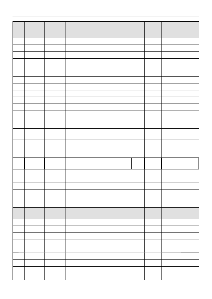
C-3 CANADA Channel CHART
CH SEND
(MHz)
RECEIVE
(MHz)
TRAFFIC TYPE SHIP
TO
SHIP
SHIP TO
SHORE
NAME TAG
01 156.050 160.650 Public Correspondence, Duplex No Yes TELEPHONE
02 156.100 160.700 Public Correspondence, Duplex No Yes TELEPHONE
03 156.150 160.750 Public Correspondence, Duplex No Yes TELEPHONE
04A 156.200 156.200 Canadian Coast Guard, SAR Yes Yes CANADIAN CG
05A 156.250 156.250 Port Operations, VTS in Selected
Areas
Yes Yes PORT OPS/VTS
06 156.300 156.300 Inter-ship Safety Yes No SAFETY
07A 156.350 156.350 Commercial Yes Yes COMMERCIAL
08 156.400 156.400 Commercial (inter-ship only) Yes No COMMERCIAL
09 156.450 156.450 Recreational Calling Channel Yes Yes CALLING
10 156.500 156.500 Commercial Yes Yes COMMERCIAL
11 156.550 156.550 Commercial, VTS in Selected Areas Yes Yes VTS
12 156.600 156.600 Port Operations, VTS in Selected
3
156.650 156.650 Intership Navigation Safety
13
14 156.700 156.700 Port Operations, VTS in Selected
1
15
156.750 156.750 Commercial – 1W Only Yes Yes COMMERCIAL
16 156.800 156.800 International Distress, Safety, and
1
156.850 156.850 State Controlled – 1W Only Yes Yes SAR
17
Areas
to-bridge) 1W with power-up
Areas
Calling
Yes Yes PORT OPS/VTS
(bridge-
Yes No BRIDGE COM
Yes Yes PORT OPS/VTS
Yes Yes DISTRESS
18A 156.900 156.900 Commercial Yes Yes COMMERCIAL
19A 156.950 156.950 Canadian Coast Guard Yes Yes CANADIAN CG
1
157.000 161.600 Canadian Coast Guard, Duplex– 1W
20
Only
No Yes CANADIAN CG
21 157.050 161.650 Port Operations, Duplex No Yes PORT OPS
21A 157.050 157.050 U.S. Government, Canadian Coast
Guard
Yes Ye s UNAUTHORIZED
21B RX Only 161.650 Port Operations, RX Only ------ ------ PORT OPS
22A 157.100 157.100 Canadian Coast Guard Liaison Yes Yes CANADIAN CG
23 157.150 161.750 Public Correspondence, Duplex No Yes TELEPHONE
24 157.200 161.800 Public Correspondence, Duplex No Yes TELEPHONE
25 157.250 161.850 Public Correspondence, Duplex No Yes TELEPHONE
25B RX Only 161.850 Public Correspondence, RX Only ------ ------ TELEPHONE
26 157.300 161.900 Public Correspondence, Duplex No Yes TELEPHONE
27 157.350 161.950 Public Correspondence, Duplex No Yes TELEPHONE
28 157.400 162.000 Public Correspondence, Duplex No Yes TELEPHONE
48 Northstar Explorer VHF Series: 721US, 721EU Operation and Installation Manual
Page 49
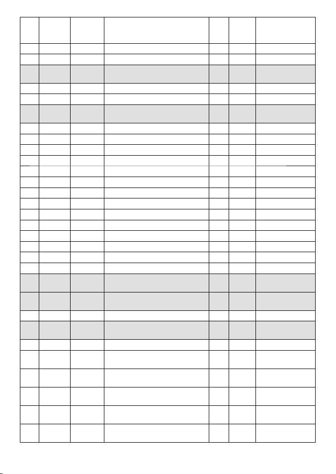
CH SEND
(MHz)
RECEIVE
(MHz)
TRAFFIC TYPE SHIP
TO
SHIP
SHIP TO
SHORE
NAME TAG
28B RX Only 162.000 Public Correspondence, RX Only ------ ------ TELEPHONE
60 156.025 160.625 Public Correspondence, Duplex No Yes TELEPHONE
4
156.075 156.075 U.S. Government, Canadian Coast
61A
Guard
Yes Yes UNAUTHORIZED
62A 156.125 156.125 Canadian Coast Guard Yes Yes CANADIAN CG
64 156.225 160.825 Public Correspondence, Duplex No Yes TELEPHONE
4
156.225 156.225 U.S. Government, Canadian
64A
Commercial Fishing
Yes Yes UNAUTHORIZED
65A 156.275 156.275 Port Operations Yes Yes PORT OPS
1
156.325 156.325 Port Operations – 1W Only Yes Yes PORT OPS
66A
67 156.375 156.375 Commercial, SAR Yes No COMMERCIAL
68 156.425 156.425 Boat Operations, Recreational Yes No SHIP - SHIP
69 156.475 156.475 Commercial Fishing Only Yes Yes COMMERCIAL
6
156.525 156.525 Digital Selective Calling - DSC ------ ------ DSC
70
71 156.575 156.575 Boat Operations, Recreational Yes Yes PLEASURE
72 156.625 156.625 Intership Yes No SHIP - SHIP
73 156.675 156.675 Commercial Fishing Only Yes Yes COMMERCIAL
74 156.725 156.725 Commercial Fishing Only Yes Yes COMMERCIAL
1
156.875 156.875 Port Operations –1W Only Yes Yes PORT OPS
77
78A 156.925 156.925 Boat Operations, Recreational Yes No SHIP - SHIP
79A 156.975 156.975 Commercial Yes Yes COMMERCIAL
80A 157.025 157.025 Commercial Yes Yes COMMERCIAL
4
157.075 157.075 U.S. GovernmENT or push the rotary
81A
4
157.125 157.125 U.S. Government, Canadian Coast
82A
knob Operations
Guard
Yes Yes UNAUTHORIZED
Yes Yes UNAUTHORIZED
83 157.175 161.775 Canadian Coast Guard Yes Yes CANADIAN CG
4
157.175 157.175 U.S. Government, Canadian Coast
83A
Guard
Yes Yes UNAUTHORIZED
83B RX Only 161.775 Canadian Coast Guard, RX Only ------ ------ CANADIAN CG
84 157.225 161.825 Public Correspondence, Marine
85 157.275 161.875 Public Correspondence, Marine
86 157.325 161.925 Public Correspondence, Marine
87 157.375 161.975 Public Correspondence, Marine
88 157.425 162.025 Public Correspondence, Marine
Operator
Operator
Operator
Operator
Operator
No Yes TELEPHONE
No Yes TELEPHONE
No Yes TELEPHONE
No Yes TELEPHONE
No Yes TELEPHONE
49Northstar Explorer VHF Series: 721US, 721EU Operation and Installation Manual
Page 50

WEATHER
MHz TRAFFIC TYPE NAME TAG
Wx01 RX Only 162.550 NOAA WEATHER CHANNEL ------ ------ NOAA WX
Wx02 RX Only 162.400 NOAA WEATHER CHANNEL ------ ------ NOAA WX
Wx03 RX Only 162.475 NOAA WEATHER CHANNEL ------ ------ NOAA WX
Wx04 RX Only 162.425 NOAA WEATHER CHANNEL ------ ------ NOAA WX
Wx05 RX Only 162.450 NOAA WEATHER CHANNEL ------ ------ NOAA WX
Wx06 RX Only 162.500 NOAA WEATHER CHANNEL ------ ------ NOAA WX
Wx07 RX Only 162.525 NOAA WEATHER CHANNEL ------ ------ NOAA WX
Wx08 RX Only 161.650 CANADIAN WEATHER CHANNEL ------ ------ CANADA WX
Wx09 RX Only 161.775 CANADIAN WEATHER CHANNEL ------ ------ CANADA WX
Wx10 RX Only 163.275 NOAA WEATHER CHANNEL ------ ------ NOAA WX
SPECIAL NOTES ON CANADA CHANNEL USAGE
1. LOW POWER (1 W) only.
2. Receive Only.
3. LOW POWER (1 W) initially. Override to HIGH POWER by holding down H/L key before transmitting. Used
normally in bridge-to-bridge communications.
4. Lightly Shaded Simplex channels 21A, 23A, 61A, 64A, 81A, 82A, and 83A cannot be lawfully used in
Canada waters unless special authorization is obtained from the Canadian Coast Guard. Not for use by
the general public.
5. The letter “A” illuminated by the channel number indicates the Canada channel is simplex. This same
channel is always duplex when selecting International. There is no “A” reference for International channels.
The letter “B” is only used for some Canadian “Receive Only” channels.
6. Channel 70 is designated for use exclusively for Digital Selective Calling (DSC), such as Distress, Safety,
and Ship Calls. No voice communication is allowed on CH70.
7. The CANADA mode is not legal to use in U.S. waters.
50 Northstar Explorer VHF Series: 721US, 721EU Operation and Installation Manual
Page 51
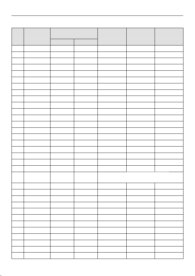
C-4 EU INLAND WATERWAY CHANNELS - Country Spec ific
For specifi c channel information for your country, please refer to local authorities.
CH SPECIFIC
FOOTNOTES
60 a) 156.025 160.625 x
1 a) 156.05 160.65 x
61 a) 156.075 160.675 x
2 a) 156.1 160.7 x
62 a) 156.125 160.725 x
3 a) 156.15 160.75 x
63 a) 156.175 160.775 x
4 a) 156.2 160.8 x
64 a) 156.225 160.825 x
5 a) 156.25 160.85 x
65 a) 156.275 160.875 x
6 a) b) 156.3 156.3 x
66 a) 156.325 160.925 x
7 a) 156.35 160.95 x
67 a) c) 156.375 156.375 x
8 a) q) 156.4 156.4 x
68 a) 156.425 156.425 x
9 a) b) c) 156.45 156.45 x
69 a) 156.475 156.475 x
10 e) 156.5 156.5 x
70 a) 156.525 156.525 Digital selective calling for distress,
11 156.55 156.55 x
71 156.575 156.575 x
12 156.6 156.6 x
72 a) r) 156.625 156.625 x
13 f ) 156.65 156.65 x
73 f ) g) 156.675 156.675 x
14 q) 156.7 156.7 x
74 a) 156.725 156.725 x
15 h) 156.75 156.75 x
75 o) 156.775 156.775 x
16 i) 156.8 156.8 x
76 j) d) o) 156.825 156.825 x
T
RANSMITTING
FREQUENCY (MHZ)
SHIP LAND
SHIP-TO-SHIP SHIP-TOPORT NAUT.INFORM
saftey and calling
51Northstar Explorer VHF Series: 721US, 721EU Operation and Installation Manual
Page 52

17 h) 156.85 156.85 x
77 a) k) 156.875 156.875 x
18 156.9 161.5 x
78 156.925 161.525 x
19 156.95 161.55 x
79 a) 156.975 161.575 x
20 157 161.6 x
80 157.025 161.625 x
21 a) 157.05 161.65 x
81 a) 157.075 161.675 x
22 157.1 161.7 x
82 l) m) 157.125 161.725 x
23 m) 157.15 161.75 x
83 a) m) 157.175 161.775 x
24 m) 157.2 161.8 x
84 m) 157.225 161.825 x
25 m) 157.25 161.85 x
85 a) m) 157.275 161.875 x
26 m) 157.3 161.9 x
86 a) m) 157.325 161.925 x
27 m) 157.35 161.95 x
87 a) d) 157.375 157.375 x
28 m) 157.4 162 x
88 a) p) 157.425 157.425 x
AIS 1 a) n) 161.975 161.975
AIS 2 a) n) 162.025 162.025
52 Northstar Explorer VHF Series: 721US, 721EU Operation and Installation Manual
Page 53

1.1 General remarks to frequency table 1
1.1.1 The channels for service categories ship-to-ship and nautical information may also be used for vessel
traffi c-sys tems by traffi c centres.
1.1.2 In some countries, frequencies certain channels are used for another service category or other radio services. These countries are Austria, Bulgaria, Croatia,, the Federal Republic of Yugosla via, Hun gary, Moldova,
Romania, the Russian Federation, the Slovak Republic, the Czech Republic (with exemption of channels
08, 09, 72, 74 and 86), Ukraine and the Federal Republic of Yugosla via. The Administra tions concerned
should make any possible attempt to make these fre quencies channels as soon as possible available for
the radiotelephone service on Inland Waterways and/or the required service catego ry.
1.2 Explanation of specifi c footnotes in frequency table 1
a. In the countries mentioned under 1.1.2, it is strictly prohibited to use this channel.
b. This channel is not allowed to be used between Rhine km 150 and km 350.
c. In the Netherlands, this channel is used by for its on-scene communi cations during safety operati ons
on the North Sea, IJsselmeer, Wadden zee, Ooster- and Wester schelde.
d. This channel may also be used for piloting, mooring, tugging and for other nautical purposes.
e. This channel is the fi rst ship-to-ship channel, unless the competent authority has designated another
channel.
In the countries mentioned under 1.1.2, it is allowed that the output power is set to a value between 6
and 25 W until 1 January 2005.
f. In the countries mentioned under 1.1.2, this channel is used for service category ship-to-port authori-
ties.
g. In the Netherlands, this channel is used by its national coastgu ard for communicati ons during oil pol-
lution operations on the North Sea and for safety messages for the North Sea, Wadden zee, IJsselmeer,
Ooster- and Westerschelde.
h. This channel may be used only for service category on-board on board communications.
i. This channel may be used only for communications between sea going vessels and participating land
stations in case of distress and safety communica ti ons within the maritime sea-areas.
In the countries mentioned under 1.1.2, this channel may be used only for distress, safety and calling.
j. The output power shall be reduced automatically to a value between 0.5 and 1 W.
k. This channel may be used for communications with a social charac ter.
l. I n the Netherlands and Belgium, this channel may be used for trans mit ting mes sages concerning bunker-
ing and victualling. The output power has to be reduced manually to a value between 0.5 and- 1 W.
m. This channel may also be used for public correspondence.
n. This channel will be used for an automatic ship identifi cation and surveillance sys tem (AIS) capable of
providing worldw ide operating on seas and Inland Waterways.
o. The availability of this channel is on a voluntary basis. All existing equipment shall be capable to of
operating on this channel within a ten-year period after the entry into force of this Arrangement.
p. After permission of the competent authority, this channel may be used only for spe cial events on a
temporary basis.
q. In the Czech Republic this channel is used for service category nautical information.
r. In the Czech Republic this channel is used for service category ship-to-port authorities.
53Northstar Explorer VHF Series: 721US, 721EU Operation and Installation Manual
Page 54

Appendix D - MMSID and License Information
You must obtain a user MMSID (Marine Mobile Service Identity) and enter it into your radio in order to use
the DSC functions. Contact the appropriate authorities in your country. If you’re unsure who to contact,
consult your Northstar dealer.
The user MMSID is a unique nine digit number, similar to a personal telephone number. It is used on marine
transceivers that are capable of using DSC (Digital Select Calling).
Depending upon your location, you may need a radio station license for the VHF 721. You may also need an
individual operator’s license.
Brunswick New Technologies Inc. recommends that you check the requirements of your national radio
communications authorities before operating DSC functions.
54 Northstar Explorer VHF Series: 721US, 721EU Operation and Installation Manual
Page 55

Section 7 - Install the Explorer 721
7-1 Installation Options
There are two ways to install the radio. You can choose:
• a deck or overhead mounted gimbal installation. The reversible mounting gimbal is fi xed to to a suitable
site and the radio is placed into it. The radio can be removed for storage and the viewing angle can be
adjusted.
• a recessed installation. The radio is recessed into a cavity cut into a bulkhead. The radio fi xture is permanent
and the viewing angle cannot be adjusted.
NOTE: An optional handset with a 9.8` (3 m) docking ca ble included can be purchased and connected to yo ur
Explorer 721 base unit to give second station op eration and intercom capability. The optional 701US handset
(for the Explorer 721US) and the optional 701EU handset (for the Explorer 721EU) are shown on the front cover.
7-2 Location Req uirements
Please check these BEFORE doing any cutting or drilling.
Whichever installation method you choose, ensure that the chosen location:
• is at least 3' (1 m) from the antenna
• allows easy connection to (at least) a 10 Amp fused 13.6 V DC electrical source and the antenna
• is at least 1.5' (45 cms) from the compass to avoid creating magnetic deviation of the compass during
radio operation
• has a suitable space close by for installing the microphone bulkhead mount
• provides easy access to the controls on the front panel
• provides reasonable access to the wiring at the back of the radio
• provides enough room to fi x the DSC warning label (721US only).
7-3 Checklist
The following items should be supplied in the box. Check before starting the installation and contact your
dealer if an item is missing.
NOTE: An antenna is NOT provided. Consult your Northstar dealer for advice if necessary.
1. Mounting gimbal for the VHF radio
2. Power supply cable with inbuilt 7 Amp fuse
3. External speaker connection cable with white (+) wire and black (-) wire
4. GPS connection cable
5. Two mounting knobs
6. Microphone bulkhead mount
7. Four self-tapping screws for the mounting gimbal
8. Four fl at screws for the mounting gimbal
9. Four spring washers for the mounting gimbal
10. Four plain washers for the mounting gimbal
11. Four nuts for the mounting gimbal
12. Two self-tapping screws for the microphone bulkhead mount
55Northstar Explorer VHF Series: 721US, 721EU Operation and Installation Manual
Page 56
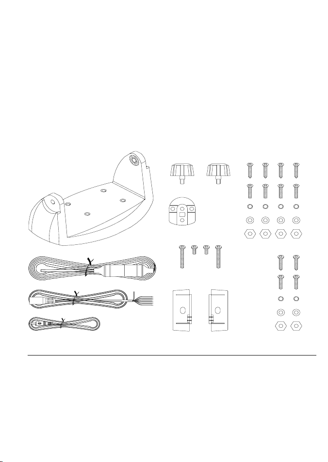
13. Two fl at screws for the microphone bulkhead mount
14. Two spring washers for the microphone bulkhead mount
15. Two plain washers for the microphone bulkhead mount
16. Two nuts for the microphone bulkhead mount
17. Two fl ush-mount brackets for recessed installation
18. Two M5x32 screws for recessedinstallation
19. Two M5x10 screws for recessed installation
20. Two plastic stoppers for the recessed installation (not pictured)
21. Installation template (not pictured)
22. One 7 Amp spare fuse (not pictured) in case of accidental reverse of battery polarity
23. Explorer 721 base unit and microphone (not pictured)
24. Explorer 721 protective cover (not pictured)
1
5
6
2
18 & 19
3
17
4
7-4 Gimbal Installation
1. Hold the mounting gimbal at the chosen location and use a soft pencil to mark the screw hole positions
onto the mounting surface.
2. If you can’t reach behind the mounting surface to attach the nuts, use the self-tapping screws instead
of the fl at screws shown in the picture. If you’re drilling into fi berglass, use a drill bit smaller than 3/16”
(5mm) to drill the pilot holes.
Other wise, drill the four screw holes where marked, using a 3/16” (5mm) drill bit. Drill completely through
the mounting surface.
3. Use a Philips screwdriver and the set of four fl at screws, spring washers, plain washers, and nuts to attach
the mounting gimbal to the location site.
56 Northstar Explorer VHF Series: 721US, 721EU Operation and Installation Manual
7
8
9
10
11
12
13
14
15
16
Page 57
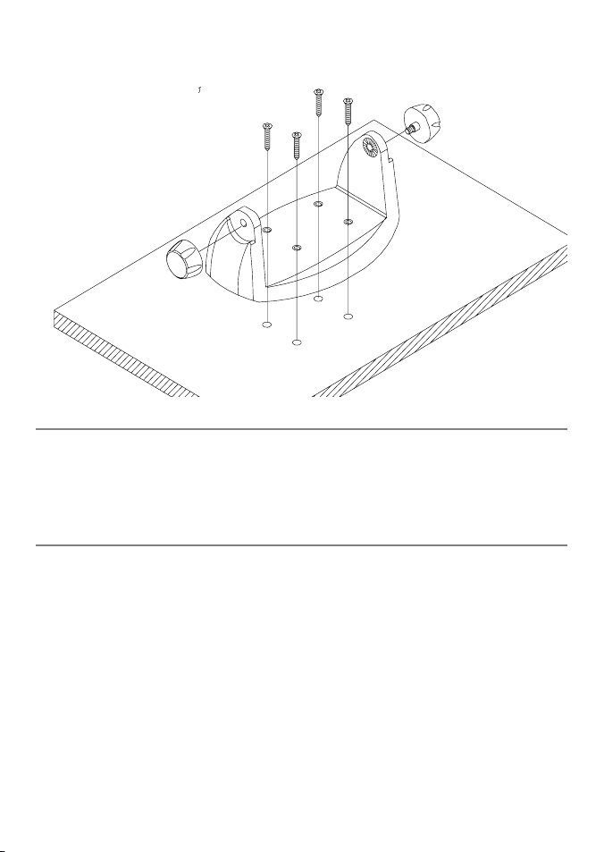
4. Slide the radio into the mounting gimbal.
5. Insert the two mounting k nobs through the holes and tighten them suffi ciently to hold the radio at the
desired viewing angle.
7-5 Change the Viewing Ang le
The viewing angle on the gimbal mount has a 20º tilt range. To change the current viewing angle on the
gimbal mount:
1. Support the radio, then cautiously loosen the mounting knobs until the radio can be moved.
2. Re-position the radio then tighten the mounting knobs again.
7-6 Recessed Installation
1. Tape the installation template onto the chosen location site.
2. Cut out the area marked by the solid dark line. (The dashed line indicates the total area that will be
covered by the radio fascia after installation.)
3. Remove the installation template and slide the radio into the cavity.
4. Working from the rear of the bulkhead, align the racheted outstand on each side of the radio with the
central hole in each mounting bracket.
5. Use the two short M5x10 screws to screw the mounting brackets to the sides of the radio.
6. Screw each M5x32 screw through the screw hole in the mounting bracket, then attach the stopper. If
your bulkhead exceeds 0.51” (13mm), the stopper can be discarded if necessary.
7. Tighten the M5x32 screws until the radio is held fi rmly against the rear of the bulkhead.
57Northstar Explorer VHF Series: 721US, 721EU Operation and Installation Manual
Page 58
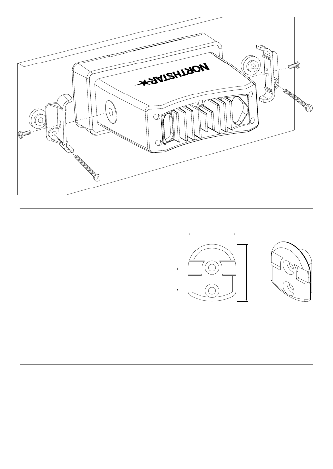
7-7 Install the Micropho ne Bulkhead Mount
1. Hold the microphone bulkhead mount at the
chosen location and use a soft pencil to mark
the screw hole positions on the mounting
MM
surface.
Ensure that the microphone curly cable will
comfortably reach this location BEFORE you drill.
2. Drill the two pilot screw holes where marked.
3. Use a short length Philips screwdriver and the
set of two fl at screws, spring washers, plain
washers, and nuts to secure the microphone
bulkhead mount at the location
site.
MM
MM
4. Hang the microphone on its mount.
NOTE: This mic clip has a special ma gnet glued in the rear of the clip to sense ON/OFF HOO K. Other mic
hangers cannot be used .
7-8 Connect the Radi o Cables
The connectors are on the rear of the base unit, as follows:
1. GPS connector. Plug the GPS cable jack into the connector. (If you’re not using this, be sure to put the
protective cap securely over the connector to protect it from moisture and dust.)
2. Docking Cable connector for optional Handset. Plug the docking cable jack into the connector. (If
you’re not using this, be sure to put the protective cap securely over the connector to protect it from
moisture and dust.)
3. External Speaker connector. Plug the external speaker cable jack into the connector BEFORE powering
on the radio. Use a 4 Ohm 4 Watt external speaker.
58 Northstar Explorer VHF Series: 721US, 721EU Operation and Installation Manual
Page 59
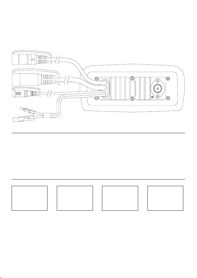
4. BLACK Power wire. Connect this to the NEGATIVE (-) battery terminal.
5. RED Power wire. Connect this to the POSITIVE (+) battery terminal. Check that a 10 Amp fuse is installed
on this power cable close to the battery.
6. ANT. A radio antenna is not supplied. A suitable radio antenna must be mounted and connected before
operating the Explorer 721 radio. Consult your dealer for advice if necessary.
7. GND. A ground connection is not usually required..
1
2
3
45
6
7
7-9 Set Up the Radio
IMPORTANT: You can’t make any DSC transmissions until you’ve obtained a user MMSID and entered it into your
Explorer 721.
The user MMSID is a unique nine digit number, similiar to a personal telephone number. It is used on
marine transceivers that are capable of using DSC (Digital Select Calling).
If you don’t have a user MMSID contact the appropriate authorities in your countr y. If you’re unsure who
to contact, consult your Nor thstar dealer.
7-10 Enter Your User MMSID
WARNING: This is a once- only operati on.
DSC SETUP
> USER MMSID
GROUP SE TUP
INDIV REPLY
1. Select DSC SETUP, then USER MMSID. A dashed line appears.
Enter your user MMSID along the dashed line. Press ENT or push the rotary knob to confi rm each correct
entry and to move to the next digit.
If you make an error, press CH - until < appears, then press ENT or push the rotary knob to backup and
correct the entry.
3. Press ENT or push the rotary knob to store your user MMSID.
4. Enter your user MMSID again as a password check, then press ENT or push the rotary k nob to permanently
store the user MMSID and return to the menu.
You can view your stored user MMSID at anytime by selecting USER MMSID in the main menu.
INPUT USER
MMSID
–––––––––
187654321
MMSID
> STORE
CANCEL
USER MMSID
INPUT AGAIN
–––––––––
59Northstar Explorer VHF Series: 721US, 721EU Operation and Installation Manual
Page 60
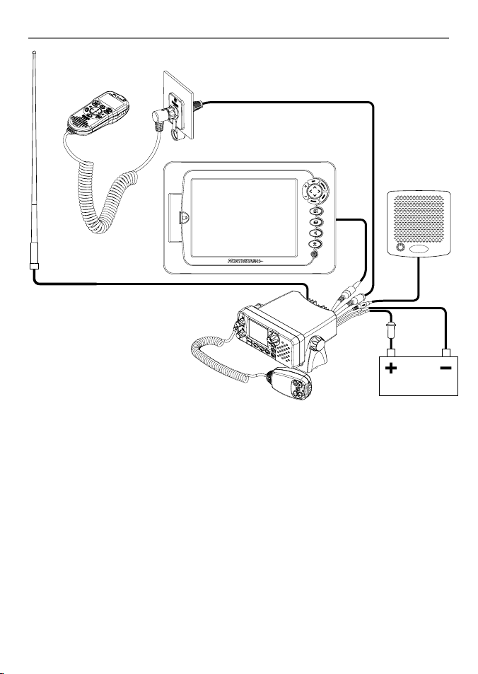
7-11 The Completed Installat ion (with Optional Hand set)
M84
Optional Handset
VHF Antenna
Antenna connection cable
Base unit with microphone
Wallplate on bulkhead
M84
Northstar GPS
product
Handset docking cable
Fuse on RED
power cable
External
speaker
External speaker
connection cable
BLACK
power
cable
Battery
60 Northstar Explorer VHF Series: 721US, 721EU Operation and Installation Manual
Page 61

UNITED STATES
30 Sudbury Road,
Acton, MA 01720,
United States
Ph: +1 978.897.6600
Fax: +1 978.897.7241
EUROPE
Unit 2, Ocean Quay,
Belvidere Rd, Southampton,
SO14 5QY, England
Ph: +44 2380 339922
Fax: +44 2380 330345
MN000751A-G
AUSTRALIA
PO Box 479,
Gladesville, NSW 2111,
Australia
Ph: +61 2 9879 9000
Fax: +61 2 9879 9001
www.northstarnav.com
NEW ZEALAND
PO Box 68 155,
Newton, Auckland,
New Zealand
Ph: +64 9 481 0500
Fax: +64 9 481 0590
Designed in New Zealand
Made in China
0560
 Loading...