

Page 1
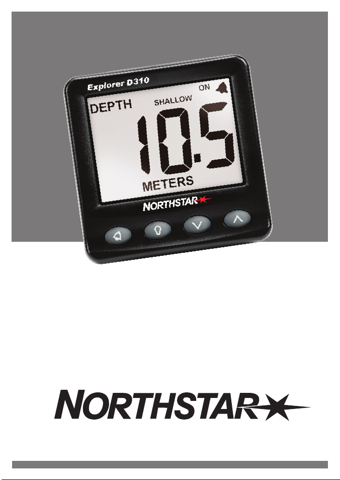
Explorer D310
Depth Instrument
Installation and Operation Manual
www.northstarnav.com
Page 2
IMPORTANT SAFETY INFORMATION
Please read carefully before installation and use.
This is the safety alert symbo l. It is used to aler t you to
potential personal injury hazards, Obey all safety messages that
follow this symbol to avoidpossible injury or death.
WARNING indicates a potentially hazardous situation which, if
not avoided, could result in death or serious injury
CAUTION indicates a potentially hazardous situation which, if
not avoided, could result in minor or moderate injury.
CAUTION used without the safety alert symbol indicates a
potentially hazardous situation which, if not avoided, may
result in property damage.
DISCLAIMER: It is the owner’s sole
responsibility to install and use the instrument
and transducers in a manner that will not cause
accidents, personal injur y or property damage.
The user of this product is solely responsible for
observing safe boating practices.
NAVICO HOLDING AS. AND ITS SUBSIDIARIES,
BRANCHES AND AFFILIATES DISCLAIM ALL
LIABILITY FOR ANY USE OF THIS PRODUCT IN A
WAY THAT MAY CAUSE ACCIDENTS, DAMAGE OR
THAT MAY VIOLATE THE LAW.
Governing Language: This statement,
any instruction manuals, user guides and
other information relating to the product
(Documentation) may be translated to, or
has been translated from, another language
(Translation). In the event of any conflict
between any Translation of the Documentation,
the English language version of the
Documentation will be the official version of the
Documentation.
This manual represents the Explorer D310 as at
the time of printing. Navico Holding AS. and its
subsidiaries, branches and affiliates reserve the
right to make changes to specifications without
notice.
Copyright © 2008 Navico Holding AS.
Northstar™ is a registered trademark of Navico
Holding AS.
FCC Statement
Note: This equipment has been tested and found to comply with the limits for a Class B digital device,
pursuant to Part 15 of the FCC Rules. These limits are designed to provide reasonable protection against
harmful interference in a normal installation. This equipment generates, uses and can radiate radio
frequency energy and, if not installed and used in accordance with the instructions, may cause harmful
interference to radio communications. However, there is no guarantee that interference will not occur in
a particular installation. If this equipment does cause harmful interference to radio or television reception,
which can be determined by turning the equipment off and on, the user is encouraged to try to correct
the interference by one or more of the following measures:
Reorient or relocate the receiving antenna.
Increase the separation between the equipment and receiver.
Connect the equipment into an output on a circuit different from that to which the receiver is
connected.
Consult the dealer or an experienced technician for help.
A shielded cable must be used when connecting a peripheral to the serial ports.
Page 3

Contents
1 Introduc tion .......................................................................................................................................... 4
2 Operati on ..............................................................................................................................................4
2-1 Turn on and off ...................................................................4
2-2 Basic operation ...................................................................4
2-3 Alarms ............................................................................5
2-4 Simulate mode ...................................................................5
2-5 Key reference .....................................................................5
3 Depth, keel o ffset, too dee p alarm, too shallow al arm ............................................. 6
3-1 Set depth units ...................................................................6
3-2 Set too deep alarm ...............................................................6
3-3 Set too shallow alarm .............................................................6
3-4 Anchor watch ....................................................................7
3-5 Set keel offset ....................................................................7
4 Systems of s everal instrument s ................................................................. 7
4-1 NavBus ...........................................................................7
5 Explor er D310 hardware ........................................................................ 8
5-1 What comes with your Explorer D310 .............................................8
5-2 Other parts required ..............................................................8
5-3 Transducer .......................................................................8
5-4 Accessories .......................................................................8
6 Install ation and setup. . . . . . . . . . . . . . . . . . . . . . . . . . . . . . . . . . . . . . . . . . . . . . . . . . . . . . . . . . . . . . . . . . . . . . . . . . 9
6-1 Installation .......................................................................9
6-2 Set up ...........................................................................10
6-3 Resetting to factory defaults ....................................................10
Appendi x A - Specificati ons ...................................................................... 11
Appendi x B - Troubles hooting ................................................................... 11
Units
The factory default units are metres. To change these units, please refer to section 3-1 of this manual.
Northstar Explo rer D310 Installation an d Operation Manual
3
Page 4
1 Introduction
The Explorer D310 measures and displays the depth
of the water. An installed Explorer D310 usually has
two parts:
The display unit.
A depth transducer, which is attached to the
hull and wired to the display unit.
The unit is powered from the boat’s power supply.
The Explorer D310 is part of the Northstar family of
instruments for boats, which includes instruments
for speed, depth, wind and repeaters. These
instruments can be connected together to form an
integrated data s ystem for a boat (see section 4).
For maximum benefit, please read this manual
carefully before installation and use.
How the transdu cer measures depth
The depth transducer generates an ultrasonic
(sound) pulse, which travels down through the
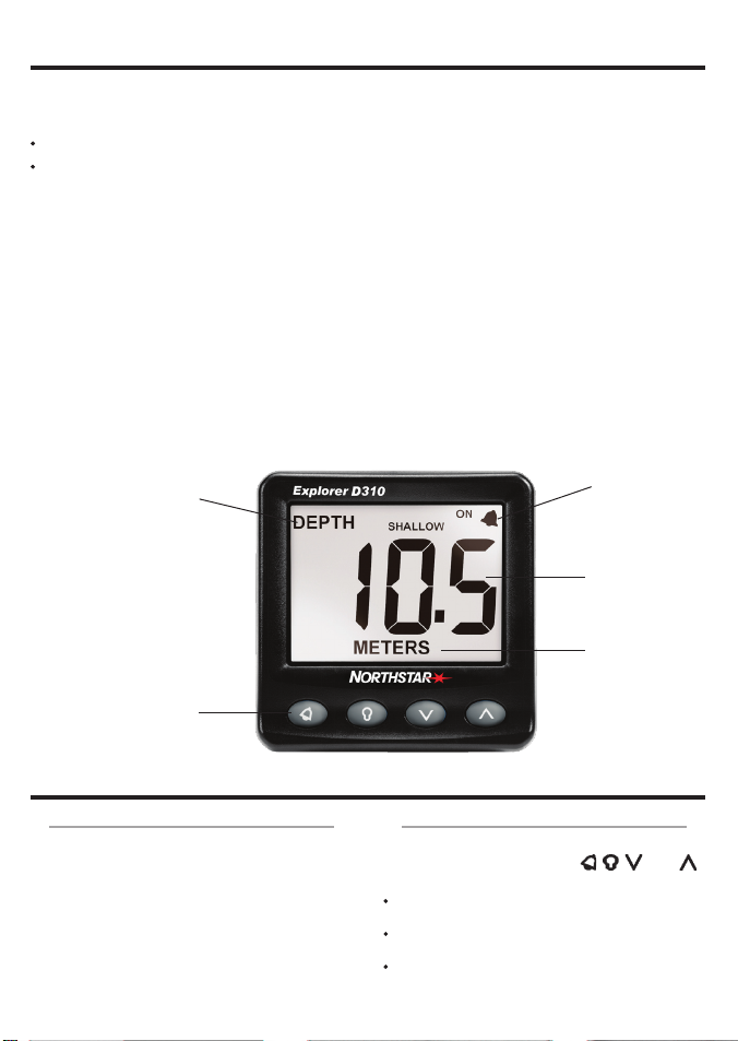
The Explo rer D310 display unit
Display
(backlit)
water. When the pulse meets the bottom, some of
the pulse is ref lected back up towards the boat and
is received by the transducer.
The display unit analyses the reflections from
each pulse. It removes unwanted reflections (from
bubbles and other objects) and calculates the
depth by measuring the time bet ween sending the
pulse and receiving its echo.
Cleaning a nd maintenance
Clean the display unit and any plastic transducers
with a damp cloth or mild detergent. Avoid abrasive
cleaners, petrol or other solvents.
When repainting the hull, cover or remove any
visible transducers. Depth transducers may be
coated with a thin layer of antifouling paint; gently
sand off any previous paint first.
Alarm symbol
Display normally
shows depth
Depth units
Four keys
(backlit)
2 Operation
2-1 Turn on and of f
Turn the unit on and of f with the auxiliary power
switch on the boat. The unit does not have its own
power switch. When you turn it off, any settings
you have made are retained.
If the word SIMULATE flashes at the top, left of the
display, then the unit is in simulate mode (see section
2-4).
4
Northstar Explo rer D310 Installation an d Operation Manual
111 x 111 mm
(4.4” x 4.4”)
2-2 Basic operation
The keys
The unit has four keys, labelled and
. In this manual:
Press means to push the key for less than one
second.
Hold for two seconds means to hold the key
down for two seconds or more.
Press one key + another key means to push
both keys together.
Page 5
Set backlig ht for screen and keys
You can set the backlight to one of four brightness
levels or off. Press
backlight level, press
once to display the current
again to change the level:
Backlight
level 2
The display
The display normally shows depth. If it displays
dashes (— —) then it means that the depth is too
deep or unknown.
2-5 Key reference
2-3 Alarms
The Explorer D310 can be set to sound an alarm
when the water is too deep or too shallow (see
sections 3-2 and 3-3). When the alarm sounds,
the internal beeper sounds, the
display flashes and any external beepers or lights
operate.
Press to mute the alarm. The alarm stays muted
until the depth becomes normal. The alarm will
sound if the depth becomes too deep or too
shallow again.
symbol on the
2-4 Simulate mo de
Simulate mode allows you to become familiar
with the unit off the water. In Simulate mode,
the Explorer D310 functions normally except the
transducer is ignored and the unit generates this
data internally. The word SIMULATE flashes at the
top, left corner of the screen.
To turn Simulate mode on or off:
1 Turn the power off.
2 Hold down
while you turn the power on.
Turn power on
Hold
Hold
+
5 sec
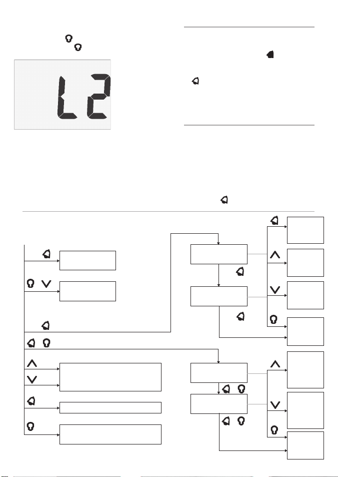
Normal ope ration
Hold
2 sec
+
Turn Simulate
on or off
Reset memory
Change depth units (metres, feet
or fathoms)
Mute an alarm
Adjust backlight
(4 levels or off )
Northstar Explo rer D310 Installation an d Operation Manual
Set alarm s
Set Too Deep
alarm
Set Too Shallow
alarm
Setup
Set Keel Of fset
Set Backlight
Group
Hold
2 sec
Hold
2 sec
+
+
Turn alarm
on or off
Increase
alarm
depth
Decrease
alarm
depth
Return to
normal
operation
Increase
value or
change
setting
Decrease
value or
change
setting
Return to
normal
operation
5
Page 6
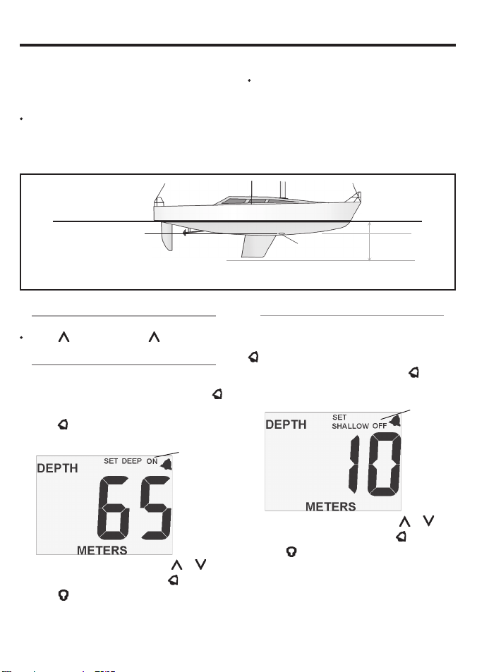
3 Depth, keel offset, too deep alarm, too shallow alarm
Depth and ke el offset
The displayed depth is the distance from the
transducer on the boat to the bot tom of the water,
plus or minus an of fset which is called the keel
offset:
A posit ive keel offset displays depth as
measured from a point above the transducer.
For example, if you set the offset to the distance
from the transducer to the surface, it will display
Keel off set
Water surface
Depth of transducer
Note: The b oat illustrated uses a through hu ll transducer
the depth from the surface to the bottom of
the water.
A negative keel of fset displays depth as
measured from a point below the transducer.
For example, if you set the of fset to minus the
distance from the transducer to the bottom
of the keel, it will display the depth from the
bottom of the keel to the bottom of the water.
Keel offset
Positive value
Tra nsd uce r
Negative value
3-1 Set depth units
The units can be METERS, FEET or FATH:
Press ; if necessary, press again.
3-2 Set too deep alarm
The too deep alarm sounds if the alarm is turned on
and the depth becomes equal to or more than the
too deep alarm depth. To mute the alarm, press
To set the too deep alarm:
1 Hold
2 To change the alarm depth, press or .
3 To turn the alarm on or off, press
4 Press .
6
for two seconds to display the Too
Deep Alarm screen:
Alarm
is on
Deep
alarm
value
.
Northstar Explo rer D310 Installation an d Operation Manual
3-3 Set too shallow al arm
The too shallow alarm sounds if the alarm is turned
on and the depth becomes equal to or less than the
too shallow alarm depth. To mute the alarm, press
. To set the too shallow alarm:
1 At the Too Deep Alarm screen, hold for
two seconds to display the Too Shallow Alarm
.
screen:
2 To change the alarm depth, press or .
3 To turn the alarm on or off, press .
4 Press .
Alarm
is off
Shallow
alarm
value
Page 7
3-4 Anchor watch
To set an anchor watch, set the too shallow alarm to
slightly less than the current depth and set the too deep
alarm to slightly more than the current depth. Allow for
tide changes.
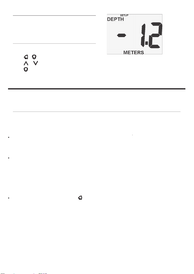
Keel offset
(negative)
3-5 Set keel off set
Keel offset is described above. The range is ± 2.9 m (± 9.6
ft, ± 1.6 fathoms):
1 Press + to display the Keel Offset screen.
2 Press or to change the keel offset.
3 Press .
4 Systems of several instruments
Several Nor thstar instruments can be connected together to share data. There are t wo ways of connecting
instruments together, NavBus or NMEA.
4-1 NavBus
NavBus is a Northstar proprietary system that allows
systems of multiple instruments to be built using
a single set of transducers. When instruments are
connected by NavBus:
If you change the units, alarms or calibration
in one instrument, then the values will
automatically change in all other instruments of
the same type
Each instrument can be assigned to a group
of instruments (see section 6-2, step 2). If
you change the backlight in an instrument
in group 1, 2, 3 or 4 then the backlight will
automatically change in the other instruments
in the same group. If you change the backlight
in an instrument in group 0 then no other
instruments are affected.
If an alarm sounds, mute it by pressing
any instrument which can display that alarm.
on
NavBus and t he Explorer D310
If the Explorer D310 does not have a depth
transducer fitted then the unit will automatically
take depth readings from another instrument,
via NavBus, if the data is available. For more
information, refer to the NavBus Installation and
Operation manual.
Note: If a transducer is not fitted to the unit and the
corresponding external data is not available then
the displayed value will be dashes (— —).
4-2 NMEA
NMEA is an industry standard, but is not as flexible
as NavBus as it requires dedicated connections
between instruments. Depth data is output by the
Explorer D310 and can be read and displayed by the
Northstar Explorer R310 or other NMEA instrument.
Northstar Explo rer D310 Installation an d Operation Manual
7
Page 8
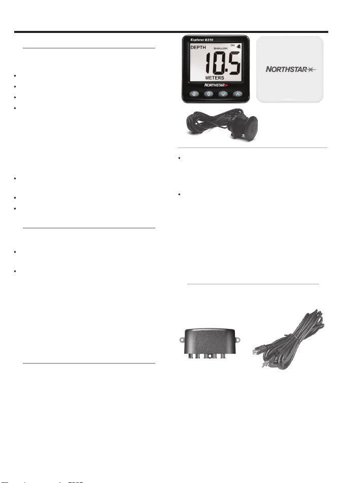
5 Explorer D310 hardware
5-1 What comes with your Ex plorer D310
The Explorer D310 comes in several configurations.
Standalo ne configuration
Explorer D310 unit with protec tive cover.
Warranty card.
Mounting template.
This Installation and Operation manual.
In addition, the standalone configuration usually
requires a depth transducer (see section 5-3).
Kit configu ration
The Explorer D310 is available in several kit
configurations with different grades of through hull
transducer, with:
The parts for the standalone configuration,
listed above.
Through hull depth transducer.
Transducer Installation manual.
5-2 Other parts re quired
One or more 310 series instruments will be
connected to the boat 12 V power supply via:
An accessory switch to turn the instruments on
and off.
A fuse. Use a 1 A fuse for between one and five
instruments.
Optional ex ternal beepers or lights can be fitted.
The Explorer D310 output is switched to ground,
30 V DC and 250 mA maximum. If the beepers and
lights require more than 250 mA, fit a relay.
For systems of several instruments, wiring and
connectors are required (see section 4 or the
NavBus Installation and Operation manual).
5-3 Transducer
The Explorer D310 is usually used with a through
hull depth transducer. However, the unit can take
readings from another instrument, in which case it
may not need a transducer (see section 4).
A through hull transducer generally gives the
best per formance and is the best choice for
displacement hulls. It is mounted in a hole drilled
through the bottom of the boat.
A plastic through hull transducer is suitable
for GRP or metal hulls. Plastic through hull
transducers are not suitable for solid wooden
hulls (use Northstar’s bronze transducers).
A bronze transducer is suitable for wood
or fibreglass hulls. Never install a bronze
transducer in a metal hull, because it will cause
electrolytic corrosion.
A range of Northstar through hull transducers
are available, plus in hull and transom mount
transducers. For more information, refer to the
Transducer Installation manual or consult your
Northstar dealer.
5-4 Accessorie s
These accessories are available from your Northstar
dea ler.
NavBus junction box
(See section 4)
4 m (13 ft) depth
transducer extension
cable
8
Northstar Explo rer D310 Installation an d Operation Manual
Page 9
CAUTION
!
!
CAUTION
DANGER
WARNING
6 Installation and setup
Correct installation is critical to the per formance of
the unit. It is vital to read this section of the manual
and the documentation that comes with the other
parts before star ting installation.
The Explorer D310 can:
Drive external beepers or lights for the alarm.
Send and receive data from other Northstar
instruments connected via NavBus. Set tings for
alarms, units, calibration and backlighting are
shared (see section 4-1).
Send and receive NMEA data from other
instruments (see section 4-2).
The unit is waterproof from the front. Protect
the rear of the unit from water, or else water
might enter the breathing hole and damage
the unit. The warranty does not cover damage
caused by moisture or water entering the back
of the unit.
Ensure that any holes that you cut will not
weaken the boat ’s structure. If in doubt, consult
a qualified b oat builder.
The choice, location, angle and installation
of the transducers is the most critical
part of the installation. If they are not
correct, the unit can not perform at its
designed potential. If in doubt, consult
your Northstar dealer. Plastic through
hull transducers are usually unsuitable for
wood hulls. If in doubt, consult a marine
surveyor or marine engineer.
6-1 Installation
Explore r D310 display unit
1 Choose a location for the display unit that is:
Easily seen and protected from damage.
At least 100 mm (4”) from a compass and at
least 500 mm (1.65 ft) from a radio or radar
antenna.
Away from engines, fluorescent lights, and
power inverters.
Accessable from behind; the minimum
clearance required at the back is 50 mm (2”)
(see mounting diagram).
With the back of the unit protected from
moisture.
Northstar Explo rer D310 Installation an d Operation Manual
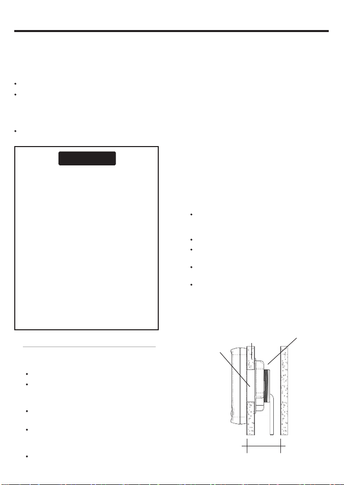
2 The unit must mount on a flat panel which
is less than 20 mm (0.75”) thick . Stick the
mounting template in place. Drill a 50 mm
(2”) fixing hole through the centre hole in the
template. Note that the template allows space
around the unit for the protective cover.
3 Remove the fixing nut from the back of the
unit. Inser t the stud at the back of the unit
through the mounting hole. Hand tighten the
fixing nut.
Transducers
1 If the Explorer D310 does not come with a
transducer, choose a suitable transducer (see
section 5-3). If the Explorer D310 is supplied
with a transducer, see section 5-3 to ensure that
it is suitable.
2 Choose a suitable location for the transducer
and install it by following the instructions in the
Transducer Installation manual.
3 Fit the cables between the transducer and the
display unit:
Keep the cable away from other cables,
engines, f luorescent lights, power inverters
and radio or radar transmit ters.
Ensure no connectors lay in the bilge.
If necessary, extend the cable by adding
extension cables.
Do not cut the cable on any depth
tra nsduc er.
Secure the cable at regular intervals.
4 Connect the transducer to the display unit
con necto r.
Side view o f display unit mo unting
Fixing hole
50 mm (2”)
Display
unit
20 mm (0.75”)
maximum thickness
Cables
Clearance 50 mm (2”) minimum
Fixing nut
9
Page 10
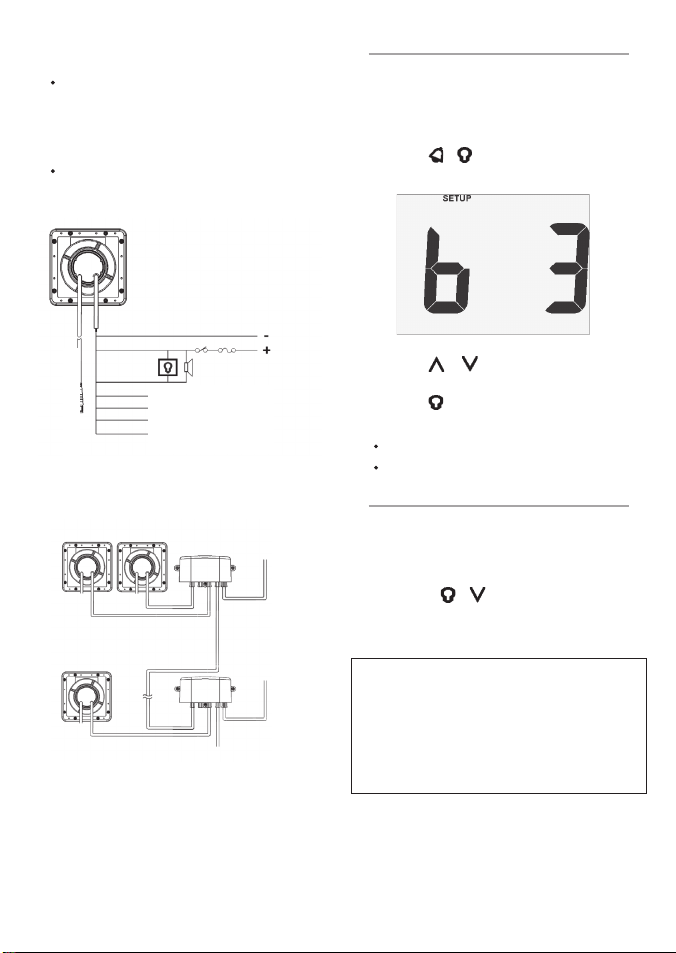
Power/data wiring
1 Wire the display unit power/data cable:
The unit requires 12 V DC power. Fit a
power switch and fuse to the power supply
or power the unit from a fused auxiliary
switch. The fuse should be 1 A for up to five
instruments.
If the external beepers and lights require
more than 250 mA DC total, fit a relay.
A single unit can be wired as shown below:
6-2 Set up
1 Take the boat for a trial run to check that all the
instruments work correc tly.
2 If the unit is part of a system of 310 series
instruments connected by NavBus, set the
backlight group number (see section 4-1):
i Press
+ several times until the
Backlight Group screen is displayed:
Backlight
group 3
Black
Red
Green
Yel low
White
Orange
Blue
Depth
With several instruments, use the optional
junction boxes to simplify wiring, as shown
below:
Switch Fuse
External beepers or
No connection
NMEA out
}
NavBus (optional)
12 V DC
Group 1
Junction
Power/data cables
Group 2
Power/data cable
For information on how to connect NavBus
and to use junction boxes, refer to the NavBus
Installation and Operation manual.
2 Tape or cover any unused wires or connectors
to protect them from water and keep them
from shorting together.
NavBus cable
Power & data
connections
Junction box
Power & data
connections
ii Press
iii Press .
3 Set:
The depth units (see section 3-1).
The keel offset (see section 3-5).
or to set the backlight group
number.
6-3 Resettin g to factory defaults
All settings may be reset to the manufacturer’s
default settings (see below).
To reset to factory defaults:
1 Turn the power off.
2 Hold down
on and continue to hold the keys down for at
least five seconds.
Depth units m
Keel of fset 0
Depth al arms Of f
SIMULATE mode Off
Backli ght level 0
Backli ght group 1
+ while you turn the power
10
Northstar Explo rer D310 Installation an d Operation Manual
Page 11

Appendix A - Specifications Appendix B - Troubleshooting
Physical
Case size 111 mm (4.4”) square.
LCD display 82 mm (3.2” ) wide, 61 mm (2.4”) high;
twisted nematic.
LCD digits 38 mm (1.4”) high.
Four operator keys, laser etched.
Backlighting for display and keys, amber, four
levels and of f.
Operating temperature 0 to 50°C (32 to 122°F).
Transducer cable length 8 or 9 metres (26.25 or
29.5 ft).
Power Cable length 1 m (3.25 f t).
Electrical
Power supply 10.5 to 16.5 V DC, 30 mA without
backlighting, 190 mA with full backlighting and
tra nsduc er.
External beeper or light output, switched to
ground, 30 V DC and 250 mA maximum.
Depth
Range 0.5 to 130 m (1.5 to 400 ft, 0.3 to 67 fa).
Typical accuracy < 2% (depends on type of
depth transducer, installation and water clarity).
Displays 0.0 to 19.9, 20 up.
Adjustable keel offset ± 2.9 m (± 9.6 ft, ± 1.6 fa).
Too deep and too shallow alarms (run both at
once to provide anchor watch facility).
Interfaces
NavBus connection to other Northstar
instruments.
NMEA 0183 outputs: DBT, DPT, PTTKD.
Standards compliance
EMC comp liance
USA (FCC): Part 15 Class B.
Europe (CE): EN50081-1, EN50082-1.
New Zealand and Australia (C Tick):
AS-NZS 3548.
Environment: IP66 from front when correctly
mounted.
Power/data ca ble wires
Wire Signal
Red Power positive, 12 V DC, 190 mA maximum
Black Power negative, NMEA common
Green External beeper or light out, switched to
ground, 30 V DC and 250 mA max.
Orange NavBus +
Blue NavBus White NMEA out
Yellow No connection
Northstar Explo rer D310 Installation an d Operation Manual
This troubleshooting guide assumes that you have
read and understood this manual.
It is possible in many cases to solve difficulties
without having to send the unit back to the
manufacturer for repair. Please follow this
troubleshooting section before contacting the
nearest Northstar dealer.
There are no user serviceable parts. Specialized
methods and testing equipment are required to
ensure that the unit is reassembled correctly and is
waterproof. Repairs to the unit must only be carried
out by a service centre approved by Northstar.
Users who ser vice the unit themselves will void the
warranty.
More information can be found on our website:
www.Northstarnav.com
1 Unit will not turn on:
a Fuse blown or circuit breaker tripped.
b Bat tery voltage is outside the range 10.5 to
16.5 V DC.
c Power/data cable damaged.
2 Depth reading wrong or erratic:
a Unit temporarily unable to detect bottom,
for example water too deep or too shallow,
water not clear, boat reversing and
transducer in turbulent water.
b Depth transducer cable unplugged or
damaged.
c Depth transducer fouled or damaged.
Check for fouling, damage or too thick a
layer of paint over it.
d Depth transducer installed incorrectly or
transducer does not have a smooth flow of
clear water over it. Review installation.
e Interference from the ultrasound pulse
from another depth sounder.
f Interference from electrical noise. Review
installation.
To check the transducer, disconnect it and
connect a known good transducer temporarily.
Hold it over the side of the boat in the water
and check if the unit displays a depth.
3 The word SIMULATE flashes at top, left of
screen, values displayed are unexpected:
a Unit is in simulate mode (see section 2-4).
4 The display fogs:
a Moist air has entered the breathing tube at
the rear of the unit. Air the boat or run unit
with backlight fully on.
b Water has entered the breathing tube.
Return unit for service.
11
Page 12

FOR FURTHER CONTACT DETAILS GO TO:
www.navico.com
Made in New Zealand
MN000626B-G
 Loading...