

Page 1
Explorer F210
Fuel Instrument
Installation and Operation Manual
www.northstarnav.com
Page 2

Northstar Explorer F210 Installation and Operation Manual2
Page 3
DANGER
!
WARNING
!
CAUTION
IMPORTANT SAFETY INFORMATION
Please read carefully before installation and use.
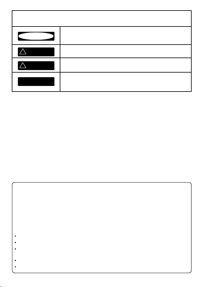
This is the safety alert symbol. It is used to alert you to potential personal
injury hazards, Obey all safety messages that follow this symbol to avoid
possible injury or death.
WARNING indicates a potentially hazardous situation which, if not avoided,
could result in death or serious injury
CAUTION indicates a potentially hazardous situation which, if not avoided,
could result in minor or moderate injury.
CAUTION
DISCLAIMER: It is the owner’s sole
responsibility to install and use the instrument
and transducers in a manner that will not cause
accidents, personal injury or property damage.
The user of this product is solely responsible for
observing safe boating practices.
BRUNSWICK NEW TECHNOLOGIES INC. AND ITS
SUBSIDIARIES AND AFFILIATES DISCLAIM ALL
LIABILIT Y FOR ANY USE OF THIS PRODUCT IN A
WAY THAT MAY CAUSE ACCIDENTS, DAMAGE OR
THAT MAY VIOLATE THE LAW.
Governing Language: This statement,
any instruction manuals, user guides and
other information relating to the product
(Documentation) may be translated to, or
CAUTION used without the safety alert symbol indicates a potentially hazardous situation which, if not avoided, may result in property damage.
has been translated from, another language
(Translation). In the event of any conf lict
between any Translation of the Documentation,
the English language version of the
Documentation will be the official version of the
Documentation.
This manual represents the Explorer F210
as at the time of printing. Brunswick New
Technologies Inc. and its subsidiaries and
affiliates reserve the right to make changes to
specifications without notice.
Copyright © 2006 Brunswick New Technologies
Inc. Northstar™ is a registered trademark of
Brunswick New Technologies Inc
FCC Statement
Note: This equipment has been tested and found to comply with the limits for a Class B digital device,
pursuant to Part 15 of the FCC Rules. These limits are designed to provide reasonable protection
against harmful interference in a normal installation. This equipment generates, uses and can radiate
radio frequency energy and, if not installed and used in accordance with the instructions, may cause
harmful interference to radio communications. However, there is no guarantee that interference
will not occur in a particular installation. If this equipment does cause harmful interference to radio
or television reception, which can be determined by turning the equipment off and on, the user is
encouraged to try to correct the interference by one or more of the following measures:
Reorient or relocate the receiving antenna.
Increase the separation between the equipment and receiver.
Connect the equipment into an output on a circuit different from that to which the receiver is
connected.
Consult the dealer or an experienced technician for help.
A shielded cable must be used when connecting a peripheral to the serial ports.
Northstar Explorer F210 Installation and Operation Manual 3
Page 4

Contents
1 Operati on ..............................................................................................................................................5
Fuel Flow . . . . . . . . . . . . . . . . . . . . . . . . . . . . . . . . . . . . . . . . . . . . . . . . . . . . . . . . . . . . . . . . . . . . . . . . . . . . . 5
Other Fuel Functions . . . . . . . . . . . . . . . . . . . . . . . . . . . . . . . . . . . . . . . . . . . . . . . . . . . . . . . . . . . . . . . . . 5
Changing the fuel remaining value . . . . . . . . . . . . . . . . . . . . . . . . . . . . . . . . . . . . . . . . . . . . . . . . . . . 5
Setting the low fuel alarm . . . . . . . . . . . . . . . . . . . . . . . . . . . . . . . . . . . . . . . . . . . . . . . . . . . . . . . . . . . . 6
Alarm activation . . . . . . . . . . . . . . . . . . . . . . . . . . . . . . . . . . . . . . . . . . . . . . . . . . . . . . . . . . . . . . . . . . . . . 6
Resetting the TRIP LOG or the TOTAL LOG . . . . . . . . . . . . . . . . . . . . . . . . . . . . . . . . . . . . . . . . . . . . 6
2 Instru ment Setup .................................................................................................................................. 7
Selecting units of measure . . . . . . . . . . . . . . . . . . . . . . . . . . . . . . . . . . . . . . . . . . . . . . . . . . . . . . . . . . . 7
Calibration . . . . . . . . . . . . . . . . . . . . . . . . . . . . . . . . . . . . . . . . . . . . . . . . . . . . . . . . . . . . . . . . . . . . . . . . . . . 7
3 Instal lation ............................................................................................................................................ 8
Location . . . . . . . . . . . . . . . . . . . . . . . . . . . . . . . . . . . . . . . . . . . . . . . . . . . . . . . . . . . . . . . . . . . . . . . . . . . . . 8
Mounting . . . . . . . . . . . . . . . . . . . . . . . . . . . . . . . . . . . . . . . . . . . . . . . . . . . . . . . . . . . . . . . . . . . . . . . . . . . . 8
Wiring Connection . . . . . . . . . . . . . . . . . . . . . . . . . . . . . . . . . . . . . . . . . . . . . . . . . . . . . . . . . . . . . . . . . . . 9
Installation of the fuel flow transducer . . . . . . . . . . . . . . . . . . . . . . . . . . . . . . . . . . . . . . . . . . . . . . . 9
Append ix A - Specifica tions ..................................................................................................................... 10
Append ix B - Troubleshooting C hart ........................................................................................................ 11
Northstar Explorer F210 Installation and Operation Manual4
Page 5
#
1 Operation
Fuel Fl ow
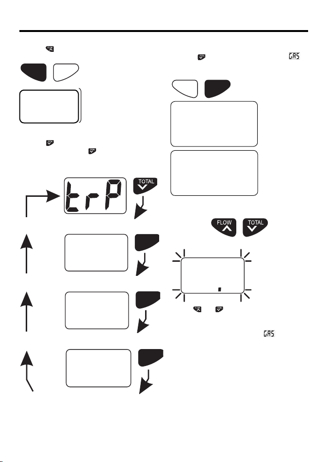
Press the key to display the current fuel flow
rate.
TOTALFLOW
^
V
86.8
Changing the fuel remaining value
To change the value of fuel remaining in the tank,
press the key until the display indicates
for two seconds and then displays the current
value.
TOTALFLOW
^
V
Other Fuel Functions
Press the key to cycle through the possible
functions. Each time the key is pressed the
display will show an identifier for 2 seconds
before the value is displayed.
Fuel used on trip
V
tOt
Fuel used in total
ALr
Low fuel alarm setting
GAS
Fuel remaining in tank
TOTAL
TOTAL
V
TOTAL
V
GAS
26.0
Press and hold both keys for three seconds and
the displayed value will begin to flash.
Press and hold for 3 seconds
260
Use the and keys to change the value.
Press and hold both keys for one second to
save this new value to memory and to exit this
function. The display will indicate and then
the new value.
Northstar Explorer F210 Installation and Operation Manual 5
Page 6
Setting th e low fuel alarm
#
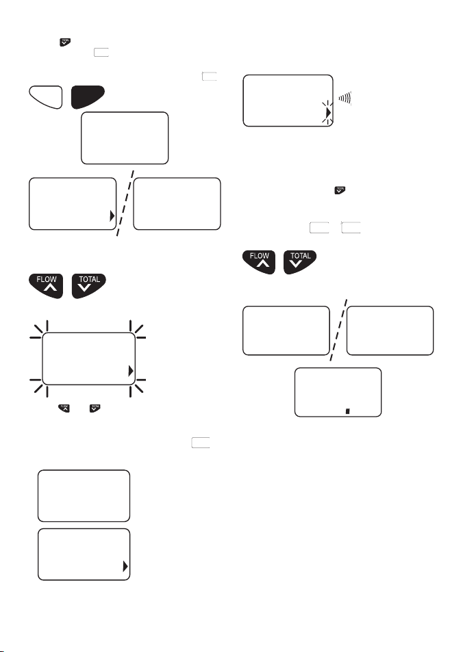
Use the key to select the alarm function. The
LCD will indicate
then display the present alarm value. If no alarm
value has been entered the LCD will indicate
^
ALr
for two seconds and will
TOTALFLOW
V
0FF
ALr
012 0FF
Press and hold both keys for three seconds and
the displayed value will begin to flash.
Press and hold for 3 seconds
812
Alarm activation
If the fuel remaining value drops below the fuel
alarm value, the alarm will sound and the alarm
arrow will flash.
.
trP
#
or
tOt
for 2 seconds
12
Press any key to mute the alarm. The alarm
arrow will continue to flash as long as the alarm
condition remains.
Resetti ng the TRIP LOG or the TOTAL LOG
To reset a log, press the key until the display
indicates the name of the log to be reset.
Press and hold both keys for three seconds.
Display will show
before resetting to zero.
Press and hold for 3 seconds
trP tOt
Use the and keys to select the desired
alarm value. Press and hold both keys for one
second to save this new value to memory and to
exit this function. The display will indicate
and then the new value.
ALr
ALr
814
The arrow pointing at the alarm bell will be
activated.
Northstar Explorer F210 Installation and Operation Manual6
000
The trip log value may be reset without changing
the total log value.
If the total log is reset to zero, then the trip log
will automatically reset to zero.
Note: If the total log exceeds 999 then both it
and the trip log will be reset to zero.
Page 7
2 Instrument Setup
Selecti ng units of measure
The Explorer F210 will indicate fuel values in
Litres, Imperial gallons or US gallons. To change
the current set ting perform the following steps:
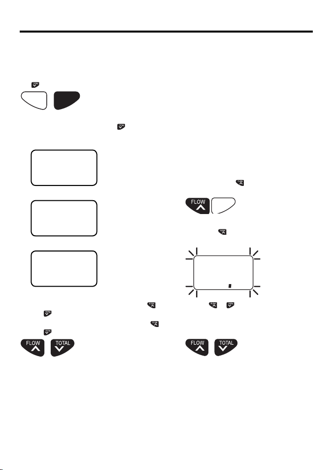
1. Power up the unit while holding down the
key.
TOTALFLOW
^
V
Hold down during power up
2. When the unit is on, release the
display will indicate the current display unit
with:
8U1
Imperial Gallons
8U2
US Gallons
8U3
Litres
3. To select the display unit desired, use the
and keys to change the value.
4. To exit this mode, press and hold both the
and keys simultaneously for one second.
key. The
Calib ration
The fuel transducer supplied with the fuel flow
meter will provide readings at bet ter than 5%
accuracy. Individual calibration will increase this
level of accuracy to better than 2% over a fuel
flow range of 10.0 to 120 litres per hour. Use the
following steps to calibrate your fuel flow meter:
1. Reset the total log value to zero (see previous
page).
2. Use a known amount of fuel. The larger the
amount the more accurate the calibration will
be.
3. Take note of the actual volume of fuel used
and the fuel used indicated by the total log. If
these two totals are different the instrument
may require calibration.
4. Press and hold the
power
Hold down during power up
5. Release the
total log value.
key while applying
FLOW
^
key. Display will flash current
260
6. Use the or keys to make the display
indicate the ac tual volume of fuel used.
7. Press both keys simultaneously for 1 sec to
exit.
Press and hold to exit
Information will now be indicated in the selected
display unit.
Northstar Explorer F210 Installation and Operation Manual 7
Press and hold for 1 second
The fuel f low meter is now calibrated.
Page 8
3 Installation
WARNING
IT IS VERY IMPORTANT TO INSTALL A FUEL FILTER BETWEEN THE FUEL FLOW TRANSDUCER
AND THE FUEL TANK. THIS FILTER WILL CATCH LARGER PARTICLES OF DIRT FROM THE
FUEL TANK AND PREVENT THE FINE GAUZE FILTER IN THE FUEL FLOW TRANSDUCER FROM
BECOMING BLOCKED AS THIS MAY DAMAGE THE ENGINE.
Location
The Explorer F210 is designed for above or below
deck installation. Select a position that is:
• On a flat surface
• At least 300mm (12”) from a compass
• At least 500mm (20”) from any radio
• Easy to read by the helmsman and crew
• Protected from physical damage
• Accessible to electrical cable connections
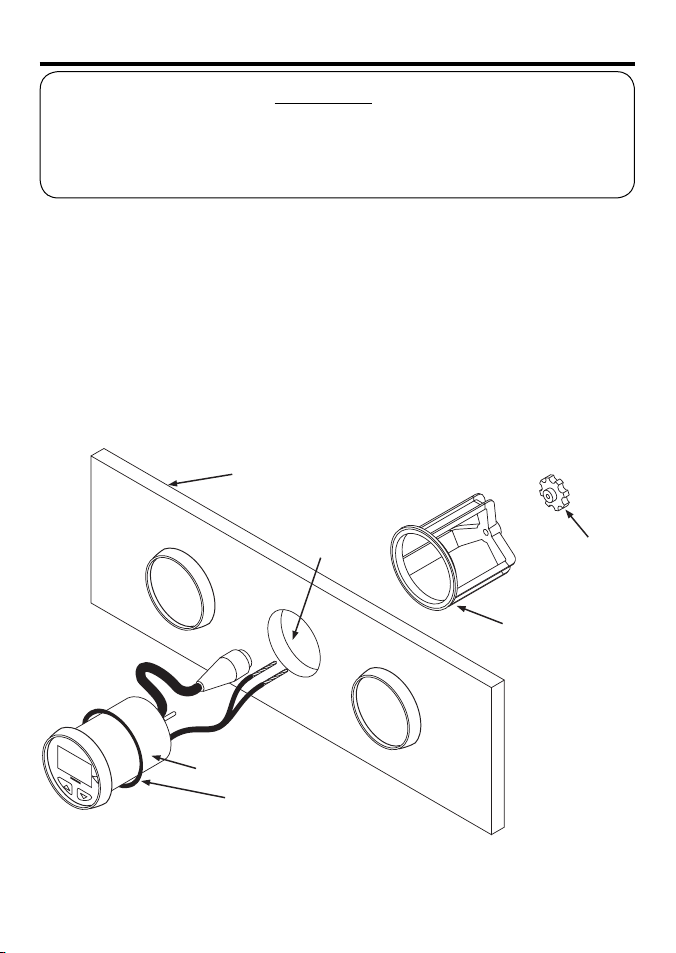
Instrument
Panel
51mm (2”)
Instrument
Sealing
Gasket
Mounting
The instrument panel must be 3mm to 19mm
(1/8” to 3/4”) in thickness.
• Drill a 51mm (2”) hole in the instrument panel.
• Remove brackets and insert the instrument
so the back is flush with the instrument panel.
• Slide the bracket over the instrument and
tighten the mounting nut until secure.
Hole
Mounting Nut
Mounting
Bracket
Northstar Explorer F210 Installation and Operation Manual8
Page 9
Wiring Conne ction
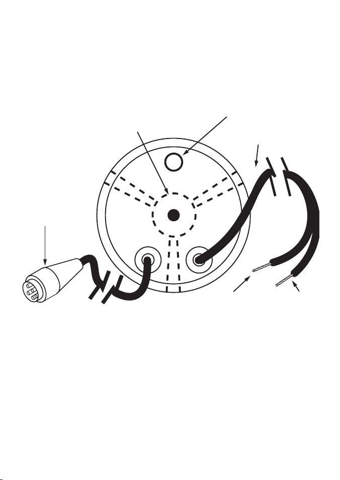
(+)
(-)
• Keep electrical and transducer cables away
from alternator or other noise generating
electrical cables. Avoid connecting the
instrument to power circuits that share
loads with ignition, alternators, inverters and
radio transmitters. Electrical power supply
connections should always be as short as
possible.
BRACKET
FUJI 5-PIN
CONNECTOR
• Connec t the red wire to the positive supply
via a 1 amp fuse or a 1 amp circuit breaker.
Connect the black wire to the electrical
ground.
• Connec t the fuel flow transducer to the five
pin transducer inlet cable.
BUZZER
600mm (24”)
POWER CORD
Installat ion of the fuel flow transdu cer
The fuel f low transducer is designed for
installation in Coast Guard approved 9.5 mm
(3/8”) flexible fuel line. The transducer MUST be
installed AFTER the main fuel filter. It should be
located well away from any area where it will be
effec ted by excessive heat or vibration from the
engine. It is preferable to mount the transducer in
a vertical position.
Northstar Explorer F210 Installation and Operation Manual 9
RED
TERMINAL
Drain all the fuel from the f lexible fuel line. Cut
the fuel line and using the fuel hose fixing clips
provided install the transducer so that the FUEL
IN side of the transducer connects to the fuel
tank.
BLACK
TERMINAL
Page 10
Appendix A - Specifications
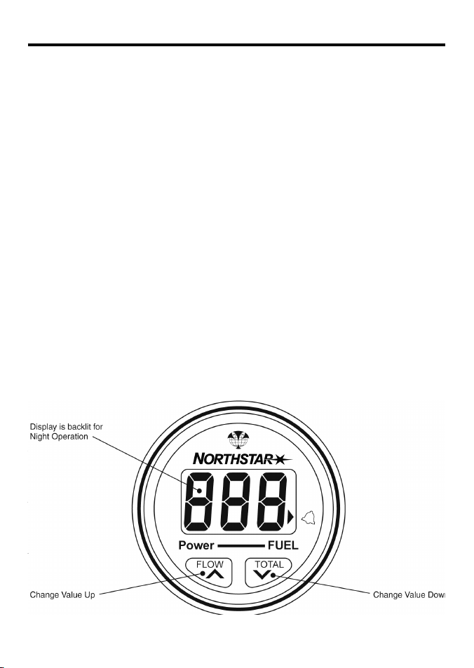
• Size
Mount - 51mm diameter hole
Depth behind face plate - 95mm max.
Display - 3-character LCD
• Colour
Black with texture on bezel.
• Backlighting
Red coloured diffused lighting for display.
• Water Integrity
Front will withstand direct water spray.
• Alarm
Audio and visual alarm indicates remaining
fuel total has dropped below a preset alarm
value.
• Flow
2.5 to 160 litres per hour
0.5 to 43 US gallons per hour
0.4 to 36 imperial gallons per hour
• Logs
Logs record fuel used up to 999 display units.
Total Log is saved in memory at power down.
Both Trip Log and Total Log can be reset via
the keypad.
• Fuel Remaining
User enters a fuel value into memory via
the key pad. The quantity of fuel used is
automatically subtracted from this total. This
value remains in memory at power down.
• Operating Voltage
8 V DC to 16.5 V DC.
• Operating Temperature
0 to 50°C (32 to 122°F).
• Current Drain
70 mA max .
• RF Interference
<6 dB quieting on any marine radio channel
(with 3 dB gain antenna) within one metre
of the instrument. Complies with CE EMC
standards EN50081-1 and EN50082-1.
Northstar Explorer F210 Installation and Operation Manual10
Page 11

Appendix B - Troubleshooting Chart
No display:
1. Check DC power connections and DC
polarity with voltmeter.
2. Check fuse.
No flow reading indicated:
1. Check connection to flow transducer.
2. Remove transducer from fuel line, blow
through transducer, a whistling noise will
indicate the turbine is rotating.
Low flow reading indicated:
1. Check that the gauze filter is clean. If the filter
is not installed fine strands may clog up the
turbine.
2. Check calibration is correct.
High or erratic reading:
Check fuel connections are well made. Air in
fuel lines will cause erratic or high readings.
Northstar Explorer F210 Installation and Operation Manual 11
Page 12

AMERICAS
30 Sudbury Road,
Acton, MA 01720, USA
Ph: +1 978.897.6600
Ph: +1 800.628.4487
Fax: +1 978.897.7241
EUROPE
Unit 2, Ocean Quay,
Belvidere Rd, Southampton,
SO14 5QY, ENGLAND
Ph: +44 2380 339922
Fax: +44 2380 330345
AUSTRALIA
PO Box 479,
Gladesville, NSW 2111,
AUSTRALIA
Ph: +61 2 9879 9060
Fax: +61 2 9879 9009
www.northstarnav.com
NEW ZEALAND
PO Box 68 155,
Newton, Auckland
Auckland, NEW ZEALAND
Ph: +64 9 481 0500
Fax: +64 9 481 0590
Made in New Zealand
MN000207A
 Loading...