

Page 1
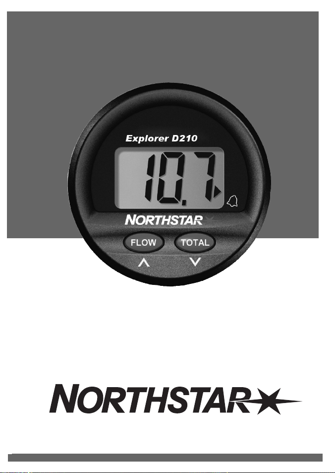
Explorer D210
Installation and Operation Manual
www.northstarnav.com
Page 2
IMPORTANT SAFETY INFORMATION
Please read carefully before installation and use.
This is the safety alert symbol. It is used to alert you to potential
personal injury hazards, Obey all safety messages that follow this symbol to
avoid possible injury or death.
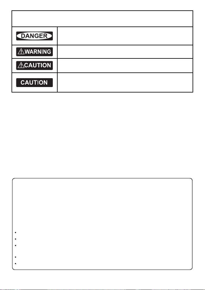
WARNING indicates a potentially hazardous situation which, if not avoided,
could result in death or serious injury
CAUTION indicates a potentially hazardous situation which, if not avoided, could
result in minor or moderate injury.
CAUTION used without the safety alert symbol indicates a potentially
hazardous situation which, if not avoided, may result in property damage.
DISCLAIMER: It is the owner’s sole
responsibility to install and use the instrument
and transducers in a manner that will not cause
accidents, personal injury or property damage.
The user of this product is solely responsible for
observing safe boating practices.
BRUNSWICK NEW TECHNOLOGIES INC. AND ITS
SUBSIDIARIES AND AFFILIATES DISCLAIM ALL
LIABILIT Y FOR ANY USE OF THIS PRODUCT IN A
WAY THAT MAY CAUSE ACCIDENTS, DAMAGE OR
THAT MAY VIOLATE THE LAW.
Governing Language: This statement,
any instruction manuals, user guides and
other information relating to the product
(Documentation) may be translated to, or
has been translated from, another language
(Translation). In the event of any conf lict
between any Translation of the Documentation,
the English language version of the
Documentation will be the official version of the
Documentation.
This manual represents the Explorer D210
as at the time of printing. Brunswick New
Technologies Inc. and its subsidiaries and
affiliates reserve the right to make changes to
specifications without notice.
Copyright © 2006 Brunswick New Technologies
Inc. Northstar™ is a registered trademark of
Brunswick New Technologies Inc
FCC Statement
Note: This equipment has been tested and found to comply with the limits for a Class B digital device,
pursuant to Part 15 of the FCC Rules. These limits are designed to provide reasonable protection against
harmful interference in a normal installation. This equipment generates, uses and can radiate radio
frequency energy and, if not installed and used in accordance with the instructions, may cause harmful
interference to radio communications. However, there is no guarantee that interference will not occur in
a particular installation. If this equipment does cause harmful interference to radio or television reception,
which can be determined by turning the equipment off and on, the user is encouraged to try to correct
the interference by one or more of the following measures:
Re orient or relocate the receiving antenna.
Increase the separation between the equipment and receiver.
Connect the equipment into an output on a circuit different from that to which the receiver is
connected.
Consult the dealer or an experienced technician for help.
A shielded cable must be used when connecting a peripheral to the serial ports.
Northstar Explorer D210 Installation and Operation Manual2
Page 3

Contents
1 Operati on ..............................................................................................................................................4
Alarms . . . . . . . . . . . . . . . . . . . . . . . . . . . . . . . . . . . . . . . . . . . . . . . . . . . . . . . . . . . . . . . . . . . . . . . . . . . . . . . 4
Alarms On/Off . . . . . . . . . . . . . . . . . . . . . . . . . . . . . . . . . . . . . . . . . . . . . . . . . . . . . . . . . . . . . . . . . . . . . . . 4
Shallow Alarm . . . . . . . . . . . . . . . . . . . . . . . . . . . . . . . . . . . . . . . . . . . . . . . . . . . . . . . . . . . . . . . . . . . . . . . . 4
Deep Alarm . . . . . . . . . . . . . . . . . . . . . . . . . . . . . . . . . . . . . . . . . . . . . . . . . . . . . . . . . . . . . . . . . . . . . . . . . . 4
2 Instru ment Setup .................................................................................................................................. 5
Keel/Surface Offset . . . . . . . . . . . . . . . . . . . . . . . . . . . . . . . . . . . . . . . . . . . . . . . . . . . . . . . . . . . . . . . . . 5
Transducer Setting . . . . . . . . . . . . . . . . . . . . . . . . . . . . . . . . . . . . . . . . . . . . . . . . . . . . . . . . . . . . . . . . . . 5
Units of Measure . . . . . . . . . . . . . . . . . . . . . . . . . . . . . . . . . . . . . . . . . . . . . . . . . . . . . . . . . . . . . . . . . . . . 5
3 Dual Stat ion Operation ......................................................................................................................... 6
Master/Slave Selection . . . . . . . . . . . . . . . . . . . . . . . . . . . . . . . . . . . . . . . . . . . . . . . . . . . . . . . . . . . . . . 7
Linked or Separate Selection . . . . . . . . . . . . . . . . . . . . . . . . . . . . . . . . . . . . . . . . . . . . . . . . . . . . . . . . 7
4 Maintena nce ........................................................................................................................................ 8
5 Instal lation .......................................................................................................................................... 8
Instrument Installation . . . . . . . . . . . . . . . . . . . . . . . . . . . . . . . . . . . . . . . . . . . . . . . . . . . . . . . . . . . . . . 8
6 Wiring .................................................................................................................................................. 9
Append ix A - Specifica tions ................................................................................................................... 10
Append ix B - Troubleshooting ................................................................................................................ 11
Append ix C - How to contact us ................................................................................................................ 12
Northstar Explorer D210 Installation and Operation Manual 3
Page 4
1 Operation
OFF
ON
OFFON
OFFON
OFF
ON
OFFON
OFFON
OFFON
OFF
ON
Whenever power is applied the depth sounder is
active and water depth is displayed. If the sonar
signal does not show a bottom the display will
indicate “- -”. This can occur if the water is aerated
or the maximum depth is exceeded.
Note: The maximum depth d ecreases as boat speed
increases.
Alarms
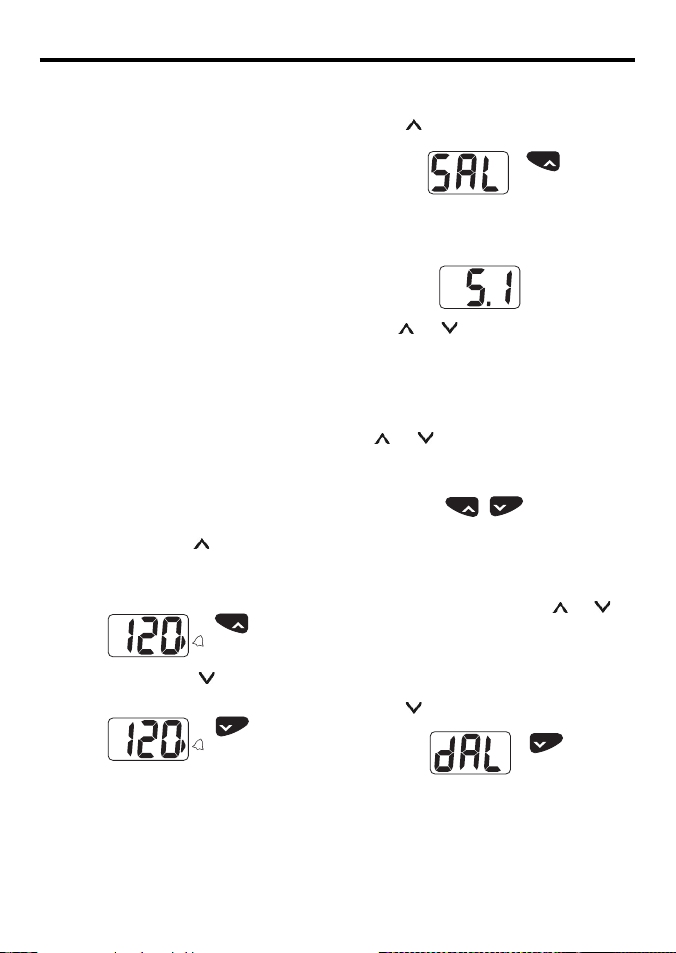
Two types of alarms can be set; the Deep Alarm
and the Shallow Alarm. The Deep Alarm can be
set as high as 184 metres (605 feet) while the
Shallow Alarm can be set as low as 0.3 metre (1
foot).
Whenever the water depth is greater than the
Deep Alarm setting and the alarm is enabled an
alarm will sound. The alarm repeats two short
beeps and alternates DAL and the water depth
on the display.
Whenever the water depth is less than the
Shallow Alarm setting and the alarm is enabled
an alarm will sound. The alarm repeats a single
long beep and alternates SAL and the water
depth on the display.
Alarms On/Off
Alarm settings are saved in memory.
To turn the alarm on, press
the lower right corner of the display will show
(next to the Alarm Bell), to indicate that the
alarms are on.
To turn the alarms of f, press
in the lower right corner will ex tinguish.
Note: The arrow will fl ash if alarms are turned ON
but the shallow alarm is ind ividually set to OFF. See
next section.
(ON). An arrow on
ON
(OFF). The arrow
OFF
Shallow Al arm
To set the shallow alarm:
1. Press
for three seconds. The display will
show:
ON
Press for 3
Seconds
2. After a few seconds the display will indicate
the current Shallow Alarm depth setting.
3. Use
and to change the value. If either
key is held depressed for more than one
second the reading will increase or decrease
rapidly.
4. When the alarm is set, exit by pressing both
and simultaneously. Alternatively, if no
keys are pressed for a period of 5 seconds the
normal depth display will resume.
OFF
ON
Press simultaneously to exit
Note: If the reading is decreased to b elow
1.5 feet (or equivalent) the display will
show OFF and the alarm will be disabl ed. The alarm
can also be disabled by pressing bo th
and for
5 seconds. The word OFF will be displayed b ut the
alarm depth will be retained for f uture use.
Deep Alarm
To set the deep alarm:
1. Press
2. After two seconds the display will indicate
for three seconds. The display will
show:
OFF
Press for 3
Seconds
the current Deep Alarm depth setting.
Northstar Explorer D210 Installation and Operation Manual4
Page 5
3. Use
OFF
ON
OFFON
OFFON
OFFON
OFFON
OFFON
OFF
ON
OFFON
OFF
ON
OFFON
and to change the value. If either
key is held depressed for more than one
second the reading will increase or decrease
rapidly.
4. When the alarm is set, exit by pressing both
and simultaneously. Alternatively, if no
keys are pressed for a period of 5 seconds the
normal depth display will resume.
2 Instrument Setup
Keel/ Surface Of fset
An offset may be automatically added to
or subtracted from the depth reading to
compensate for the location of the transducer.
This allows the instrument to indicate the water
depth relative to the bottom of the keel or the
surface of the water.
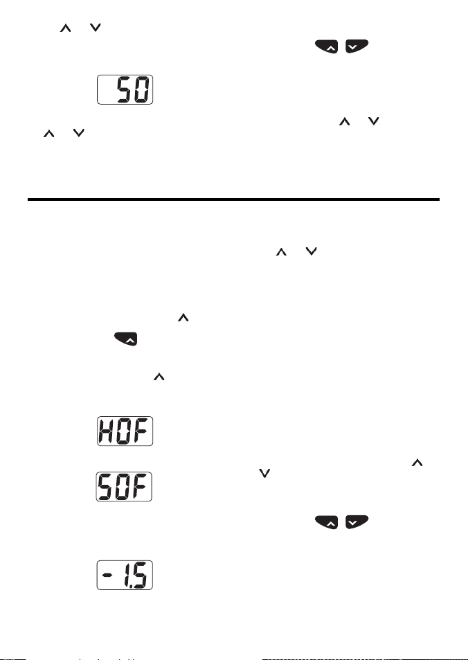
To set the keel/surface offset:
1. Apply power while holding down
ON
Hold down during p ower up
2. When the unit is on, release
will indicate if the current of fset is keel offset
or waterline offset:
Hull Offse t (Depth below the keel)
Surface Off set (Depth below the surface)
3. After 5 seconds the display will indicate the
current offset.
. The display
Northstar Explorer D210 Installation and Operation Manual 5
OFF
ON
Press simultaneously to exit
Note: If the reading is increased one ste p above 600
feet (or equivalent) the d isplay will show OFF and
the alarm will be disabled . The alarm can also be
disabled by pressing both
and for 5 seconds.
The word OFF will be displayed but the alarm depth
will be retained for future use.
Note: A negative off set is used to display depth
below the keel and a p ositive offset is used to display
depth below the sur face.
4. Use
and to change the value. If either
key is held depressed for more than one
second the reading will increase or decrease
rapidly.
5. The offset can be programmed in 0.1 unit
.
steps from -9.9 to 9.9 feet (or equivalent).
When programmed for a negative offset, ‘-’
will be indicated on the lef t hand side of the
display.
6. To display depth below the keel enter the
vertical distance bet ween the bottom of the
keel and the depth transducer as a negative
value.
7. To display depth below surface enter the
vertical distance from the waterline to the
depth transducer as a positive number (no
negative sign).
8. To exit this mode, press and hold both
and
simultaneously. Alternatively, if no keys
are pressed for a period of 5 seconds normal
depth display will resume.
OFF
ON
Press simultaneo usly
The display will now indicate the current water
depth.
Page 6
Tran sduce r Set ting
OFFON
OFFON
OFFON
OFFON
OFFON
OFF
ON
OFFON
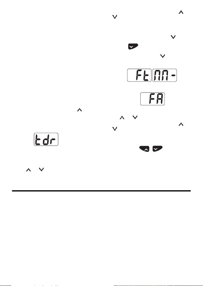
A Transducer Setting is provided to allow
the Explorer D210 to be used with different
transducer t ypes. The default setting (= 0.0) is
used for most transducers.
Some transducers ‘ring’ af ter the sonar transmit
pulse (just like hitting a bell). This ringing can be
interpreted as an echo from a shallow bottom.
The setting is used to increase the required level
that shallow echoes must meet before they will
be displayed.
If the Explorer D210 gives repeated false readings
of 1.5 to 3 feet depth while in deep water the
transducer set ting should be increased. Adjust it
upward by 0.5 at a time and re test. The range of
values is -0.9 to +2.5. If the value is set too high it
could cause erratic readings in shallow water.
Changing the Transducer Setting:
1. Apply power while holding down
display will show either HOF or SOF for 7
seconds. Continue to hold the key down.
2. The display will show tdr.
3. Release the key.
4. After 2 seconds the display will show the
Transducer Setting value eg 0.0.
5. Use
and to change the value.
. The
6. To exit this mode, press and hold both
simultaneously.
Units of Me asure
To select the displayed unit
1. Apply power while holding down
OFF
Hold down during
power up
2. When the unit is on, release
will indicate the current display unit with:
Feet Metres
Fathoms
3. Use
and to change the value.
4. To exit this mode, press and hold both
simultaneously. Alternatively, if no keys
are pressed for a period of 5 seconds normal
depth display will resume.
OFF
ON
Press simultaneo usly
The display will now indicate the current water
depth in the selected display unit.
.
. The display
and
and
3 Dual Station Operation
Multiple Explorer 210 instruments can be
installed on a single vessel. These instruments
can be connected together and configured to
operate in a dual station configuration. One
instrument is designated as a master and all other
instruments, connected to it, are configured as
slaves. The master device is connected to the
depth transducer and determines the water
depth. This information is then displayed on all
slave devices connected to it. Slave devices do
not have transducers connec ted to them.
The slave devices can be configured to operate
as fully functional NMEA repeaters where
they display water depth, as displayed on
Northstar Explorer D210 Installation and Operation Manual6
the master device, and share common alarm
settings and keel offset values. In this mode
the common alarm settings can be changed or
activated/deactivated from either the master or
slave devices.
Alternatively, the slaves can be configured to
operate as independent slaves. In this mode the
slaves display the water depth received from the
master, but have independent alarm settings and
keel offset values.
Note: The instrument design ated as the
master device is the only instrum ent connected to
the depth transducer.
Page 7
Master/Slave Selection
OFFON
OFFON
OFFON
OFF
ON
OFFON
OFFON
OFFON
OFF
ON
OFFON
OFFON
OFFON
OFFON
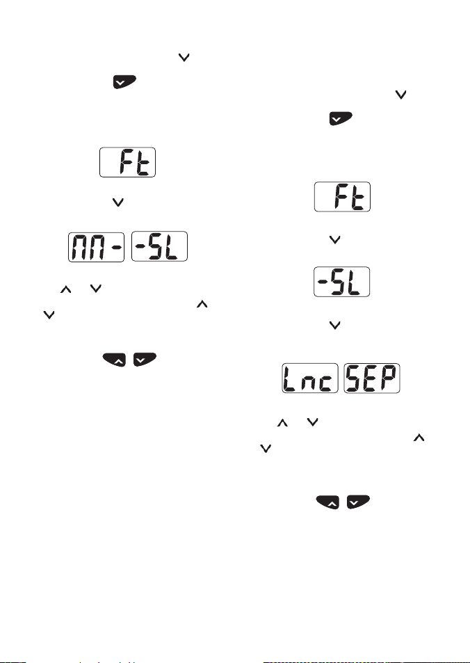
To select the master/slave mode of operation:
1. Apply power while holding down
OFF
Hold down during p ower up
2. When the unit is on. The display will indicate
the current display unit:
example
3. Continue to hold
until the display
indicates the current master/slave selection.
Master Slave
4. Use
and to change the selection.
5. To exit this mode, press and hold both
simultaneously. Alternatively, if no keys
are pressed for a period of 5 seconds normal
depth display will resume.
OFF
ON
Press simultaneo usly
Note: If the data link is inadvertently bro ken then
the display will alternate bet ween -- and -SL.
Linked or Separate Selection
By default a dual station pair of Explorer D210
instruments automatically keep the following
settings the same in both instruments:
Alarms On/Off
Alarm Values (Deep and Shallow)
Keel Offset (see note)
Units of measure (see note)
Example: Switching an alarm off on the slave
instrument will also switch the alarm off
on the master instrument. The reverse also
applies, alarms changed on the master will be
automatically changed in the slave instrument.
Northstar Explorer D210 Installation and Operation Manual 7
Note: The keel off set and units of measure should
only be changed on the M aster instrument.
.
If independent settings are required the link
feature can be disabled.
To enable or disable the linked mode:
1. Apply power while holding down
OFF
.
Hold down during power up
2. When the unit is on. The display will first
indicate the current display unit:
Example
3. Continue to hold
. The display will indicate
the current master/slave selection.
and
4. Continue to hold
Slave
until the display
indicates the current linked /separate
selection.
Linked Separate
5. Use
6. To exit this mode, press and hold both
and to change the selection.
and
simultaneously. Alternatively, if no keys
are pressed for a period of 5 seconds normal
depth display will commence.
OFF
ON
Press simultaneo usly
Note: This setup procedure appl ies to the master
device and all slave de vices. For separate operation
all devices, includin g the master, must be set to
Separate mode. Also, for linked op eration all devices,
including the master, must be set to Linked mode .
Page 8
4 Maintenance
Your depth sounder is designed for years of trouble free operation assuming proper installation and care
are provided. Following the operation and installation guidelines in this manual should ensure optimum
performance of the instrument. In the unlikely event that the instrument shall fail to perform or shall
need ser vicing, contact the dealer whom you purchased your Explorer D210 from.
5 Installation
Instrument Installation
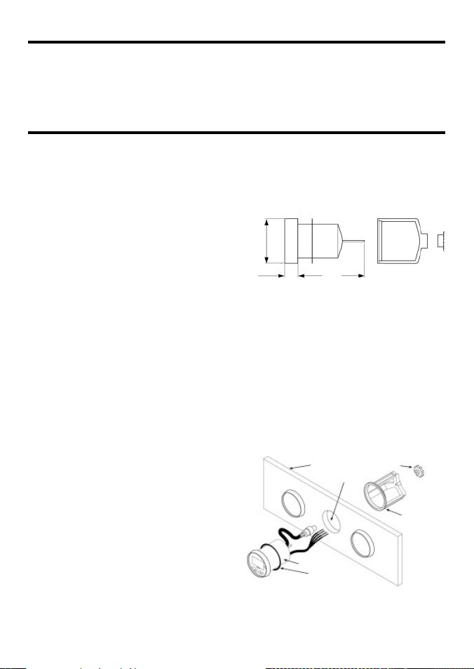
The instrument can be easily installed in different
types of instrument panels.
1. Select a suitable location for the instrument.
When selecting the location for mounting,
the following are recommended:
• Controls of the instrument must be
accessible to the user.
• Electrical connections must be routed to
the boat system as directly as possible,
minimising the length of cable where
practical.
• Location should provide as much
protection from the elements as possible.
• The panel for mounting the instrument
should be 3 mm to 19 mm (1/8 to 3/4
inch) thick.
• The space behind the instrument panel
must have a depth of at least 95 mm (3.75
inches).
2. Drill a 51 mm (2-inch hole) on the instrument
panel in the selected location.
3. With the mounting bracket removed, insert
the instrument into the hole until the back
of the face plate is flush with the outside
mounting wall.
4. Slide the bracket over the body of the
instrument. Note: Orient the bracket in such a
manner that it does not cover the buzzer.
5. Tighten the mounting nut until the bracket is
secure.
6. Connect the power cord at the back of the
instrument to a 12 V power supply which is
active whenever the ignition switch is on.
The red lead should be connected to the
positive terminal of the power supply via a 1
amp fuse or a 1 amp circuit breaker. The black
lead should be connected to the negative
terminal.
2.5”
6.35 mm
.75”
19 mm
3.75”
95 mm
7. Obtain the power from a 12 V source as
directly as possible. Avoid power circuit s
which share loads with ignition, alternators,
radio transmitters, etc. Excessive electrical
noise associated with such devices may
prevent the instrument from operating
properly.
8. Connect the RCA phono plug on the
transducer cable to the instrument. Ex tension
cables are available from your Northstar
dealer if the transducer cable is too short.
Instrument
panel
51 mm (2”) Hole
Instrument
Sealing gasket
Mounting Nut
Mounting
Bracket
Northstar Explorer D210 Installation and Operation Manual8
Page 9
6 Wiring
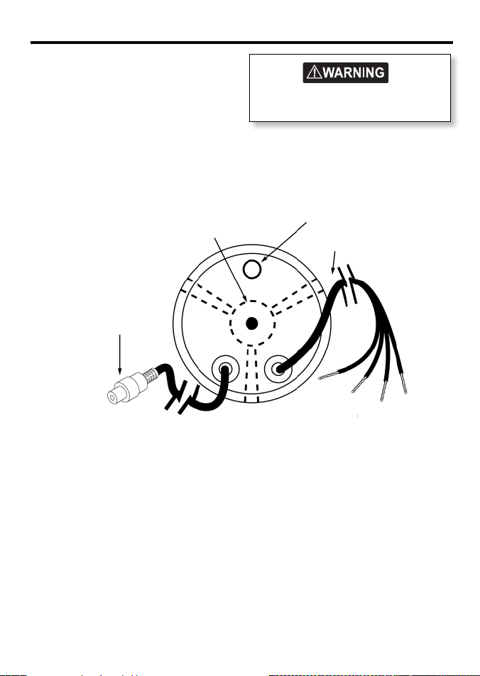
• Red (+) Terminal
• Black (-) Terminal
• Orange Ex ternal Buzzer
Use for optional external buzzer (use red (+)
terminal to complete circuit). If unused then
tape to avoid shorting.
• Brown Data in put/output
Your Explorer D210 can be used as a repeater
for another DPT or DBT NEMA depth sounder.
If unused then tape to avoid shorting.
Bracket
RCA Jack Connector
If unsure about wiring contact your
nearest Northstar dealer.
Buzzer
600 mm (24 inch)
Power Cord
Red (+)
Black (-)
Orange
Brown
Northstar Explorer D210 Installation and Operation Manual 9
Page 10
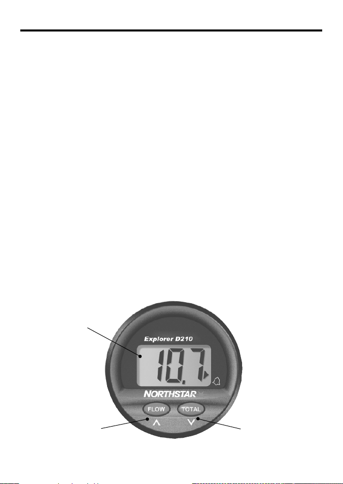
Appendix A - Specifications
• Size
Mount: 51 mm (2”) diameter hole
Depth behind face plate: 95 mm (3.75”) max.
Display: 3-charac ter LCD
• Color
Black bezel.
• Backlighting
Red colored diffused lighting for display.
• Water Integrity
Front will withstand direct water spray.
• Depth/Alarm Range
2.0-600 feet
0.6-184 metres
0.3-100 fathoms
(to 9.9 in tenths)
• Sensitivity
Better than 0.05 mV RMS at 200 feet.
• Transmit Power
36 W RMS nominal at 13.6 V DC.
• Transducer
200 kHz 1900 pF/600 W parallel.
• Display Updating
1 second.
Display is backlit for
Night operation
• Operating Voltage
9.5 V DC to 16.5 V DC.
• Operating Temperature
0°C to 50°C (32° F to 122°F).
• Current Drain
150 mA max, including internal buz zer.
• Data Input/Output
Single wire data output/Input.
Dual station mode outputs NMEA sentences.
Dual station accepts NMEA sentences. In the
linked mode a dual station pair also transfer
function settings eg. Alarm on/off.
• NMEA Output
DPT.
• NMEA Input
DPT and DBT.
• External Buzzer Output
12 V DC Buzzer, 100 mA max.
• RF Interference
<6 dB quieting on any marine radio channel
(with 3 dB gain antenna) within one meter
of the instrument. Complies with CE EMC
standards EN50081-1 and EN50082-1.
Alarm On/
Change Value up
Alarm Off/
Change Value
Down
Northstar Explorer D210 Installation and Operation Manual10
Page 11

Appendix B - Troubleshooting
No display:
1. Check DC power connections and DC
polarity with voltmeter.
2. Check fuse.
No depth rea ding (--) at all depths:
1. Check transducer for growth or multiple
coats of paint.
2. Check the transducer cable for cuts and
sharp bends.
3. Check that the transducer connection
behind the E xplorer D210 is firm and free
of corrosion.
Erratic readi ngs while moored:
1. Check transducer for growth or multiple
coats of paint.
Erratic readi ngs while moving:
1. Cavitation (air) under the face of the
transducer. Review installation and
reinstall if necessary.
Erratic readi ngs only while engine is run ning:
1. Re-route power and transducer cables
away from engine, ignition wires and
battery cables.
2. Add feed-through filter capacitor on the
positive terminal of the ignition coil.
3. Add an alternator whine filter to
alternator.
4. Replace spark plug wire with resistive
type.
Northstar Explorer D210 Installation and Operation Manual 11
Page 12

AMERICAS
30 Sudbury Road,
Acton, MA 01720, USA
Ph: +1 978.897.6600
Ph: +1 800.628.4487
Fax: +1 978.897.7241
EUROPE
Unit 2, Ocean Quay,
Belvidere Rd, Southampton,
SO14 5QY, ENGLAND
Ph: +44 2380 339922
Fax: +44 2380 330345
AUSTRALIA
PO Box 479,
Gladesville, NSW 2111,
AUSTRALIA
Ph: +61 2 9879 9060
Fax: +61 2 9879 9009
www.northstarnav.com
NEW ZEALAND
PO Box 68 155,
Newton, Auckland
Auckland, NEW ZEALAND
Ph: +64 9 481 0500
Fax: +64 9 481 0590
Made in New Zealand
MN000597A-G
 Loading...