

NorthStar Navigation 978-897-6600, 800-628-4487 User Manual
958
INTEGRATED NAVIGATION SYSTEM
I
NSTALLATION
Part Number GM958IM Revision A1
M
ANUAL
Northstar Technologies
30 Sudbury Road
Acton, Massachusetts 01720
800/628-4487
978/897-6600
www.northstarcmc.com

Limited warranty policy
Northstar Technologies, Inc. warrants the Northstar 958 to be free from defects in materials and
workmanship for a period of two (2) years. This warranty applies to the original purchaser and to any
subsequent owner during the warranty period, which begins on the date of shipment of the unit,
F.O.B. Acton, Massachusetts, to an authorized Northstar dealer.
Systems may not be returned to Northstar without a Returned Materials Authorization (RMA) number. Call the Northstar dealer or Northstar for instructions.
During the unit’s warranty period, Northstar will repair or replace, at its option, any part of the unit it
finds to be defective due to faulty material(s) or workmanship. All such repairs and/or replacements
will be promptly performed by Northstar free-of-charge to the owner, excluding freight costs
incurred in shipping to the factory. Return shipments from Northstar to points within the United
States are made via ground transportation, freight prepaid. Special shipping charges (overnight,
two-day, and so on) are the responsibility of the owner.
To be covered by this warranty, the Northstar equipment must have been in normal use. This warranty does not apply to units with defects caused by improper installation, physical damage, abuse,
tampering, lightning or other abnormal electrical discharge, or to units with defaced or altered serial
numbers, or to units repaired by unauthorized persons or repaired in a manner that violates Northstar’s recommended service procedures.
All repairs and/or replacements made under this warranty must be performed at Northstar’s facilities
in Acton, Massachusetts. Performance of warranty work elsewhere will not be authorized, and Northstar will not pay for any charges for such work. Northstar will not be responsible for payment of any
charges imposed by a Northstar dealer or other party for services requested by and/or performed for
a unit’s owner in connection with this warranty. Such services might include removal of the unit
from a vessel, inspection, packaging, handling, reinstallation, and the like.
Northstar Technologies assumes no responsibility for any consequential losses of any nature with
respect to any of its products or services sold, rendered, or delivered. The foregoing is the only warranty expressed or implied. No other warranty exists.

Contents
SECTION ONE: Introducing the 958 . . . . . . . . . . . . . . . . . . . . . . . . . . . . . . . . . . . . . . . . . 1
Checking the 958 package . . . . . . . . . . . . . . . . . . . . . . . . . . . . . . . . . . . . . . . . . . . . . . . . . . . . . . . . . 1
SECTION TWO: Installing and wiring the 958 . . . . . . . . . . . . . . . . . . . . . . . . . . . . . . . 3
Bench-testing the 958 . . . . . . . . . . . . . . . . . . . . . . . . . . . . . . . . . . . . . . . . . . . . . . . . . . . . . . . . . . . . . 3
Mounting the 958 . . . . . . . . . . . . . . . . . . . . . . . . . . . . . . . . . . . . . . . . . . . . . . . . . . . . . . . . . . . . . . . . .3
Wiring the 958 . . . . . . . . . . . . . . . . . . . . . . . . . . . . . . . . . . . . . . . . . . . . . . . . . . . . . . . . . . . . . . . . . . . . 6
SECTION THREE: Installing and wiring the 2201 or 2301 . . . . . . . . . . . . . . . . . . . 11
Checking the 2201 and 2301 parts . . . . . . . . . . . . . . . . . . . . . . . . . . . . . . . . . . . . . . . . . . . . . . . . . 11
Mounting and wiring . . . . . . . . . . . . . . . . . . . . . . . . . . . . . . . . . . . . . . . . . . . . . . . . . . . . . . . . . . . . . 12
SECTION FOUR: Installing and wiring the 2701 . . . . . . . . . . . . . . . . . . . . . . . . . . . . 17
Mounting and wiring the 2701 . . . . . . . . . . . . . . . . . . . . . . . . . . . . . . . . . . . . . . . . . . . . . . . . . . . . . 17
Installing the AN205-P antenna . . . . . . . . . . . . . . . . . . . . . . . . . . . . . . . . . . . . . . . . . . . . . . . . . . . . 19
SECTION FIVE: Checking out the system . . . . . . . . . . . . . . . . . . . . . . . . . . . . . . . . . . . 21
Turning the 958 on and off . . . . . . . . . . . . . . . . . . . . . . . . . . . . . . . . . . . . . . . . . . . . . . . . . . . . . . . . 21
Installation-test checklist . . . . . . . . . . . . . . . . . . . . . . . . . . . . . . . . . . . . . . . . . . . . . . . . . . . . . . . . . . 22
SECTION SIX: Interfacing the 958 system . . . . . . . . . . . . . . . . . . . . . . . . . . . . . . . . . . 23
Wiring the connector pins . . . . . . . . . . . . . . . . . . . . . . . . . . . . . . . . . . . . . . . . . . . . . . . . . . . . . . . . . 23
Configuring the NMEA output ports . . . . . . . . . . . . . . . . . . . . . . . . . . . . . . . . . . . . . . . . . . . . . . . .24
Using 200 ppnm output . . . . . . . . . . . . . . . . . . . . . . . . . . . . . . . . . . . . . . . . . . . . . . . . . . . . . . . . . . . 29
Configuring the RS-232 port . . . . . . . . . . . . . . . . . . . . . . . . . . . . . . . . . . . . . . . . . . . . . . . . . . . . . . . 29
Connecting the 958 to a remote display . . . . . . . . . . . . . . . . . . . . . . . . . . . . . . . . . . . . . . . . . . . . .30
Connecting the 958 to a video camera . . . . . . . . . . . . . . . . . . . . . . . . . . . . . . . . . . . . . . . . . . . . . .30
Connecting two Northstar units . . . . . . . . . . . . . . . . . . . . . . . . . . . . . . . . . . . . . . . . . . . . . . . . . . . . 31
Setting the anchor-watch alarm honk . . . . . . . . . . . . . . . . . . . . . . . . . . . . . . . . . . . . . . . . . . . . . . .34
SECTION SEVEN: Troubleshooting and servicing the 958 system. . . . . . . . . . . 35
Troubleshooting installation problems . . . . . . . . . . . . . . . . . . . . . . . . . . . . . . . . . . . . . . . . . . . . . .35
Getting technical support . . . . . . . . . . . . . . . . . . . . . . . . . . . . . . . . . . . . . . . . . . . . . . . . . . . . . . . . . 39
APPENDIX A: 958 system technical specifications. . . . . . . . . . . . . . . . . . . . . . . . . . 43


SECTION ONE: Introducing the 958
Checking the 958 package
The Northstar 958 is a full-featured color GPS navigation system that you can connect to a wide
variety of optional equipment, including the Northstar 490 echo sounder; Northstar radar; and VGA
output equipment, such as the Northstar 1201 remote display. Other optional interfaces include any
NTSC-compatible video input equipment, such as a video camera, TV, DVD, or VHS, and the optional
Northstar 2701 DGPS/WAAS receiver (instead of the 2201 or 2301) for WAAS/GPS/radiobeacon
differential. For installation instructions for the Northstar 490 or Northstar radars, see the Northstar
490 Installation Manual (P/ N G M491) or the Northstar Radar Installation Manual (P/N G MK R adI M).
Table 1: 958 parts list
Part name Part number Qty
958 unit 1
flush-mount hardware kit 957PK 1
flush-mount gasket HG366 1
10-foot interface cable WA215 1
10-foot power cable with 10-amp fuse WA535-D 1
sunshield XP600 1
warranty registration card GD671 1
Northstar 958 Installation Manual GM958IM 1
Northstar 958 Flush-Mounting Template GT958 1
Northstar 958 Operator’s Manual GM958UM 1
WAAS/GPS antenna 2201 or 2301 1
50-foot data/power cable 958POD-CA 1
10-32 UNF mounting screws (2201-on ly ) HS520 3
washers (2201-only) for deck mounting HW500 3
cable heat shrink HM1005 1
958 Installation Manual, Rev. A1 Page 1

SECTION ONE: Introducing the 958
Table 1: 958 parts list
Part name Part number Qty
cable heat shrink HM509 1
6-pin cable connector for AUX port KS672 1
beacon receiver, including:
GPS/DGPS antenna
50-foot AN205-P antenna cable
10-foot pre-finished data/power cable
958 yoke-mount kit 601 YOKE-IK (optiona l) 1
remote control and batteries 958RC (optional) 1
2701 (optional)
AN205-P
WC-256
958BDM-CA
1
1
1
1
Page 2 958 Installation Manual, Rev. A1
SECTION TWO: Installing and wiring the 958
WARNING!
Before starting the installation, be sure to turn power off. Further,
Northstar highly recommends keeping power off while you’re installing
the system. If power is left on or turned on during the installation, fire,
electrical shock, or other serious injury may occur. Be sure that the
voltage of the power supply is compatible with the 958’s voltage rating
of 10 to 36 volts DC. Connecting to the wrong power supply can cause
fire or damage to the equipment. Be sure to ground the equipment to
prevent electrical shock and mutual interference. Be sure to use the
proper fuse. Using the wrong fuse can cause fire or damage to the 958.
Bench-testing the 958
Northstar recommends bench-testing the 958 before installing it onto the vessel. Bench testing
ensures that the equipment is fully operational, and lets the 2201/2301 antenna or 2701 beacon
receiver collect the current almanac and ephemeris data for the installed location, which results in
less on-board installation time.
Mounting the 958
CAUTION!
Proper installation of the Northstar 958 is critical to accurately receive
and effectively use GPS/WAAS signals under a wide variety of weather
conditions.
Keep the following safe compass distance from the 958: 1.0m
standard, 0.8m steerin g.
Choosing the best 958 location
Choose the mounting location carefully—before you drill or cut. The display screen is high-contrast
and anti-reflective, and is viewable in direct sunlight, but for best results, install the 958 out of direct
sunlight. See the figure below for additional mounting recommendations.
958 Installation Manual, Rev. A1 Page 3
SECTION TWO: Installing and wiring the 958
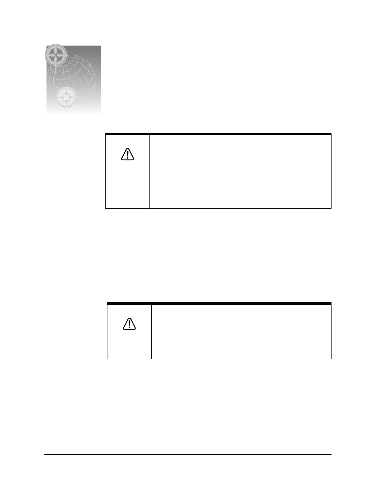
Regardless of the type of mounting, the 958 should be installed in an accessible location
(dry) where the operator can easily use the controls and clearly see the display
screen. Be sure to leave a direct path for all of the cables.
Regardless of the type of mounting, the location should have minimal
glare from windows or bright objects. If the 958 is
yoke-mounted low, tilt the
958 back for best
viewing contrast.
Figure 1: Mounting recommendations
Page 4 958 Installation Manual, Rev. A1
SECTION TWO: Installing and wiring the 958
Flush-mounting the 958
When flush mounting, leave at least two and a half inches of clearance space behind the
mounting panel for all of the cables and connectors. Flush mounting requires good ventilation
behind the mounting panel. Poor ventilation will cause the 958 to overheat, which, in turn, may
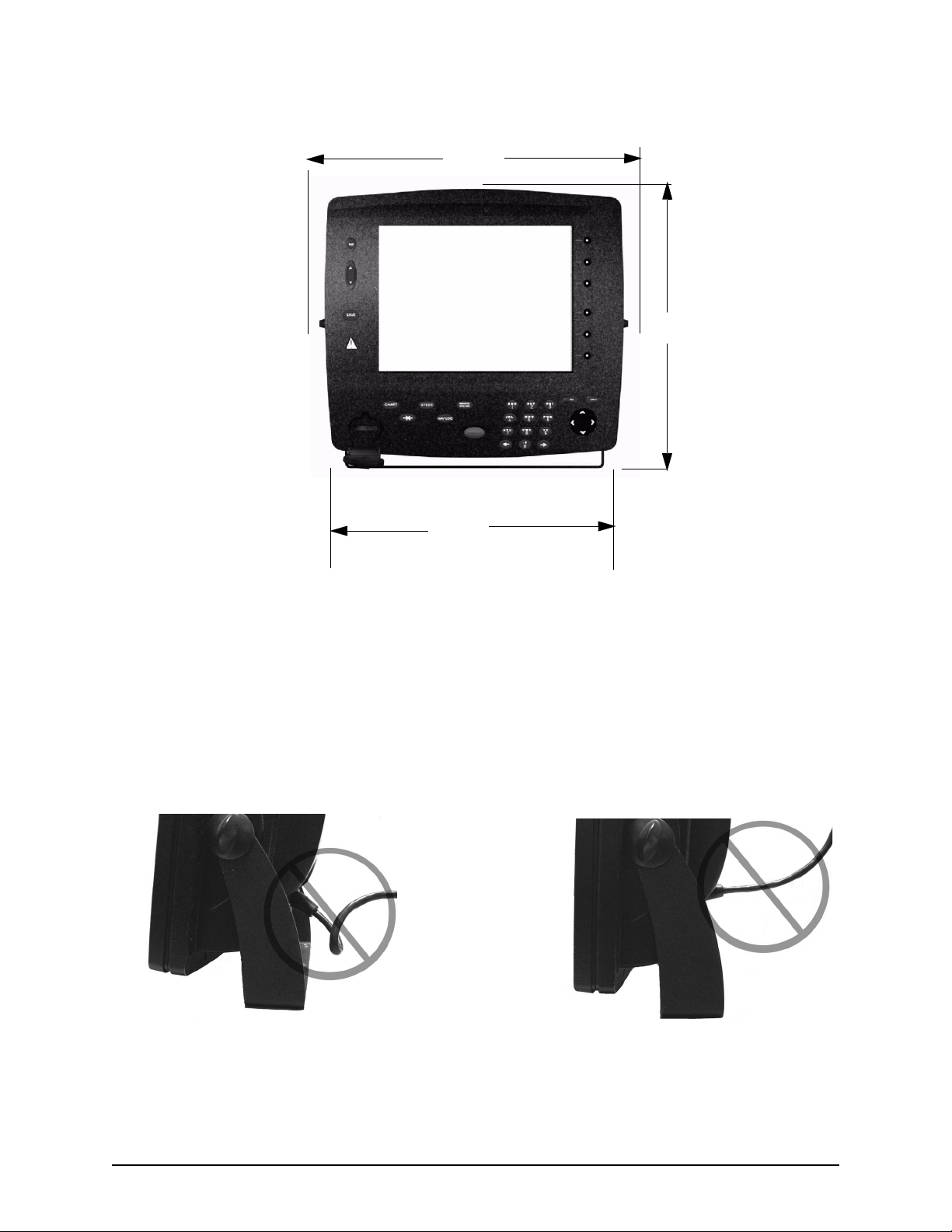
cause the display screen to darken. For overall width and height requirements, see the Northstar 958
Flush-Mounting Template (P/N GT958), which you can use to drill the mounting holes and cut the
mounting panel in the exact recommended locations.
CAUTION!
When flush mounting, be sure to mount the 958 on a flat surface.
Mounting on a curved surface can break or distort the plastic and
break the waterproof seal. Do not overtighten the mounting screws;
you may damage the ca se and compromise its waterpr oof sea l. This
type of physical damage will void the warranty.
Yoke-mounting the 958
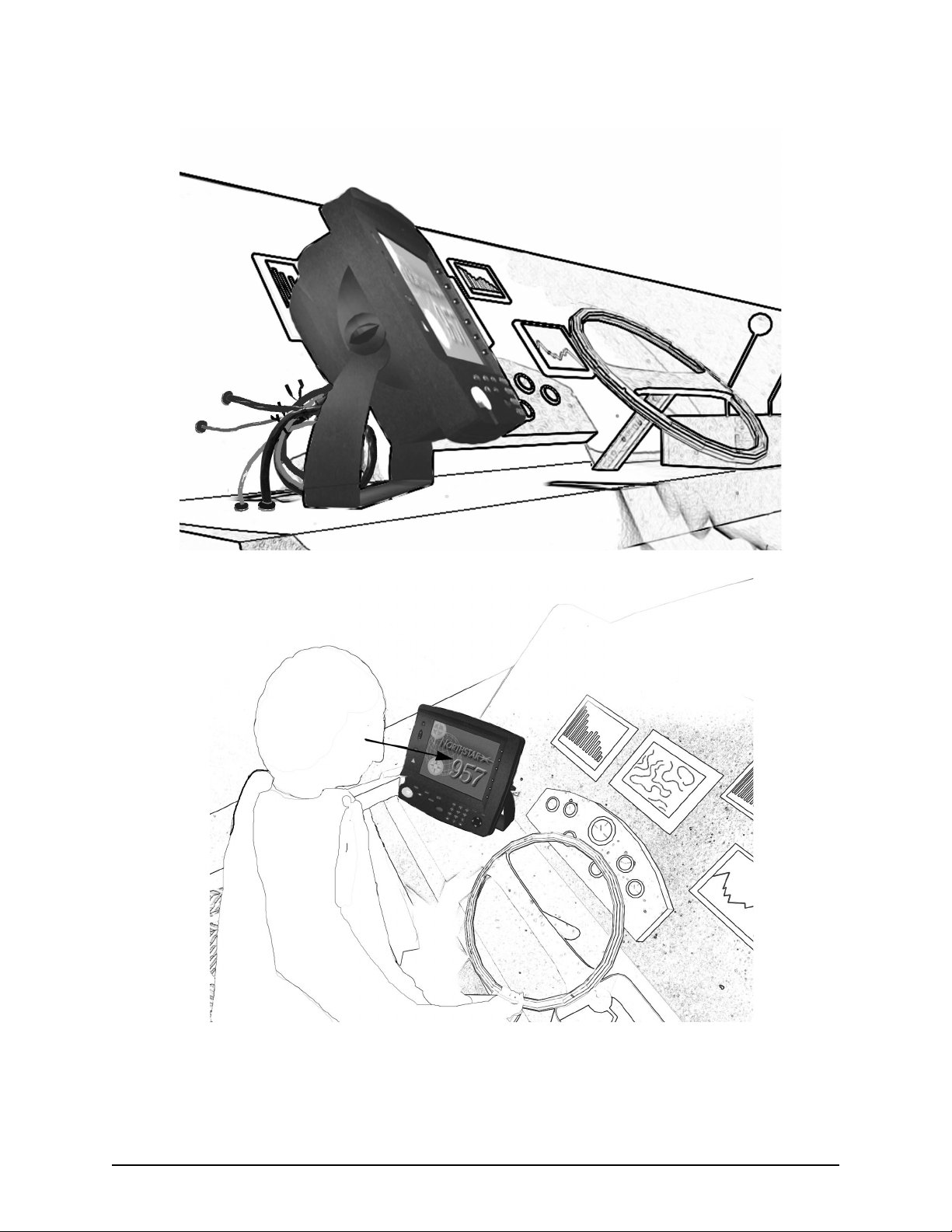
For the recommended mounting clearances, see Figure 2 and Figure 3 below.
6.1”
1.9”
2.3”
2.5
8.2”
12.4”
Figure 2: 958 yoke-mount dimensions (side)
958 Installation Manual, Rev. A1 Page 5
SECTION TWO: Installing and wiring the 958
13.5”
12.4”
11.6”
Figure 3: 958 yoke-mount dimensions (front)
Wiring the 958
Avoiding cable wiring shortcuts
Most installation problems are caused by shortcuts taken with system cables. When wiring the 958,
follow the guidelines in Figure 4 and Figure 5 below.
DON’T DO THIS!
Don’t make sharp bends in the cables
Page 6 958 Installation Manual, Rev. A1
Don’t run cables in
a way that allows water to flow down
Figure 4: Incorrect cable wiring
SECTION TWO: Installing and wiring the 958
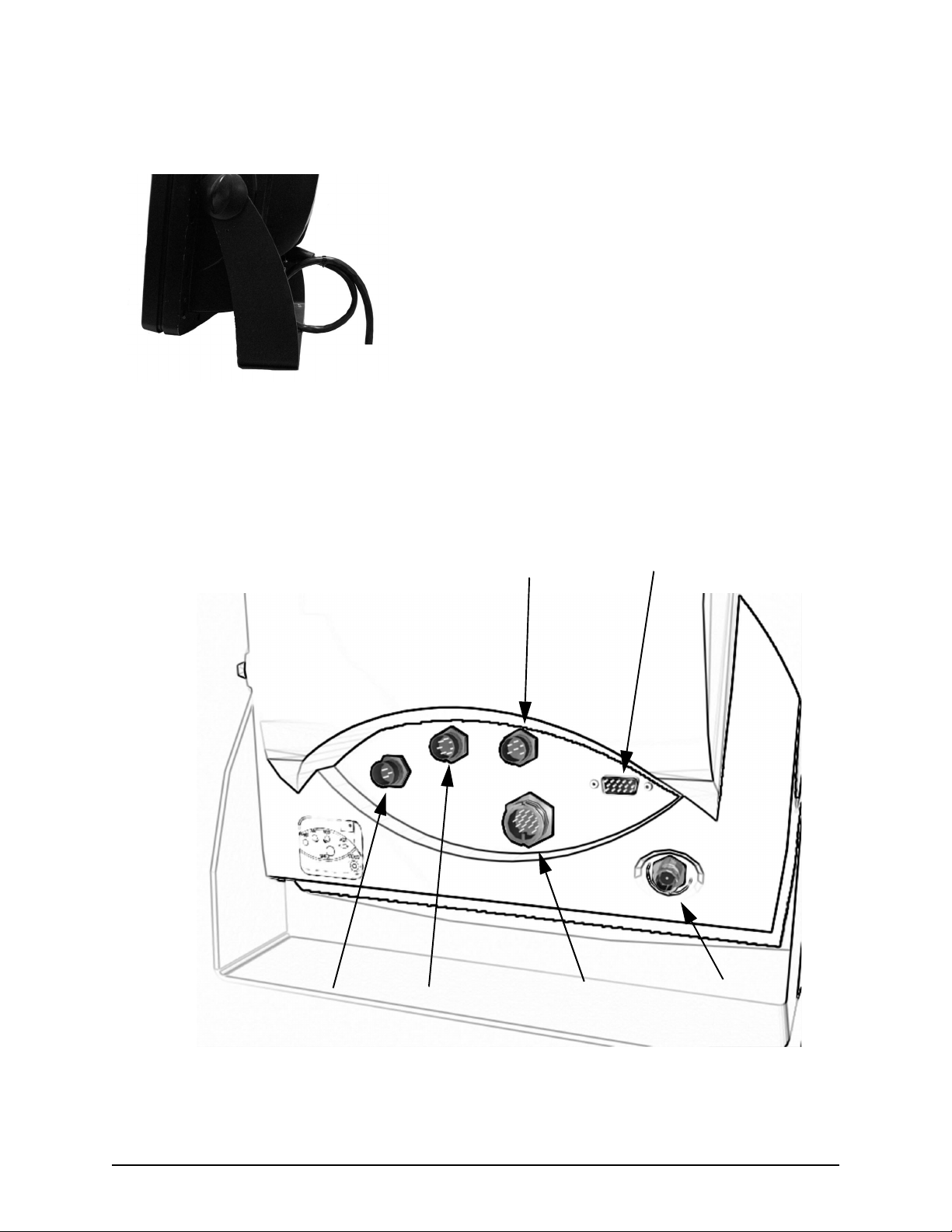
.
DO THIS!
•
Do make drip and serv ic e lo ops
•
Do tie-wrap all cab l es t o ke ep them
secure
•
If cables are shortened,
lengthened, or re-terminated, do
seal and protect all wiring
connections
•
Do leave room at the back to
service the 958
Figure 5: Correct cable wiring
Understanding the interface connectors
All of the 958’s interface connectors are shown in Figure 6: ”Interface connectors (back of 958),”
below. The function of these connectors is described in Table 2, below.
AUX connector
VGA connector
Power connector
GPS connector
NMEA connector VIDEO connector
Figure 6: Interface connectors (back of 958)
958 Installation Manual, Rev. A1 Page 7
SECTION TWO: Installing and wiring the 958
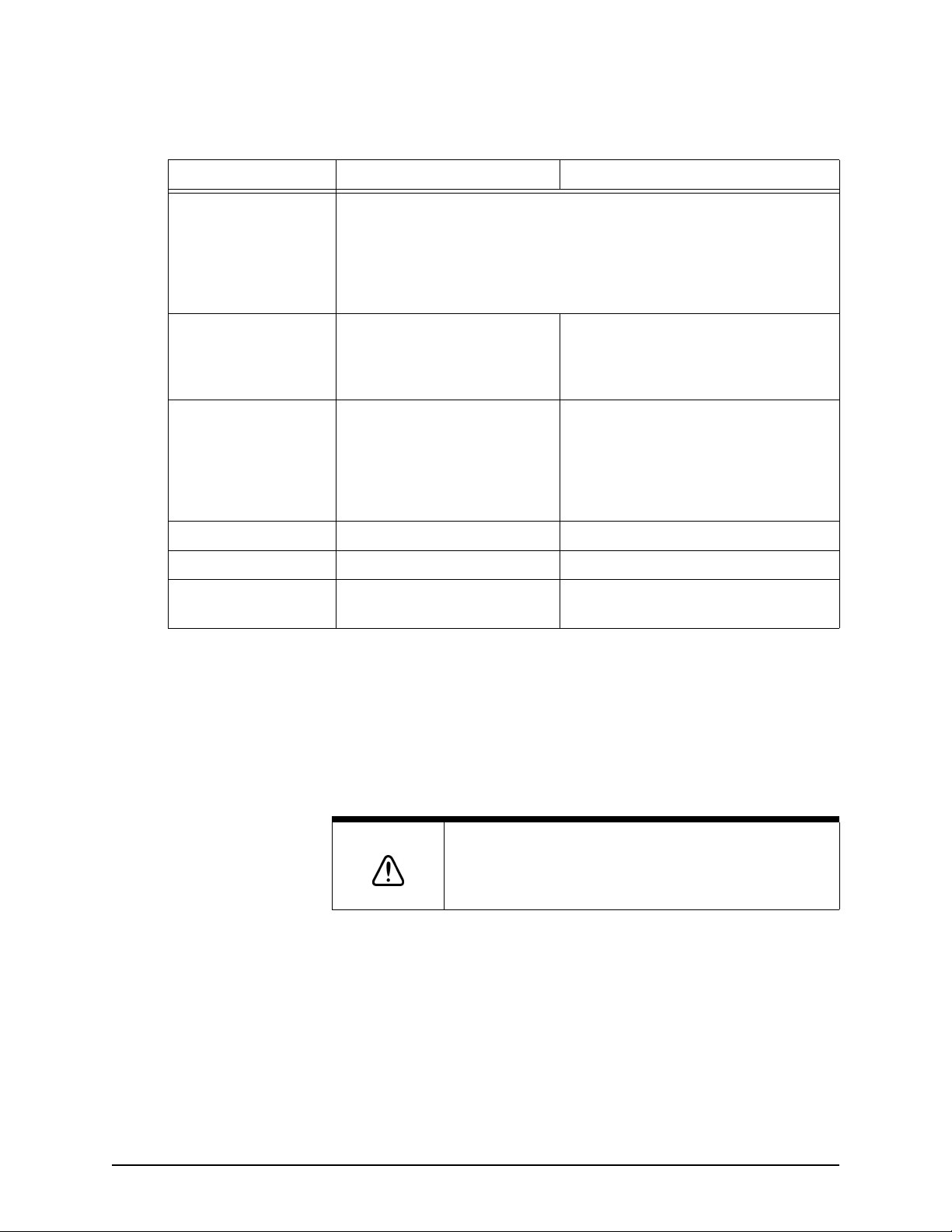
TABLE 2: Interface connector functions
Connector name Connector function(s) Connects to...
NMEA (NMEA I/O)
(18-pin port)
GPS (Antenna)
(7-pin RS232 port)
AUX (Auxiliary)
(6-pin auxiliary NMEA
port)
PWR (Power) Power 10 to 36 VDC, 50 watts
VGA (15-pin port) Video output Remote display
VIDEO (coaxial) Video input Any NTSC-compatible device
NMEA 1 input/output -------------->
NMEA 2 input/output -------------->
Honk alarm/200 ppnm ------------>
GPS/WAAS input/output --------->
Beacon input/output -------------->
RS-422/NMEA input/output -----> Northstar 490 echo sounder (optional)
NMEA devices: radar, autopilot, etc.
Same as NMEA 1
Remote honk alarm (or speed indicator)
2201 or 2301 GPS antenna
- or Northstar 2701 beacon receiver (optional)
- or -
A second 958 (or to a Northstar 957/952/
951/941) to transfer waypoints and routes
Electrical power requirements
Power source
The 958 is a negative-ground system that’s reverse-polarity protected. Power requirement is 10 VDC
minimum to 36 VDC maximum with at least 16-gauge connecting wire.
CAUTION!
As a good safety practice, Northstar strongly recommends
that you connect the 958 to a circuit breaker or 20-amp fuse
at the power source (battery).
Connecting the 958 to ship’s power
The 958 ships with a 10-foot power cable that you can lengthen to a maximum of 25 feet:
•
for a cable length up to 15 feet, the power connections must use 16-gauge
connecting wire or heavier
•
for a cable length from 15 to 25 feet, use 14-gauge connecting wire or heavier
Page 8 958 Installation Manual, Rev. A1

SECTION TWO: Installing and wiring the 958
If you lengthen the power cable, use an external fuse at the battery end as an added safety
precaution. The fuse size should match the size of the wiring on the vessel. See the NMEA or
American Boating and Yachting Counsel specifications to find the correct fuse for your cable.
For the best protection from noise, connect the power cable directly to the battery or dedicated
electronics buss. The green ground wire should be connected to ship’s ground directly. The power
cable has an inline fuse to protect the vessel’s wiring, and prevent electrical fires and damage to the
958. If you shorten this cable, be sure to keep the inline fuse intact. The wires in the power cable
must be connected as follows.
•
red → positive(+)
•
black → negative(–)
•
green → ship’s ground
NOTE:
Ground the 958 to the vessel to eliminate interference. Without an
earth grounding, performance may be reduced. Secure the green wire
to the vessel’s nearest grounding point. If a noise-free earth grounding
point isn’t available, cap and insulate the green wire—it shouldn’t be
used when an earth ground isn’t available, or with systems using
“floating” grounds.
958 Installation Manual, Rev. A1 Page 9

SECTION TWO: Installing and wiring the 958
Page 10 958 Installation Manual, Rev. A1

SECTION THREE: Installing and wiring the 2201 or 2301
Checking the 2201 and 2301 parts
Northstar 2201
3 mounting screws
and 3 washers (2201
only)
50-foot cable with two finished
waterproof 7-pin connectors
Figure 7: 2201 and 2301 components
NOTE:
You can shorten the cable, but do not lengthen it. The cable must
be a maximum of 50 feet.
Do not open the 2201: There aren’t any serviceable parts inside.
Unauthorized tampering will automatically void the warranty.
Northstar 2301
958 Installation Manual, Rev. A1 Page 11
 Loading...