

NorthStar Navigation 721EU, 721US User Manual
Explorer 721US / 721EU
VHF Marine Radio
Operation and Installation Manual
www.northstarnav.com
IMPORTANT SAFETY INFORMATION
Please read carefully before installation and use.
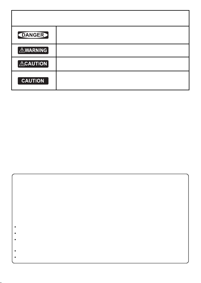
This is the safety alert symbol. It is used to alert you to potential
personal injury hazards, Obey all safety messages that follow this symbol to
avoid possible injury or death.
WARNING indicates a potentially hazardous situation which, if not avoided,
could result in death or serious injury
CAUTION indicates a potentially hazardous situation which, if not avoided, could
result in minor or moderate injury.
CAUTION used without the safety alert symbol indicates a potentially
hazardous situation which, if not avoided, may result in property damage.
DISCLAIMER: It is the owner’s sole
responsibility to install and use the instrument
and transducers in a manner that will not cause
accidents, personal injury or property damage.
The user of this product is solely responsible for
observing safe boating practices.
BRUNSWICK NEW TECHNOLOGIES INC. AND ITS
SUBSIDIARIES AND AFFILIATES DISCLAIM ALL
LIABILIT Y FOR ANY USE OF THIS PRODUCT IN A
WAY THAT MAY CAUSE ACCIDENTS, DAMAGE OR
THAT MAY VIOLATE THE LAW.
Governing Language: This statement,
any instruction manuals, user guides and
other information relating to the product
(Documentation) may be translated to, or
has been translated from, another language
(Translation). In the event of any conf lict
between any Translation of the Documentation,
the English language version of the
Documentation will be the official version of the
Documentation.
This manual represents the Explorer 721
as at the time of printing. Brunswick New
Technologies Inc. and its subsidiaries and
affiliates reserve the right to make changes to
specifications without notice.
Copyright © 2006 Brunswick New Technologies
Inc. Northstar™ is a registered trademark of
Brunswick New Technologies Inc.
FCC Statement
This equipment has been tested and found to comply with the limits for a Class B digital device, pursuant
to Part 15 of the FCC Rules. These limits are designed to provide reasonable protection against harmful
interference in a normal installation. This equipment generates, uses and can radiate radio frequency
energy and, if not installed and used in accordance with the instructions, may cause harmful interference
to radio communications. However, there is no guarantee that interference will not occur in a particular
installation. If this equipment does cause harmful interference to radio or television reception, which
can be determined by turning the equipment off and on, the user is encouraged to try to correct the
interference by one or more of the following measures:
Reorient or relocate the receiving antenna.
Increase the separation between the equipment and receiver.
Connect the equipment into an outlet on a circuit different from that to which the receiver is
connected.
Consult the dealer or an experienced technician for help.
A shielded cable must be used when connecting a peripheral to the serial ports.
2 Northstar Explorer VHF Series: 721US, 721EU Operation and Installation Manual

Contents
Secti on 1 - General Infor mation ............................................................................................................... 6
1-1 Features . . . . . . . . . . . . . . . . . . . . . . . . . . . . . . . . . . . . . . . . . . . . . . . . . . . . . . . . . . . . . . . . . . . . . . . . . . 6
1-2 Customize your Northstar VHF Radio . . . . . . . . . . . . . . . . . . . . . . . . . . . . . . . . . . . . . . . . . . . . .6
1-3 How to Display and Navigate Menus . . . . . . . . . . . . . . . . . . . . . . . . . . . . . . . . . . . . . . . . . . . . . .6
1-4 How to Enter or Change Alphanumeric Data . . . . . . . . . . . . . . . . . . . . . . . . . . . . . . . . . . . . . . 7
1-5 LCD Symbols and Meanings . . . . . . . . . . . . . . . . . . . . . . . . . . . . . . . . . . . . . . . . . . . . . . . . . . . . . . 7
1-6 How the Microphone and Optional Handset Work Together . . . . . . . . . . . . . . . . . . . . . . 9
1-7 Basic Operation and Key Functions . . . . . . . . . . . . . . . . . . . . . . . . . . . . . . . . . . . . . . . . . . . . . .10
Secti on 2 - The Radio Menu (MENU)
2-1 The Radio Menu Options (MENU) . . . . . . . . . . . . . . . . . . . . . . . . . . . . . . . . . . . . . . . . . . . . . . .13
2-2 Show Weather, SNR, or Happy Fish on Handset (INFO DATA) . . . . . . . . . . . . . . . . . . . . . 14
2-3 Maintain Your Buddy List (BUDDY LIST) . . . . . . . . . . . . . . . . . . . . . . . . . . . . . . . . . . . . . . . . . . 15
2-4 Local or Distance Sensitivity (LOCAL/DIST) . . . . . . . . . . . . . . . . . . . . . . . . . . . . . . . . . . . . . .16
2-5 Backlighting (BACKLIGHT) and Contrast (CONTRAST) . . . . . . . . . . . . . . . . . . . . . . . . . . . . 16
2-6 GPS Data and Time (GPS/DATA) . . . . . . . . . . . . . . . . . . . . . . . . . . . . . . . . . . . . . . . . . . . . . . . . . . 17
2-7 GPS Simulator (GPS SIM) . . . . . . . . . . . . . . . . . . . . . . . . . . . . . . . . . . . . . . . . . . . . . . . . . . . . . . . . .20
2-8 Reset to Factory Defaults (RESET) . . . . . . . . . . . . . . . . . . . . . . . . . . . . . . . . . . . . . . . . . . . . . . . .20
Secti on 3 - The Radio Setup Me nu (RADIO SETUP) ..................................................................................... 21
3-1 The Radio Setup Menu Options (RADIO SETUP) . . . . . . . . . . . . . . . . . . . . . . . . . . . . . . . . . .21
3-2 Select the Channel Bank (UIC) . . . . . . . . . . . . . . . . . . . . . . . . . . . . . . . . . . . . . . . . . . . . . . . . . . . 21
3-3 Change Channel Names (CH NAME) . . . . . . . . . . . . . . . . . . . . . . . . . . . . . . . . . . . . . . . . . . . . . 21
3-4 Ring and Beep Volume (RING VOL) and (KEY BEEP) . . . . . . . . . . . . . . . . . . . . . . . . . . . . .22
3-5 Internal Speaker Connections (INT SPEAKER) . . . . . . . . . . . . . . . . . . . . . . . . . . . . . . . . . . . .22
3-6 Set the Priority Channel (WATCH MODE) . . . . . . . . . . . . . . . . . . . . . . . . . . . . . . . . . . . . . . . . . 23
3-7 Weather Alert (Wx ALERT) . . . . . . . . . . . . . . . . . . . . . . . . . . . . . . . . . . . . . . . . . . . . . . . . . . . . . . .23
3-8 NMEA or NAVBUS Protocol (COM PORT) . . . . . . . . . . . . . . . . . . . . . . . . . . . . . . . . . . . . . . . . . 23
3-9 Barometric Displays (BARO SENSOR) . . . . . . . . . . . . . . . . . . . . . . . . . . . . . . . . . . . . . . . . . . . .24
3-10 Temperature Display (TEMPERATURE) . . . . . . . . . . . . . . . . . . . . . . . . . . . . . . . . . . . . . . . . . . 25
Secti on 4 - The DSC Setup Menu (DSC SETUP) ............................................................................................ 26
4-1 The DSC Setup Menu Options (DSC SETUP) . . . . . . . . . . . . . . . . . . . . . . . . . . . . . . . . . . . . . .26
4-2 Check Your User MMSID (USER MMSID) . . . . . . . . . . . . . . . . . . . . . . . . . . . . . . . . . . . . . . . . . .26
4-3 Maintain Your Groups (GROUP SETUP) . . . . . . . . . . . . . . . . . . . . . . . . . . . . . . . . . . . . . . . . . . . 26
4-4 Response to Individual Calls (INDIV REPLY) . . . . . . . . . . . . . . . . . . . . . . . . . . . . . . . . . . . . . . 27
4-5 ATIS MMSID & ATIS Functionality . . . . . . . . . . . . . . . . . . . . . . . . . . . . . . . . . . . . . . . . . . . . . . . . 28
4-6 DSC Functionality (DSC FUNC) . . . . . . . . . . . . . . . . . . . . . . . . . . . . . . . . . . . . . . . . . . . . . . . . . .29
..............................................................................................13
3Northstar Explorer VHF Series: 721US, 721EU Operation and Installation Manual

4-7 Response Type to LL Polling Calls (LL REPLY) . . . . . . . . . . . . . . . . . . . . . . . . . . . . . . . . . . . . .29
4-8 Mute the Notification Ring Tone (LL RING) . . . . . . . . . . . . . . . . . . . . . . . . . . . . . . . . . . . . . . .29
Secti on 5 - Send and Receive DSC C alls ..................................................................................................... 30
5-1 What is DSC? . . . . . . . . . . . . . . . . . . . . . . . . . . . . . . . . . . . . . . . . . . . . . . . . . . . . . . . . . . . . . . . . . . . .30
5-2 The DSC Call Menu Options (DSC CALL) . . . . . . . . . . . . . . . . . . . . . . . . . . . . . . . . . . . . . . . . .30
5-3 Call an Individual (INDIVIDUAL) . . . . . . . . . . . . . . . . . . . . . . . . . . . . . . . . . . . . . . . . . . . . . . . . . . 31
5-4 Call the Most Recent Incoming Call (LAST CALL) . . . . . . . . . . . . . . . . . . . . . . . . . . . . . . . . .32
5-5 Call a Group (GROUP CALL) . . . . . . . . . . . . . . . . . . . . . . . . . . . . . . . . . . . . . . . . . . . . . . . . . . . . . .32
5-6 Call All Ships (ALL SHIPS) . . . . . . . . . . . . . . . . . . . . . . . . . . . . . . . . . . . . . . . . . . . . . . . . . . . . . . . .32
5-7 Call using the Call Log (CALL LOG) . . . . . . . . . . . . . . . . . . . . . . . . . . . . . . . . . . . . . . . . . . . . . . . 33
5-8 Call using the Distress Log (DIST LOG) . . . . . . . . . . . . . . . . . . . . . . . . . . . . . . . . . . . . . . . . . . .33
5-9 Request the LL Position of a Buddy (LL REQUEST) . . . . . . . . . . . . . . . . . . . . . . . . . . . . . . . .34
5-10 Receive an All Ships Call (RCV: ALL SHIPS) . . . . . . . . . . . . . . . . . . . . . . . . . . . . . . . . . . . . . . .35
5-11 Receive an Individual Call (RCV: INDIV) . . . . . . . . . . . . . . . . . . . . . . . . . . . . . . . . . . . . . . . . . .35
5-12 Receive a Group Call (RCV: GROUP) . . . . . . . . . . . . . . . . . . . . . . . . . . . . . . . . . . . . . . . . . . . . .36
5-13 Receive a Geographic Call (RCV: GEOGRAPH) . . . . . . . . . . . . . . . . . . . . . . . . . . . . . . . . . . .36
5-14 Receive a Polled Position Call (RCV: POSITION) . . . . . . . . . . . . . . . . . . . . . . . . . . . . . . . . . . 36
Secti on 6 - Distress Cal ls .......................................................................................................................... 37
6-1 Send a Distress Call . . . . . . . . . . . . . . . . . . . . . . . . . . . . . . . . . . . . . . . . . . . . . . . . . . . . . . . . . . . . . 37
6-2 Receive a Distress Acknowledgement (DISTRESS ACK) . . . . . . . . . . . . . . . . . . . . . . . . . . .37
6-3 Receive a Distress Call (RCV: DISTRESS) . . . . . . . . . . . . . . . . . . . . . . . . . . . . . . . . . . . . . . . . . .38
6-4 Relay a Distress Call (RCV: DISTRESS RELAY) . . . . . . . . . . . . . . . . . . . . . . . . . . . . . . . . . . . . .38
6-5 Relay a Distress Call from the Distress Log (RELAY) . . . . . . . . . . . . . . . . . . . . . . . . . . . . . .38
Append ix A - Technica l Specifications ......................................................................................................39
Append ix B - Troubleshooting ................................................................................................................. 41
Append ix C - VHF Marine Channe l Charts ................................................................................................. 42
Append ix D - MMSID and License Info rmation ......................................................................................... 54
Secti on 7 - Install the Ex plorer 721 .......................................................................................................... 55
7-1 Installation Options . . . . . . . . . . . . . . . . . . . . . . . . . . . . . . . . . . . . . . . . . . . . . . . . . . . . . . . . . . . . .55
7-2 Location Requirements . . . . . . . . . . . . . . . . . . . . . . . . . . . . . . . . . . . . . . . . . . . . . . . . . . . . . . . . . .55
7-3 Checklist . . . . . . . . . . . . . . . . . . . . . . . . . . . . . . . . . . . . . . . . . . . . . . . . . . . . . . . . . . . . . . . . . . . . . . . .55
7-4 Gimbal Installation . . . . . . . . . . . . . . . . . . . . . . . . . . . . . . . . . . . . . . . . . . . . . . . . . . . . . . . . . . . . . .56
7-5 Change the Viewing Angle . . . . . . . . . . . . . . . . . . . . . . . . . . . . . . . . . . . . . . . . . . . . . . . . . . . . .57
7-6 Recessed Installation . . . . . . . . . . . . . . . . . . . . . . . . . . . . . . . . . . . . . . . . . . . . . . . . . . . . . . . . . . . . 57
4 Northstar Explorer VHF Series: 721US, 721EU Operation and Installation Manual

7-7 Install the Microphone Bulkhead Mount . . . . . . . . . . . . . . . . . . . . . . . . . . . . . . . . . . . . . . . . . 58
7-8 Connect the Radio Cables . . . . . . . . . . . . . . . . . . . . . . . . . . . . . . . . . . . . . . . . . . . . . . . . . . . . . . .58
7-9 Set Up the Radio . . . . . . . . . . . . . . . . . . . . . . . . . . . . . . . . . . . . . . . . . . . . . . . . . . . . . . . . . . . . . . . . . 59
7-10 Enter Your User MMSID . . . . . . . . . . . . . . . . . . . . . . . . . . . . . . . . . . . . . . . . . . . . . . . . . . . . . . . . .59
7-11 The Completed Installation (with Optional Handset) . . . . . . . . . . . . . . . . . . . . . . . . . . . .60
Industry Canada
Operation is subject to the following two conditions: (1) this device may not cause interference, and (2)
this device must accept any interference, including interference that may cause undesired operation
of the device.
RF Emissions Notice:
This equipment complies with FCC radiation exposure limits set forth for an uncontrolled environment.
This device’s antenna must be installed in accordance with provided instructions; and it must be operated
with minimum 96 cm spacing between the antennas and all person’s body (excluding extremities of
hands, wrist and feet) during operation. Further, this transmitter must not be co-located or operated in
conjunction with any other antenna or transmitter.
IMPORTANT:
1. Some features described in this manual are not available on every model.
2. DSC functions will not operate on the radio until your user MMSID has been entered. See Section
7.9 for details.
3. The radio channels installed into the radio may vary from country to country, depending upon
the model, and government or national communications authority regulations.
4. Brunswick New Technologies Inc. recommends that you check the radio operating licensing
requirements of your country before using the radio. The operator is solely responsible for
observing proper radio installation and usage practices.
5. A DSC warning label is supplied with the 721US. To comply with FCC regulations, this label must
be affi xed in a location that is clearly visible from the operating controls of this radio. Make sure
that the chosen location is clean and dry before applying this label.
Optional Handset
This manual describes the operation and installation procedures for the Northstar Explorer 721US and
721EU base unit and microphone. An optional Northstar 701US or 701EU handset can be purchased
and installed to give second station operation and intercom facilities.
5Northstar Explorer VHF Series: 721US, 721EU Operation and Installation Manual

Section 1 - General Information
1-1 Fea tur es
Congratulations on your purchase of a Northstar VHF E xplorer 721US or 721EU marine band radio. Both
of these models provide the following useful features:
• Prominent channel display and rotary channel selec tor knob with PRESS TO ENTER function
• Local/Distance mode to eliminate noise in high traffic areas
• Adjustable contrast set tings for the LCD
• Adjustable keypad backlighting for easy night-time use
• Waterproof and submersible to comply with JIS-7
• GPS latitude and longitude (LL) and time display (when connected to a GPS)
• Info key to display barometric data and temperature, or Signal-to-Noise Ratio (SNR)
• Happy Fish symbol that indicates the fishing conditions
• Choice of High or Low (25 W or 1 W) transmission power
• Top centered PTT button for comfortable left- or right-handed use
• Powerful 4 W external audio output
• Access to all currently-available marine VHF channel banks (USA, Canada, International) including
weather channels where available
• Special CH16 or CH16/9 key for quick access to the priority (international distress) channel
• Special 3CH key to select your three favorite channels
• PSCAN (similar to dual watch) facilit y
• DSC (Digital Select Calling) capability that meets USCG SC101 for USA, Class D Standards for
EU/Canada Commercial, and Recreational Class S for Canada
• Distress call key to automatically transmit the MMSID and position until an acknowledgement is
received
• Easy access to a buddy list of up to 20 favorite people
• MMSID storage for three favorite groups
• Group call and All Ships call facility
• LL position polling information and Track Your Buddy facility
• Weather alert facility. 721US only
• ATIS facility for inland water ways. 721EU only
• Alphanumeric microphone for easy, direct channel entry and information editing. 721EU only
• Useful INTERCOM facility if the optional 701US or 701EU handset is installed.
1-2 Customize you r Northstar VHF Radio
You can customize the radio to suit your individual preferences. Some preferences can be set directly through
the keys as explained in this section.
Other preferences are set up through the built-in menus and these are explained in the other sections.
1-3 How to Display and Navigate Me nus
1. Hold down CALL/MENU to show the radio menu
or
Press CALL/MENU to show the DSC call menu.
6 Northstar Explorer VHF Series: 721US, 721EU Operation and Installation Manual
2. Only four menu items can be displayed at any one time on the LCD. Press CH + or CH - to scroll up
and down the menu until the cursor is positioned at the desired option. Press ENT or push the rotary
knob to display that option.
3. Make any entries or changes as explained in the following section.
4. Press ENT or push the rotar y knob to confirm changes. Otherwise, press ESC to keep the original entry.
5. Press ESC to backup one screen or exit. Any changes are active as soon as you exit the screen.
1-4 How to Enter or Chang e Alphanumeric Da ta
If your radio doesn’t have an optional alphanumeric microphone, use the + CH - key to enter
alphanumeric data as follows:
• Press CH - to count through numbers, or hold down to scroll rapidly to the desired number.
• Press CH + to step through the alphabet, or hold down to scroll rapidly to the desired character.
• If you make an error, press CH - until < is displayed, then press ENT or push the rotary knob to
backup and correct the entry.
If your radio has an alphanumeric microphone, use the keypad to enter the cahnngel numbers and
names. Each key has the functionality shown below.
• Use CLR to backup and ENT to confirm, or just wait for the cursor to advance automatically to the
next position when entering data (similar to mobile phone operation),
KEY 0 123456789
Normal and
Menu Mode
Edit Mode
Push 1
Push 2 Space - A D G J M P T W
Push 3 ( . B E H K N Q U X
Push 4 ) “ C F I L O R V Y
Push 5 % / ? ! : # “ S & Z
0 123456789
0 123456789
1-5 LCD Symbols an d Meanings
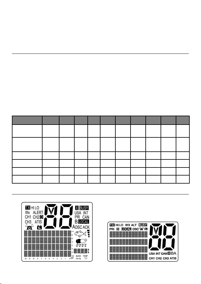
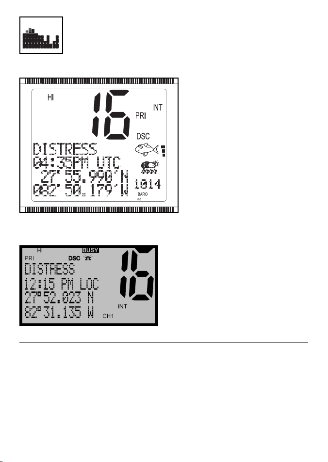
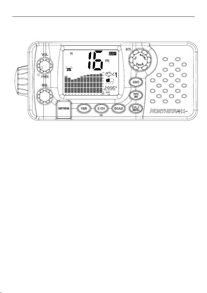
The simulation shows the locations of all the following information symbols on the LCD displays.
Optional handset displayBase unit display
7Northstar Explorer VHF Series: 721US, 721EU Operation and Installation Manual
These symbols may not appear at all or may be shown in a different location on the optional handset.
Symbol Meaning
TX Transmitting.
HI LO Transmission power. High (HI) 25 W or Low (LO) 1 W.
WX Weather channel.
WX ALT Weather Alert. Alarm beeps will sound. 721US only.
BUSY Receiver busy with an incoming signal.
PRI Priority channel is selected.
D Duplex operation. Otherwise, blank for Simplex operation.
LOCAL Local calling is selected. Otherwise, blank for distance calling.
DSC DSC capability is available.
Indicates an incoming DSC call, or blinks to notify you of any unread Call Log
messages
Low Battery warning (activates at 10.5 V)
88 Channel selected.
USA INT CAN Selected channel bank for VHF radio operations and regulations.
X Channel is temporarily deleted from the ALL SCAN operation.
B A Channel suffi x, if applicable.
CH1 CH2 CH3 Shows which of the 3 favorite channels, if any, are selected.
Otherwise blank.
ATIS Enabled for use in European inland waterways. Otherwise blank. 721EU only.
DSC DSC capability is available.
ACK A message acknowledging your DSC call is being displayed.
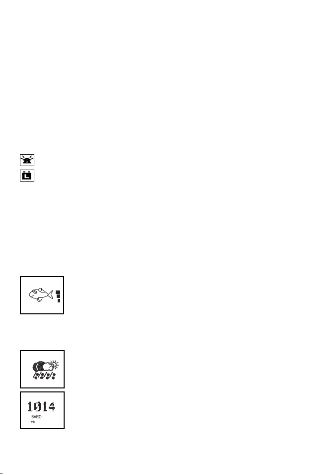
Happy Fish symbol with one to four indicator bars to show the probability of good
fi shing at your current location, based upon barometric pressure and air temperature. Four bars show that good fi shing is likely. High pressure trends are associated
with stable conditions and calm seas. Research indicates that best fi shing occurs
when barometric pressure is rising and between 1010 and 1022 mb. During these
opportune conditions, most fi sh are thought to feed anywhere within the water
column. However, low pressure trends bring stormy seas and aff ect air bladders,
and these conditions make fi sh move to deeper levels and become less active.
Local weather forecast based on the local temperature and stored barometric pres-
sure data. The icons are indicative only and are more accurate close to land rather
than in open sea.
Digital Readout of the current barometric pressure (in mb or in/Hg) or the current
temperature (in ºC or ºF), depending upon your selection.
8 Northstar Explorer VHF Series: 721US, 721EU Operation and Installation Manual
Baro Graph. A histogram of barometric pressure readings over the past 24 hours.
A typical operational display on base unit LCD:
A typical operational display on Optional Handset LCD:
The high-resolution histogram centers automatically if the range goes off scale.
Readouts are taken even when the engine and radio have been powered down
(with typically less than 3mA of current drain).
A transmission on Channel 16 is being
made at high power using the International
channel bank .
Channel 16 is set as the Priority channel.
There is an incoming DSC DISTRESS call so
the receiver is busy.
The latitude and longitude of the vessel
and UTC time are shown.
3 bars by the Happy Fish indicates rising
barometic trends and reasonable fishing
conditions.
The weather indicates shower y conditions.
1-6 How the Micropho ne and Optional Handse t Work Together
If you have the optional handset installed, as well as the microphone:
• neither item works when both are ON hook, but you can hear the audio from the handset
speaker and adjust the handset volume.
• to use one item when it’s OFF hook, the other item must be ON hook.
• if both items are OFF hook, only the microphone works.
• in Intercom mode ONLY, both items work OFF hook.
9Northstar Explorer VHF Series: 721US, 721EU Operation and Installation Manual
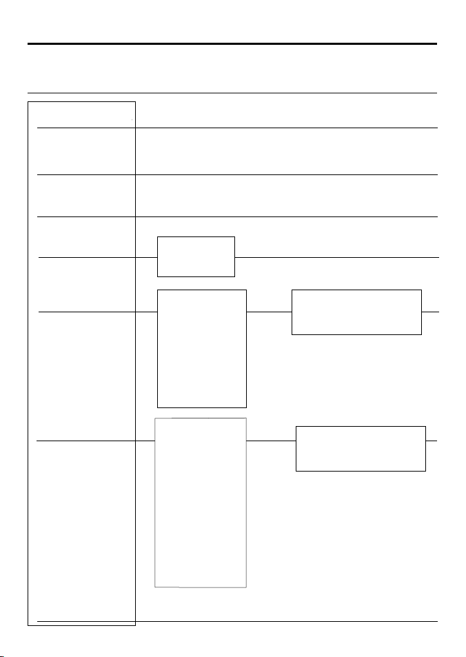
1-7 Basic Operation and Key Func tions
Explorer 721
All possible keys on the base unit, the microphone, and the optional handset are listed and their functions
are explained.
NOTE: Some keys or functions may not be available on your particular model of base unit, microphone, or optional
handset. This example shows the 721US base unit.
Key Function
VOL PWR Volume and Power. Turn clockwise to power on. Continue to turn until a comfortable
SQL Squelch or Threshold Level. Sets the threshold level for the minimum receiver
In areas of high noise (eg close to large cities) reception may improve if sensitivity
DISTRESS Send DSC Distress Call. See Section 6.
16/9 Priority Channel. 721US only. Press to cancel all other modes and to tune into the
The default is Channel 16. To make Channel 09 the priority channel, hold down 16/9
16 Priority Channel. 721EU only. Press to cancel all other modes and to tune into the
3 CH Three Favorite Channels. Press to toggle between your favorite channels. The
To scan only one of your favorite channels, press 3CH then immediately press and
volume is reached. VOL/PWR will also adjust the settings of an external speaker, if
connected.
signal. Turn fully counterclockwise until random noise is heard, then turn slowly
clockwise until the random noise disappears. Make another 1/4 turn clockwise for
best reception in open sea conditions.
is reduced. Either turn SQL slowly clockwise or use the LOCAL setting. See section
2.4.
priority channel. Press again to return to your original channel.
until a beep sounds and 09 is displayed.
priority channel, Channel 16, on high power. Press again to return to your original
channel.
CH1, CH2, or CH3 symbol appears on the LCD to show which favorite channel is
selected.
release SCAN. If you want to scan all three favorite channels, press 3CH then immediately press and hold SCAN.
10 Northstar Explorer VHF Series: 721US, 721EU Operation and Installation Manual

To add a favorite channel for the fi rst time, select that channel then hold 3CH to store
it in the CH1 location. Repeat the procedure to store two more favorite channels in
the CH2 and CH3 locations respectively.
If you try and add another favorite channel it will overwrite the existing CH3. CH1
and CH2 remain unless you delete them.
To delete a favorite channel, select that channel then hold down 3CH until the CH1,
CH2 or CH3 symbol disappears off the LCD.
SCAN Scan. Scanning is not allowed in some European countries. Otherwise, press to
scan between your current channel and the priority channel in DUAL or TRI WATCH
mode. The weather channel is also scanned if the USA channel bank is selected and
the weather alert mode is ON.
Hold down SCAN to enter ALL SCAN mode where the priority channel is checked
every 1.5 seconds.
When a signal is received, scanning stops at that channel and BUSY appears on the
LCD. If the signal stops for more than 5 seconds, the scan restarts.
Press ENT or push the rotary knob to temporarily skip over (lock out) an “always busy”
channel when in ALL SCAN mode and resume the scan. An X is shown on the LCD
to designate a skipped channel. It’s not possible to skip over the priority channel.
Press SCAN to stop at the curr.ent channel.
CALL/MENU Radio Menu, DSC Set up Menu, Radio Set up Menu and DSC CALL Menu.
Hold down to show the radio menu (see Section 2) and to access the radio set up
menu (see Section 3) and the DSC set up menu (see Section 4).
Press to enter the DSC call menu and to make DSC calls (see Section 5).
WX Weather Channel. 721US only. In USA and Canadian waters, press to hear the most
recently selected weather station. The WX symbol is displayed on the LCD.
Press CH + or CH - to change to a diff erent weather channel. Press WX again to
return to the most recent channel.
If the weather alert mode is ON and an alert tone of 1050 Hz is broadcast from the
weather station, it’s picked up automatically and the alarm sounds. Press any key
to hear the weather alert voice message.
IC or H/L IC Intercom. Optional 701US or 701EU handset required. Hold down to enter Intercom mode
on USA models. EU models need just a single press and release.. This disables the radio
receiver except for incoming DSC calls and the intercom calls the other unit.
Press PTT when invited. When you’re fi nished, press ESC to exit Intercom mode or
put the handset back on hook.
ESC Escape. Use ESC when navigating menus, to clear incorrect entries, to exit from a
menu without saving changes, and to back up to the previous screen.
Rotary knob Channel Select. Turn to select a channel. The current channel is shown on the LCD
in BIG digits with an A or B designator suffi x (if applicable) in small letters below the
channel number. (See Appendix C for a listing of channel frequencies.)
Push to activate the ENTER function.
You can also use the rotary knob for alphanumeric entry if you don’t have an alpha-
numeric micrphone. Turn to step through alphanumeric characters one at a time
then push to confi rm each selection. If you make an error, select the < character
then push to backup.
11Northstar Explorer VHF Series: 721US, 721EU Operation and Installation Manual

info Information. Press on the base MIKE to toggle through the INFO display to show
the barometric historgram, the barometric readout and temperature, or the Signalto-Noise Ratio (SNR).
H/L Transmission Power. High (HI) 25 W or Low (LO) 1 W. Press to toggle between high
or low transmission power for the entire channel bank. The HI or LO selection is
shown on the LCD.
Some channels allow only low power transmissions. Error beeps will sound if the
power transmission setting is incorrect.
Some channels allow only low power transmissions initially, but can be changed
to high power by holding down H/L and PTT at the same time. See Appendix C for
a complete listing of channel charts.
+ CH - Channel Select. Press CH + or CH - to step through the available channels one at a
time, or hold down to scroll rapidly through all the available channels. The current
channel is shown on the LCD in BIG digits with an A or B designator suffi x (if applicable) in small letters below the channel number. (See Appendix C for a listing
of channel frequencies.)
Press CH + or CH - to scroll the cursor up and down menu options on the LCD when
navigating menus.
When editing an item containing only numbers, press CH - to step through the
numbers or hold down to scroll rapidly.
To enter a character, press Ch = to step through the alphabet or hold down to scroll
rapidly.
ENT Enter. Press ENT when navigating menus, to confi rm entries and edits.
PTT Press To Talk. Press PTT to transmit at any time on an allowable channel. This auto-
matically exits you from menu mode and stops scanning.
You must release PTT to receive a signal.
If PT T sticks, a built-in timer will automatically shut down a transmission after fi ve
minutes and sound the error beeps. This timer is required by FCC regulations.
12 Northstar Explorer VHF Series: 721US, 721EU Operation and Installation Manual
Section 2 - The Radio Menu (MENU)
I
(
Handset only
)
LO
O
/
A
DSC SETUP
UP
S
ly)
Hold down CALL/MENU to show the radio menu options.
Sections 1-3 and 1-4 explain how to navigate around the menu and enter, save and change data.
2-1 The Radio Menu Options (MENU )
Show weather, SNR or Happy Fish information on the handset.
NFO DATA
See Section 2-2.
BUDDY LIST
CAL/DIST
BACKLIGHT
C
NTRAST
GPS
DAT
RADIO SET
GPS SIM
RE
ET (Base unit on
Maintain your buddy list.
See Section 2-3.
Set backlight level.
See Section 2-5.
MANUAL
SETTING
USER MMSID
GROUP SETUP
INDIV REPLY
DSC FUNC
ATIS MMSID
ATIS FUNC
LL REPLY
UIC
CH NAME
RING VOLUME
KEY BEEP
INT SPEAKER
WATCH MODE
WX ALERT
COM PORT
BARO SENSOR
TEMPERATURE
HAPPY FISH
Turn the GPS Simulator on/off .
See Section 2.7.
(EU only)
(721US only)
(721US only)
Set radio sensitivity.
See Section 2-4.
Set contrast level.
See Section 2-5.
Set position & UTC manually.
See Section 2-6.
Set local time and time format.
See Section 2-6.
DSC SETUP Menu.
See Section 4.
RADIO SETUP Menu.
See Section 3.
Reset factory settings.
See Section 2.8.
13Northstar Explorer VHF Series: 721US, 721EU Operation and Installation Manual

2-2 Show Weather, SNR or Happy Fish on Handset (INFO DATA)
If you have the optional handset installed, you can use INFO DATA to show the local weather forecast
(e.g. SUNNY) and a digital readout of the current barometric pressure (mb or in-Hg) and the channel
name on the handset LCD.
MENU SELECT
>INFO DATA
BUDDY LIST
LOCAL/DIST
INFO DATA
>ON
OFF
After INFO DATA is selected ON, the following screen appears on the handset with Line #3 able to display 3
items of interest - temperature, Signal To Noise ratio (SNR) or HAPPY FISH quality.
• a digital readout of the current air temperature (°F or °C)
• the current Signal-to- Noise Ratio (SNR)
• the Happy Fish symbol with indicator bars.
1. Hold down CALL/MENU to display the radio menu.
2. The cursor is at INFO DATA. Press ENT then select INFO ON to display the information on the handset
LCD, instead of the time and GPS position.
3. 78.4°F is replaced by SNR bars if handset is OFF HOOK.
4. Happy Fish symbol replaces TEMP/SNR if triggered after which it times out.
DISTRESS
A BIT CLOUDY
78.4
°F
29.99in-Hg
14 Northstar Explorer VHF Series: 721US, 721EU Operation and Installation Manual

2-3 Maintain Your Buddy Li st (BUDDY LIST)
Use the Buddy List to store the names and associated MMSIDs of 20 favorite people.
MENU SELECT
>BUDDY LIST
The following sections show to use BUDDY LIST to add, edit, and delete entries in
LOCAL/DIST
BACKLIGHT
Section 3 explains how to call a buddy.
Names are stored in the order of entry, with the most recent entry shown fi rst.
your buddy list.
2-3-1 Add an Entry
BUDDY LIST
> MANUAL NEW
ALEX
TOM
1. Select BUDDY LIST. The cursor is at MANUAL NEW. Press ENT.
2. Enter the buddy name, one character at a time (this may be alphanumeric) then press ENT or push
the rotary k nob repeatedly until the cursor moves to the MMSID entry line.
3. Enter the MMSID (this must be numeric) associated with that buddy name then press ENT.
4. The new buddy name and MMSID are displayed. Press ENT or push the rotary knob to store the new
entry, which is displayed at the top of your buddy list.
NOTE: When the BUDDY LIST is full (20 entries), you can’t make a n ew entry until you have deleted an existi ng
entry
.
ENTER NAME
––––––––––––
ENTER MMSID
–––––––––
ENTER NAME
BOB
ENTER MMSID
123456789
BOB
123456789
> STORE
CANCEL
2-3-2 Edit an Entry
BUDDY LIST
> MANUAL NEW
ALEX
TOM
ALEX
> EDIT
DELETE
EDIT NAME
ALEX
EDIT MMSID
112233445
1. Select BUDDY LIST. Press ENT or push the rotary knob to display the list of entries.
2. Scroll down (if required) to the incorrect entry and press ENT.
3. Select EDIT. The cursor is at the first character of the name.
4. Edit the buddy name or, to edit only the MMSID, press ENT or push the rotary knob repeatedly until
the cursor moves to the MMSID line.
5. When you are finished, press ENT or push the rotary knob (repeatedly if necessary) to display the
next screen.
6. Press ENT or push the rotary knob to store the changes. The buddy list is displayed again. If more
changes are required, repeat Steps 2 thru 6. Otherwise, press ESC to exit.
ALEX
111223344
> STORE
CANCEL
15Northstar Explorer VHF Series: 721US, 721EU Operation and Installation Manual

2-3-3 Delete an En try
BUDDY LIST
> MANUAL NEW
ALEX
TOM
BUDDY LIST
> MANUAL NEW
ALEX
TOM
TOM
> EDIT
DELETE
DELETE BUDDY
TOM
> YES
NO
1. Select BUDDY LIST. Press ENT or push the rotary knob to display the list of entries.
2. Scroll down (if required) to the entry you want to delete and press ENT.
3. Select DELETE then select YES.
4. The entry is deleted immediately and the buddy list is displayed again.
2-4 Local or Distan ce Sensitivity (LOCAL/D IST)
Use LOCAL/DIST to improve the sensitivity of the receiver either locally (LOCAL) or
MENU SELECT
INFO DATA
LOCAL is NOT recommended for use in open sea conditions. It’s designed for use
BUDDY LIST
> LOCAL/DIST
See also SQL (Squelch Control) in Section 1.6.
over distances (DIST).
in areas of high radio noise; e.g. when you’re close to a city.
2-4-1 Set Distance Sensitivi ty
SENSITIVITY
> DISTANT
LOCAL
1. Select LOCAL/DIST then select DIST.
2. Press ENT or push the rotary knob to activate the DIST setting. This disables
local sensitivity and the menu is displayed again.
2-4-2 Set Local Sensitivit y
SENSITIVITY
DISTANT
> LOCAL
LOCAL is displayed on the LCD in reverse video, as a reminder that local sensitivity is selected.
1. Select LOCAL/DIST then scroll to LOCAL.
2. Press ENT or push the rotary knob to activate the LOCAL setting. This disables
distance sensitivity and the menu is displayed again.
2-5 Backlighting (BACKLIGHT ) and Contrast (CONTRAST)
MENU SELECT
LOCAL/DIST
> BACKLIGHT
CONTRAST
16 Northstar Explorer VHF Series: 721US, 721EU Operation and Installation Manual
Use BACKLIGHT to set the backlight levels for the LCD at a comfortable level.
The microphone keypad backlighting is either ON or OFF.
The DISTRESS key backlighting can’t be switched off .
Use CONTRAST to set the contrast level for the LCD.
2-5-1 Set the Backlig hting Level
BACKLIGHT
LO HI
PRESS ENT
1. Select BACKLIGHT.
2. Use CH + or CH - to select a comfortable backlight level.
3. Press ENT or push the rotary knob to confi rm the new level and return to the
menu.
2-5-2 Set the Contrast Le vel
1. Select CONTRAST.
CONTRAST
LO HI
PRESS ENT
2. Use CH + or CH - to select a comfortable contrast level.
3. Press ENT or push the rotary knob to confi rm the new level and return to the
menu.
2-6 GPS Data and Time (GPS/DATA)
MENU SELECT
BACKLIGHT
CONTRAST
> GPS/DATA
This information is important because it will be used if you transmit a DSC distress call.
If your vessel has an operational GPS navigation receiver, the radio automatically
detects and updates the vessel position and the local time.
However, if the GPS navigation receiver is disconnected or absent, you can specify
the vessel position and the local time manually, using the GPS/DATA option.
2-6-1 Manually Ente r Position a nd UTC Time (MANUAL)
NOTE: This function is available only when an operational GPS receiver is NOT connected.
GPS/DATA
> MANUAL
SETTING
1. Select GPS/DATA, then MANUAL.
2. Enter the latitude, then the longitude, then the UTC.
3. Press ENT or push the rotary knob when all the information is correct.
The vessel’s latitude and longitude are shown on the screen, with the UTC time. After entering your
manual LL position, the prefi x “M” in the normal GPS screen indicates a manual entr y. The manual entries
are cancelled if a real GPS position is received.
MANUAL LL
––’ ––’ ––––N
––’ ––’ ––––W
MAN ––:––UTC
17Northstar Explorer VHF Series: 721US, 721EU Operation and Installation Manual
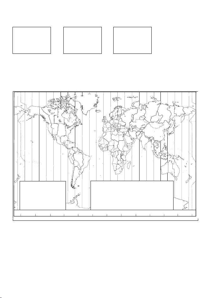
2-6-2 Local Time (TIME OFFSET)
The local time can be set by entering the time off set between UTC and local time as follows.
GPS/DATA
MANUAL
>SETTING
GPS/DATA
> TIME OFFSET
TIME FORMAT
TIME DISPLY
TIME OFFSET
>+01:30
02:30PM LOC
1. Select GPS/DATA, then SETTING.
2. Select TIME OFFSET to enter the diff erence between UTC and local time. Half hour increments can be
used with a maximum off set of ±13 hours.
In this example, a diff erence of +1.5 hours has been entered and the local time is displayed with the
suffi x LOC.
L
L
W
M
Y
X
V
M
V
International Date Line
X
W
M
†
M
M*
*
V
X
W
M
W
*
M
W
M
STANDARD TIME ZONES
Daylight Saving Time (Summer Time),
usually one hour in advance of Standard
Map outline © Mountain High Maps
Compiled by HM Nautical Almanac Office
180°
U
Corrected to January 2005
Zone boundaries are approximate
Time, is kept in some places
150°W
U
U
120°W
Q
S
T
R
S
R
T
S
T
R
S
R
R
S
R
S
S
Q
P
90°W
Z
Q
Q
P
60°W
O
P
‡
P
Z
N
Z
N
Z
Z
P*
Q
P
P
Q
O
N
30°W
A
Z
Z
N
P
A
O
Z
O
Z
m
Z
0
A
+1
B
+2
C
+3
C*
+330
D
+4
D*
+430
E
+5
0°
C D F
A
B
A
B
A
B
B
B
A
C
Z
B
A
E
G
D
E
H
F
C
D
D
F
E
D
*
C
C
C
C
D
C
C
D
H
*
D
E
*
D
F
*
E
F
G
*
E
*
E
E
F
G
F
*
F
B
Standard Time = Universal Time + value from table
h
E*
+530
F
+6
F*
+630
G
+7
H
+8
I
+9
I*
+930
‡
30°E
m
h
m
K
+10
K*
+10 30
L
+11
L*
+11 30
M
+12
M*
+13
M†
+14
No Standard Time legallyadopted
60°E
m
h
N
-1
O
-2
P
-3
P*
-330
Q
-4
R
-5
S
-6
90°E
G
H
K
I
L
M Y
K
L
I
H
I
H
H
H
I
G
H
H
hh
T
-7
U
-8
U*
-830
V
-9
V*
-930
W
-10
X
-11
Y
-12
120°E
M
K
International Date Line
L
I
I
I
I*
m
K
I
K
K
K
150°E
X
M
M
K
L
L
M
L
M
*
L
*
K
M
M
‡
180°
*
18 Northstar Explorer VHF Series: 721US, 721EU Operation and Installation Manual

2-6-3 Time Format Option s (TIME FORMAT)
Time can be shown in 12 or 24 hour format.
GPS/DATA
MANUAL
> SETTING
SETTING
TIME OFFSET
> TIME FORMAT
TIME DISPLAY
TIME FORMAT
> 12 Hr
24 Hr
07:15AM LOC
1. Selec t GPS/DATA, then SETTING.
2. Select TIME FORMAT.
3. Select 12 Hr or 24 Hr as desired. In this example, 12 hour format has been selected so the LCD shows
the AM or PM suffix.
2-6-4 Time Di splay Options (TIME DISPLAY)
If you’ve entered the time manually as described in the previous sections, the time is shown ALWAYS with
the prefi x M.
However, if the vessel’s position is being updated through a GPS navigation receiver, you can switch the time
display ON or OFF as follows:
GPS/DATA
TIME OFFSET
TIME FORMAT
> TIME DISPLY
TIME DISPLY
ON
> OFF
1. Select GPS/DATA, then SETTING.
2. Select TIME DISPLY.
3. Select ON or OFF as desired. In this example,
OFF has been selected and so the LCD no
longer shows the time.
If the time display is set ON, course and speed data are NOT displayed on the LCD (see
section 2-5-6).
2-6-5 Position Dis play Options (LL displa y)
If you’ve entered the vessel position manually as described in the previous section, the vessel position is
shown ALWAYS with the suffi x M.
However, if the time is being updated through a GPS navigation receiver, you can switch the vessel position
display ON or OFF as follows:
GPS/DATA
TIME FORMAT
TIME DISPLY
> LL DISPLAY
LL DISPLAY
ON
> OFF
1. Select GPS/DATA, then SETTING.
2. Select LL DISPLAY.
3. Select ON or OFF as desired. In this example,
OFF has been selected and the screen no
longer shows the vessel position.
2-6-6 Course & Spe ed Display Options (COG/SOG )
Use this option to display course over ground (COG) and speed over ground (SOG) data on the screen.
GPS/DATA
TIME DISPLY
LL DISPLY
> COG/SOG
COG/SOG
> ON
OFF
If COG/SOG is set ON, the time is NOT displayed on the screen (see section 2-5-4).
1. Select GPS/DATA, then SETTING.
2. Select COG/SOG.
3. Select ON or OFF as desired. In this example,
ON has been selected, so the screen shows the
bearing and speed.
19Northstar Explorer VHF Series: 721US, 721EU Operation and Installation Manual
 Loading...