

NorthStar Navigation 701EU, 701US User Manual
Explorer 701US / 701EU Optional Handset
This Installation Sheet is designed to be read with the Explorer 721US and 721EU Operation and Installation Guide. It explains how to
install the optional handset.
Checklist
If anything is missing, consult your dealer.
• Handset with 9.8' (3 m) curly cable attached
• Docking cable 32.8' (10m) (not shown). If you want a diff erent length of docking cable, consult your dealer. Do NOT cut the
docking cable that is supplied.
• Bulkhead mount for the handset (not shown)
• 2 fl at screws for the handset bulkhead mount (not shown)
• 2 self-tapping screws for the handset bulkhead mount (not shown)
• 2 plain washers for the handset bulkhead mount (not shown)
• 2 spring washers for the handset bulkhead mount (not shown)
• 2 nuts for the handset bulkhead mount (not shown)
• Wallplate
• Rubber cushion
• 2 screws for the wallplate
• Protective end cap for the docking cable if handset is disconnected
• Hexagonal nut
BEFORE doing any cutting or drilling, check that:
• the docking cable and the handset curly cable, when connected together, comfortably reach from the base unit to the intended location for the handset wallplate.
• the intended route for the docking cable allows it to be secured to a bulkhead (or similar) along its length.
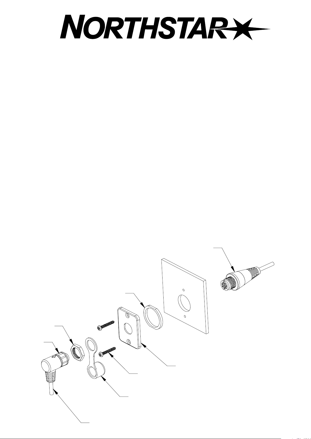
Install the wallplate
1. Hold the wallplate at the chosen location and use a
soft pencil to mark the 2 screw hole positions and
the bulkhead hole position.
2. Drill a 1” (25.4 mm) bulkhead hole and 2 pilot holes
for the screws.
3. Assemble the components as shown.
4. Finger-tighten the locking nut to create a waterproof
connection.
Rubber cushion
Hexagonal nut
Locking nut
Docking cable
Bulkhead with hole drilled
Wallplate
Screw
Handset curly cable
Protective end cap
Install the handset bulkhead mount
M84
1. Hold the handset bulkhead mount at the chosen location and use a soft pencil to mark the 2 screw hole positions.
2. Drill 2 pilot holes for the screws.
3. Screw the handset bulkhead mount to the chosen location using the screws, nuts and washers provided.
4. Hang the handset on the bulkhead mount.
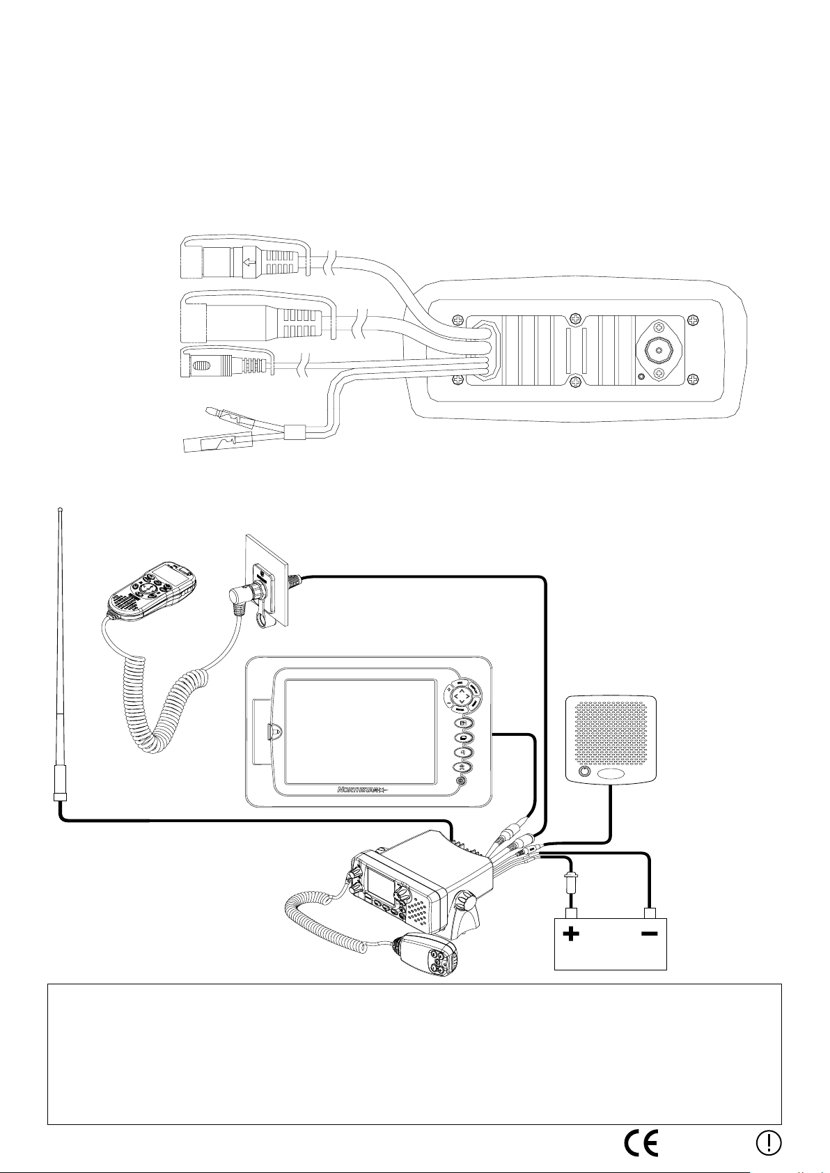
Connect the docking cable to the radio
1. Locate the handset connector at the rear of the radio.
2. Take the protective end cap off of the handset connector, then push the end of the docking cable into the handset connector.
Handset connector
Example of a completed installation with a Northstar Explorer 721
Wallplate on
bulkhead
Handset
M84
Other Northstar
product
VHF Antenna
Antenna connection cable
Handset docking cable
External speaker
connection cable
Fuse on RED
power cable
External speaker
BLACK power
cable
Base unit with
microphone
Battery
It is the owner’s sole responsibility to install and use the instrument in such a manner that will not cause accidents, personal injury or property
damage.
Brunswick New Technologies Inc. and its subsidiaries and affiliates disclaim all liability for any use of this product in a way that may
cause accidents, damage or that may violate the law.
Governing Language: This statement, any instruction manuals, user guides and other information relating to the product (Documentation)
may be translated to, or has been translated from, another language (Translation). In the event of any conflict between any Translation of
Documentation, the English language version of the Documentation will be the official version of the Documentation.
This manual represents the product at the time of printing. Brunswick New Technologies Inc. and its subsidiaries and affiliates reserve the right
to make changes to specifications without notice.
Copyright © 2006 Brunswick New Technologies Inc. Northstar™ is a registered trademark of Brunswick New Technologies Inc.
LA000663A-G
0560
 Loading...