

491 E
CHO
S
OUNDER
I
NSTALLATION
Part Number GM495
Northstar
a unit of Brunswick New Technologies Marine Electronics
30 Sudbury Road
Acton, Massachusetts 01720
Rev A
M
ANUAL
www.NorthstarNav.com
Service: 978/897-6600
Sales: 800/628-4487


Table of Contents
SECTION ONE — Introduction
Welcome to the Northstar 491
Who should read this manual
Scope of this manual
Installation considerations
- - - - - - - - - - - - - - - - - - - - 1
- - - - - - - - - - - - - - - - - 1
- - - - - - - - - - - - - - - - - 1
- - - - - - - - - - - - - - - - - - - - - 1
- - - - - - - - - - - - - - - - - - - 2
SECTION TWO — Installing the transducer
Safety considerations
Selecting a transducer
Installation considerations
Choosing a mounting location
Installing the transducer
Maintaining the transducer
SECTION THREE — Installing the 491
Safety considerations
System components
Choosing a mounting location
Mounting the 491
Wiring the 491
Initial checkout
Installation test checklist
- - - - - - - - - - - - - - - - - - - - - 3
- - - - - - - - - - - - - - - - - - - - - 4
- - - - - - - - - - - - - - - - - - - 5
- - - - - - - - - - - - - - - - - 5
- - - - - - - - - - - - - - - - - - - - 7
- - - - - - - - - - - - - - - - - - 8
- - - - - - - - - - - - - - - 11
- - - - - - - - - - - - - - - - - - - - 11
- - - - - - - - - - - - - - - - - - - - - 13
- - - - - - - - - - - - - - - - 14
- - - - - - - - - - - - - - - - - - - - - - 14
- - - - - - - - - - - - - - - - - - - - - - - 15
- - - - - - - - - - - - - - - - - - - - - - - 19
- - - - - - - - - - - - - - - - - - 20
- - - - - - - - - - - - - - 3
SECTION FOUR — Troubleshooting and servicing the 491
Common 491 installation problems
The status LED
Getting technical support
Ordering replacement parts
Servicing the 491
Returning a 491 for service
- - - - - - - - - - - - - - - - - - - - - - - 21
- - - - - - - - - - - - - - - - - - 24
- - - - - - - - - - - - - - - - - 25
- - - - - - - - - - - - - - - - - - - - - - 25
- - - - - - - - - - - - - - - - - 26
APPENDIX A — Technical specifications
Glossary
Index
- - - - - - - - - - - - - - - - - - - - - - - - - - - - - 29
- - - - - - - - - - - - - - - - - - - - - - - - - - - - - - - 31
- - - - - - - - - - - - - - 21
- - - - - - - - - - - - - - 27
- - - - - - 21


SECTION ONE — Introduction
Welcome to the Northstar 491
An echo sounder is a device that provides information about the water
directly beneath a vessel. The Northstar echo sounder system consists of:
•
the Northstar 491 echo sounder sensor
•
a Northstar navigation system such as the 962, 958 or 6000i
•
a transducer
The 491 can be used with either a single-element transducer or a
dual-element transducer. The 491 automatically pings both transmitters
at power-up to determine the number of transducer elements connected.
If a single element is detected, the 491 operates in single-frequency or
dual-frequency interleaved mode (as determined by the operator) at 600
Watts. If two elements are detected, the 491 uses both elements at 1000
Watts.
Installation and setup procedures are different for the two basic types of
Northstar navigators. The following terminology should be carefully followed:
•
the term 961/962 indicates instructions that apply to the Northstar
961 and the 962 navigators
•
the term 957/958/6000i is used for these units
•
the term navigator by itself identifies information that applies to all
units
Who should
read this
This manual is for marine technicians who are installing the Northstar
491 and connecting it to a Northstar navigator and a transducer.
manual
Scope of this manual
491 INSTALLATION MANUAL Revision A PAGE 1
In this manual, you’ll find information about the following:
•
mounting and wiring the 491
•
connecting the 491 to the Northstar navigator
•
installing a transducer (an overview is provided, but for such details
as wiring, see the documentation provided by the transducer’s manufacturer)
SECTION ONE — Introduction
Installation
•
connecting the 491 to a transducer (see also the Transducer Connec-
tor Instructions —GM492)
•
troubleshooting and testing the system
•
technical specifications for the 491
For information about obtaining technical support and returning the 491
for factory service, “SECTION FOUR — Troubleshooting and servicing the
491” beginning on page 21.
For details about operating the 491, see the Northstar 491 Echo Sounder
Operations Manual (GM494) or Northstar 6000i’s Reference Manual, for
that product.
considerations
CAUTION!
1. Check the shipping carton for any damage, and immediately report
any damage to the carrier. Save all packing material in case you have
to return the 491 to the factory for repair or evaluation.
2. Unpack the carton, and check its contents. You should have
received:
•
the Northstar 491 Echo Sounder
•
10-foot (3-meter) data cable to connect the 491 to the navigator
•
10-foot (3-meter) power cable for the 491
•
491 parts kit (containing transducer cable end connector, backshell, heatshrink tubing, and the Transducer Connector Instruc-
tions —GM492)
•
Northstar 491 Echo Sounder Installation Manual (GM495)
•
Northstar 491 Echo Sounder Operations Manual (GM494)
•
owner registration card
3. Fill out the owner registration card and mail it to Northstar.
4. Review all of the installation requirements as outlined in Sections
Two and Three.
5. Install the transducer, then terminate the cable (see ”Connecting the
491 to a transducer” starting on page 18).
6. Mount the 491. For instructions, see ”Mounting the 491” beginning
on page 14.
7. Connect the 491 to ship’s power and to the navigator. Connection
information begins on page 15.
With the vessel in the water, turn on the system and verify proper operation.
The following list of installation considerations isn’t
a substitute for all the details in Section Three. To
ensure that you meet all critical installation parameters, be sure to read that entire section and follow
all of its recommendations.
PAGE 2 491 INSTALLATION MANUAL Revision A
SECTION TWO — Installing the transducer
Safety considerations
WARNING!
Be sure to turn the power off before starting the
installation. Further, it is highly recommended that
you keep power off while you’re performing the
installation. If power is left on or turned on during
the installation, fire, electrical shock, or other serious injury may occur.
Be sure to ground the equipment to prevent electrical shock and mutual interference.
WARNING!
CAUTION!
Be sure the transducer outputs are tied together
before handling to avoid electrical charge build-up.
Be sure to use a 3-amp fuse. Using the incorrect
fuse can result in fire or damage to the 491.
Mounting the transducer requires drilling holes
through the hull; make sure the installation does
not cause the vessel to leak. A thru-hull installation
should be performed by a professional installer. Do
not attempt this unless you are fully qualified.
Do not perform a thru-hull installation of the transducer when the vessel is actually in the water.
Immediately after installing the transducer, be sure
to check for leaks, and don’t leave the vessel in the
water for more than three hours before checking it
again.
Northstar assumes no responsibility for improper
installation of a transducer.
NOTE:
491 INSTALLATION MANUAL Revision A PAGE 3
Be sure that the transducer doesn’t interfere with
any of the on-board systems. Check all other systems to ensure that their performance doesn’t
degrade when the transducer is connected.

SECTION TWO — Installing the transducer
Selecting a transducer
Manufacturer Housing Power Frequency Northstar P/N
Airmar B260 1 kW 50/200 kHz TD1004
Airmar B744V/B44V (with
Airmar P66 600 W 50/200 kHz TD1006
Transducer
element
Northstar recommends using an Airmar transducer with the Northstar
491 echo sounder. The Airmar B260, B744 and P66 can be obtained from
Northstar as an installation kit with connectors installed.
Table 1: Northstar-recommended transducers
600 W 50/200 kHz TD1005
3-wire speed)
A table of Airmar transducer elements is given below to assist in evaluating characteristics of other Airmar transducers.
Table 2: Airmar transducer elements
Single
or Dual
element
Used in
Airmar
P/N
Acoustic
material
Beam
Width
(50
kHz)
Beam
Width
(200 kHz)
Rated
Power
50/200A Single B744V
B744VL
P319
B117
SS555
50/200A Single P66
P79
P74
50/200B Single B256 Urethane 23° 5° 1200W
50AE/200Riq Dual B45
B250-B
B260
Dealers can also purchase quantities of transducers directly from Airmar
Technology Corporation at:
Milford, New Hampshire 03055-4613
Urethane 45° 12° 600W
LPU 45° 11° 600W
Urethane 19° 6° 1000W
Airmar Technology Corporation
35 Meadowbrook Drive
Phone 603/673-9570
Fax 603/673-4624
(www.airmar.com)
PAGE 4 491 INSTALLATION MANUAL Revision A
SECTION TWO — Installing the transducer
Installation considerations
Choosing a mounting location
The following basic setup information isn’t a substitute for the installation instructions provided by the transducer’s manufacturer. To ensure
that you meet all critical installation parameters, be sure to read and follow all of the requirements in their instructions. Northstar assumes no
responsibility for improper installation.
CAUTION!
The two most common problems with echo sounder installations stem
from electrical noise and cavitation . Either of these situations can produce
poor performance.
Do not mount the transducer:
behind strakes, fittings, or hull irregularities (mounting in those locations may increase turbulence, aeration, and cavitation) or near the keel
near openings for water intake or discharge
where it might be loosened by the vessel’s vibration
less than four feet away from the Northstar 961/962
processor or other similar equipment to minimize
interference
Choose the mounting
location to obtain the best
possible performance from
the transducer and the 491.
Take into account the
vessel’s maximum speed
when selecting a mounting
location, as turbulence can
affect echo sounding
capabilities.
Electrical noise occurs when the transducer cable is routed too closely to
noise-producing electronics, such as alternators, AC generators, radars,
etc. To avoid problems with noise, route the transducer cable by itself
(not in a bundle) and away from other wires or cables and the engine.
Cavitation can occur at high speeds. During cavitation, bubbles form
between the transducer and the water. When this happens, the transducer can’t get its energy into the water properly and won’t be able to
detect any echoes. To avoid cavitation, choose a mounting location with
good water flow all around it at all speeds.
Before any drilling or cutting takes place, carefully choose a mounting
location for the transducer that meets the following criteria (also see
Figure 1 on page 7), depending on the type of vessel:
•
the transducer is more than four feet away from the Northstar navigator and other similar equipment, to prevent mutual electrical and
magnetic interference
• the transducer and its cable are as far as possible from other electri-
cal cables
• there is space above the transducer for the transducer’s stem, hous-
ing, and cable
491 INSTALLATION MANUAL Revision A PAGE 5

SECTION TWO — Installing the transducer
• the path for running the transducer’s cable is reasonably direct—keep
in mind that the transducer cable is 33 feet long (10 meters). To prevent damage, coil any excess cable and secure it
• water turbulence and noise are minimal, decreasing the amount of
bubbles passing over the transducer face
• the transducer isn’t behind hull irregularities or near eroding paint;
both indicate areas subject to turbulence
• the transducer is as far as possible from the engine or propellers, and
inboard of the lifting strakes
• the transducer always remains submerged and parallel to the water
surface
• the transducer is easily accessible from inside the vessel for adjust-
ments and maintenance
• the transducer’s ultrasonic beams aren’t obstructed by the keel, pro-
peller shafts, or any other part of the vessel
• the hull thickness falls within the limits in Table 3 below (all dimen-
sions are perpendicular to the waterline):
Table 3: Hull thickness limits
Model Minimum Maximum
AirMar B44V/B744V with fairing 6 mm (1/4 inch) 19 mm (3/4 inch)
AirMar B44V/B744V without fairing 6 mm (1/4 inch) 65 mm (2 1/2 inches)
AirMar B260 with fairing —— 45 mm (1 3/4 inches)
AirMar B260 without fairing 19 mm (3/4 inch) 114 mm (4 1/2 inches)
PAGE 6 491 INSTALLATION MANUAL Revision A
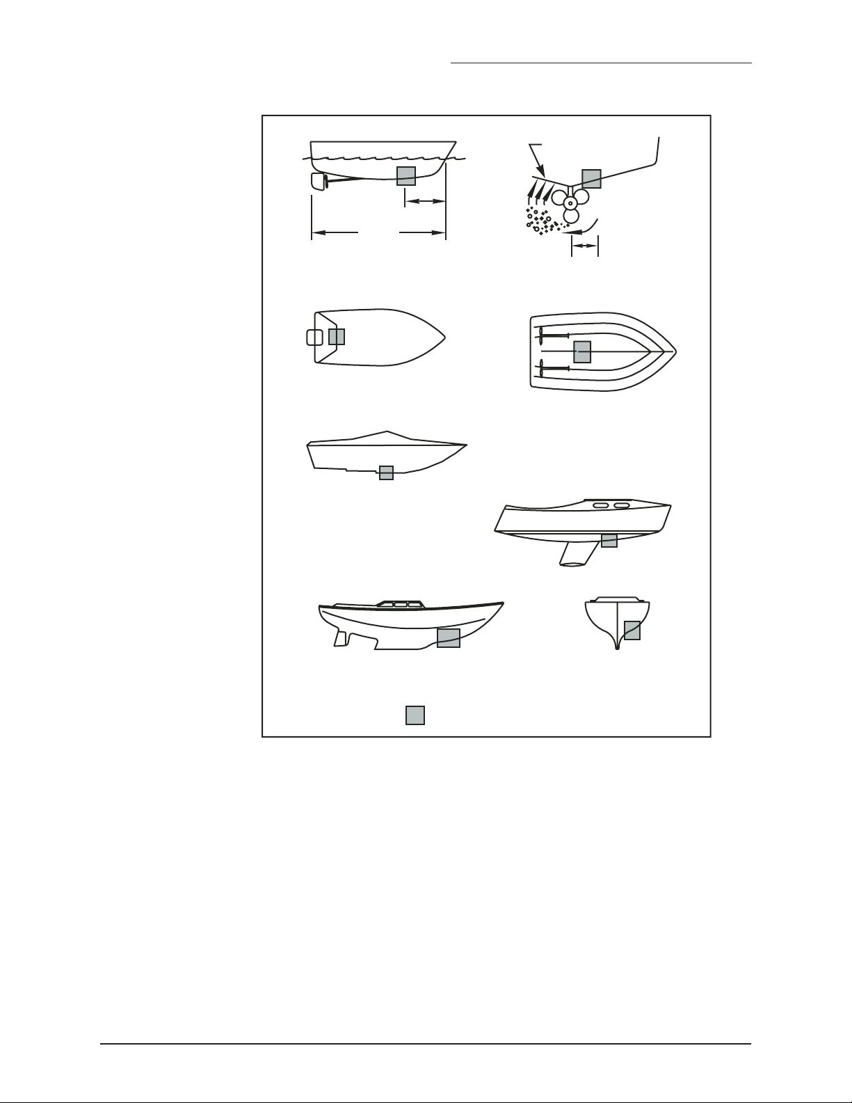
1/3 aft
LWL
(Load Waterline Length)
outboard and I/O
SECTION TWO — Installing the transducer
displacement hull
planning hulls
pressure waves
150-300mm
(6-12")
inboard
Installing the transducer
step-hull
fin keel sailboat
full keel sailboat
Best location for the transducer
FIGURE 1: Recommended installation locations for a transducer
A flat-bottom hull provides the best environment for mounting the transducer: It provides a horizontal surface and a constant water flow over the
transducer, with little turbulence (see Figure 2 for the recommended
transducer incline angle). If the vessel has a deadrise angle greater than 5
degrees, mount the transducer on a fairing block to create a horizontal
surface and keep the transducer perpendicular to the waterline (see
Figure 3). You must order the fairing block, if needed, from the transducer’s manufacturer.
491 INSTALLATION MANUAL Revision A PAGE 7

SECTION TWO — Installing the transducer
3˚ incline
angle
1/3 aft
LWL
(Load Waterline Length)
FIGURE 2: Recommended transducer incline angle
backing
block
hull
fairing thickness
at narrowest point
6– 12 mm (1/4–1/2")
slope of hull
parallel to
waterline
fairing
multisensor
deadrise
angle
Maintaining the transducer
Using anti-fouling
paint
Deadrise angle and fairing thickness (B44V shown)
FIGURE 3: Typical finished thru-hull installation with a fairing
block (Airmar B744V)
Do not expose the transducer’s face or plastic housing to gasoline or
strong solvents, such as acetone. These solvents can penetrate and
degrade many plastics and reduce their strength.
The transducer should be coated with water-based anti-fouling paint to
prevent aquatic growth.
PAGE 8 491 INSTALLATION MANUAL Revision A
 Loading...