

www.nordictrack.com
Model No. 831.21977.0
Serial No.
Write the serial number in the
space above for reference.
Serial Number
QUESTIONS?
,0 PRO
USER'S MANUAL
Decal
If you have questions, or if parts
are damaged or missing, DO NOT
CONTACT THE STORE; please
contact Customer Care.
IMPORTANT: Please register this
product (see the limited warranty
on the back cover of this manual)
before contacting Customer Care.
CALL TOLL-FREE:
1-800-TO-BE-FIT
(1-800-862-3348)
Mon.-Fri. 6 a.m.-6 p.m. MT
Sat. 8 a.m.-4 p.m. MT
ON THE WEB:
www.nordictrackservice.com
__wlw_F R E E "_
/f_ HOW-TO /
_rl I_ k_)V,DEOS /
.iFit.com _'
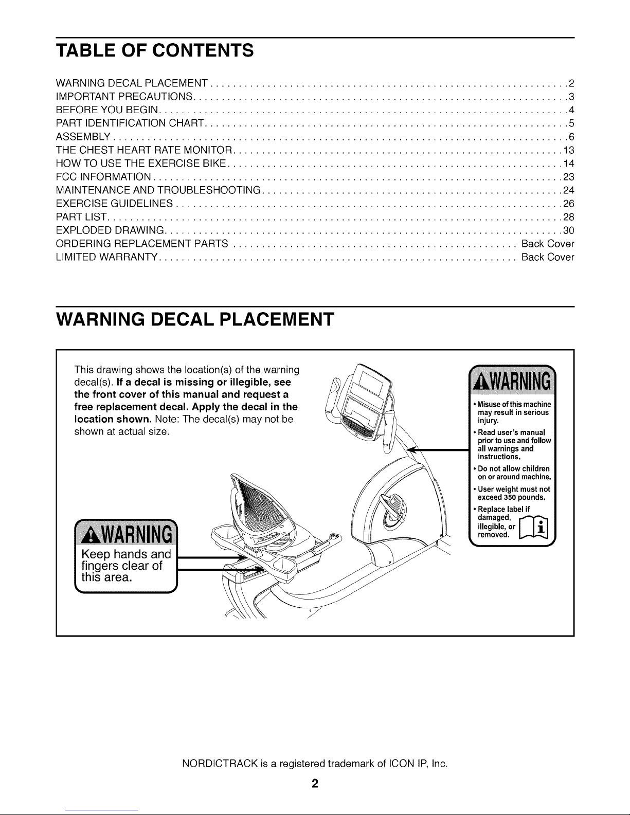
TABLE OF CONTENTS
WARNING DECAL PLACEMENT ............................................................... 2
IMPORTANT PRECAUTIONS .................................................................. 3
BEFORE YOU BEGIN ........................................................................ 4
PART IDENTIFICATION CHART ................................................................ 5
ASSEMBLY ................................................................................ 6
THE CHEST HEART RATE MONITOR .......................................................... 13
HOW TO USE THE EXERCISE BIKE ........................................................... 14
FCC INFORMATION ........................................................................ 23
MAINTENANCE AND TROUBLESHOOTING ..................................................... 24
EXERCISE GUIDELINES .................................................................... 26
PART LIST ................................................................................ 28
EXPLODED DRAWING ...................................................................... 30
ORDERING REPLACEMENT PARTS .................................................. Back Cover
LIMITED WARRANTY ............................................................... Back Cover
WARNING DECAL PLACEMENT
This drawing shows the location(s) of the warning
decal(s). If a decal is missing or illegible, see
the front cover of this manual and request a
free replacement decal. Apply the decal in the
location shown. Note: The decal(s) may not be
shown at actual size.
• Misuseof thismachine
may result inserious
injury.
• Read user'smanual
priorto useandfollow
allwarnings and
instructions.
• Donot allowchildren
on oraroundmachine.
• Userweight must not
exceed350 pounds.
• Replacelabel if
illegible,or
removed.
damaged, [_
NORDICTRACK is a registered trademark of ICON IP, Inc.
2
IMPORTANT PRECAUTIONS
3
BEFORE YOU BEGIN
Thank you for selecting the revolutionary
NORDICTRACK <R_"GX 7.0 PRO exercise bike. Cycling
is an effective exercise for increasing cardiovascular
fitness, building endurance, and toning the body. The
GX 7.0 PRO exercise bike provides an impressive
selection of features designed to make your workouts
at home more effective and enjoyable.
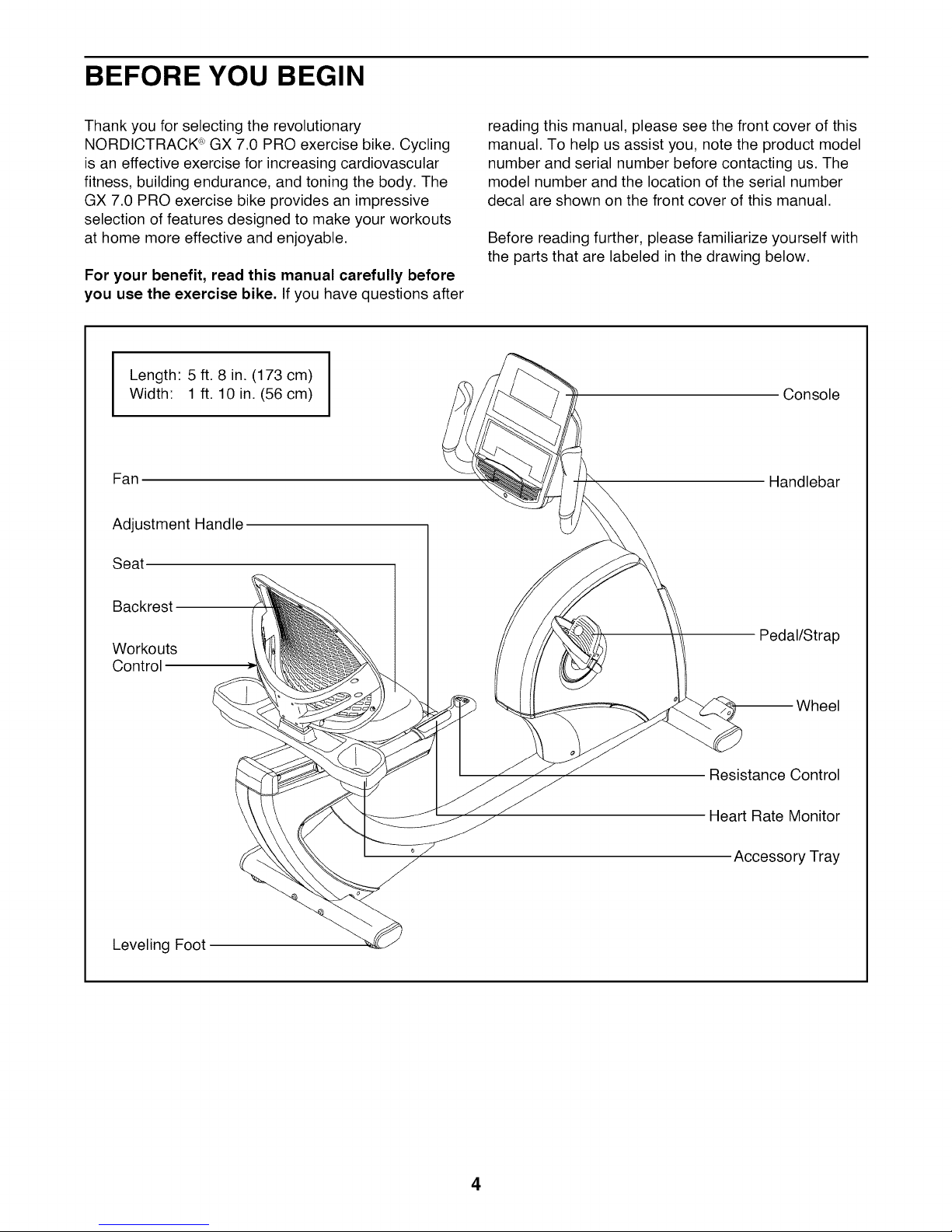
For your benefit, read this manual carefully before
you use the exercise bike. If you have questions after
Length: 5 ft. 8 in. (173 cm)
Width: 1 ft. 10 in. (56 cm)
Fan
Adjustment Handle
Seat
reading this manual, please see the front cover of this
manual. To help us assist you, note the product model
number and serial number before contacting us. The
model number and the location of the serial number
decal are shown on the front cover of this manual.
Before reading further, please familiarize yourself with
the parts that are labeled in the drawing below.
Console
Handlebar
Backrest
Workouts
Control
Leveling Foot
Pedal/Strap
_el
Resistance Control
Heart Rate Monitor
Accessory Tray
4
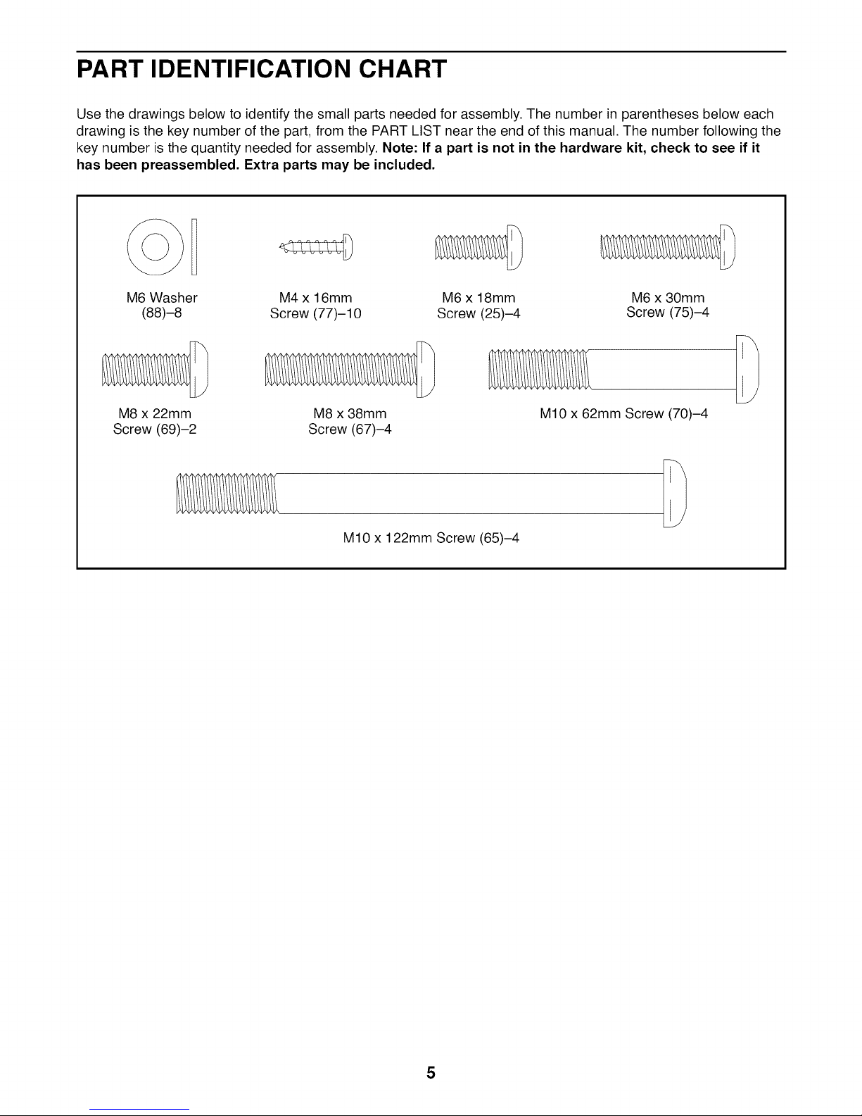
PART IDENTIFICATION CHART
Use the drawings below to identify the small parts needed for assembly. The number in parentheses below each
drawing is the key number of the part, from the PART LIST near the end of this manual. The number following the
key number is the quantity needed for assembly. Note: If a part is not in the hardware kit, check to see if it
has been preassembled. Extra parts may be included.
M6 Washer
(88)-8
M8 x 22mm
Screw (69)-2
M4 x 16mm M6 x 18mm M6 x 30mm
Screw (77)-10 Screw (25)-4 Screw (75)-4
M8 x 38mm
Screw (67)-4
M10 x 122mm Screw (65)-4
M10 x 62mm Screw (70)-4
5
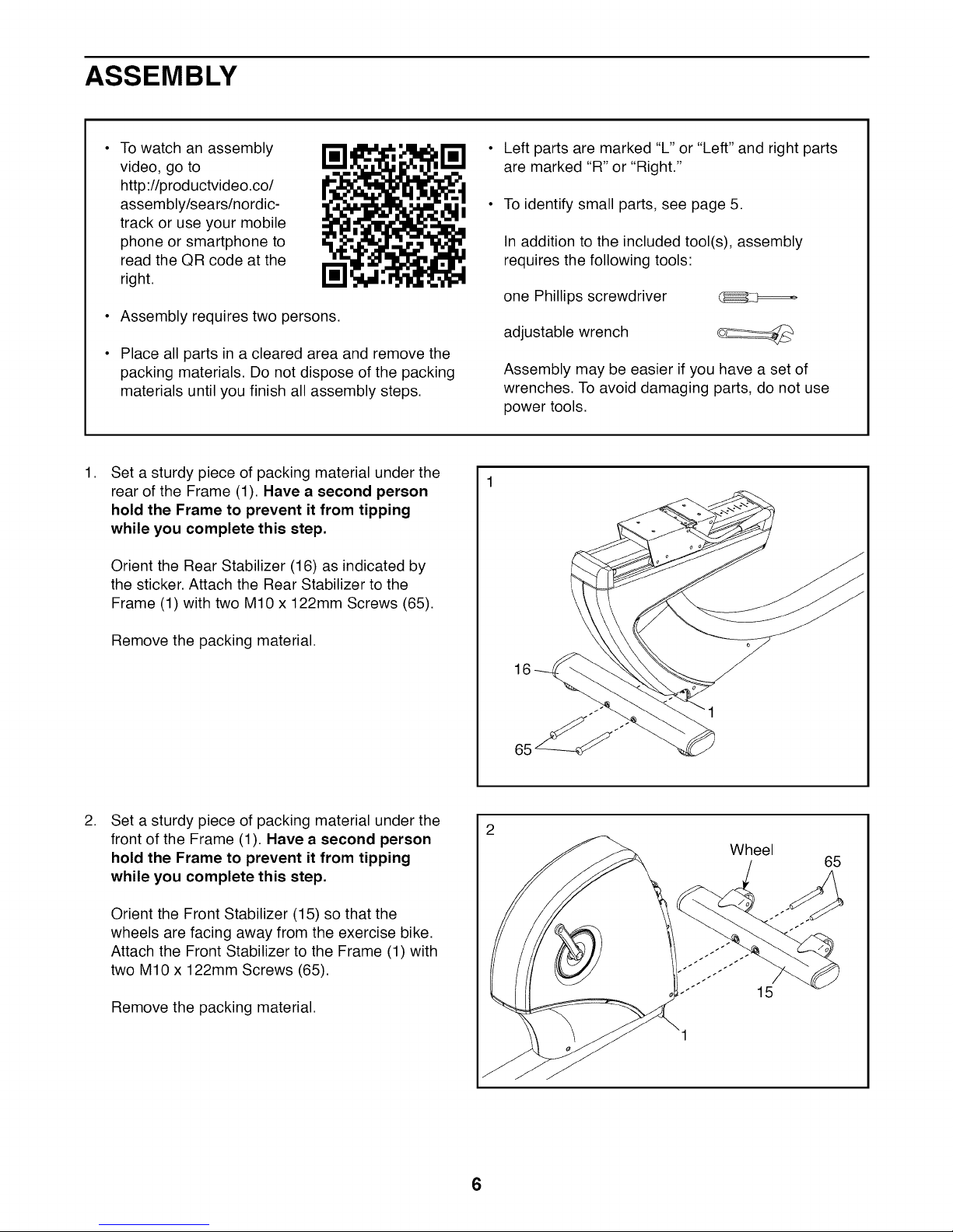
ASSEMBLY
To watch an assembly
video, go to
http://productvideo.co/
assembly/sears/nordic-
track or use your mobile
phone or smartphone to
read the QR code at the
right.
Assembly requires two persons.
Place all parts in a cleared area and remove the
packing materials. Do not dispose of the packing
materials until you finish all assembly steps.
,
Set a sturdy piece of packing material under the
rear of the Frame (1). Have a second person
hold the Frame to prevent it from tipping
while you complete this step.
Orient the Rear Stabilizer (16) as indicated by
the sticker. Attach the Rear Stabilizer to the
Frame (1) with two M10 x 122mm Screws (65).
Left parts are marked "L" or "Left" and right parts
are marked "R" or "Right."
To identify small parts, see page 5.
In addition to the included tool(s), assembly
requires the following tools:
one Phillips screwdriver (_
adjustable wrench
Assembly may be easier if you have a set of
wrenches. To avoid damaging parts, do not use
power tools.
Remove the packing material.
,
Set a sturdy piece of packing material under the
front of the Frame (1). Have a second person
hold the Frame to prevent it from tipping
while you complete this step.
Orient the Front Stabilizer (15) so that the
wheels are facing away from the exercise bike.
Attach the Front Stabilizer to the Frame (1) with
two M10 x 122mm Screws (65).
Remove the packing material.
2
Wheel
65
15
6

Orient the Upright (2) as shown. Have a second
3. 3
person hold the Upright near the front of the
Frame (1).
Tie the lower end of the wire tie in the Upright
(2) to the Main Wire (43), to the Frame Pulse
Wire (42), and to the Extension Wire (86) in the
Frame (1).
Pull the upper end of the wire tie until the wires
are routed through the Upright (2).
Wire Tie
Wire Tie
43
42
\
\
\
,
Tip: Avoid pinching the wires. Slide the
Upright (2) onto the Frame (1)
Attach the Upright (2) with four M10 x 62mm
Screws (70); start all the Screws, and then
tighten them.
4
Avoid pinching
the wires
7
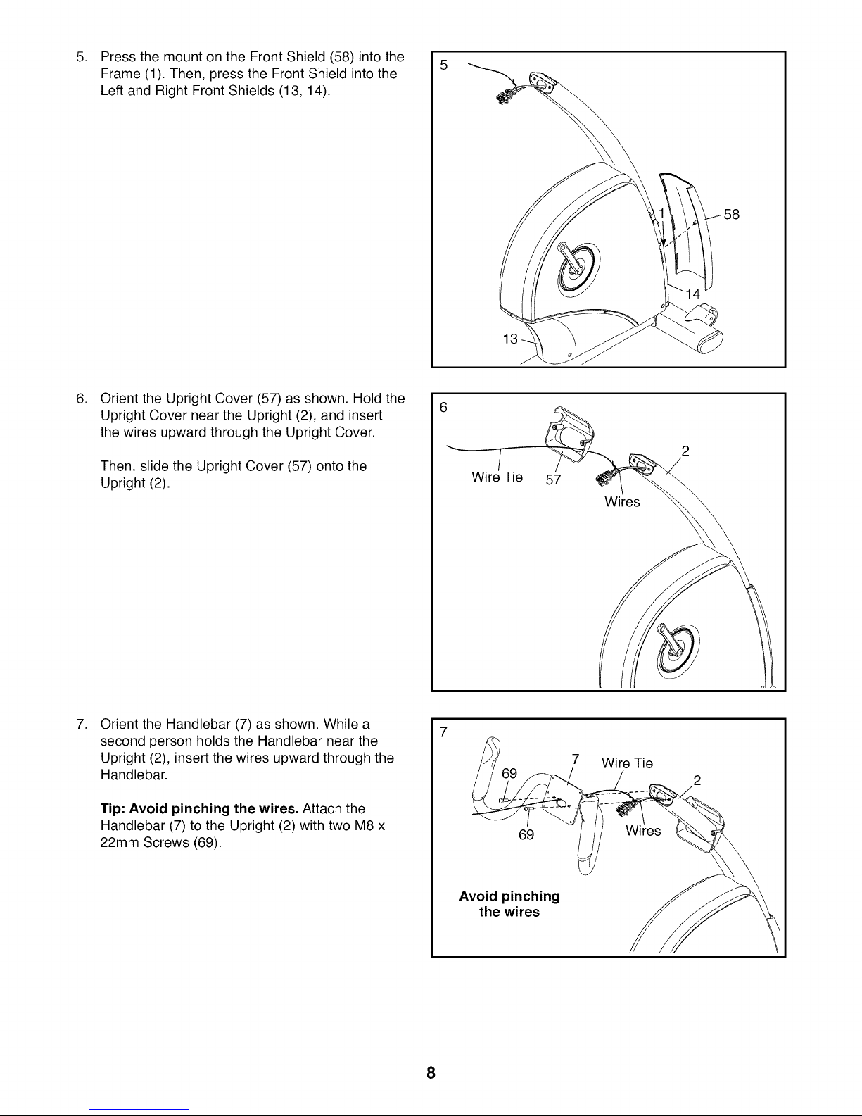
Press the mount on the Front Shield (58) into the
5. 5
Frame (1). Then, press the Front Shield into the
Left and Right Front Shields (13, 14).
,
Orient the Upright Cover (57) as shown. Hold the
Upright Cover near the Upright (2), and insert
the wires upward through the Upright Cover.
6
Then, slide the Upright Cover (57) onto the
Upright (2).
,
Orient the Handlebar (7) as shown. While a
second person holds the Handlebar near the
Upright (2), insert the wires upward through the
Handlebar.
Tip: Avoid pinching the wires. Attach the
Handlebar (7) to the Upright (2) with two M8 x
22mm Screws (69).
7
/
Wire Tie
57
Wires
7 Wire Tie
69
Avoid pinching
the wires
8
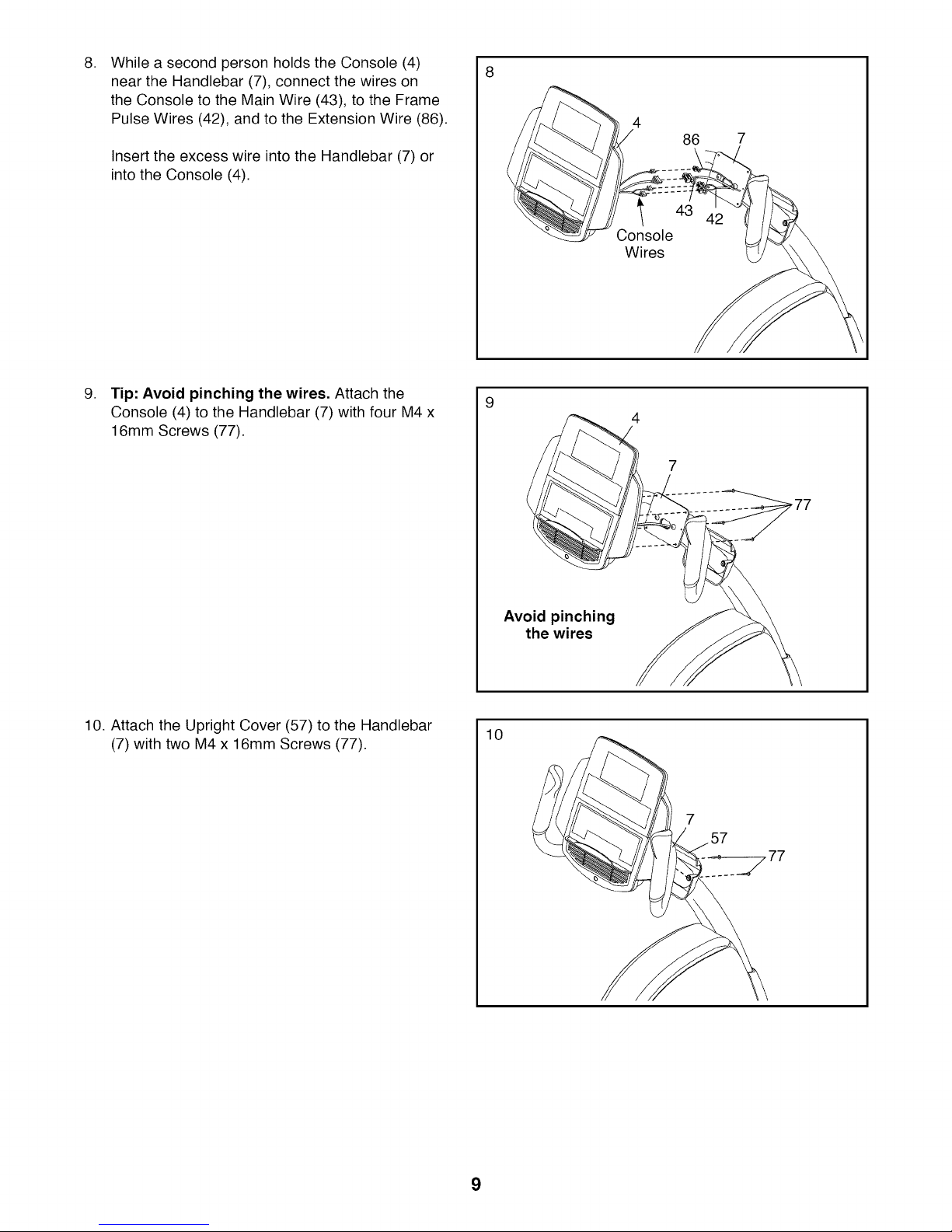
While a second person holds the Console (4)
8. 8
near the Handlebar (7), connect the wires on
the Console to the Main Wire (43), to the Frame
Pulse Wires (42), and to the Extension Wire (86).
Insert the excess wire into the Handlebar (7) or
into the Console (4).
,
Tip: Avoid pinching the wires. Attach the
Console (4) to the Handlebar (7) with four M4 x
16mm Screws (77).
4
86
Console
Wires
9
4
10. Attach the Upright Cover (57) to the Handlebar
(7) with two M4 x 16mm Screws (77).
Avoid pinching
the wires
10
9
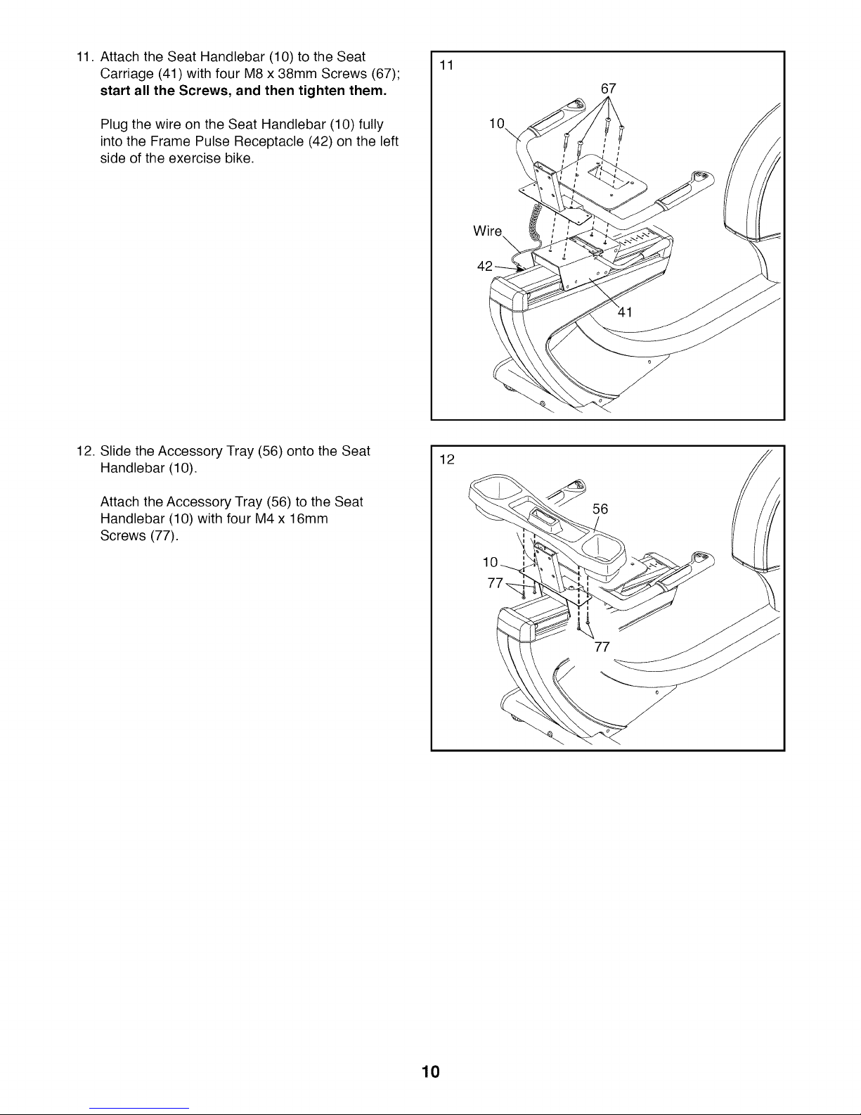
11. Attach the Seat Handlebar (10) to the Seat
Carriage (41) with four M8 x 38mm Screws (67);
start all the Screws, and then tighten them.
11
67
Plug the wire on the Seat Handlebar (10) fully
into the Frame Pulse Receptacle (42) on the left
side of the exercise bike.
12. Slide the Accessory Tray (56) onto the Seat
Handlebar (10).
Attach the Accessory Tray (56) to the Seat
Handlebar (10) with four M4 x 16mm
Screws (77).
10\
Wire
\
12
56
10
10
 Loading...