

NordicTrack GX 2.5 NTEX23012.0, GX 2.5, NTEX23012.0 User Manual
www.nordictrack.com
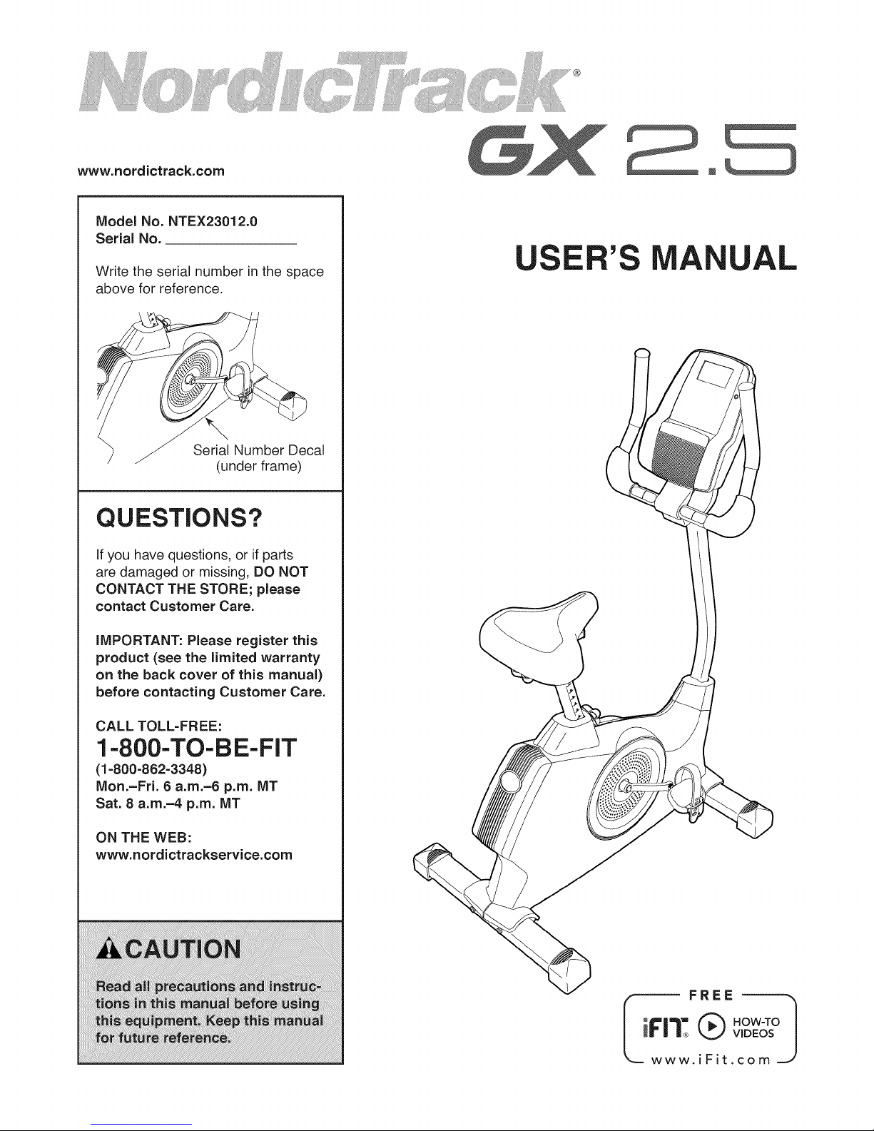
Model No. NTEX23012.0
Serial No.
Write the serial number in the space
above for reference.
Serial Number Decal
(under frame)
QUESTIONS?
if you have questions, or if parts
are damaged or missing, DO NOT
CONTACT THE STORE; please
contact Customer Care.
;ER'S A UAL
iMPORTANT: Please register this
product (see the limited warranty
on the back cover of this manual)
before contacting Customer Care.
CALL TOLL-FREE:
1-800-TO-BE-FIT
(1-800-862-3348)
Mon.=Fri. 6 a.m.=6 p.m. MT
Sat. 8 a.m.-4 p.m. MT
ON THE WEB:
www.nordictrackservice.com
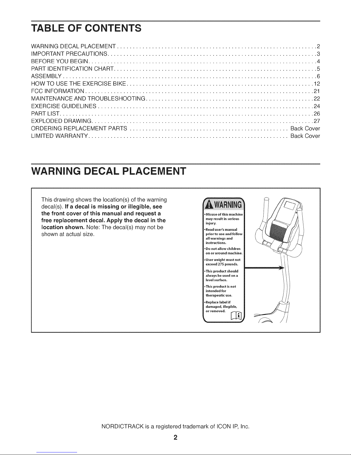
TABLE OF CONTENTS
WARNING DECAL PLACEMENT ............................................................... 2
IMPORTANT PRECAUTIONS .................................................................. 3
BEFORE YOU BEGIN ........................................................................ 4
PART IDENTIFICATION CHART ................................................................ 5
ASSEMBLY ................................................................................ 6
HOW TO USE THE EXERCISE BIKE ........................................................... 12
FCC INFORMATION ........................................................................ 21
MAINTENANCE AND TROUBLESHOOTING ..................................................... 22
EXERCISE GUIDELINES .................................................................... 24
PART LIST ................................................................................ 26
EXPLODED DRAWING ...................................................................... 27
ORDERING REPLACEMENT PARTS .................................................. Back Cover
LIMITED WARRANTY ............................................................... Back Cover
WARNING DECAL PLACEMENT
This drawing shows the location(s) of the warning
decal(s), if a decal is missing or illegible, see
the front cover of this manual and request a
free replacement decal. Apply the decal in the
location shown. Note: The decal(s) may not be
shown at actual size.
Misuse of this machine
may result in serious
injury.
*Read user's manual
prior to use and follow
all warnings and
instructions.
*De not allow children
on or around machine.
*User weight must not
exceed 275 pounds.
*This product should
always be used on a
level surface.
.This product is not
intended for
therapeutic use.
*Replace label if
damaged, illegible,
or removed. [_
NORDICTRACK is a registered trademark of ICON IP, Inc.
2
iMPORTANT PRECAUTIONS
3
BEFORE YOU BEGIN
Thank you for selecting the revolutionary
NORDICTRACK <_'GX 2.5 exercise bike. Cycling is an
effective exercise for increasing cardiovascular fitness,
building endurance, and toning the body. The GX 2.5
exercise bike provides an impressive selection of fea-
tures designed to make your workouts at home more
effective and enjoyable.
For your benefit, read this manual carefully before
you use the exercise bike. If you have questions after
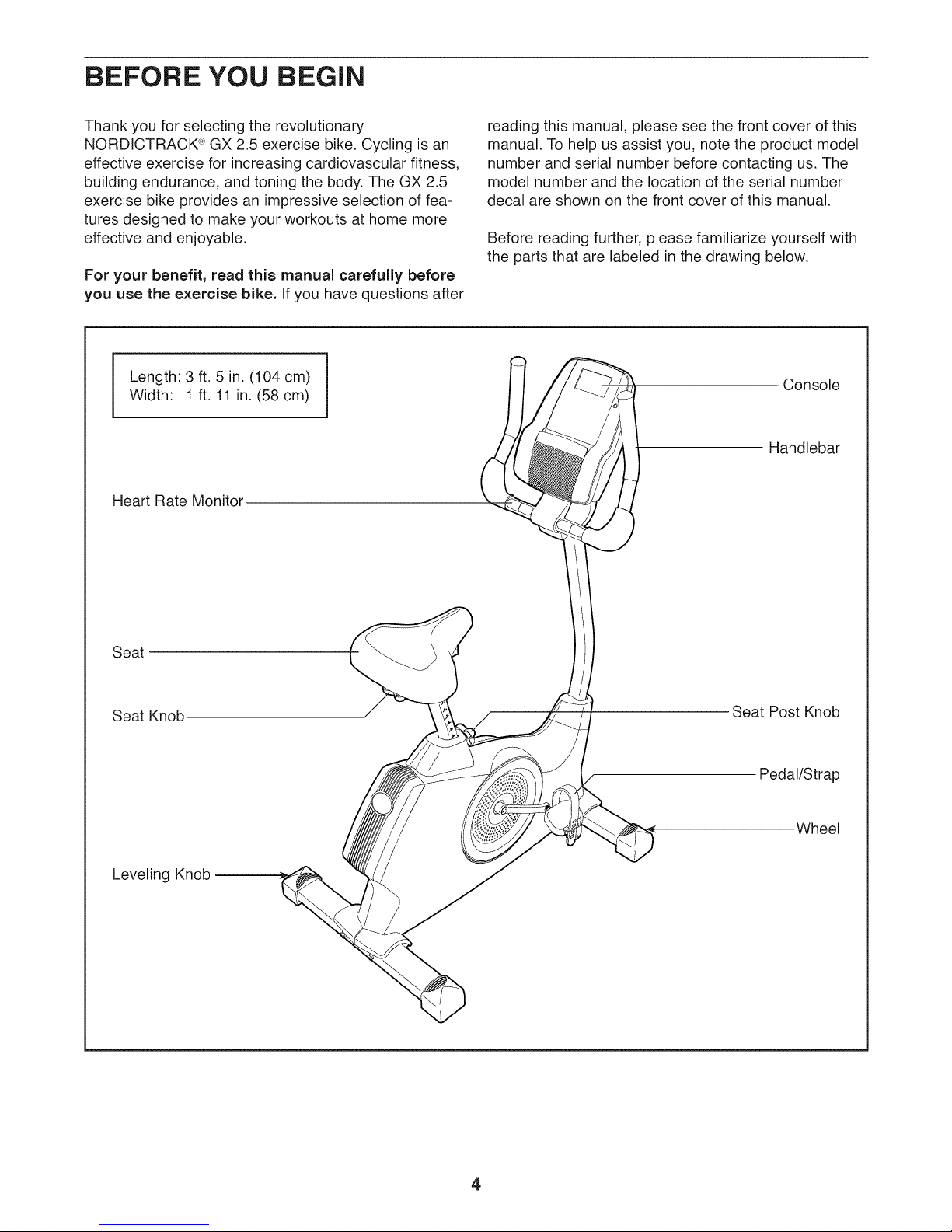
Length: 3 ft. 5 in. (104 cm)
Width: 1 ft. 11 in. (58 cm)
Heart Rate Monitor
reading this manual, please see the front cover of this
manual. To help us assist you, note the product model
number and serial number before contacting us. The
model number and the location of the serial number
decal are shown on the front cover of this manual.
Before reading further, please familiarize yourself with
the parts that are labeled in the drawing below.
Console
Handlebar
Seat
Seat Knob
Leveling Knob
Seat PostKnob
Pedal/Strap
Wheel
4
PART iDENTiFiCATiON CHART
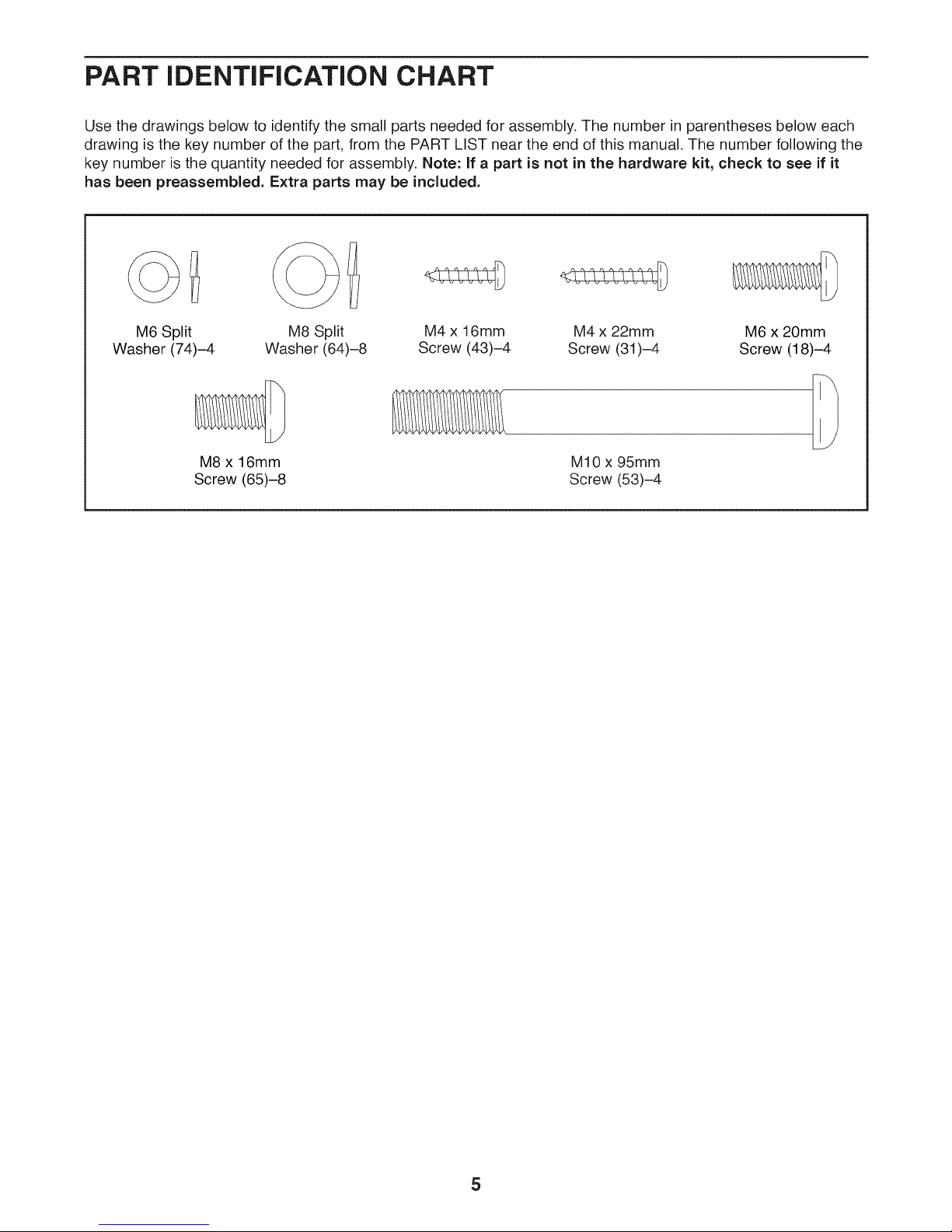
Use the drawings below to identify the small parts needed for assembly. The number in parentheses below each
drawing is the key number of the part, from the PART LIST near the end of this manual. The number following the
key number is the quantity needed for assembly. Note: If a part is not in the hardware kit, check to see if it
has been preassembled. Extra parts may be included.
M6 Split
Washer (74)-4
Screw (65)-8
Washer (64)-8 Screw (43)-4 Screw (31)-4
M8 x 16mm
M8 Split M4 x 16mm M4 x 22mm
M10 x 95mm
Screw (53)-4
M6 x 20mm
Screw (18)-4
5
ASSEMBLY
To watch an assembly
video, go to
http ://productvideo.co/
assembly/nordictrack or
use your mobile phone
or smartphone to read
the QR code at the right.
Assembly requires two
persons.
Place all parts in a cleared area and remove the
packing materials. Do not dispose of the packing
materials until you finish all assembly steps.
.
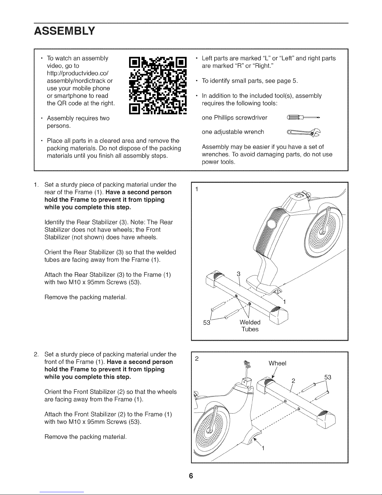
Set a sturdy piece of packing material under the
rear of the Frame (1). Have a second person
hold the Frame to prevent it from tipping
while you complete this step.
Identify the Rear Stabilizer (3). Note: The Rear
Stabilizer does not have wheels; the Front
Stabilizer (not shown) does have wheels.
Left parts are marked "L" or "Left" and right parts
are marked "R" or "Right."
To identify small parts, see page 5.
In addition to the included tool(s), assembly
requires the following tools:
one Phillips screwdriver (]_A::3=_
one adjustable wrench
Assembly may be easier if you have a set of
wrenches. To avoid damaging parts, do not use
power tools.
Orient the Rear Stabilizer (3) so that the welded
tubes are facing away from the Frame (1).
Attach the Rear Stabilizer (3) to the Frame (1)
with two M10 x 95mm Screws (53).
Remove the packing material.
.
Set a sturdy piece of packing material under the
front of the Frame (1). Have a second person
hold the Frame to prevent it from tipping
while you complete this step.
Orient the Front Stabilizer (2) so that the wheels
are facing away from the Frame (1).
Attach the Front Stabilizer (2) to the Frame (1)
with two M10 x 95mm Screws (53).
3
53 Welded
Tubes
Wheel
Remove the packing material.
6
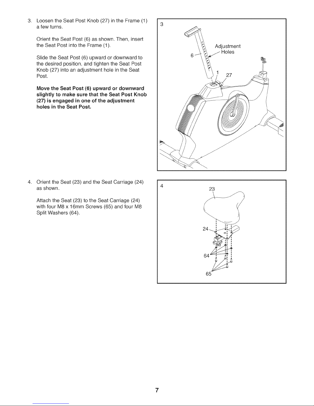
Loosen the Seat Post Knob (27) in the Frame (1)
3. 3
a few turns.
Orient the Seat Post (6) as shown. Then, insert
the Seat Post into the Frame (1).
Slide the Seat Post (6) upward or downward to
the desired position, and tighten the Seat Post
Knob (27) into an adjustment hole in the Seat
Post.
Move the Seat Post (6) upward or downward
slightly to make sure that the Seat Post Knob
(27) is engaged in one of the adjustment
holes in the Seat Post.
Adjustment
,
Orient the Seat (23) and the Seat Carriage (24)
as shown.
Attach the Seat (23) to the Seat Carriage (24)
with four M8 x 16mm Screws (65) and four M8
Split Washers (64).
4
23
i Ii
24_
9
65
7
.
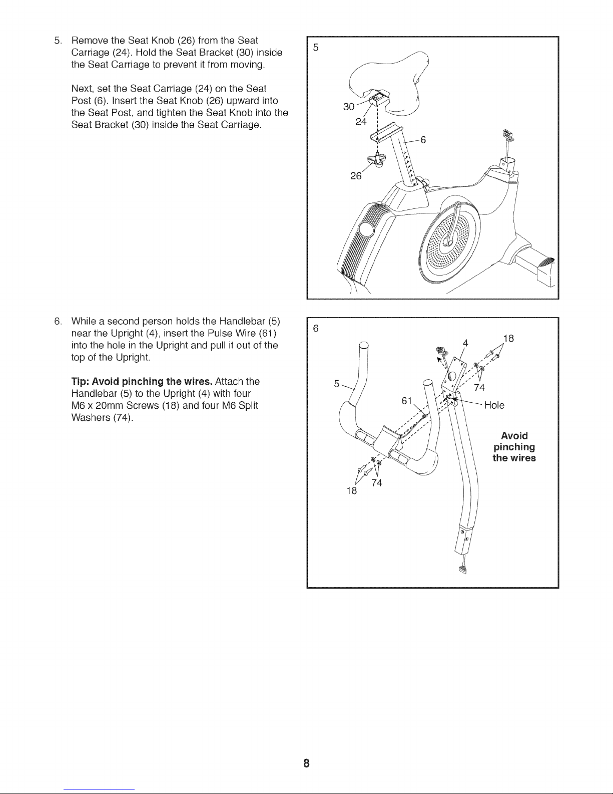
Remove the Seat Knob (26) from the Seat
Carriage (24). Hold the Seat Bracket (30) inside
the Seat Carriage to prevent it from moving.
Next, set the Seat Carriage (24) on the Seat
Post (6). Insert the Seat Knob (26) upward into
the Seat Post, and tighten the Seat Knob into the
Seat Bracket (30) inside the Seat Carriage.
.
While a second person holds the Handlebar (5)
near the Upright (4), insert the Pulse Wire (61)
into the hole in the Upright and pull it out of the
top of the Upright.
5
24
26
4
18
Tip: Avoid pinching the wires. Attach the
Handlebar (5) to the Upright (4) with four
M6 x 20mm Screws (18) and four M6 Split
Washers (74).
18
74
61
74
Hole
Avoid
pinching
the wires
8
.
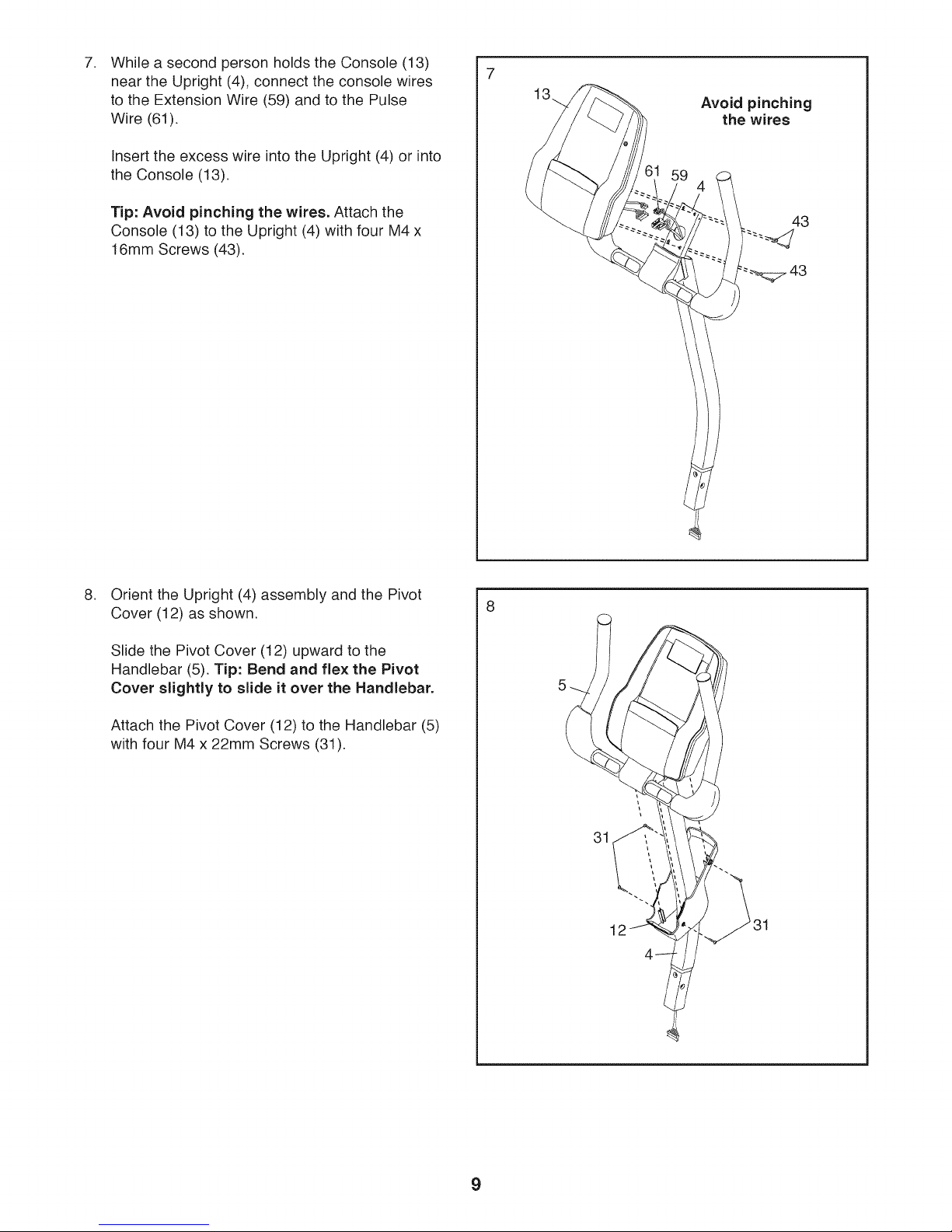
While a second person holds the Console (13)
near the Upright (4), connect the console wires
to the Extension Wire (59) and to the Pulse
Wire (61).
Insert the excess wire into the Upright (4) or into
the Console (13).
7
13
Avoid pinching
the wires
Tip: Avoid pinching the wires. Attach the
Console (13) to the Upright (4) with four M4 x
16mm Screws (43).
.
Orient the Upright (4) assembly and the Pivot
Cover (12) as shown.
Slide the Pivot Cover (12) upward to the
Handlebar (5). Tip: Bend and flex the Pivot
Cover slightly to slide it over the Handlebar.
43
---_._ 43
8
Attach the Pivot Cover (12) to the Handlebar (5)
with four M4 x 22mm Screws (31).
31
9
 Loading...