


CAUTION
Read all precautions and instructions in this manual before using
this equipment. Save this manual
for future reference.
Model No. NTSY59210
Serial No.
Write the serial number in the
space above for future reference.
Serial Number Decal (Under Seat)
QUESTIONS?
As a manufacturer, we are committed to providing complete
customer satisfaction. If you
have questions, or if there are
missing or damaged parts, we
will guarantee complete satisfaction through direct assistance from our factory.
TO AVOID DELAYS, PLEASE
CALL DIRECT TO OUR TOLLFREE CUSTOMER HOT LINE.
The trained technicians on our
customer hot line will provide
immediate assistance, free of
charge.
CUSTOMER HOT LINE:
1-888-825-2588
Mon.–Fri., 6 a.m.–6 p.m. MST
USER’S MANUAL
Visit our website at
www.nordictrack.com
new products, prizes,
fitness tips, and much more!

2
IMPORTANT PRECAUTIONS . . . . . . . . . . . . . . . . . . . . . . . . . . . . . . . . . . . . . . . . . . . . . . . . . . . . . . . . . . . . . 3
BEFORE YOU BEGIN . . . . . . . . . . . . . . . . . . . . . . . . . . . . . . . . . . . . . . . . . . . . . . . . . . . . . . . . . . . . . . . . . . . 4
ASSEMBLY . . . . . . . . . . . . . . . . . . . . . . . . . . . . . . . . . . . . . . . . . . . . . . . . . . . . . . . . . . . . . . . . . . . . . . . . . . . 5
ADJUSTMENTS . . . . . . . . . . . . . . . . . . . . . . . . . . . . . . . . . . . . . . . . . . . . . . . . . . . . . . . . . . . . . . . . . . . . . . 22
WEIGHT RESISTANCE CHART . . . . . . . . . . . . . . . . . . . . . . . . . . . . . . . . . . . . . . . . . . . . . . . . . . . . . . . . . . .24
TROUBLESHOOTING AND MAINTENANCE . . . . . . . . . . . . . . . . . . . . . . . . . . . . . . . . . . . . . . . . . . . . . . . . .25
CABLE DIAGRAM . . . . . . . . . . . . . . . . . . . . . . . . . . . . . . . . . . . . . . . . . . . . . . . . . . . . . . . . . . . . . . . . . . . . .26
EXERCISE GUIDELINES . . . . . . . . . . . . . . . . . . . . . . . . . . . . . . . . . . . . . . . . . . . . . . . . . . . . . . . . . . . . . . . 28
ORDERING REPLACEMENT PARTS . . . . . . . . . . . . . . . . . . . . . . . . . . . . . . . . . . . . . . . . . . . . . . . .Back Cover
LIMITED WARRANTY . . . . . . . . . . . . . . . . . . . . . . . . . . . . . . . . . . . . . . . . . . . . . . . . . . . . . . . . . . . Back Cover
Note: APART IDENTIFICATION CHART and a PART LIST/EXPLODED DRAWING are attached in the center of
this manual. Remove the PART IDENTIFICATION CHART and PART LIST/EXPLODED DRAWING before beginning assembly.
NordicTrack is a registered trademark of ICON Health & Fitness, Inc.
TABLE OF CONTENTS
1. Read all instructions in this manual before
using the weight system. Use the weight system only as described in this manual.
2. It is the responsibility of the owner to ensure
that all users of the weight system are adequately informed of all precautions.
3. The weight system is intended for home use
only. Do not use the weight system in any
commercial, rental, or institutional setting.
4. Use the weight system only on a level surface. Cover the floor beneath the weight system to protect the floor.
5. Make sure all parts are properly tightened
each time you use the weight system.
Replace any worn parts immediately.
6. Keep children under 12 and pets away from
the weight system at all times.
7. Keep hands and feet away from moving parts.
8. Always wear athletic shoes for foot protection while exercising.
9. Make sure that the cables remain on the pulleys at all times. If the cables bind as you are
exercising, stop immediately and make sure
that the cables are on the pulleys.
10. Never release the press arm, butterfly arm,
leg lever, lat bar, or ab strap while the
weights are raised; the weights will fall with
great force.
11. The weight system is designed to support a
maximum user weight of 300 pounds.
12. Make sure the weight pin is fully inserted
into the weight stack before you exercise.
13. Always disconnect the lat bar from the
weight system when performing an exercise
that does not use the lat bar.
14. If you feel pain or dizziness at any time while
exercising, stop immediately and begin cooling down.
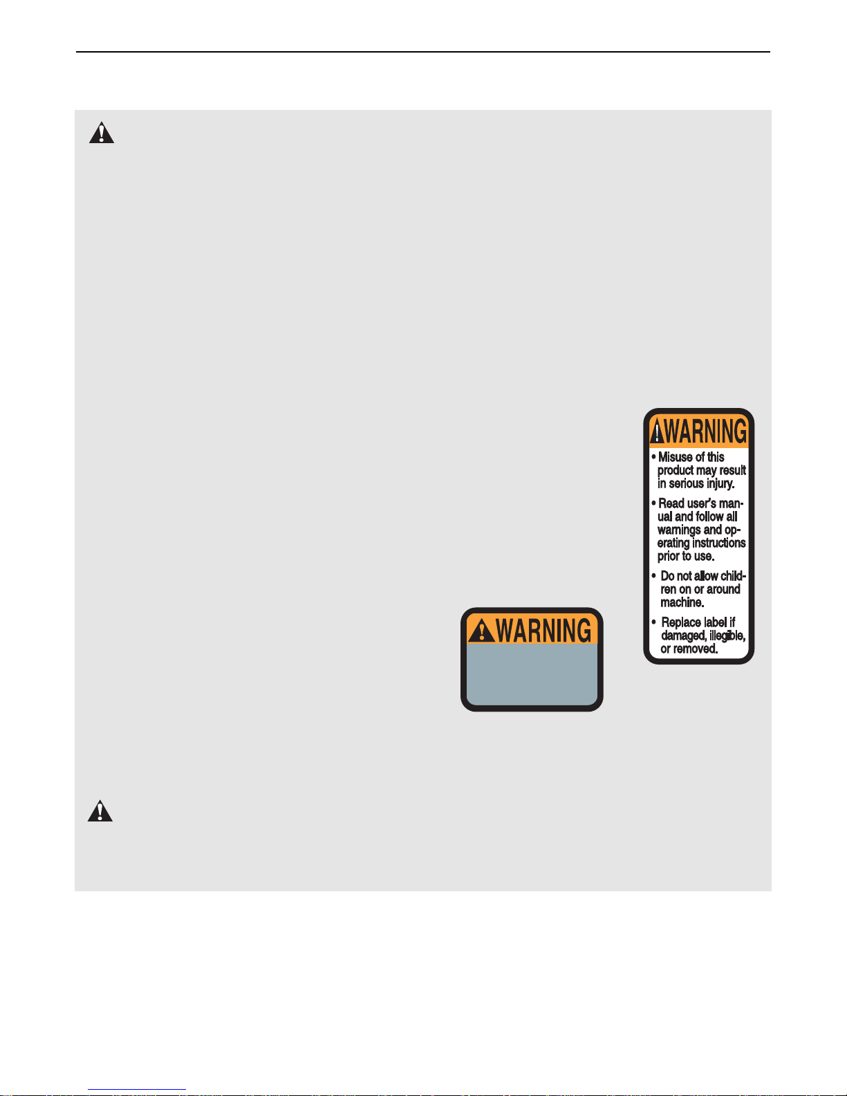
15. The decals shown below
have been placed on the
weight system in the
locations shown on page
4. If a decal is missing or
illegible, call our toll-free
Customer Hot Line at
1-888-825-2588 and order
a free replacement decal.
Apply the decal in the
location shown.
WARNING:
Before beginning this or any exercise program, consult your physician. This
is especially important for persons over the age of 35 or persons with pre-existing health problems.
Read all instructions before using. ICON assumes no responsibility for personal injury or property
damage sustained by or through the use of this product.
WARNING: To reduce the risk of serious injury, read the following important precautions
before using the weight system.
IMPORTANT PRECAUTIONS
3
Keep hands and
fingers clear of
this area
Decal 1
Decal 2
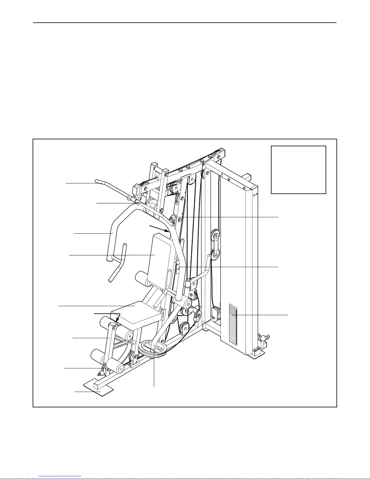
4
Weight Stack
Press Arm
Backrest Bracket
Foot Plate
Butterfly Arm
Right Side
Decal 2
Decal 1
(on the
upright)
Left Side
Note: The terms “right side” and “left side”
are determined relative to a person sitting
on the seat; they do not correspond to right
and left on the drawings in the manual.
Backrest
Low Pulley
Station
Ab Pulley Station
Press Arm Bracket
Leg Lever
Seat
Lat Bar
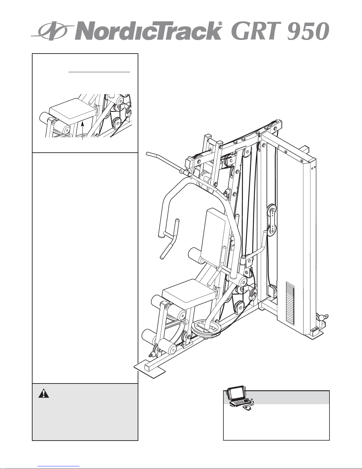
BEFORE YOU BEGIN
Thank you for selecting the versatile NordicTrack®GRT
950 weight system. The GRT 950 offers a selection of
weight stations designed to develop every major muscle group of the body. Whether your goal is to tone
your body, build dramatic muscle size and strength, or
improve your cardiovascular system, the GRT 950 will
help you to achieve the specific results you want.
For your benefit, read this manual carefully before
using the weight system. If you have additional
questions, please call our Customer Service
Department toll-free at 1-888-825-2588, Monday
through Friday, 6 a.m. until 6 p.m. Mountain Time
(excluding holidays). To help us assist you, please note
the product model number and serial number before
calling. The model number is NTSY59210. The serial
number can be found on a decal attached to the
weight system (see the front cover of this manual).
Before reading further, please review the drawing
below and familiarize yourself with the parts that are
labeled.
ASSEMBLED
DIMENSIONS:
Height: 84 in.
Width: 47 in.
Length: 68 in.
5
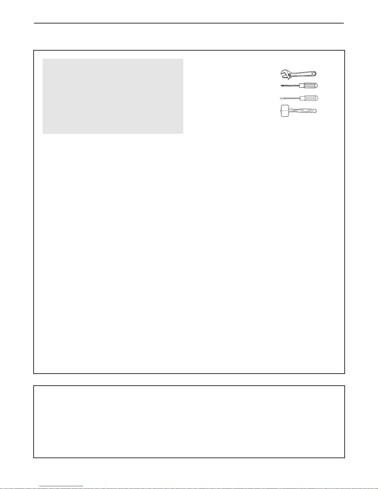
Make sure you have the following tools:
• Two adjustable wrenches
• One standard screwdriver
• One phillips screwdriver
• One rubber mallet
•You will also need grease or petroleum jelly, a
small amount of soapy water, and clear tape or
masking tape.
Note: Assembly will be more convenient if you have
a socket set, a set of open-end or closed-end
wrenches, or a set of ratchet wrenches.
How to Identify Parts
To help you identify the small parts used in assembly,
we have included a PART IDENTIFICATION CHART
in the center of this manual. Place the chart on the
floor and use it to easily identify parts during each
assembly step. Note: Some small parts may have
been pre-attached. If a part is not in the parts
bag, check to see if it has been pre-attached.
How to Orient Parts
As you assemble the weight system, make sure that
all parts are oriented exactly as shown in the drawings.
Tightening Parts
Tighten all parts as you assemble them, unless
instructed to do otherwise.
Questions?
If you have questions after reading the assembly
instructions, please call our Customer Service
Department at 1-888-825-2588.
Assembly Requires Two Persons
For your convenience and safety, assemble the
weight system with the help of another person.
Set Aside Enough Time
Due to the many features of the weight system, the
assembly process will take a few hours. By setting
aside plenty of time and by deciding to make the
task enjoyable, assembly will go smoothly. You may
want to assemble the weight system over a couple
of evenings.
Select a Location for the Weight System
Because of its weight and size, the weight system
should be assembled in the location where it will be
used. Make sure that there is enough room to walk
around the weight system as you assemble it.
How to Unpack the Box
To make assembly as easy as possible, we have
divided the assembly process into four stages. The
parts needed for each stage are found in individual
bags. Important: Wait until you begin each stage
to open the parts bag for that stage. Place all
parts of the weight system in a cleared area and
remove the packing materials. Do not dispose of
the packing materials until assembly is completed.
Make Assembly Easier for Yourself
Everything in this manual is designed to
ensure that the weight system can be assembled successfully by most people. Before
beginning assembly, make sure to read the
information on this page. This brief introduction will save you much more time than
it takes to read it.
The Four Stages of the Assembly Process
Frame Assembly—You will begin by assembling
the base and the uprights that form the skeleton of
the weight system.
Arm Assembly—During this stage you will
assemble the arms and the leg lever.
Cable Assembly—During this stage you will
attach the cables and pulleys that connect the
arms to the weights.
Seat Assembly—During the final stage you will
assemble the seats and the backrests.
ASSEMBLY
6
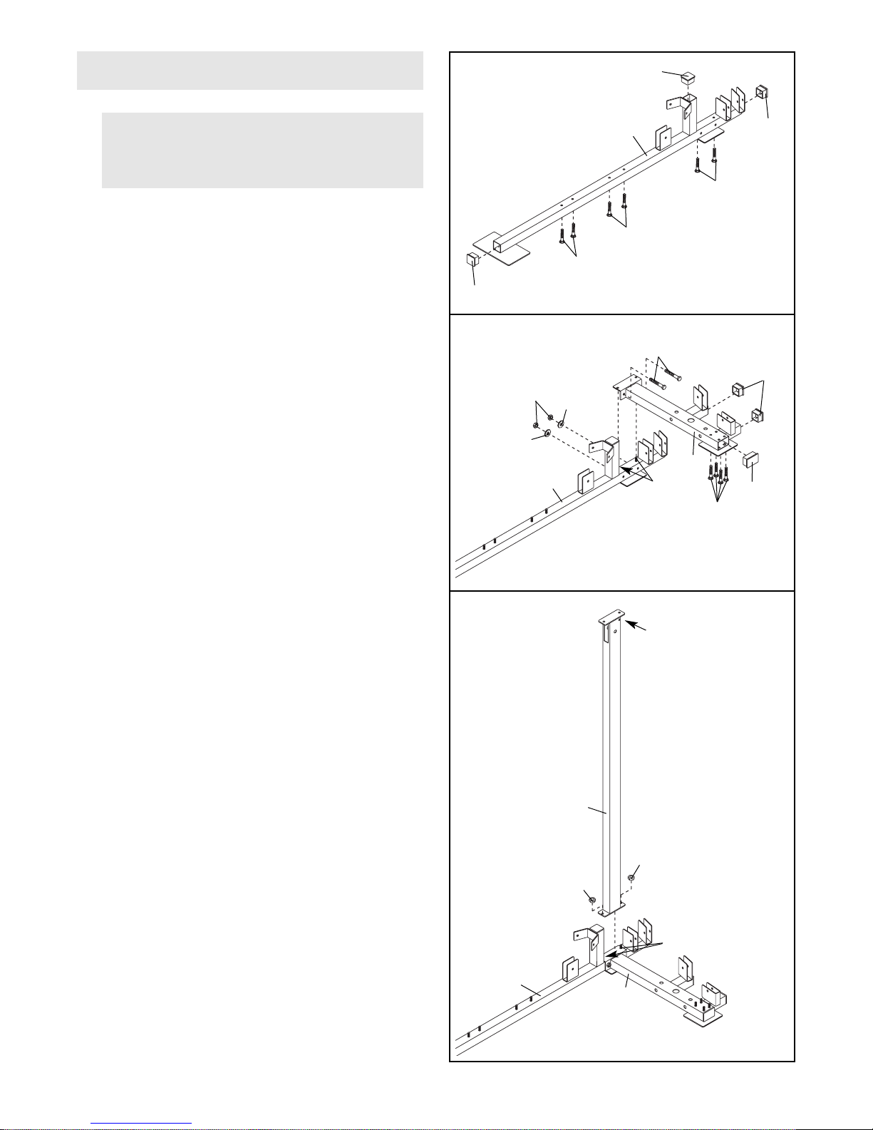
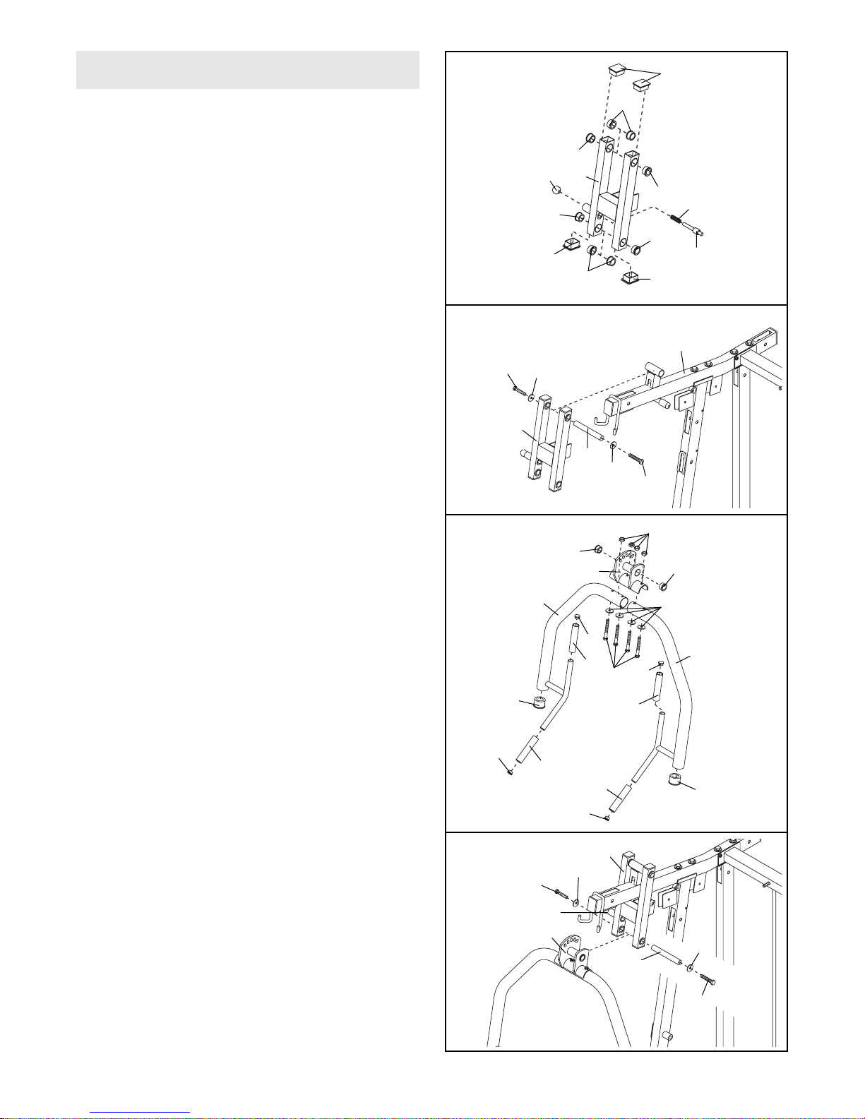
1.
Press three 50mm Square Inner Caps (72) into
the Press Base (1).
Insert four M10 x 67mm Carriage Bolts (87) and
two M10 x 72mm Carriage Bolts (73) up through
the bottom of the Press Base (1). Place the Press
Base flat on the floor. Note: If the Bolts fall out,
place a piece of tape over the bolt heads to
hold them in.
2. Press two 50mm Square Inner Caps (72) into the
extensions on the Rear Base (2). Press a 50mm x
75mm Inner Cap w/ Slot (95) into the end of the
Rear Base. Insert four M10 x 67mm Carriage Bolts
(87) up through the bottom of the Rear Base.
Slide the Rear Base (2) onto the two M10 x
72mm Carriage Bolts (73) in the Press Base (1).
Attach the Rear Base to the Press Base with two
M10 x 70mm Bolts (79), two M10 Washers (89),
and two M10 Nylon Locknuts (93). Do not tight-
en the Locknuts yet.
Note: If you have purchased the hack squat
extension (model NTSY3921), do not insert the
four M10 x 67mm Carriage Bolts (87) or the
50mm x 75mm Inner Cap w/ Slot (95) into the
Rear Base (2). Instead, complete step 2 in the
NTSY3921 manual.
Before beginning, read the information on
page 5. This brief introduction will save you
much more time than it takes to read it.
Frame Assembly
1
1
72
72
72
93
73
87
72
95
79
2
89
89
1
73
87
87
2
3. Attach the Right Upright (17) to the two M10 x
72mm Carriage Bolts (73) in the Press Base (1)
and Rear Base (2) with two M10 Nylon Locknuts
(93). Do not tighten the Locknuts yet. Make
sure the rod is on the indicated side of the
Upright.
3
17
Rod
93
73
2
1
93
7
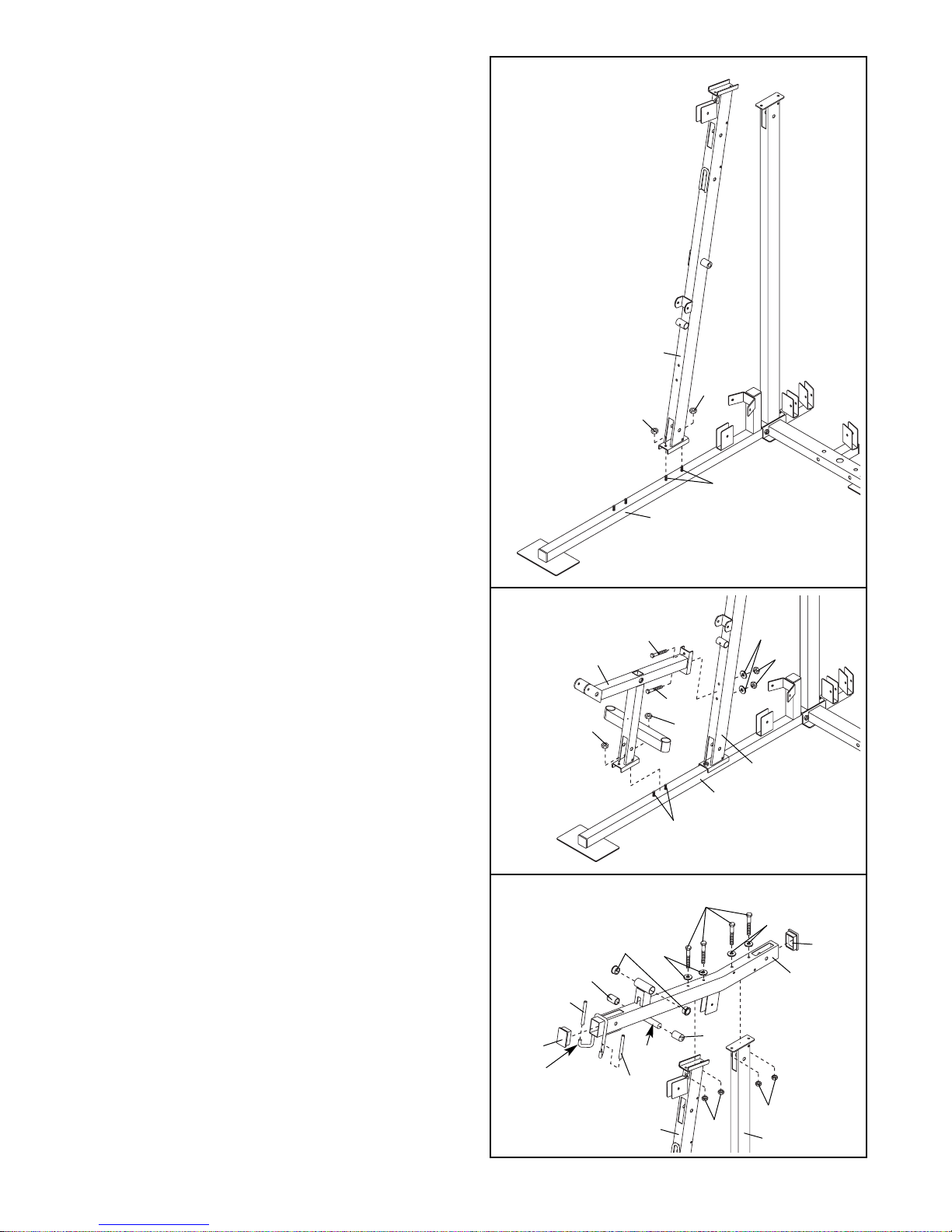
4. Attach the Press Upright (16) to the indicated two
M10 x 67mm Carriage Bolts (87) in the Press
Base (1) with two M10 Nylon Locknuts (93). Do
not tighten the Locknuts yet.
4
93
1
16
93
87
6. Press two Large Support Rod Bushings (66) into
the Press Top Frame (13). Press two 50mm x
75mm Inner Caps (68) into the ends of the Press
Top Frame. Press the two Rod Covers (41) onto
the indicated rod. Slide the two Barbell Hook
Sleeves (42) onto the barbell hooks.
Attach the Press Top Frame (13) to the Press
Upright (16) and the Right Upright (17) with four
M10 x 95mm Bolts (80), four M10 Washers (89),
and four M10 Nylon Locknuts (93). Do not tight-
en the Locknuts yet.
5. Attach the Seat Frame (3) to the indicated two
M10 x 67mm Carriage Bolts (87) in the Press
Base (1) with two M10 Nylon Locknuts (93).
Attach the Seat Frame (3) to the Press Upright
(16) with two M10 x 95mm Bolts (80), M10
Washers (89), and two M10 Nylon Locknuts (93).
Do not tighten the M10 Nylon Locknuts (93)
yet.
5
6
87
1
16
93
3
93
80
80
93
89
80
89
89
68
13
41
41
Rod
Barbell
Hook
42
42
68
93
93
17
16
66
8
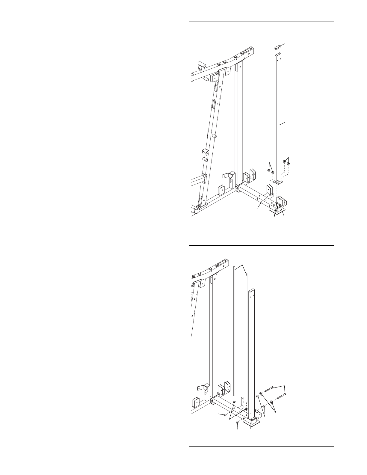
7. Press a 26mm x 76mm Inner Cap (74) into the
top of the Left Upright (20).
Attach the Left Upright (20) to the Rear Base (2)
with the four M10 x 67mm Bolts (87) and four
M10 Nylon Locknuts (93). Do not tighten the
Locknuts yet.
7
74
20
93
87
87
93
2
8. Press two Weight Guide Bushings (57) into the
Rear Base (2).
Set the two Weight Guides (27) in the indicated
holes in the Rear Base (2).
Slide two M8 x 90mm Bolts (90) through two M8
Large Washers (53), two 15mm x 30mm Spacers
(23), the Rear Base (2), the Weight Guides (27),
and two more 15mm x 30mm Spacers.
8
27
2
57
23
23
23
53
90
9
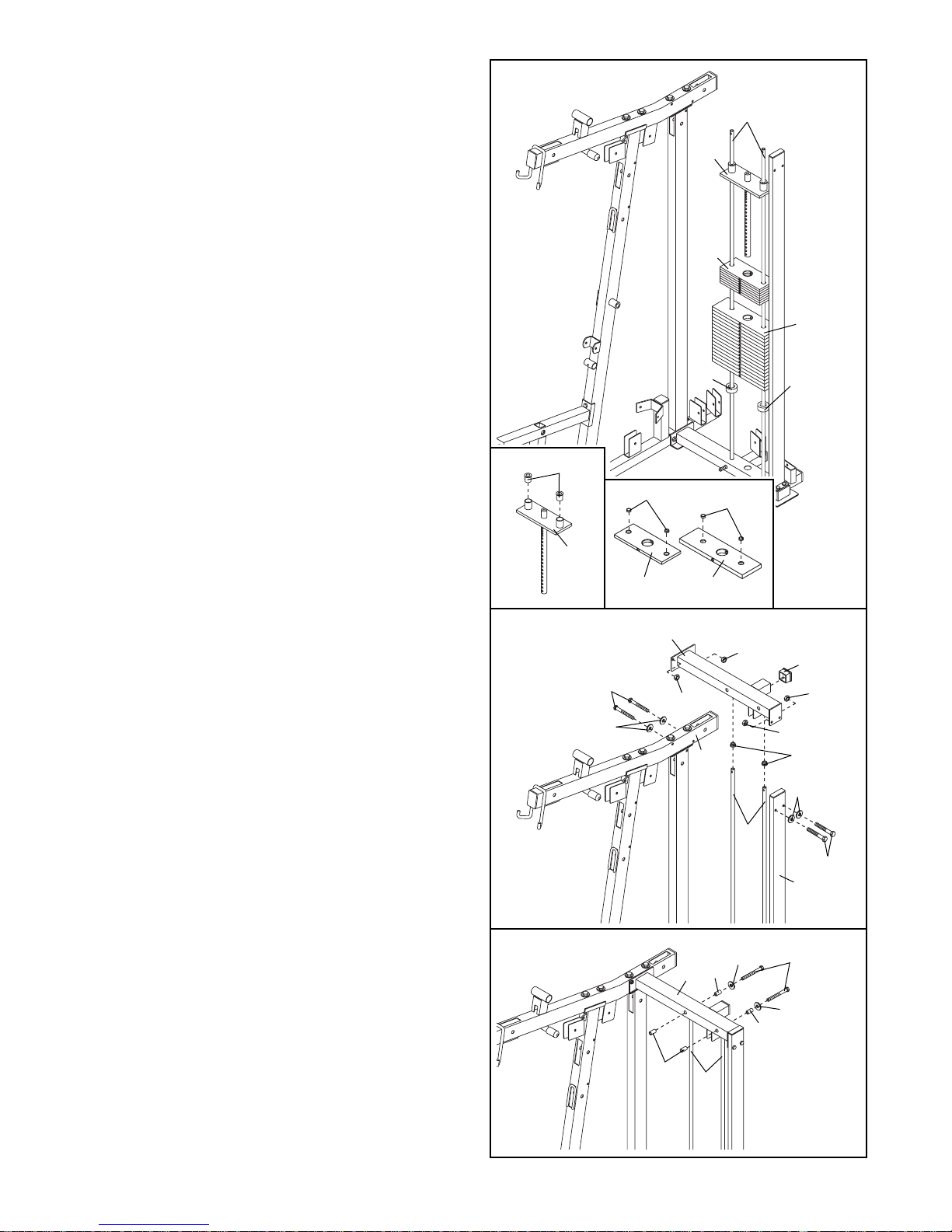
9. See the inset drawings. Press the two Top
Weight Bushings (33) into the Top Weight (32).
Press two 5-pound Weight Bushings (104) into
each 5-pound Weight (34). Press two 10-pound
Weight Bushings (61) into each 10-pound Weight
(29).
Slide a Weight Bumper (28) onto each Weight
Guide (27). Slide the sixteen 10-pound Weights
(29), the seven 5-pound Weights (34), and the
Top Weight (32) onto the Weights Guides in the
order shown.
9
27
32
34
29
28
32
61
34
29
104
33
28
10. Press a 50mm Square Inner Cap (72) into the
extension on the Rear Top Frame (19). Press two
Weight Guide Bushings (57) into the Rear Top
Frame.
Set the Rear Top Frame (19) onto the two Weight
Guides (27).
Attach the Rear Top Frame (19) to the Press Top
Frame (13) with two M10 x 70mm Bolts (79), two
M10 Washers (89), and two M10 Nylon Locknuts
(93).
Attach the Rear Top Frame (19) to the Left
Upright (20) with two M10 x 45mm Bolts (86), two
M10 Washers (89), and two M10 Nylon Locknuts
(93). Note: If you have purchased the hack
squat extension (model NTSY3921), do not
use the two M10 x 45mm Bolts (86) and two
M10 Washers (89). Instead, complete steps 3–8
in the NTSY3921 manual.
Do not tighten the M10 Nylon Locknuts (93)
yet.
11.Slide two M8 x 90mm Bolts (90) through two M8
Large Washers (53), two 15mm x 30mm Spacers
(23), the Rear Top Frame (19), the Weight Guides
(27), and two more 15mm x 30mm Spacers.
Tighten the M10 Nylon Locknuts (93) used in
steps 2–10.
10
11
79
93
93
93
57
89
86
13
27
20
19
93
72
89
27
90
23
23
53
53
23
19
10
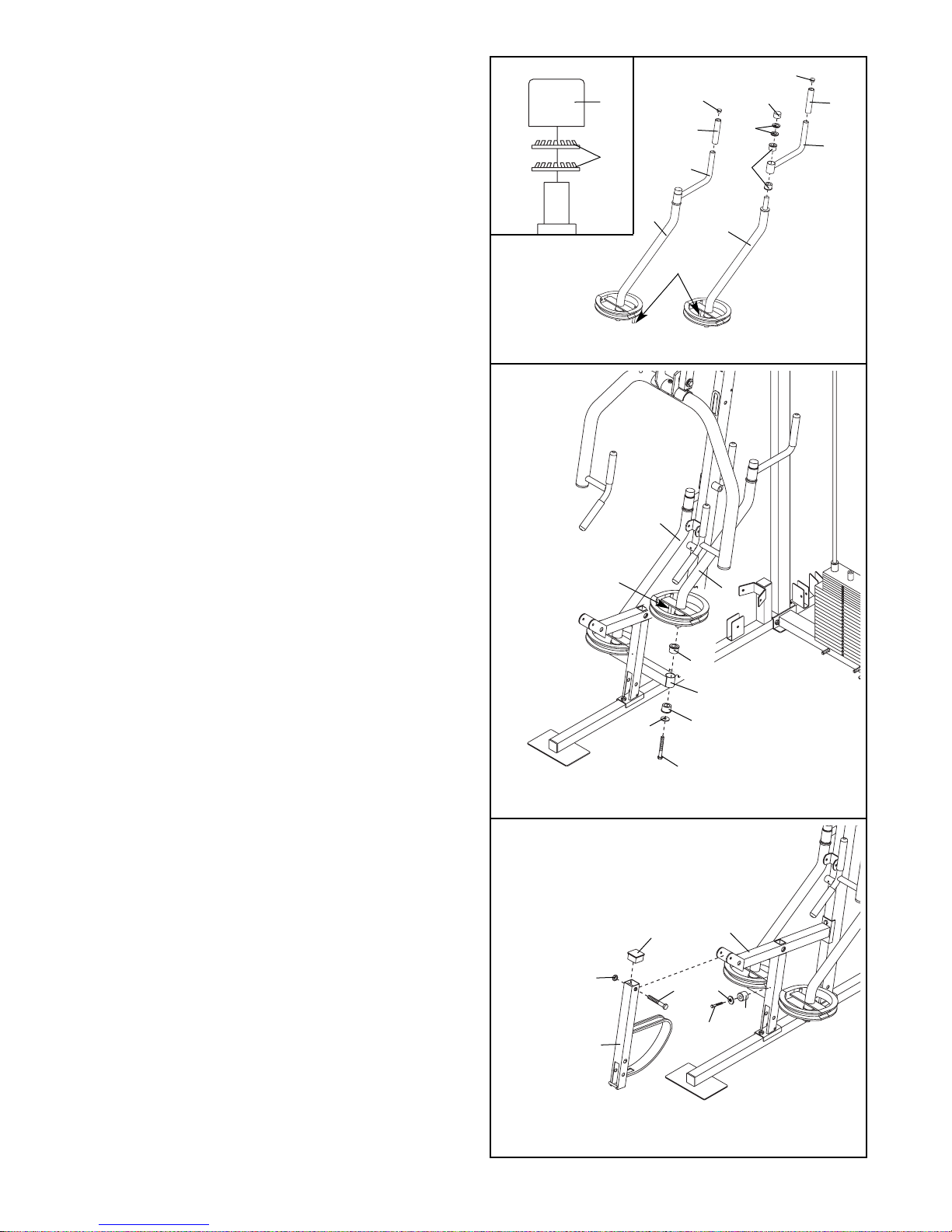
14. Press two 56mm Round Inner Caps (71) into the
ends of the Left and Right Arms (8, 9). Slide four
Long Handgrips (40) onto the Arms. Press four
31mm Round Inner Caps (50) into the Arms.
Press two Large Support Rod Bushings (66) into
the Press Bracket (10).
Orient the Left and Right Arms (8, 9) and the
Press Bracket (10) as shown. Attach the Arms to
the Press Bracket with four M10 x 75mm Bolts
(99), four M10 Washers (89), and four M10 Nylon
Locknuts (93).
13. Attach the Press Frame (12) to the Press Top
Frame (13) with a Long Support Rod (59), two
38mm Large Washers (81), and two M10 x 25mm
Bolts (82).
13
14
15. Pull the Knob w/ Threads (106) out as far as it will
go. Align a hole in the Press Bracket (10) with the
Knob, and engage the Knob into the hole.
Attach the Press Bracket (10) to the Press Frame
(12) with a Long Support Rod (59), two 38mm
Large Washers (81), and two M10 x 25mm Bolts
(82).
15
13
12
59
81
81
82
82
93
66
66
10
9
8
40
40
40
40
71
71
99
89
82
81
81
82
59
106
10
12
Arm Assembly
12. Press four 40mm x 50mm Inner Caps (67) into
the Press Frame (12). Press eight Large Support
Rod Bushings (66) into the Press Frame.
Attach the Ball w/Threads (106), the Spring (107),
and the 14mm Pin (56) to the Press Frame (12)
as shown.
12
67
67
67
66
66
12
66
66
66
106
107
56
66
50
50
50
50
11
17. Press two Butterfly Arm Bushings (64) into the
Seat Frame (3).
Attach the Left Butterfly Arm (6) to the Seat
Frame (3) with a 38mm Washer (81) and an M10
x 25mm Bolt (82). Make sure the rod on the
Butterfly Arm is behind the Seat Frame.
Repeat this step with the Right Butterfly Arm
(7).
16. Press two Large Handgrips (31) onto the two
Butterfly Handles (11). Press four Butterfly Arm
Bushings (64), and two 35mm Round Inner Caps
(39), into the Butterfly Handles.
Identify the Left and Right Butterfly Arms (6, 7) by
the location of the rods.
Slide a Handle (11) onto the Left Butterfly Arm
(6). Place two 1” Retainers (44) under a Round
Cover Cap (45), as shown in the inset drawing.
Be sure the teeth on the Retainers bend
toward the Cover Cap. Tap the Cover Cap and
Retainers onto the Left Butterfly Arm.
Attach the other Handle (11) to the Right
Butterfly Arm (7) in the same manner.
16
17
18. Press a 50mm Square Inner Cap (72) into the top
of the Leg Lever (4).
Attach a Bumper (51) to the Seat Frame (3) with
an M4 x 20mm Self-tapping Screw (65) and an
M4 Washer (24).
Lubricate an M10 x 75mm Bolt (99) with grease.
Attach the Leg Lever (4) to the Seat Frame (3)
with the Bolt and an M10 Nylon Locknut (93). Do
not overtighten the Locknut; the Leg Lever
must be able to pivot easily.
18
7
6
Rod
64
11
11
31
31
39
39
Rod
6
3
64
64
82
81
7
3
72
4
93
99
65
24
51
45
45
44
44
12
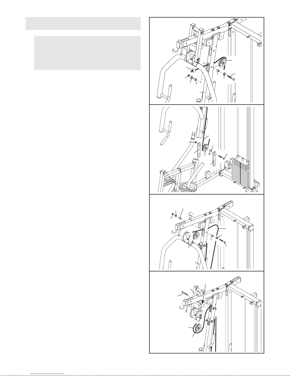
20. Wrap the Press Cable (101) around a 115mm
Pulley (54). Attach the Pulley and a Cable Trap
(52) to the top set of holes in a pair of Pulley
Plates (35) with an M10 x 50mm Bolt (77) and an
M10 Nylon Locknut (93). Be sure the Cable Trap
is turned to hold the Cable in the groove of
the Pulley.
21. Route the Press Cable (101) over a 115mm
Pulley (54) and through the Press Upright (16).
Attach the Pulley inside the Press Upright with an
M10 x 65mm Bolt (88), two M10 Washers (89),
two 15mm x 12mm Spacers (62), and an M10
Nylon Locknut (93).
19.
Locate the Press Cable (101). Route the eyelet
end of the Cable through the indicated hole in the
Press Upright (16).
Wrap the Press Cable (101) around a 115mm
Pulley (54). Attach the Pulley inside the Press
Upright (16) with an M10 x 65mm Bolt (88), two
M10 Washers (89), two 15mm x 12mm Spacers
(62), and an M10 Nylon Locknut (93).
19
20
21
Cable Assembly
IMPORTANT: Refer to the Cable Identification
Chart on page 26 for help identifying the
cables. Do not overtighten the bolts and
nuts attaching the pulleys; the pulleys must
be able to turn freely.
22. Wrap the Press Cable (101) around a 115mm
Pulley (54). Attach the Pulley to the bracket on
the Press Frame (12) with an M10 x 70mm Bolt
(79). Make sure the Bolt is inserted from the
indicated side. Do not thread a locknut onto
the Bolt yet.
22
62
54
101
93
16
89
89
88
62
54
35
35
77
93
52
101
62
88
89
89
54
62
93
16
54
101
Bracket
12
79
101