

NordicTrack 831283560 Owner’s Manual
Model No. NEL09940
'ial Number
Decal
QUESTIONS?
If you have questions, or if there
are missing parts, we will guar-
antee complete satisfaction
through direct assistance from
our factory.
ck
990
USER'S MANUAL
TO AVOID DELAYS, PLEASE
CALL DIRECT TO OUR TOLL-
FREE CUSTOMER HOT LINE.
The trained technicians on our
customer hot line will provide
immediate assistance, free of
charge to you.
CUSTOMER HOT LINE:
1-888-825-2588
Mon.-Fri., 6 a.m.-6 p.m. MST
Patent Pending
<iii!_iiiiiiiiiiiiiiiiiiiiiii¸_<iiiiiiiiiiiiiiiiiiiiiiiiiiiiiiiiiiiiiiiii¸¸ _<i!!_i<_
A CAUTIONiiiiii<i
!iiii!iii!_.... iiiiiiiiiiiiiiiiiii_iii!_iiii_! iiiiiiiiiiiiiiiiiiiii!ii!
www, nordictrack.com
new products, prizes,
fitness tips, and much more!
NordlcTrack
99O
TABLE OF CONTENTS
IMPORTANT PRECAUTIONS ............................................................. 3
BEFORE YOU BEGIN ................................................................... 4
ASSEMBLY ........................................................................... 5
HOW TO USE THE ELLIPTICAL EXERCISER ................................................ 10
MAINTENANCE AND TROUBLESHOOTING ................................................. 22
CONDITIONING GUIDELINES ............................................................ 23
PART LIST ........................................................................... 24
EXPLODED DRAWING ................................................................. 26
HOW TO ORDER REPLACEMENT PARTS ........................................... Back Cover
LIMITED WARRANTY ........................................................... Back Cover
NordicTrack is a registered trademark of ICON Health & Fitness, Inc.
2
IMPORTANT PRECAUTIONS
'_B= WARN ING: To reduce the risk of serious injury, read the following important precau-
tions before using the elliptical exerciser,
1. Read all instructions in this manual before
using the elliptical exerciser.
2. It is the responsibility of the owner to ensure
that all users of the elliptical exerciser are
adequately informed of all precautions,
3. The elliptical exerciser is intended for
in-home use only. Do not use the elliptical
exerciser in a commercial, rental, or institu-
tional setting.
4. Place the elliptical exerciser on a level sur-
face, with a mat beneath it to protect the
floor or carpet. Keep the elliptical exerciser
indoors, away from moisture and dust.
5. Inspect and properly tighten all parts regu-
larly, Replace any worn parts immediately.
6. Keep children under age 12 and pets away
from the elliptical exerciser at all times.
7. The elliptical exerciser should not be used
by persons weighing more than 250 pounds.
12. The pulse sensor is not a medical device.
Various factors, including the user's move-
ment, may affect the accuracy of heart rate
readings. The pulse sensor is intended only
as an exercise aid in determining heart rate
trends in general.
13. When you stop exercising, allow the pedals
to slowly come to a complete stop. The ellip-
tical exerciser does not have a free wheel;
the pedals will continue to move until the
flywheel stops.
14. Always unplug the power cord immediately
after use and before cleaning the elliptical
exerciser.
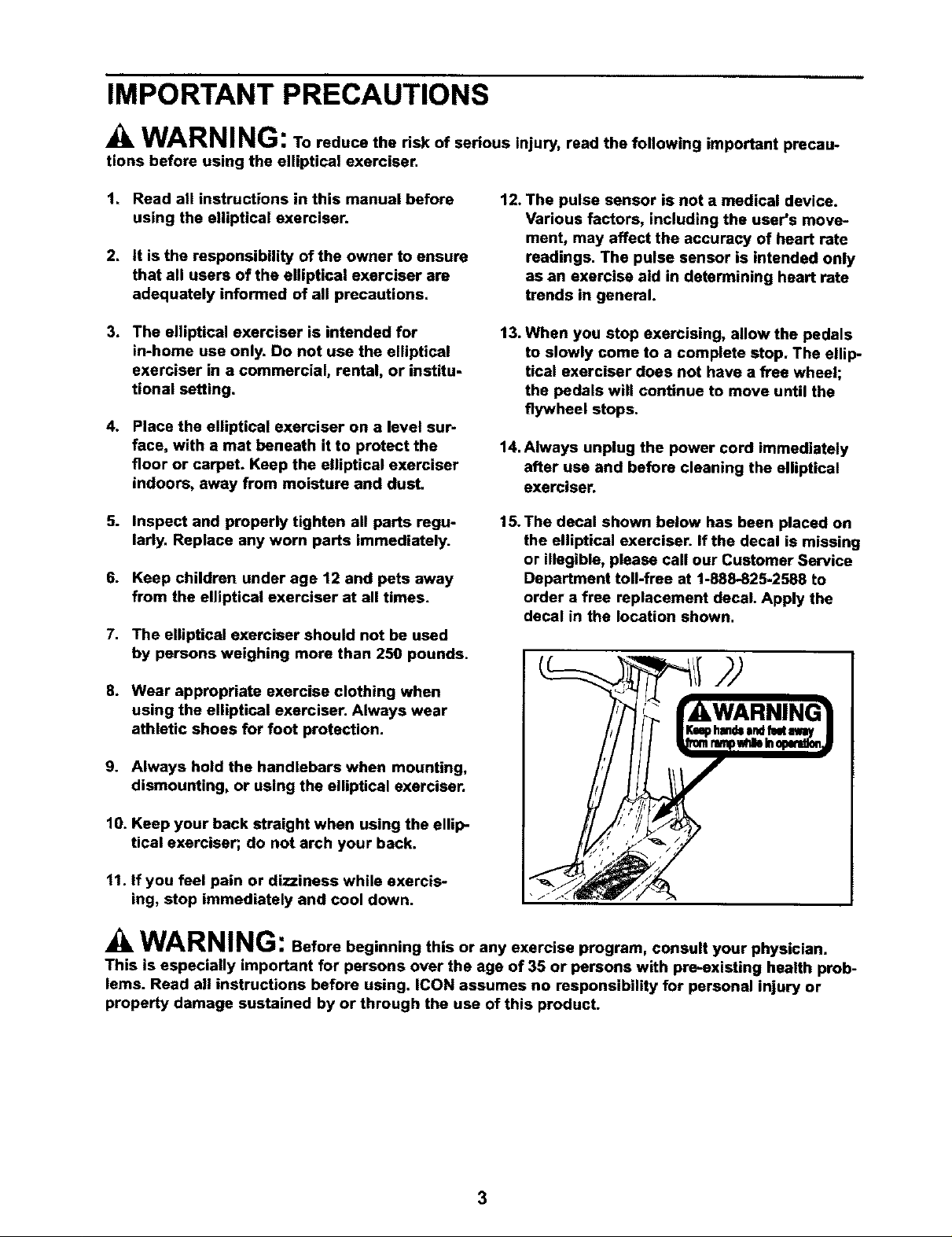
15. The decal shown below has been placed on
the elliptical exerciser. If the decal is missing
or illegible, please call our Customer Service
Department toll-free at 1-888-825-2588 to
order a free replacement decal. Apply the
decal in the location shown.
8. Wear appropriate exercise clothing when
using the elliptical exerciser. Always wear
athletic shoes for foot protection.
9. Always hold the handlebars when mounting,
dismounting, or using the elliptical exerciser.
10. Keep your back straight when using the ellip-
tical exerciser; do not arch your back.
11. If you feel pain or dizziness while exercis-
ing, stop immediately and cool down.
N(
WARNING: Before beginning this or any exercise program, consult your physician.
This is especially important for persons over the age of 35 or persons with pre-existing health prob-
lems. Read all instructions before using, ICON assumes no responsibility for personal injury or
property damage sustained by or through the use of this product.
3
BEFORE YOU BEGIN
Congratulations for selecting the new NordicTrack _
CX 990 elliptical exerciser. The CX 990 is an incredi-
bly smooth exerciser that moves your feet in a natural
elliptical path, minimizing the impact on your knees
and ankles. And the unique CX 990 features
adjustable resistance and incline to help you get the
most from your exercise. Welcome to a whole new
world of natural, elliptical-motion exercise from
NordicTrack.
For your benefit, read this manual carefully before
you use the elliptical exerciser. If you have ques-
Console
tions after reading the manual, please call our
Customer Service Department toll-free at 1-888-825-
2588, Monday through Friday, 6 a.m. until 6 p.m.
Mountain Time (excluding holidays). To help us assist
you, please note the product model number and serial
number before calling. The model number is
NEL09940. The sedal number can be found on a
decal attached to the elliptical exerciser (see the front
cover of this manual for the location of the decal).
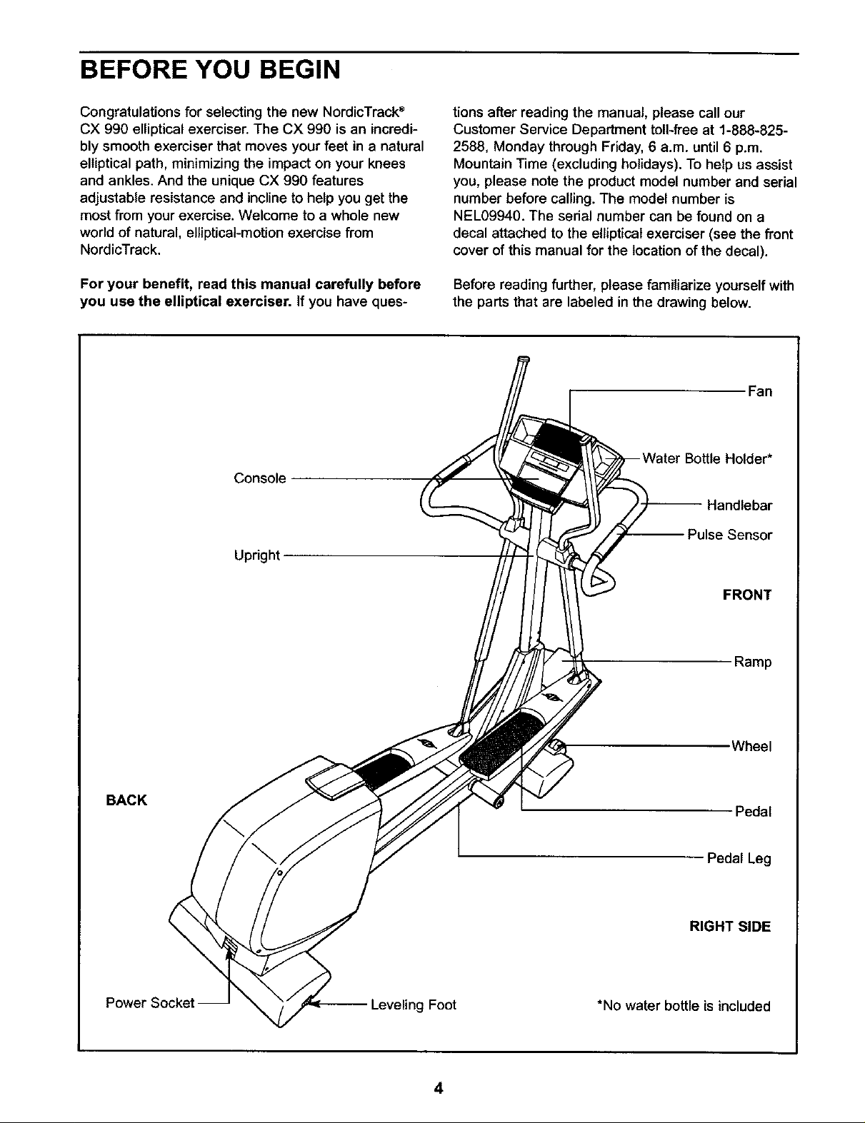
Before reading further, please familiarize yourself with
the parts that are labeled in the drawing below.
Fan
Holder*
Handlebar
BACK
-- Pulse Sensor
Upright
FRONT
Ramp
Wheel
Pedal
Pedal Leg
RIGHT SIDE
Power Socket
-- Leveling Foot
4
*No water bottle is included
ASSEMBLY
Assembly requires two people. Place all parts of the ellipticalexerciser in a cleared area and remove the
packing materials. Do not dispose of the packing materials until assembly is completed. In addition to the four
included allen wrenches, assembly requires a phillips screwdriver (_====_-, two adjustable
wrenches C_::_ , a rubber mallet _ , and pliers _.
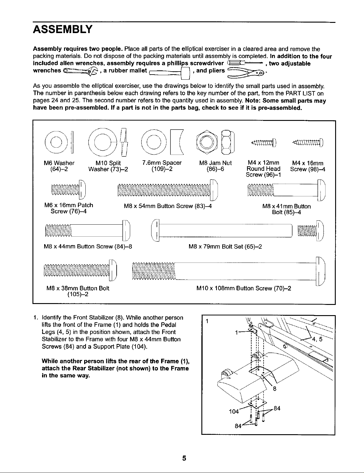
As you assemble the elliptical exerciser, use the drawings below to identify the small parts used in assembly.
The number in parenthesis below each drawing refers to the key number of the part, from the PART LIST on
pages 24 and 25. The second number refers to the quantity used in assembly. Note: Some small parts may
have been pre-assembled. If a part is not in the parts bag, check to see if it is pre-assembled.
M6 Washer M10 Split 7.6ram Spacer M8 Jam Nut
(64)-2 Washer (73)-2 (109)-2 (86)-6
M6 x 16mm Patch
Screw (76)-4
M8 x 38mm Button Bolt
(105)-2
1. Identify the Front Stabilizer (8). While another person
lifts the front of the Frame (1) and holds the Pedal
Legs (4, 5) in the position shown, attach the Front
Stabilizer to the Frame with four M8 x 44ram Button
Screws (84) and a Support Plate (104).
M8 x 54mm Button Screw (83)-4
M8 x 79mm Bolt Set (65)-2M8 x 44mm Button Screw (84)-8
M10 x 108mm Button Screw (70)-2
M4 x 12ram M4x 16mm
Round Head Screw (98)-4
Screw (96)-1
M8 x41mm Button
Bolt (85)-4
While another person lifts the rear of the Frame (1),
attach the Rear Stabilizer (not shown) to the Frame
in the same way.
5
8
,.84
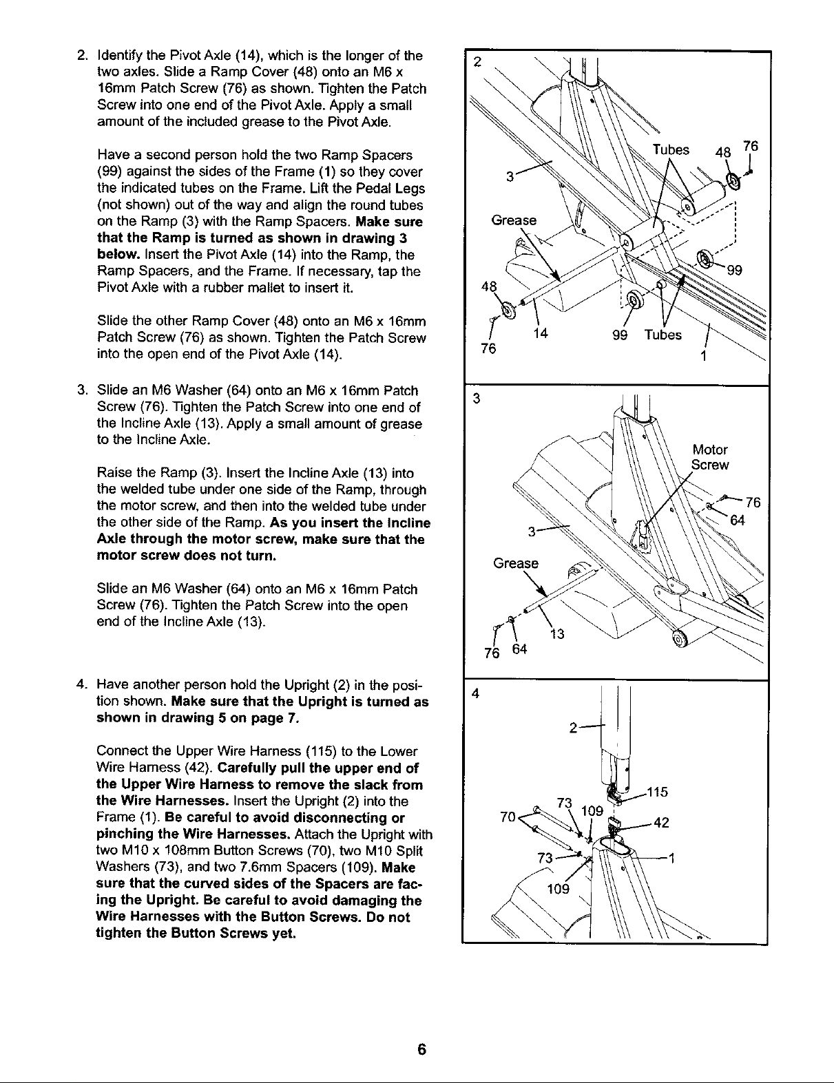
2. Identify the Pivot Axle (14), which is the longer of the
two axles. Slide a Ramp Cover (48) onto an M6 x
16mm Patch Screw (76) as shown. Tighten the Patch
Screw into one end of the Pivot Axle. Apply a small
amount of the included grease to the Pivot Axle.
2
Have a second person hold the two Ramp Spacers
(99) against the sides of the Frame (1) so they cover
the indicated tubes on the Frame. Lift the Pedal Legs
(not shown) out of the way and align the round tubes
on the Ramp (3) with the Ramp Spacers. Make sure
that the Ramp is turned as shown in drawing 3
below. Insert the Pivot Axle (14) into the Ramp, the
Ramp Spacers, and the Frame. If necessary, tap the
Pivot Axle with a rubber mallet to insert it.
Slide the other Ramp Cover (48) onto an M6 x 16ram
Patch Screw (76) as shown. Tighten the Patch Screw
into the open end of the Pivot Axle (14).
3. Slide an M6 Washer (64) onto an M6 x 16mm Patch
Screw (76). T_ghten the Patch Screw into one end of
the Incline Axle (13). Apply a small amount of grease
to the Incline Axle.
Raise the Ramp (3). Insert the Incline Axle (13) into
the welded tube under one side of the Ramp, through
the motor screw, and then into the welded tube under
the other side of the Ramp. As you insert the Incline
Axle through the motor screw, make sure that the
motor screw does not turn.
76
Grease
14
48
99 Tubes
Slide an M6 Washer (64) onto an M6 x 16mm Patch
Screw (76). Tighten the Patch Screw into the open
end of the Incline Axle (13).
4. Have another person hold the Upright (2) in the posi-
tion shown. Make sure that the Upright is turned as
shown in drawing 5 on page 7.
Connect the Upper Wire Harness (115) to the Lower
Wire Hamess (42). Carefully pull the upper end of
the Upper Wire Harness to remove the slack from
the Wire Harnesses. Insert the Upright (2) intothe
Frame (1). Be careful to avoid disconnecting or
pinching the Wire Harnesses, Attach the Upright with
two M10 x 108mm Button Screws (70), two M10 Split
Washers (73), and two 7.6mm Spacers (109). Make
sure that the curved sides of the Spacers are fac-
ing the Upright. Be careful to avoid damaging the
Wire Harnesses with the Button Screws. Do not
tighten the Button Screws yet,
13
64
4
70_
109
6
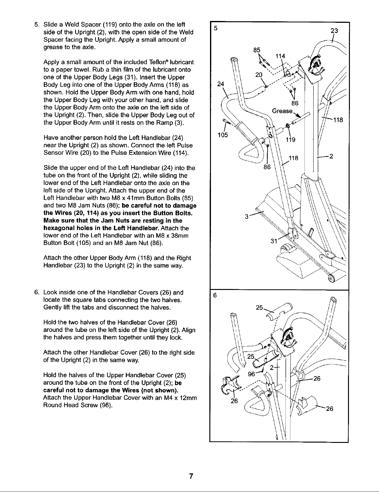
5. Slide a Weld Spacer (119) onto the axle on the left
side of the Upright (2), with the open side of the Weld
Spacer facing the Upright. Apply a small amount of
grease to the axle.
Apply a small amount of the included Teflon®lubricant
to a paper towel. Rub a thin film of the lubricant onto
one of the Upper Body Legs (31). Insert the Upper
Body Leg into one of the Upper Body Arms (118) as
shown. Hold the Upper Body Arm with one hand, hold
the Upper Body Leg with your other hand, and slide
the Upper Body Arm onto the axle on the left side of
the Upright (2). Then, slide the Upper Body Leg out of
the Upper Body Arm until it rests on the Ramp (3).
5
85
114
24
23
Have another person hold the Left Handlebar (24)
near the Upright (2) as shown. Connect the left Pulse
Sensor Wire (20) to the Pulse Extension Wire (114).
Slide the upper end of the Left Handlebar (24) into the
tube on the front of the Upright (2), while sliding the
lower end of the Left Handlebar onto the axle on the
left side of the Upright. Attach the upper end of the
Left Handlebar with two M8 x 41mm Button Bolts (85)
and two M8 Jam Nuts (86); be careful not to damage
the Wires (20, 114) as you insert the Button Bolts.
Make sure that the Jam Nuts are resting in the
hexagonal holes in the Left Handlebar. Attach the
lower end of the Left Handlebar with an M8 x 38ram
Button Bolt (105) and an M8 Jam Nut (86).
Attach the other Upper Body Arm (118) and the Right
Handlebar (23) to the Upright (2) in the same way.
6. Look inside one of the Handlebar Covers (26) and
locate the square tabs connecting the two halves.
Gently lift the tabs and disconnect the halves.
105
86
\
Hold the two halves of the Handlebar Cover (26)
around the tube on the left side of the Updght (2). Align
the halves and press them together until they lock.
Attach the other Handlebar Cover (26) to the right side
of the Upright (2) in the same way.
Hold the halves of the Upper Handlebar Cover (25)
around the tube on the front of the Upright (2); be
careful not to damage the Wires (not shown).
Attach the Upper Handlebar Cover with an M4 x 12mm
Round Head Screw (g6).
7
26
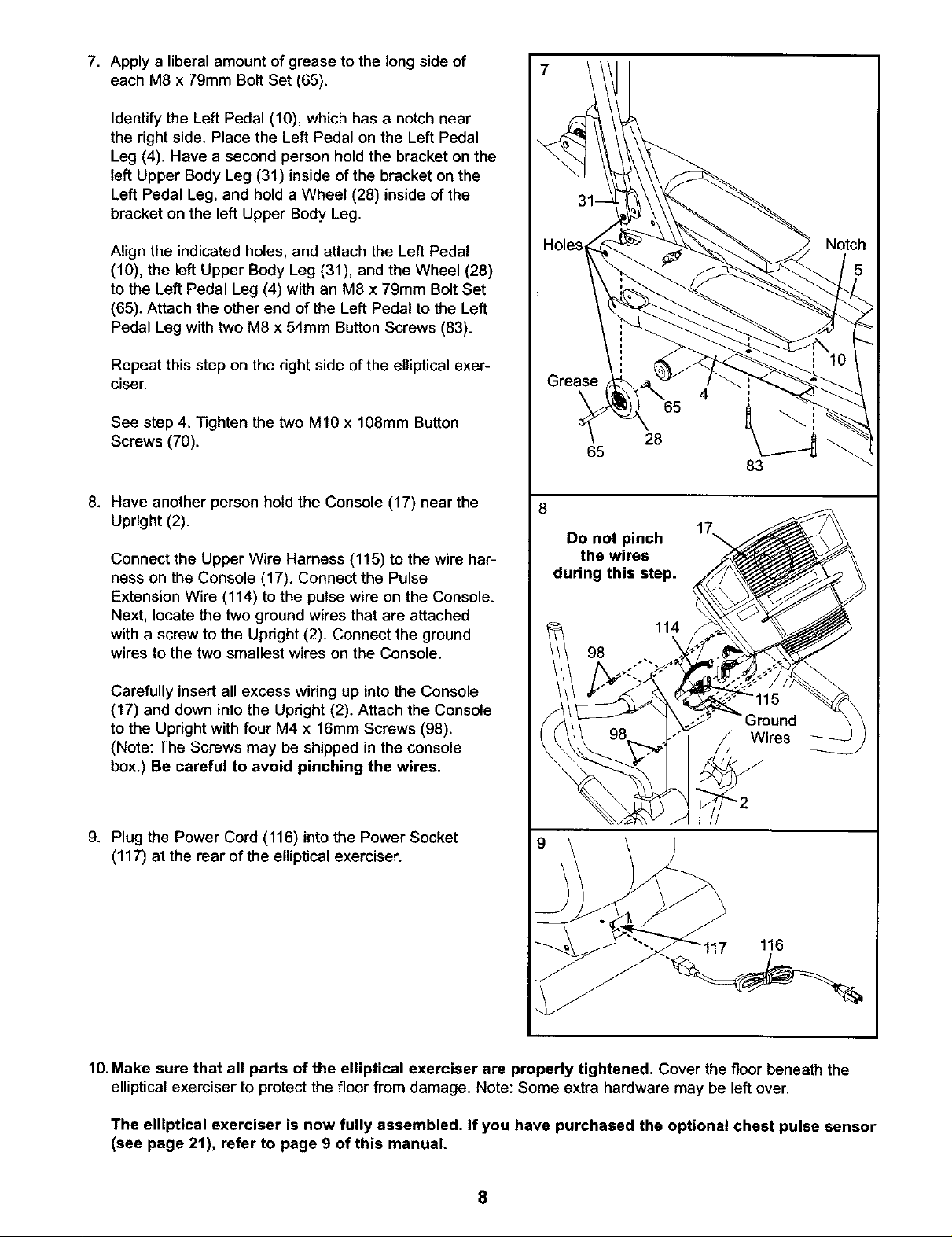
7. Apply a liberal amount of grease to the long side of
each M8 x 79mm Bolt Set (65).
Identify the Left Pedal (10), which has a notch near
the right side. Place the Left Pedal on the Left Pedal
Leg (4). Have a second person hold the bracket on the
left Upper Body Leg (31) inside of the bracket on the
Left Pedal Leg, and hold a Wheel (28) inside of the
bracket on the left Upper Body Leg.
Align the indicated holes, and attach the Left Pedal
(10), the left Upper Body Leg (31), and the Wheel (28)
to the Left Pedal Leg (4) with an M8 x 79mm Bolt Set
(65). Attach the other end of the Left Pedal to the Left
Pedal Leg with two M8 x 54mm Button Screws (83).
Repeat this step on the right side of the elliptical exer-
ciser.
See step 4. Tighten the two M10 x 108mm Button
Screws (70).
8. Have another person hold the Console (17) near the
Upright (2).
Connect the Upper Wire Harness (115) to the wire har-
ness on the Console (17). Connect the Pulse
Extension Wire (114) to the pulse wire on the Console.
Next, locate the two ground wires that are attached
with a screw to the Upright (2). Connect the ground
wires to the two smallest wires on the Console.
Carefully insert all excess wiring up into the Console
(17) and down into the Upright (2). Attach the Console
to the Upright with four M4 x 16mm Screws (98).
(Note: The Screws may be shipped in the console
box.) Be careful to avoid pinching the wires.
Notch
4
65
28
65
8
Do not pinch
the wires
during this step.
114
98
9. Plug the Power Cord (116) into the Power Socket
(117) at the rear of the elliptical exerciser.
116
10.Make sure that all parts of the elliptical exerciser are properly tightened. Cover the floor beneath the
elliptical exerciser to protect the floor from damage, Note: Some extra hardware may be left over.
The elliptical exerciser is now fully assembled. If you have purchased the optional chest pulse sensor
(see page 2t), refer to page 9 of this manual.
8
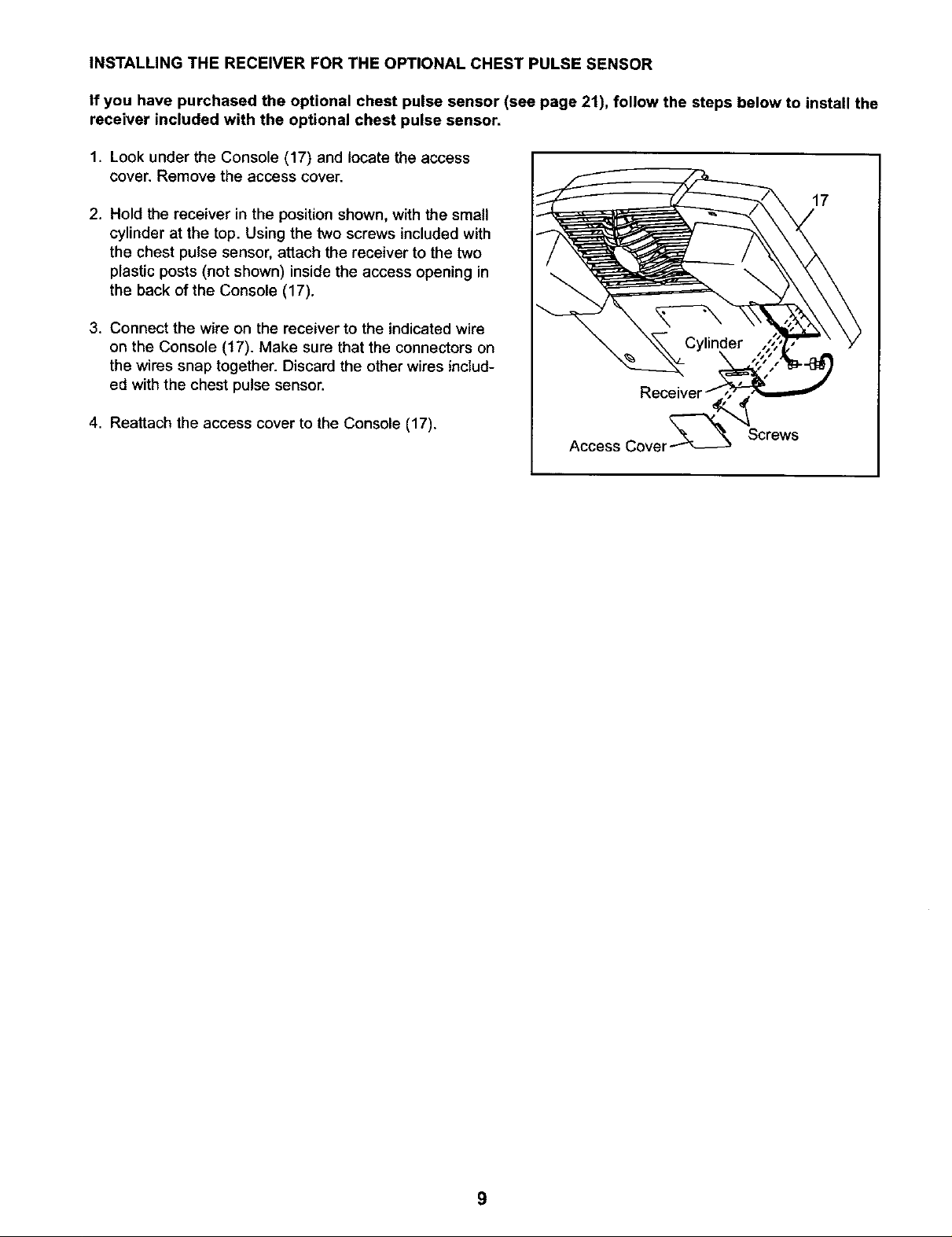
INSTALLING THE RECEIVER FOR THE OPTIONAL CHEST PULSE SENSOR
If you have purchased the optional chest pulse sensor (see page 21), follow the steps below to install the
receiver included with the optional chest pulse sensor.
1. Look under the Console (17) and locate the access
cover. Remove the access cover.
17
2. Hold the receiver in the position shown, with the small
cylinder at the top. Using the two screws included with
the chest pulse sensor, attach the receiver to the two
plastic posts (not shown) inside the access opening in
the back of the Console (17).
3. Connect the wire on the receiver to the indicated wire
on the Console (17). Make sure that the connectors on
the wires snap together. Discard the other wires includ-
ed with the chest pulse sensor.
4. Reattach the access cover to the Console (17).
Access Cover_
Screws
9
 Loading...