

NordicTrack 831283141 Owner’s Manual
Model No. NTC59021
Seriai No.
Serial
Number
Decal
QUESTIONS?
®
As a manufacturer, we are com-
mitted to providing complete
customer satisfaction, if you
have questions, or if there are
missing parts, we will guarantee
satisfaction through direct assis-
tance from our factory.
TO AVOID DELAYS, PLEASE
CALL DIRECT TO OUR TOLL-
FREE CUSTOMER HOT LINE.
The trained technicians on our
customer hot line witl provide
immediate assistance, free of
charge to you.
CUSTOMER HOT LINE:
1°888°825°2588
Mon.-Fti., 6 a.m.-6 p.m. MST
Patent Pending
_CAUTION
Read all precautions and instruc-
tions in this manua_ before using
this equipment. Keep this manual
for future reference.
t our website at_
www.nordictrack.com
new products, prizes,
fitness tips, and much more!
TABLE OF CONTENTS
NordicTrack is a registered trademark of ICON Health & Fitness, Inc.
iMPORTANT PRECAUTIONS
_'_WARNING: Toreducether,skofser,ous,njury,readthefo.ow,ng,mportant precau-
tionsbefore using the exercise cycle.
1. Read all instructions in this manual before 7. Wear suitable clothing when using the
using the exercise cycle, Use the exercise
cycle only as described,
2. it is the responsibility of the owner to
ensure that all users of the exercise cycle
are adequately informed of all precautions.
3. Use the exercise cycle indoors on a level
surface. Keep the exercise cycle away from
moisture and dust. Place a mat under the
exercise cycle to protect the floor or carpet.
,
inspect and proper_y tighten all parts regu- merit, may affect the accuracy of heart rate
laHy. Replace any worn parts immediately, readings. The pulse sensor is intended only
5. Keep children under the age of 12 and pets
away from the exercise cycle at aJ_times.
6. The exercise cycle should not be used by
persons weighing more t_an 250 pounds.
exercise cycle; do _ot wear loose clothing
that could become caught on the exercise
cycle. Always wear athletic shoes.
8. Always keep your back straight when using
the exercise cycle. Do not arch your back.
9. if you feel pain or dizziness while exercis-
ing, stop immediately and cool down.
10. The puJae sensor is not a medical device,
Various factors, including the user's move°
as an exercise aid in determining heart rate
trends in general
11. The exercise cycle is intended for in=home
use onJyo Do not use the exercise cycle in a
commercial rental, or institutional setting.
WAR NING: Beforebeginningth_soranyexerciseprogram,consultyourphysician.Th_s
is especially important for persons over the age of 35 or persons with pre-existing heaJth problems.
Read all instructions before using. ICON assumes no responsibility for personal injury or property
damage sustained by or through the use of this product.
2
BEFORE YOU BEGIN
Congratulations for selecting the new NordicTrack _
SL 700 exercise cycle. Cycling is one of the most
effective exercises for increasing cardiovascular fit-
ness, building endurance, and toning the entire body.
The NordicTrack _ SL 700 offers an impressive array
of features designed to let you enjoy this healthful
exercise in the comfort and privacy of your home.
For your benefit, read this manual carefully before
you use the exercise cycme. If you have questions
after reading this manual, call our Customer Service
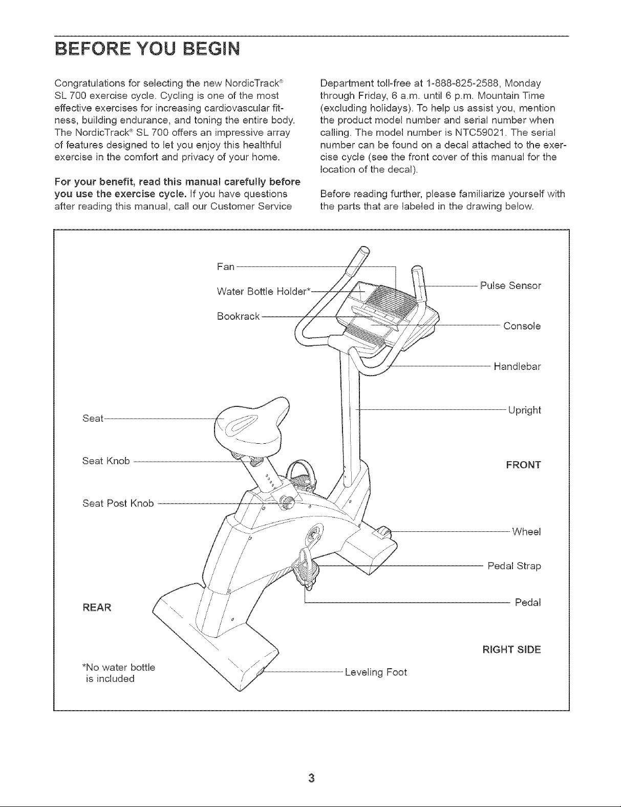
Fan
Bookrack
Water Bottle HoI_
Department toGfree at 1-888-825-2588, Monday
through Friday, 6 a.m. until 6 p.m. Mountain Time
(excluding holidays). To help us assist you, mention
the product model number and serial number when
calling. The model number is NTC59021. The serial
number can be found on a decal attached to the exer-
cise cycle (see the front cover of this manual for the
location of the decal).
Before reading further, please familiarize yourself with
the parts that are labeled in the drawing below.
Pulse Sensor
Console
4
Handlebar
Seat
Seat Knob
Seat Post Knob
REAR
*No water bottle
is included
Upright
FRONT
Wheel
Pedal Strap
Pedal
RIGHT SIDE
Leveling Foot
3
ASSEMBLY
Assembly requires two persons. Place all parts of the exercise cycle in a cleared area and remove the packing
materials. Do not dispose of the packing materials until assembly is completed.
Assembly requires the included tools and your own adjustable wrench ©__../_.
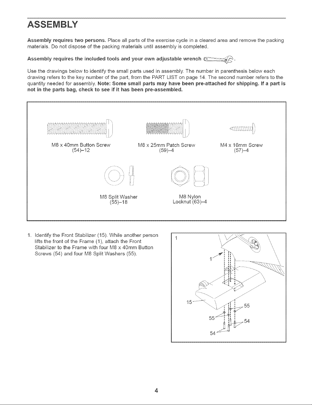
Use the drawings below to identify the small parts used in assembly. The number in parenthesis below each
drawing refers to the key number of the part, from the PART LiST on page 14. The second number refers to the
quantity needed for assembly. Note: Some smaml parts may have been pre°attached for shipping. If a part is
not in the parts bag, check to see if it has been pre-assembled.
M8 x 40mm Button Screw M8 x 25mm Patch Screw M4 x 16mm Screw
(54)=12 (59).4 (57).4
/ 7¸ "\ i_¸ I
" - " ii
. ',, ,,, ..... ;,'ii_
M8 Split Washer
(55)-18
1. identify the Front Stabilizer (15). While another person
lifts the front of the Frame (1), attach the Front
Stabilizer to the Frame with four M8 x 40mm Button
Screws (54) and four M8 Split Washers (55).
M8 Nylon
Locknut (63)-4
4
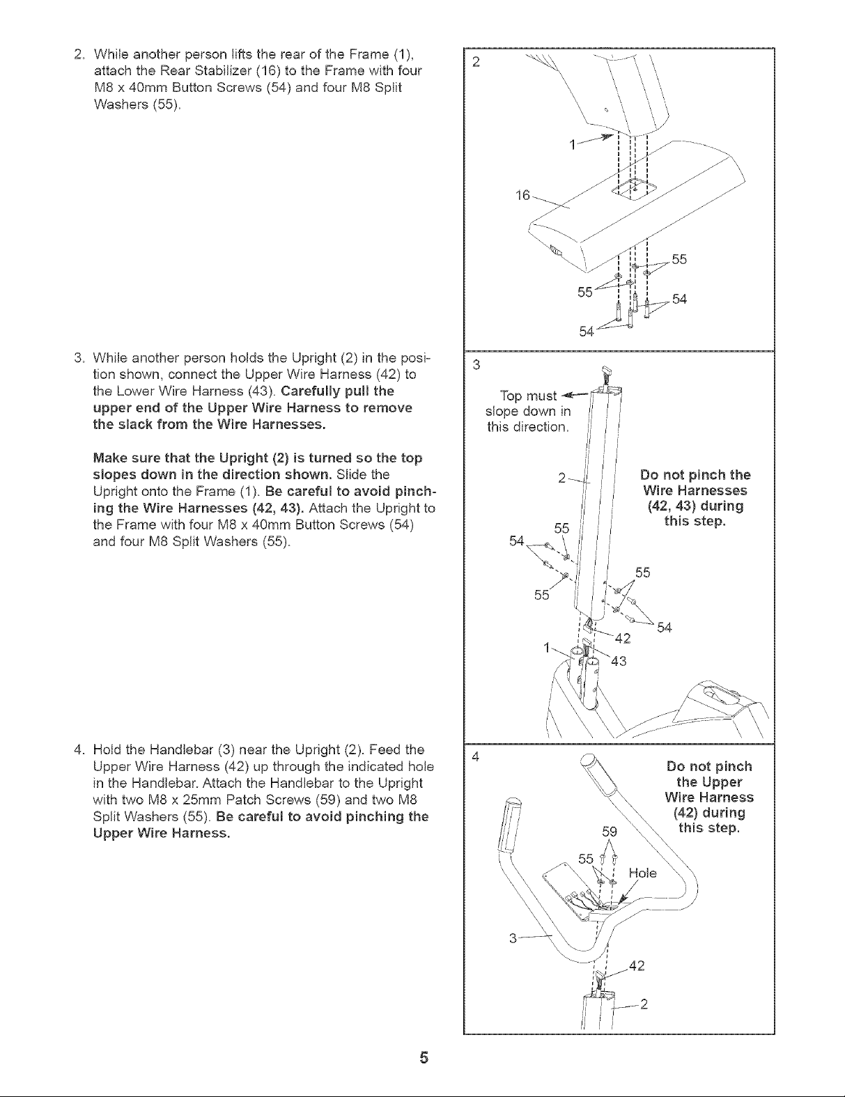
2. While another person lifts the rear of the Frame (1),
attach the Rear Stabilizer (16) to the Frame with four
M8 x 40mm Button Screws (54) and four M8 Split
Washers (55).
3. While another person holds the Upright (2) in the posi-
tion shown, connect the Upper Wire Harness (42) to
the Lower Wire Harness (43). Carefuffy pul! the
upper end of the Upper Wire Harness to remove
the slack from the Wire Harnesses.
Make sure that the Upright (2) is turned so the top
slopes down in the direction shown. Slide the
Upright onto the Frame (1). Be careful to avoid pinch=
ing the Wire Harnesses (42, 43). Attach the Upright to
the Frame with four M8 x 40mm Button Screws (54)
and four M8 Split Washers (55).
\\ \
Top must
slope down in
this direction.
55
54
\\ \ \,
•54
54
Do not pinch the
Wire Harnesses
(42, 43) during
this step.
4. Hold the Handlebar (3) near the Upright (2). Feed the
Upper Wire Harness (42) up through the indicated hole
in the Handlebar. Attach the Handlebar to the Upright
with two M8 x 25mm Patch Screws (59) and two M8
Split Washers (55). Be careful to avoid pinching the
Upper Wire Harness.
55
54
4
Do not pinch
the Upper
Wire Harness
(42) during
this step.
5
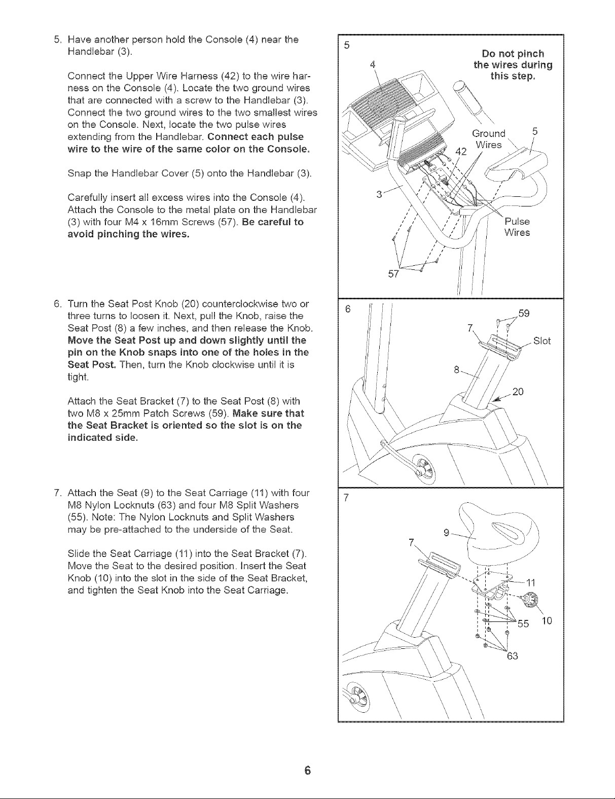
5. Have another person hold the Console (4) near the
Handlebar (3).
Connect the Upper Wire Harness (42) to the wire har=
ness on the Console (4). Locate the two ground wires
that are connected with a screw to the Handlebar (3).
Connect the two ground wires to the two smallest wires
on the Console. Next, locate the two pulse wires
extending from the Handlebar. Connect each pulse
wire to the wire of the same color on the Console.
Snap the Handlebar Cover (5) onto the Handlebar (3).
Carefully insert all excess wires into the Console (4).
Attach the Console to the metal plate on the Handlebar
(3) with four M4 x 16mm Screws (57). Be careful to
avoid pinching the wires.
5
Do not pinch
4
the wires during
this step.
Ground 5
Wires \
Pulse
Wires
J i
J
I
6. Turn the Seat Post Knob (20) counterclockwise two or
three turns to loosen it. Next, pull the Knob, raise the
Seat Post (8) a few inches, and then release the Knob.
Move the Beat Post up and down slightly until the
pin on the Knob snaps into one of the holes in the
Beat Post. Then, turn the Knob clockwise until it is
tight.
Attach the Seat Bracket (7) to the Seat Post (8) with
two M8 x 25mm Patch Screws (59). Make sure that
the Beat Bracket is oriented so the slot is on the
indicated side.
7. Attach the Seat (9) to the Seat Carriage (11) with four
M8 Nylon Locknuts (63) and four M8 Split Washers
(55). Note: The Nylon Locknuts and Split Washers
may be pre=attached to the underside of the Seat.
Slide the Seat Carriage (11) into the Seat Bracket (7).
Move the Seat to the desired position. Insert the Seat
Knob (10) into the slot in the side of the Seat Bracket,
and tighten the Seat Knob into the Seat Carriage.
57
I l
J i
i I
!
///
//'
i7
\
\
\
\
\
\
7
63
\
\
\
\
\
\
\

.
identify the Left Pedal (22), which is marked with an
"L" Using an adjustable wrench, firmly tighten the
Left Pedal counterclockwise into the Left Crank Arm
(24). Tighten the Right Pedal (not shown) clockwise
25
into the Right Crank Arm. Important: Tighten both
Pedats as firmly as possible. After using the
exercise cycle for one week, retighten the
Pedats. For best performance, the Pedals must
be kept tightened.
identify the Left Pedal Strap (25), which is marked
with an "L" Attach the Left Pedal Strap to the Left
Pedal (22), and adjust it to the desired position.
24
Adjust the Right Pedal Strap (not shown) in the
same way.
g.
Make sure that all parts are properly tightened before you use the exercise cycle. Note: After assembly is
completed, some extra parts may be left over. Place a mat beneath the exercise cycle to protect the floor.
iNSTALLiNG THE RECEIVER FOR THE OPTIONAL CHEST PULSE SENSOR
if you purchase the optional chest pulse sensor (see page 19), follow the steps below to install the receiver
included with the chest pulse sensor.
Remove the access door from the underside of the
Console (4). You may need to use a small standard
screwdriver to remove the access door.
Slide the receiver onto the indicated plastic pin on the
Console (4); make sure that the receiver is oriented
exactly as shown. Locate the two small screws included
with the chest pulse sensor. Attach the receiver to the
Console with the two screws as shown.
Connect the wire on the receiver to the indicated wire on
the Console (4).
Reattach the access door. Make sure that no wires are
pinched. Note: The other wires included with the chest
pulse sensor may be discarded.
//
////
Pin
Wire
I I
I o
I
//
Screws
Receiver
7
HOW TO OPERATE THE EXERCmSE CYCLE
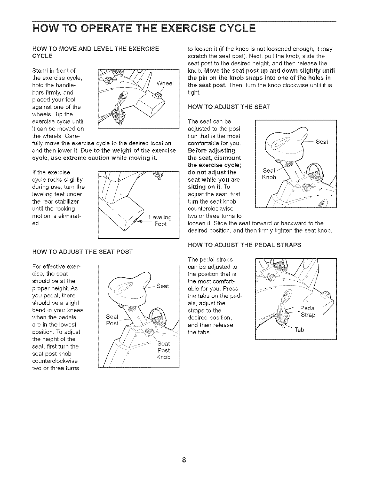
HOW TO MOVE AND LEVEL THE EXERCISE
CYCLE
Stand in front of
the exercise cycle,
hold the handle- Wheel
bars firmly, and
placed your foot
against one of the
wheels. Tip the
exercise cycle until
it can be moved on
the wheels. Care-
fully move the exercise cycle to the desired location
and then lower it. Due to the weight of the exercise
cycle, use extreme caution while moving it.
if the exercise
cycle rocks slightly
during use, turn the
leveling feet under
the rear stabilizer
until the rocking
motion is eliminat-
ed.
Foot
to loosen it (if the knob is not loosened enough, it may
scratch the seat post). Next, pull the knob, slide the
seat post to the desired height, and then release the
knob. Move the seat post up and down slightly until
the pin on the knob snaps into one of the holes in
the seat post. Then, turn the knob clockwise until it is
tight.
HOW TO ADJUST THE SEAT
The seat can be
adjusted to the posi=
tion that is the most
comfortable for you.
Before adjusting
the seat, dismount
the exercise cycle;
do not adjust the
seat while you are
sitting on it. To
adjust the seat, first
turn the seat knob
counterclockwise
two or three turns to
loosen it. Slide the seat forward or backward to the
desired position, and then firmly tighten the seat knob.
HOW TO ADJUST THE SEAT POST
For effective exer-
cise, the seat
should be at the
proper height. As
you pedal, there
should be a slight
bend in your knees
when the pedals
are in the lowest
position. To adjust
the height of the
seat, first turn the
seat post knob
counterclockwise
two or three turns
Knob
HOW TO ADJUST THE PEDAL STRAPS
The pedal straps
can be adjusted to
the position that is
the most comfort-
able for you. Press
the tabs on the ped-
als, adjust the
straps to the
desired position,
and then release
the tabs.
Strap
Tab
8
 Loading...