


APPLICANT: Alcatel-Lucent USA Inc. -13 - FCC ID: AS5BBTRX-21
Exhibit 6 – Instruction Book
Confidential
SECTION 2.1033(c) (3)
A copy of the installation and operating instructions to be furnished the user. A draft copy of the instructions may be
submitted if the actual document is not available. The actual document shall be furnished to the FCC when it becomes
available.
Response: The installation and operating instructions for the Alcatel-Lucent’s PCS LTE 9764 Metro Cell Outdoor
Transceiver System FCC ID: AS5BBTRX-21 is attached.
The Installation Manual in this exhibit, Alcatel-Lucent 9764 Metro Cell Outdoor LTE 2x1W and 2x2W Hardware
Installation, 3MN-01707-0002-RJZZA Issue 3.05 | October 2014, is not furnished to the user, except under very
exceptional and very limited circumstances. This manual contains highly proprietary circuit, equipment and
architecture descriptions that must not be made available for public inspection.
The cover/title page is explicitly labeled:
“Alcatel-Lucent – Internal
Proprietary – Use pursuant to Company instruction”.
This information is proprietary both to Alcatel- Lucent and to Alcatel- Lucent’s contracted manufacturer/supplier.
(ALCATEL-LUCENT USA CONFIDENTIAL PROPRIETARY INFORMATION)
Alcatel-Lucent USA Inc. - Proprietary
Use pursuant to Company Instructions.
13

Proprietary Use pursuant to Company instruction
Title page
D
RAFT
Alcatel-Lucent 9764
Metro Cell Outdoor LTE 2x1W and 2x2W
Hardware Installation
3MN-01707-0002-RJZZA
Issue 3.05 | October 2014
Alcatel-Lucent – Internal
Proprietary – Use pursuant to Company instruction
D
RAFT

Proprietary Use pursuant to Company instruction
Legal notice
Legal notice
Alcatel, Lucent, Alcatel-Lucent and the Alcatel-Lucent logo are trademarks of Alcatel-Lucent. All other trademarks are the property of their respective
RAFT
owners.
The information presented is subject to change without notice. Alcatel-Lucent assumes no responsibility for inaccuracies contained herein.
D
Copyright © 2014 Alcatel-Lucent. All rights reserved.
Contains proprietary/trade secret information which is the property of Alcatel-Lucent and must not be made available to, or copied or used by anyone outside
Alcatel-Lucent without its written authorization.
RAFT
D
Proprietary – Use pursuant to Company instruction
Alcatel-Lucent – Internal

D
Contents
About this document
Purpose .......................................................................................................................................................................................... xiiixiii
What's new
Intended audience
Supported systems
How to use this document
Safety information
Prerequisites
Conventions used
Related information
................................................................................................................................................................................... xiiixiii
................................................................................................................................................................................. xivxiv
RAFT
...................................................................................................................................................................... xivxiv
..................................................................................................................................................................... xivxiv
....................................................................................................................................................... xivxiv
..................................................................................................................................................................... xivxiv
......................................................................................................................................................................... xvxv
................................................................................................................................................................. xviixvii
Document support
Technical support
How to order
How to comment
...................................................................................................................................................................... xixxix
....................................................................................................................................................................... xixxix
.................................................................................................................................................................................. xxxx
.......................................................................................................................................................................... xxxx
1 Safety statements
Overview
Structure of safety statements
Safety
Safety - specific hazards
Product safety
...................................................................................................................................................................................... 1-11-1
............................................................................................................................................... 1-21-2
........................................................................................................................................................................................... 1-41-4
......................................................................................................................................................... 1-51-5
............................................................................................................................................................................. 1-91-9
2 Product overview
Overview
Functional description
....................................................................................................................................................................................................................................
Alcatel-Lucent 9764 MCO
3MN-01707-0002-RJZZA
Issue 3.05 October 2014
...................................................................................................................................................................................... 2-12-1
............................................................................................................................................................. 2-22-2
Proprietary – Use pursuant to Company instruction
Alcatel-Lucent – Internal
iii
D
RAFT

Contents
....................................................................................................................................................................................................................................
RAFT
Physical description ................................................................................................................................................................. 2-42-4
D
Supported installation options
Hardware and ancillary items
........................................................................................................................................... 2-132-13
............................................................................................................................................ 2-172-17
3 Installation of the 9764 Metro Dock
Overview
...................................................................................................................................................................................... 3-13-1
9764 Metro Dock pre-installation
Overview
...................................................................................................................................................................................... 3-23-2
9764 Metro Dock Pre-installation information
Pole mount installation requirements
Wall mount installation requirements
Pair mount and daisy chain requirements
9764 Metro Dock installation
Overview
................................................................................................................................................................................... 3-183-18
.............................................................................................................. 3-33-3
................................................................................................................................ 3-53-5
................................................................................................................................ 3-93-9
...................................................................................................................... 3-133-13
Procedure 3-1: Pole mount the 9764 Metro Dock
...................................................................................................... 3-193-19
Procedure 3-2: Pole mount the 9764 Metro Dock using optional tilt brackets
Procedure 3-3: Wall mount the 9764 Metro Dock
..................................................................................................... 3-353-35
Procedure 3-4: Wall mount the 9764 Metro Dock using optional tilt brackets
Procedure 3-5: Pole mount the 9764 Metro Dock in a pair configuration
Procedure 3-6: Wall mount the 9764 Metro Dock in a pair configuration
........................................................ 3-543-54
........................................................ 3-713-71
9764 Metro Dock cabling
Overview
Procedure 3-7: 9764 Metro Dock ground cabling
Procedure 3-8: 9764 Metro Dock Ethernet cabling - fiber optic
Procedure 3-9: 9764 Metro Dock Ethernet cabling - electrical
................................................................................................................................................................................... 3-893-89
...................................................................................................... 3-903-90
.......................................................................... 3-923-92
............................................................................. 3-993-99
9764 Metro Dock post-installation
................................................ 3-253-25
............................................... 3-403-40
Overview
....................................................................................................................................................................................................................................
iv
RAFT
D
................................................................................................................................................................................. 3-1113-111
Proprietary – Use pursuant to Company instruction
Alcatel-Lucent – Internal
Alcatel-Lucent 9764 MCO
3MN-01707-0002-RJZZA
Issue 3.05 October 2014

Contents
....................................................................................................................................................................................................................................
Procedure 3-10: Final installation activities and checks ........................................................................................ 3-1123-112
4 Installation of the 9764 MCO module
D
RAFT
Overview
...................................................................................................................................................................................... 4-14-1
9764 MCO pre-installation
Overview
Pre-installation information
...................................................................................................................................................................................... 4-24-2
.................................................................................................................................................. 4-34-3
9764 MCO cabling
Overview
...................................................................................................................................................................................... 4-44-4
Procedure 4-1: Connect external RF antenna to the Alcatel-Lucent 9764 MCO LTE 2x2W
Procedure 4-2: Connect GPS antenna
Procedure 4-3: 9764 MCO module ground cabling
Site power requirements (AC)
Site power requirements (DC)
Product power requirements
........................................................................................................................................... 4-214-21
........................................................................................................................................... 4-244-24
............................................................................................................................................... 4-274-27
............................................................................................................................... 4-74-7
................................................................................................... 4-184-18
....................... 4-54-5
Procedure 4-4: Connect power cable
.............................................................................................................................. 4-294-29
9764 MCO installation
Overview
Procedure 4-5: Attach 9764 MCO module to 9764 Metro Dock
Procedure 4-6: Orient 9764 MCO module
................................................................................................................................................................................... 4-404-40
.......................................................................... 4-414-41
................................................................................................................... 4-484-48
9764 MCO post-installation
Overview
Procedure 4-7: Post installation activities
Procedure 4-8: Power on the 9764 MCO
................................................................................................................................................................................... 4-504-50
..................................................................................................................... 4-514-51
...................................................................................................................... 4-524-52
A LED State Description
Overview
LED status for 9764 MCO LTE
....................................................................................................................................................................................................................................
Alcatel-Lucent 9764 MCO
3MN-01707-0002-RJZZA
Issue 3.05 October 2014
..................................................................................................................................................................................... A-1A-1
......................................................................................................................................... A-2A-2
Alcatel-Lucent – Internal
Proprietary – Use pursuant to Company instruction
D
RAFT
v

Contents
....................................................................................................................................................................................................................................
B Installation of the 9764 MCO Wi-Fi AP
RAFT
D
Overview
..................................................................................................................................................................................... B-1B-1
Physical description
................................................................................................................................................................ B-2B-2
9764 MCO Wi-Fi AP pre-installation information
Procedure B-1: Remove 9764 MCO module from 9764 Metro Dock
Procedure B-2: Attach 9764 MCO Wi-Fi AP module to 9764 MCO module
LED state description - 9764 MCO Wi-Fi AP
C Product conformance statements
Overview
..................................................................................................................................................................................... C-1C-1
United States compliance
Introduction
................................................................................................................................................................................ C-2C-2
Federal Communications Commission
Product safety and RF exposure
......................................................................................................................................... C-4C-4
...................................................................................................... B-8B-8
................................................................. B-9B-9
................................................. B-19B-19
............................................................................................................ B-25B-25
............................................................................................................................ C-3C-3
FDA/IEC optical transmitter product compliance statements
Eco-environmental statements
European Union
Introduction
CE marking
................................................................................................................................................................................ C-7C-7
................................................................................................................................................................................ C-8C-8
EMC and radio spectrum compliance
Product safety and RF exposure
Eco-environmental statements
D Document issue history
Overview
Document issue history
..................................................................................................................................................................................... D-1D-1
......................................................................................................................................................... D-2D-2
Glossary
................................................................................. C-5C-5
............................................................................................................................................ C-6C-6
.............................................................................................................................. C-9C-9
....................................................................................................................................... C-10C-10
.......................................................................................................................................... C-13C-13
Index
....................................................................................................................................................................................................................................
vi
RAFT
D
Proprietary – Use pursuant to Company instruction
Alcatel-Lucent – Internal
Alcatel-Lucent 9764 MCO
3MN-01707-0002-RJZZA
Issue 3.05 October 2014

D
List of tables
1 Document changes from Issue 3.03, September 2014 ................................................................................. xiiixiii
2 Terminology .................................................................................................................................................................. xvxv
3 Related documents ................................................................................................................................................... xviixvii
2-1 GPS antenna options .............................................................................................................................................. 2-112-11
3-1 Pole mount installation kits and brackets ......................................................................................................... 3-63-6
3-2 Wall mount installation brackets .......................................................................................................................... 3-93-9
4-1 Power materials ....................................................................................................................................................... 4-274-27
B-1 9764 MCO Wi-Fi AP physical characteristics ............................................................................................... B-4B-4
B-2 9764 MCO Wi-Fi AP LEDs during boot-up ................................................................................................. B-25B-25
B-3 9764 MCO Wi-Fi AP LEDs based on Admin status and WLAN mapping ...................................... B-26B-26
RAFT
B-4 9764 MCO Wi-Fi AP LEDs during normal operation states .................................................................. B-27B-27
C-1 Distances corresponding to reference levels for the general public and workers at maximum Tx
power
C-2 Distances corresponding to reference levels for the general public and workers at maximum Tx
power
D-1 Document changes from Issue 3, September 2014 ...................................................................................... D-2D-2
D-2 Document changes from Issue 2,June 2014 .................................................................................................... D-2D-2
D-3 Document changes from Issue 1.06, May 2014 ............................................................................................ D-3D-3
D-4 Document changes from Issue 1.05, May 2014 ............................................................................................ D-3D-3
D-5 Document changes from Issue 1.04, April 2014 ........................................................................................... D-4D-4
D-6 Document changes from Issue 1.03, February 2014 ................................................................................... D-4D-4
D-7 Document changes from Issue 1.02, January 2014 ...................................................................................... D-4D-4
D-8 Document changes from Issue 1.01, December 2013 ................................................................................. D-5D-5
D-9 Document changes from Issue 1, November 2013 ...................................................................................... D-5D-5
....................................................................................................................................................................................................................................
Alcatel-Lucent 9764 MCO
3MN-01707-0002-RJZZA
Issue 3.05 October 2014
....................................................................................................................................................................... C-11C-11
....................................................................................................................................................................... C-12C-12
Proprietary – Use pursuant to Company instruction
Alcatel-Lucent – Internal
vii
D
RAFT

List of tables
....................................................................................................................................................................................................................................
RAFT
D
....................................................................................................................................................................................................................................
viii
RAFT
D
Proprietary – Use pursuant to Company instruction
Alcatel-Lucent – Internal
Alcatel-Lucent 9764 MCO
3MN-01707-0002-RJZZA
Issue 3.05 October 2014

D
List of figures
2-1 9764 Metro Dock and 9764 MCO LTE 2x1W and Alcatel-Lucent 9764 Metro Cell Outdoor LTE
2x2W
........................................................................................................................................................................... 2-42-4
2-2 9764 MCO LTE with 9764 MCO Wi-Fi AP .................................................................................................... 2-52-5
2-3 9764 MCO LTE module connection interfaces .............................................................................................. 2-92-9
2-4 9764 MCO LTE module connection interfaces - double lug ground point detail .............................. 2-92-9
2-5 Installation examples ............................................................................................................................................. 2-132-13
2-6 9764 MCO Wi-Fi AP module attached to 9764 MCO LTE module (front view) ........................... 2-142-14
2-7 9764 MCO daisy chain installation example ................................................................................................ 2-152-15
2-8 9764 MCO pair-mount installation example ................................................................................................. 2-162-16
3-1 Pole mount banding and brackets ........................................................................................................................ 3-63-6
RAFT
3-2 9764 Metro Dock pole mount using screws .................................................................................................... 3-73-7
3-3 9764 Metro Dock pole mount using banding .................................................................................................. 3-83-8
3-4 Double 9764 Metro Dock pole mount ............................................................................................................... 3-83-8
3-5 Wall mount brackets ............................................................................................................................................... 3-103-10
3-6 9764 Metro Dock wall mount (no tilt) ............................................................................................................. 3-113-11
3-7 9764 Metro Dock wall mount (with tilt) ......................................................................................................... 3-113-11
3-8 Double 9764 Metro Dock wall mount ............................................................................................................. 3-123-12
4-1 External GPS antenna configuration .................................................................................................................. 4-74-7
4-2 External GPS antenna connector ....................................................................................................................... 4-104-10
4-3 GPS antenna connection ...................................................................................................................................... 4-104-10
4-4 Weatherproof tape placement for external GPS antenna .......................................................................... 4-114-11
4-5 Internal and external GPS antenna connectors ............................................................................................. 4-124-12
4-6 GPS antenna connection ...................................................................................................................................... 4-134-13
4-7 Weatherproof tape placement for external GPS antenna .......................................................................... 4-144-14
....................................................................................................................................................................................................................................
Alcatel-Lucent 9764 MCO
3MN-01707-0002-RJZZA
Issue 3.05 October 2014
Proprietary – Use pursuant to Company instruction
Alcatel-Lucent – Internal
ix
D
RAFT

List of figures
....................................................................................................................................................................................................................................
RAFT
4-8 Bridge cable between external and internal GPS antenna connectors ................................................. 4-154-15
D
4-9 Internal/external GPS antenna connector ....................................................................................................... 4-164-16
4-10 Weatherproof tape placement for external GPS antenna .......................................................................... 4-174-17
4-11 connection interfaces ............................................................................................................................................. 4-294-29
A-1 Location of LED ....................................................................................................................................................... A-2A-2
B-1 9764 MCO Wi-Fi AP attached to 9764 MCO hardware variants ............................................................ B-2B-2
B-2 9764 MCO Wi-Fi AP - closed housing ............................................................................................................. B-3B-3
B-3 9764 MCO Wi-Fi AP - cutaway view ............................................................................................................... B-3B-3
B-4 9764 MCO Wi-Fi AP connection point on 9764 MCO .............................................................................. B-5B-5
B-5 9764 MCO Wi-Fi AP connected to 9764 MCO (cutaway side view) ................................................... B-5B-5
B-6 9764 Metro Dock to LTE 9764 MCO module grounding cable ........................................................... B-13B-13
B-7 Key extension .......................................................................................................................................................... B-13B-13
B-8 Pull 9764 MCO module from Metro Dock ................................................................................................... B-16B-16
B-9 AC power line connector ..................................................................................................................................... B-16B-16
B-10 DC power line connector ..................................................................................................................................... B-17B-17
B-11 9764 MCO Wi-Fi AP module attached to 9764 MCO module .............................................................. B-17B-17
B-12 Wi-Fi AP connector cover on 9764 MCO module ..................................................................................... B-21B-21
B-13 Wi-Fi AP connector on 9764 MCO module ................................................................................................. B-21B-21
B-14 9764 MCO Wi-Fi AP module attached to 9764 MCO module .............................................................. B-22B-22
....................................................................................................................................................................................................................................
x
RAFT
D
Proprietary – Use pursuant to Company instruction
Alcatel-Lucent – Internal
Alcatel-Lucent 9764 MCO
3MN-01707-0002-RJZZA
Issue 3.05 October 2014

D
List of procedures
3 Installation of the 9764 Metro Dock
3-1
3-2 Pole mount the 9764 Metro Dock using optional tilt brackets ............................................................... 3-253-25
3-3 Wall mount the 9764 Metro Dock ..................................................................................................................... 3-353-35
3-4 Wall mount the 9764 Metro Dock using optional tilt brackets ............................................................... 3-403-40
3-5 Pole mount the 9764 Metro Dock in a pair configuration ........................................................................ 3-543-54
3-6 Wall mount the 9764 Metro Dock in a pair configuration ....................................................................... 3-713-71
3-7 9764 Metro Dock ground cabling ..................................................................................................................... 3-903-90
3-8 9764 Metro Dock Ethernet cabling - fiber optic .......................................................................................... 3-923-92
3-9 9764 Metro Dock Ethernet cabling - electrical ............................................................................................ 3-993-99
Pole mount the 9764 Metro Dock ..................................................................................................................... 3-193-19
RAFT
3-10 Final installation activities and checks .......................................................................................................... 3-1123-112
4 Installation of the 9764 MCO module
4-1
4-2 Connect GPS antenna ............................................................................................................................................... 4-74-7
4-3 9764 MCO module ground cabling .................................................................................................................. 4-184-18
4-4 Connect power cable .............................................................................................................................................. 4-294-29
4-5 Attach 9764 MCO module to 9764 Metro Dock ......................................................................................... 4-414-41
4-6 Orient 9764 MCO module .................................................................................................................................. 4-484-48
4-7 Post installation activities ..................................................................................................................................... 4-514-51
4-8 Power on the 9764 MCO ...................................................................................................................................... 4-524-52
B Installation of the 9764 MCO Wi-Fi AP
B-1
B-2 Attach 9764 MCO Wi-Fi AP module to 9764 MCO module ................................................................. B-19B-19
....................................................................................................................................................................................................................................
Alcatel-Lucent 9764 MCO
3MN-01707-0002-RJZZA
Issue 3.05 October 2014
Connect external RF antenna to the Alcatel-Lucent 9764 MCO LTE 2x2W ...................................... 4-54-5
Remove 9764 MCO module from 9764 Metro Dock ................................................................................. B-9B-9
Alcatel-Lucent – Internal
Proprietary – Use pursuant to Company instruction
xi
D
RAFT

List of procedures
....................................................................................................................................................................................................................................
RAFT
D
....................................................................................................................................................................................................................................
xii
RAFT
D
Proprietary – Use pursuant to Company instruction
Alcatel-Lucent – Internal
Alcatel-Lucent 9764 MCO
3MN-01707-0002-RJZZA
Issue 3.05 October 2014

Aboutthis documentAbout this document
Purpose
The purpose of this document is to provide hardware installation instructions for an
Alcatel-Lucent 9764 Metro Cell Outdoor LTE 2x1W and an Alcatel-Lucent 9764 Metro
Cell Outdoor LTE 2x2W.
Procedures are provided for mounting, grounding, powering, and cabling the 9764 MCO
LTE 2x1W and the 9764 MCO LTE 2x2W.
D
RAFT
What's new
This is Issue 3.05 of Alcatel-Lucent Metro Cell Outdoor LTE 2x1W and 2x2W Hardware
Installation, 3MN-01707-0002-RJZZA.
The major changes introduced in this issue of the document are described in the following
paragraphs. Changes introduced in prior issues of the document are shown in
Appendix
D, “Document issue history”
Issue 3.05 (October 2014) - Document changes from the previous release
The document changes from Issue 3.03, September 2014 are shown in the following
table:
Table 1 Document changes from Issue 3.03, September 2014
Feature/enhancement Description Location
Documentation changes
Connect GPS antenna Added information and steps for
using weatherproof tape when
attaching external GPS antenna.
“Connect external GPS antenna - B25, B7 or B2
MCO” (p. 4-9)
“Connect external GPS antenna to MCO - B3
MCO” (p. 4-12)
“Connect internal/external GPS antenna to
Alcatel-Lucent 9764 MCO LTE 2x2W” (p. 4-15)
Hardware and
Ancillary items
...................................................................................................................................................................................................................................
Alcatel-Lucent 9764 MCO
3MN-01707-0002-RJZZA
Issue 3.05 October 2014
Added information about
weatherproof tape when attaching
external GPS antenna in the External
antenna – GPS table.
Alcatel-Lucent – Internal
Proprietary – Use pursuant to Company instruction
“Hardware and ancillary items” (p. 2-17)
xiii
D
RAFT

About this document
....................................................................................................................................................................................................................................
Intended audience
RAFT
D
Supported systems
The audience for this document is Installation personnel.
This document applies to the following Alcatel-Lucent 9764 Metro Cell Outdoor LTE
2x1W and Alcatel-Lucent 9764 Metro Cell Outdoor LTE 2x2W products:
• Alcatel-Lucent 9764 Metro Cell Outdoor V1.0 B25 LTE 2x1W
• Alcatel-Lucent 9764 Metro Cell Outdoor V1.1 B2 LTE 2x1W
• Alcatel-Lucent 9764 MCO V1.1 B2/B25 LTE 2x1W
• Alcatel-Lucent 9764 Metro Cell Outdoor V1.1 B7 LTE 2x1W
• Alcatel-Lucent 9764 Metro Cell Outdoor V1.1 B2 LTE 2x2W
• Alcatel-Lucent 9764 Metro Dock.
How to use this document
Start with the first chapter and work through the manual to the end. Once you have done
this, you will have carried out the hardware installation completely and in the proper
sequence.
Prior to installing the equipment, the installer should be familiar with the safety
precautions, warnings, and product conformance statements. Required tools and materials
recommended for installation, and a process checklist, are listed in topic “Pre-installation
information” .
Safety information
For your safety, this document contains safety statements. Safety statements are given at
points where risks of damage to personnel, equipment, and operation may exist. Failure to
follow the directions in a safety statement may result in serious consequences.
Prerequisites
None
....................................................................................................................................................................................................................................
xiv
RAFT
D
Proprietary – Use pursuant to Company instruction
Alcatel-Lucent – Internal
Alcatel-Lucent 9764 MCO
3MN-01707-0002-RJZZA
Issue 3.05 October 2014

About this document
....................................................................................................................................................................................................................................
Conventions used
Vocabulary conventions
The following vocabulary conventions are also used when referring to Alcatel-Lucent
products:
Table 2 Terminology
Term Description/Meaning
9764 MCO The 9764 MCO consists of the following modules: 9764 Metro
Dock module, and the 9764 MCO WCDMA module.
9764 Metro Dock Refers to the Alcatel-Lucent 9764 Metro Dock, a module supporting
backhaul for the 9764 MCO.
9764 MCO LTE Refers to the module that contains the complete base station,
including baseband unit, radio unit and antenna. It is attached to the
front of the 9764 Metro Dock to form the 9764 MCO.
D
RAFT
9764 MCO V1.1
B2/B25 LTE 2x1W
9764 MCO V1.1 B2
LTE 2x2W
Refers to the Band 2/Band 25 (combined) 2x1W variant of the 9764
MCO LTE that is the focus of this document.
Refers to the Band 2 2x2W variant of the 9764 MCO LTE that is the
focus of this document.
Typographical conventions
The typographical conventions used in this document are described in the following table.
Appearance Description
emphasis Text that is emphasized
document titles Titles of books or other documents
graphical user interface text Text that is displayed in a graphical user
interface
variables
A value or command-line parameter that the
user provides
Technical conventions
Lengths and other measurements are given in metric units, with non-metric units given as
equivalents for use in non-metric markets.
....................................................................................................................................................................................................................................
Alcatel-Lucent 9764 MCO
3MN-01707-0002-RJZZA
Issue 3.05 October 2014
Proprietary – Use pursuant to Company instruction
Alcatel-Lucent – Internal
xv
D
RAFT

About this document
....................................................................................................................................................................................................................................
RAFT
D
For manufactured parts, the following system of conventions is used:
• Metric sizes of nuts, bolts, flat washers, and lock washers are identified by an
uppercase letter M followed immediately by a size in millimeters (example: M10)
• American fractional sizes of nuts, bolts, anchor bolts, and washers are identified by a
number followed immediately by a double apostrophe (example: 3/8"). In the case of
lengths measured in feet, “2 feet” is used rather than “2'” so that the single apostrophe
is not overlooked.
The illustrations in this document do not contain all details and exceptions, but are
intended to highlight main points. Dimensions are usually shown in millimeters, with
inches in parenthesis. As an example, 680.0 (26.77) equals 680 millimeters or 26.77
inches.
Wire gauges are specified in metric units. Equivalent sizes in the American Wire Gauge
(AWG) system are given in the following table:
Standard cross-sections and wire diameter of round copper conductors
The following table is from CEI/IEC 60947-1:2004, Table 1, Standard cross-sections of
2
round copper conductors and approximate relationship between mm
and AWG/kcmil
sizes for reference. Additional wire sizes are included in this document as appropriate for
the topic.
ISO rated cross-sectional area (mm2) AWG/kcmil size
0.2 24
0.34 22
0.5 20
0.75 18
1-
1.5 16
2.5 14
412
610
10 8
16 6
25 4
35 2
-1
50 0 (1/0)
70 00 (2/0)
....................................................................................................................................................................................................................................
xvi
RAFT
D
Proprietary – Use pursuant to Company instruction
Alcatel-Lucent – Internal
Alcatel-Lucent 9764 MCO
3MN-01707-0002-RJZZA
Issue 3.05 October 2014

About this document
....................................................................................................................................................................................................................................
ISO rated cross-sectional area (mm2) AWG/kcmil size
95 000 (3/0)
- 0000 (4/0)
120 250 kcmil
150 300 kcmil
185 350 kcmil
- 400 kcmil
240 500 kcmil
300 600 kcmil
NOTE: The dash, when it appears, counts as a size when considering connecting capacity (see
7.1.7.2 in the standard).
Related information
D
RAFT
For information on subjects related to the content of this document, refer to the
documents listed in the following table:
Table 3 Related documents
Refer to this document At this location For more information
on
Alcatel-Lucent 9764 Metro Cell
Outdoor LTE 2x1W and 2x2W Site
Preparation, 3MN-01707-0001-
RJZZA
Alcatel-Lucent 9764 Metro Cell
Outdoor LTE 2x1W and 2x2W
Technical Description
9YZ-04152-0056- DEZZA
(LR13.3.L)
9YZ-05817-0056- DEZZA
(LR14.1.L)
Alcatel-Lucent 9764 Metro Cell
Outdoor LTE 2x1W and 2x2W
Maintenance and Troubleshooting
9YZ-04152-0057-REZZA
(LR13.3.L)
9764 MCO LTE (Metro Cell Outdoor for
LTE)
(https://support.alcatel-lucent.com/
portal/productContent.do?entryId=10000000003997
)
9764 MCO LTE (Metro Cell Outdoor for
LTE)
(https://support.alcatel-lucent.com/
portal/productContent.do?entryId=10000000003997
)
9764 MCO LTE (Metro Cell Outdoor for
LTE)
(https://support.alcatel-lucent.com/
portal/productContent.do?entryId=10000000003997
)
9764 MCO LTE 2x1W site
preparation
9764 MCO LTE 2x1W
technical overview
9764 MCO LTE 2x1W
maintenance and
troubleshooting
9YZ-05817-0057-REZZA
(LR14.1.L)
....................................................................................................................................................................................................................................
Alcatel-Lucent 9764 MCO
3MN-01707-0002-RJZZA
Issue 3.05 October 2014
Proprietary – Use pursuant to Company instruction
Alcatel-Lucent – Internal
xvii
D
RAFT

About this document
....................................................................................................................................................................................................................................
RAFT
D
Refer to this document At this location For more information
Table 3 Related documents (continued)
on
Alcatel-Lucent 9772 Wi-Fi Service
Controller V1.0 L Hardware
Installation, 3MN-01840-0001-
RJZZA
Alcatel-Lucent 9764 and 9772
Metro Cell Outdoor Wi-Fi AP and
Wi-Fi Service Controller, Release
WA5.5, System Reference Guide,
3MN-01840-0002-RKZZA
Alcatel-Lucent 9764 and 9772,
Metro Cell Outdoor Wi-Fi AP and
Wi-Fi Service Controller, Release
WA 5.5, CLI Reference Guide,
3MN-01840-0003-RKZZA
Library for LTE End-to-End
Solution
OnLine Customer Support (OLCS)
(http://support.alcatel-lucent.com)
OnLine Customer Support (OLCS)
(http://support.alcatel-lucent.com)
OnLine Customer Support (OLCS)
(http://support.alcatel-lucent.com)
LTE End-to-End Solution
(https://infoproducts.alcatel-lucent.com/
aces/cgi-bin/dbaccessproddoc.cgi.edit?
entryId=1-0000000001078
)
Instructions for installing
the 9772 WiSC-L
hardware and accessing its
management interfaces.
Instructions for accessing
and using the web-based
graphic user interface
(GUI) to
manage/administer the
9772 Wi-Fi Service
Controller and 9764 MCO
Wi-Fi Access Point
Instructions for accessing
and using command line
interface (CLI) to
manage/administer the
9772 Wi-Fi Service
Controller and 9764 MCO
Wi-Fi Access Point.
The full collection of
documents in the LTE
collection
Alcatel-Lucent LTE Radio Access
Network (RAN) eNodeB Macro
and Metro Products Release FDD
Release Notes
LTE End-to-End Solution
(https://infoproducts.alcatel-lucent.com/
aces/cgi-bin/dbaccessproddoc.cgi.edit?
entryId=1-0000000001078
)
Release specific software
and feature status
information
9YZ-05817-0001-FMZZA
(LR13.3.L)
9YZ-04152-0001-FMZZA
(LR14.1.L)
9764 lightRadio Metro Cell
Outdoor “Family” Model Offer
Provisioning Guide,
Subject to non-disclosure agreement and
available from Alcatel-Lucent
representatives
Product ordering codes
BCR/IRC/APP/038681
....................................................................................................................................................................................................................................
xviii
RAFT
D
Proprietary – Use pursuant to Company instruction
Alcatel-Lucent – Internal
Alcatel-Lucent 9764 MCO
3MN-01707-0002-RJZZA
Issue 3.05 October 2014

About this document
....................................................................................................................................................................................................................................
Table 3 Related documents (continued)
Refer to this document At this location For more information
on
D
RAFT
FDD eNodeB Product Engineering
Guide, LTE/DCL/APP/041927
Grounding and Lightning
Protection Guidelines for
Alcatel-Lucent Wireless System
Cell Sites, 401-200-115
Standard for Installation of
Lightning Protection Systems,
NFPA
Recommended Practices on Surge
Voltages in Low Voltage AC Power
Circuits, IEEE C62.41 (Latest
Edition)
Document support
Subject to non-disclosure agreement and
available from Alcatel-Lucent
representatives
OnLine Customer Support (OLCS)
(http://support.alcatel-lucent.com)
ANSI web site (http://webstore.ansi.org/
default.aspx
IEEE web site (http://www.ieee.org/index.
html
)
)
The different
Alcatel-Lucent LTE
eNodeB hardware
configurations and the
related engineering rules
and guidelines.
Grounding and Lightning
protection systems
Lightning protection
systems
Power
For support in using this or any other Alcatel-Lucent document, contact Alcatel-Lucent at
the following telephone numbers.
From United States
• If you are using a landline, a cellular phone or VoIP, dial this number: 1-888-582-3688
From other countries
• If you are using a cellular phone or VoIP, dial this number: +1-630-224-2485
• If you are using a landline (phone without a plus [+] character), replace the plus sign
with your country's exit code. Dial this number: Exit code for the country of origin:
1-630-224-2485. See the country-specific exit codes listed
here.
These numbers apply for document support only. Please see the section “Technical
support” for details about product hardware, software, and technical support.
Technical support
For technical support, contact your local Alcatel-Lucent customer support team. See the
Alcatel-Lucent Support web site (http://www.alcatel-lucent.com/support/) for contact
information.
....................................................................................................................................................................................................................................
Alcatel-Lucent 9764 MCO
3MN-01707-0002-RJZZA
Issue 3.05 October 2014
Proprietary – Use pursuant to Company instruction
Alcatel-Lucent – Internal
xix
D
RAFT

About this document
....................................................................................................................................................................................................................................
How to order
RAFT
D
To order Alcatel-Lucent documents, contact your local sales representative or use Online
Customer Support (OLCS) (http://support.alcatel-lucent.com).
How to comment
Note to reviewers: The following "How to comment" text will appear in the final
document when it is published. However, the feedback method described below is for use
only on final documents. Please send your review comments to the author using the
process you were given when you received this draft document.
To comment on this document, go to the
lucent.com/comments/
) or e-mail your comments to the Comments Hotline
(comments@alcatel-lucent.com).
Online Comment Form (http://infodoc.alcatel-
....................................................................................................................................................................................................................................
xx
RAFT
D
Proprietary – Use pursuant to Company instruction
Alcatel-Lucent – Internal
Alcatel-Lucent 9764 MCO
3MN-01707-0002-RJZZA
Issue 3.05 October 2014

1 1Safety statements
Overview
Purpose
This chapter provides general information on the structure of safety instructions and
summarizes general safety requirements.
D
RAFT
General safety and residual risk
The equipment has been developed in line with state-of-the-art technology and conforms
with current national and international safety requirements.
The equipment is considered safe during normal operation when safe working practices
are complied with. However, hazards may arise if procedures are not followed correctly
or safe working practices are not complied with.
Contents
Structure of safety statements 1-2
Safety 1-4
Safety - specific hazards 1-5
Product safety 1-9
...................................................................................................................................................................................................................................
Alcatel-Lucent 9764 MCO
3MN-01707-0002-RJZZA
Issue 3.05 October 2014
Proprietary – Use pursuant to Company instruction
Alcatel-Lucent – Internal
1-1
D
RAFT

Safety statements Structure of safety statements
....................................................................................................................................................................................................................................
RAFT
Structure of safety statements
D
Overview
This topic describes the components of safety statements that appear in this document.
General structure
Safety statements include the following structural elements:
CAUTION
Lifting hazard
Lifting this equipment by yourself can result in injury
due to the size and weight of the equipment.
Always use three people or a lifting device to transport
SAMPLE
and position this equipment. [ABC123]
Item Structure element Purpose
1 Safety alert symbol Indicates the potential for personal injury
(optional)
2 Safety symbol Indicates hazard type (optional)
3 Signal word Indicates the severity of the hazard
4 Hazard type Describes the source of the risk of damage or
injury
5 Safety message Consequences if protective measures fail
6 Avoidance message Protective measures to take to avoid the hazard
7 Identifier The reference ID of the safety statement
(optional)
....................................................................................................................................................................................................................................
1-2
RAFT
D
Proprietary – Use pursuant to Company instruction
Alcatel-Lucent – Internal
Alcatel-Lucent 9764 MCO
3MN-01707-0002-RJZZA
Issue 3.05 October 2014

Safety statements Structure of safety statements
....................................................................................................................................................................................................................................
Signal words
The signal words identify the hazard severity levels as follows:
Signal word Meaning
DANGER Indicates an extremely hazardous situation which, if not avoided, will
result in death or serious injury.
WARNING Indicates a hazardous situation which, if not avoided, could result in
death or serious injury.
CAUTION Indicates a hazardous situation which, if not avoided, could result in
minor or moderate injury.
NOTICE Indicates a hazardous situation not related to personal injury.
D
RAFT
....................................................................................................................................................................................................................................
Alcatel-Lucent 9764 MCO
3MN-01707-0002-RJZZA
Issue 3.05 October 2014
Proprietary – Use pursuant to Company instruction
Alcatel-Lucent – Internal
1-3
D
RAFT

Safety statements Safety
....................................................................................................................................................................................................................................
RAFT
Safety
D
General precautions for installation procedures
WARNING
Failure to observe these safety precautions may result in personal
injury or damage to equipment.
• Read and understand all instructions.
• Follow all warnings and instructions marked on this product.
• Installation and maintenance procedures must be followed and performed by
trained personnel only.
• The equipment must be provided with a readily accessible disconnect device
as part of site preparation.
• Grounding and circuit continuity is vital for safe operation of the equipment.
Never operate the equipment with grounding/bonding conductor
disconnected.
• Before servicing, disconnect power input to reduce the risk of energy
hazards.
• If installed in ambient temperatures above 46°C (115°F), this unit must be
installed only in restricted access locations, where access is limited to
qualified service personnel only.
....................................................................................................................................................................................................................................
1-4
RAFT
D
Proprietary – Use pursuant to Company instruction
Alcatel-Lucent – Internal
Alcatel-Lucent 9764 MCO
3MN-01707-0002-RJZZA
Issue 3.05 October 2014
Safety statements Safety - specific hazards
....................................................................................................................................................................................................................................
Safety - specific hazards
Danger
DANGER
Electric-shock hazard
Working in severe weather can result in personal injury or death and damage to the
equipment.
Never install or perform maintenance during severe weather (high winds, lightning,
blizzards, hurricane etc.).
DANGER
Noxious-substance hazard
Use of unspecified cleaning agents can result in personal injury.
D
RAFT
Warning
Use only specified cleaning agents. Never use flammable solvents.
Always ensure there is adequate ventilation in the work area and wear the appropriate
personal protective equipment.
WARNING
Laser hazard
Use of controls or adjustments or performance of procedures other than those specified
herein may result in hazardous laser radiation exposure.
Do not view directly into the laser beam with optical instruments such as a fiber
microscope because viewing of laser emission in excess of Class 1 limits significantly
increases the risk of eye damage.
Never look into the end of an exposed fiber or an open connector as long as the optical
source is switched on.
Ensure that the optical source is switched off before disconnecting optical fiber
connectors.
....................................................................................................................................................................................................................................
Alcatel-Lucent 9764 MCO
3MN-01707-0002-RJZZA
Issue 3.05 October 2014
Proprietary – Use pursuant to Company instruction
Alcatel-Lucent – Internal
1-5
D
RAFT
Safety statements Safety - specific hazards
....................................................................................................................................................................................................................................
RAFT
WARNING
D
Caution
Fall hazard
Falls can occur when working at heights resulting in serious personal injury or death.
To prevent a fall when working at heights (ladder, scaffold, manlift, roof etc.) follow safe
work practices and wear appropriate fall protection equipment.
CAUTION
RF hazard
RF exposure in excess of applicable limits can result in adverse health effects.
Metro Cells are designed and installed in order to comply with the international exposure
guidelines laid down by the International Commission on Non-Ionizing Radiation
Protection (ICNIRP) and/or the Institute of Electrical & Electronics Engineers
(IEEE) C95.1. ICNIRP guidelines have been implemented by the European Commission
and a number of other countries. IEEE guidelines have been implemented in North
America and some other countries.
Workers that are required to work in close proximity to the equipment, for example
maintenance personnel, should strictly follow instructions provided by their employer.
Workers equipped with personal medical electronic devices, such as pacemakers and
hearing aids, shall consult the manufacturer's instructions and consult their occupational
health practitioner.
CAUTION
Electrical energy hazard
Some parts of all electrical installations are energized. Failure to observe this fact and
the safety warnings may lead to bodily injury and property damage.
For this reason, only trained and qualified personnel (electrical workers as defined in
IEC 60215 + A1 or EN 60215) may install or service the installation.
....................................................................................................................................................................................................................................
1-6
RAFT
D
Proprietary – Use pursuant to Company instruction
Alcatel-Lucent – Internal
Alcatel-Lucent 9764 MCO
3MN-01707-0002-RJZZA
Issue 3.05 October 2014
Safety statements Safety - specific hazards
....................................................................................................................................................................................................................................
CAUTION
Electrical energy hazard
The power supply lines to the network element are energized. Contact with parts carrying
voltage can cause health problems, possibly including death, even hours after the event.
Open and lockout the load disconnect switch in the distribution box to completely
de-energize the network element.
Notices
NOTICE
ESD hazard
Semiconductor devices can be damaged by electrostatic discharges (ESD)
The following rules must be complied with when handling any module containing
semiconductor components:
D
RAFT
• Wear conductive or antistatic working clothes (for example, coat made of 100%
cotton).
• Wear a grounded wrist strap.
• Wear shoes with conductive soles on a conductive floor surface or conductive work
mat.
• Leave the modules in their original packaging until ready for use.
• Make sure there is no difference in potential between yourself, the workplace, and the
packaging before removing, unpacking, or packing a module.
• Whenever handling ESD-sensitive components, do not touch any connection pins or
tracks.
• Place modules removed from the equipment on a conductive surface.
• Test or handle the module only with grounded tools on grounded equipment.
• Handle defective modules exactly like new ones to avoid causing further damage.
NOTICE
Condensation
Sudden changes in the weather may lead to the formation of condensation on
components. Operating the unit when condensation moisture is present can destroy the
unit.
Units which show signs of condensation must be dried before installation.
....................................................................................................................................................................................................................................
Alcatel-Lucent 9764 MCO
3MN-01707-0002-RJZZA
Issue 3.05 October 2014
Proprietary – Use pursuant to Company instruction
Alcatel-Lucent – Internal
1-7
D
RAFT

Safety statements Safety - specific hazards
....................................................................................................................................................................................................................................
RAFT
NOTICE
D
Tools
Tools left in the working area can cause short circuits during operation which can lead to
the destruction of units.
Make sure after finishing your work that no tools, testing equipment, flashlights, etc.,
have been left in or on the equipment.
....................................................................................................................................................................................................................................
1-8
RAFT
D
Proprietary – Use pursuant to Company instruction
Alcatel-Lucent – Internal
Alcatel-Lucent 9764 MCO
3MN-01707-0002-RJZZA
Issue 3.05 October 2014

Safety statements Product safety
....................................................................................................................................................................................................................................
Product safety
Equipment safety
Safety information for this equipment can be found on various Caution, Warning, Danger,
information labels or instructions affixed to or included with the product or included
within this document. Informational and cautionary labels may appear near the item they
address or may be grouped in a single location on the equipment. Warnings are typically
adjacent to the hazard that is noted on the label. The instructions, cautions and warnings
found on these labels must be understood and observed by all personnel involved with the
equipment installation and maintenance.
D
RAFT
....................................................................................................................................................................................................................................
Alcatel-Lucent 9764 MCO
3MN-01707-0002-RJZZA
Issue 3.05 October 2014
Proprietary – Use pursuant to Company instruction
Alcatel-Lucent – Internal
1-9
D
RAFT

Safety statements Product safety
....................................................................................................................................................................................................................................
RAFT
D
....................................................................................................................................................................................................................................
1-10
RAFT
D
Proprietary – Use pursuant to Company instruction
Alcatel-Lucent – Internal
Alcatel-Lucent 9764 MCO
3MN-01707-0002-RJZZA
Issue 3.05 October 2014

2 2Product overview
Overview
Purpose
This chapter provides an overview of Alcatel-Lucent 9764 Metro Cell Outdoor LTE
2x1W and Alcatel-Lucent 9764 Metro Cell Outdoor LTE 2x2W products.
D
RAFT
Contents
Functional description 2-2
Physical description 2-4
Supported installation options 2-13
Hardware and ancillary items 2-17
...................................................................................................................................................................................................................................
Alcatel-Lucent 9764 MCO
3MN-01707-0002-RJZZA
Issue 3.05 October 2014
Proprietary – Use pursuant to Company instruction
Alcatel-Lucent – Internal
2-1
D
RAFT

Product overview Functional description
....................................................................................................................................................................................................................................
RAFT
Functional description
D
General description
Alcatel-Lucent Metro Cells enable mobile service providers (MSPs) to deliver
cost-effective capacity to urban spots, as well as affordable coverage to rural locations.
They also enhance the quality of experience (QoE) for end users by enabling faster, more
reliable data connections and higher data throughput on 4G networks.
The 9764 MCO LTE 2x1W and 9764 MCO LTE 2x2W products specified here are
targeted for high user density locations where additional capacity is required or even in
areas where cell phone coverage is needed on short notice. The product can be deployed
by mobile operators to provide a transparent outdoor capacity layer to complement the
macro cell “umbrella” coverage layer.
Product features and capabilities
The product features and capabilities in this release are:
• Supports LTE FDD
• Single LTE carrier
• Supports either B25 band, B2 band, B3 band or B7 band
• PCS 1900 MHz frequency band (B25 and B2)
• DCS 1800 MHz frequency band (B3)
• 2600 MHz frequency band (B7)
• 9764 MCO LTE 2x1W supports the following RF antenna capabilities:
– Transmit power: 1W at each internal RF antenna connector, and a guaranteed
Equivalent Isotropically Radiated Power (EIRP) of 37 dBm per path for the B2
MCO, B2/B25 (combined) MCO, B3 MCO, and B25 MCO, and 40 dBm per path
for the B7 MCO. Transmit power can be reduced by a maximum of 14 dB to
adjust the static cell power.
– Integrated directional “Cube-based” antennas
– Standard 2x2 MIMO configurations, 2 transmit and 2 receive diversity
• The 9764 MCO LTE 2x2W supports the following RF antenna capabilities:
– Supports two external antenna connectors (QN-type) allowing an internal RF
antenna configuration or an external RF antenna configuration. The operator must
obtain the external RF antennas from third party vendors.
– Transmit power of 2W at each external connector.
• Receiver sensitivity optimized to permit near far simultaneous operation (reference
sensitivity:-98 dBm)
• Supports Plug and Play to automatically connect to the network.
....................................................................................................................................................................................................................................
2-2
RAFT
D
Proprietary – Use pursuant to Company instruction
Alcatel-Lucent – Internal
Alcatel-Lucent 9764 MCO
3MN-01707-0002-RJZZA
Issue 3.05 October 2014

Product overview Functional description
....................................................................................................................................................................................................................................
• The 9764 Metro Dock supports Gigabit Ethernet backhaul (support for other backhaul
variations are planned for the future).
• Supports optional modular and field replaceable Wi-Fi Access Points.
Refer to Alcatel-Lucent Small Cell Wi-Fi AP Technical Description,
3MN-01840-0004-DEZZA for Wi-Fi AP product details.
• The 9764 MCO LTE products have feature parity with some but not all macro
eNodeB features. See the release-specific version of the Alcatel-Lucent LTE eNodeB
Macro and Metro Products FDD Release Notes for more information. Refer to the
“Related Information” block in “About this document” for the applicable document
versions.
• Supported user capacity - refer to the table below.
The number of active users and the number of Voice over LTE (VoLTE) calls supported is
shown in the table below for the 9764 MCO LTE 2x1W and 9764 MCO LTE 2x2W
models.
D
RAFT
9764 MCO LTE
2x1W model
B25 5 MHz up to 64 active users with up
Supported
Bandwidth
# active users supported # VoLTE calls
supported
up to 32 VoLTE calls
to eight bearers per UE
B2/B25 (combined) 10 MHz up to 64 active users with up
up to 64 VoLTE calls
to eight bearers per UE
B2 (see note 2) 5 MHz up to 64 active users with up
up to 64 VoLTE calls
to eight bearers per UE
B3 10 MHz up to 64 active users with up
up to 32 VoLTE calls
to eight bearers per UE
B7 10 MHz up to 64 active users with up
up to 32 VoLTE calls
to eight bearers per UE
B7 20 MHz up to 16 active users with up
up to 32 VoLTE calls
to eight bearers per UE
Notes:
1. The 9764 MCO LTE 2x1W and the 9764 MCO LTE 2x2W are hardware ready for 200
simultaneous active users.
2. The B2 capacity figures above apply to both the 9764 MCO V1.1 B2 LTE 2x1W and the
9764 MCO V1.1 B2 LTE 2x2W models.
3. In this release, the number of active users is the same as the number of RRC connected
users.
....................................................................................................................................................................................................................................
Alcatel-Lucent 9764 MCO
3MN-01707-0002-RJZZA
Issue 3.05 October 2014
Proprietary – Use pursuant to Company instruction
Alcatel-Lucent – Internal
2-3
D
RAFT

Product overview Physical description
....................................................................................................................................................................................................................................
RAFT
Physical description
D
Product overview
The Alcatel-Lucent 9764 Metro Cell Outdoor LTE 2x1W and Alcatel-Lucent 9764 Metro
Cell Outdoor LTE 2x2W are housed in an Alcatel-Lucent generic metallic case. The
products are designed to be deployed close to the users, usually in streets, on light poles
or on walls of buildings, with a vertical profile that hides cable connectors and mounting
kit for a smooth integration into the surrounding environment.
The Alcatel-Lucent 9764 Metro Cell Outdoor LTE 2x1W and Alcatel-Lucent 9764 MCO
LTE 2x2W products are shown in the following figure.
Figure 2-1 9764 Metro Dock and 9764 MCO LTE 2x1W and Alcatel-Lucent 9764
Metro Cell Outdoor LTE 2x2W
Top view
9764 Metro Dock
9764 Metro Dock
9764 MCO LTE 2x1W module
and
9764 MCO LTE 2x2W module
(reverse view)
....................................................................................................................................................................................................................................
2-4
RAFT
Proprietary – Use pursuant to Company instruction
Alcatel-Lucent – Internal
D
Bottom view
Alcatel-Lucent 9764 MCO
3MN-01707-0002-RJZZA
Issue 3.05 October 2014

Product overview Physical description
....................................................................................................................................................................................................................................
Figure 2-2 9764 MCO LTE with 9764 MCO Wi-Fi AP
Wi-Fi
AP
D
RAFT
9764 Wi-Fi AP
9764 MCO front view
with 9764 Wi-Fi AP
9764 MCO rear view
with 9764 Wi-Fi AP
In order to simplify configurations the backhaul access function and the radio part
functions are separated, with a common interface as defined:
Unit Function Description
9764 Metro Dock
module
9764 MCO LTE
module
9764 MCO Wi-Fi
AP module
Backhaul access function Supports backhaul options
Holds the 9764 MCO LTE module in place
Radio and baseband
function
Radio functions
Digital processing functions
Power supply functions
Wi-Fi function Wi-Fi network access function.
Refer to Alcatel-Lucent Small Cell Wi-Fi AP
Technical Description, 3MN-01840-0004DEZZA for Wi-Fi AP product details.
Weights and dimensions
The physical dimensions of the Alcatel-Lucent 9764 Metro Cell Outdoor are:
Dimensions (9764 MCO LTE module
+ 9764 Metro Dock) (Length x Width
x Depth)
Dimensions (9764 MCO module +
9764 Metro Dock + 9764 MCO
Wi-Fi AP) (Length x Width x Depth)
....................................................................................................................................................................................................................................
Alcatel-Lucent 9764 MCO
3MN-01707-0002-RJZZA
Issue 3.05 October 2014
Proprietary – Use pursuant to Company instruction
Alcatel-Lucent – Internal
501 x 170 x 164 mm (19.7 x 7.0 x 6.5 in)
With 9764 MCO Wi-Fi AP V1.0 MG: 550 x 170 x 150
mm (21.7 x 6.7 x 5.9 in)
With 9764 MCO Wi-Fi AP V1.0 HG: 590 x 170 x 150
mm (23.2 x 6.7 x 5.9 in)
2-5
D
RAFT

Product overview Physical description
....................................................................................................................................................................................................................................
RAFT
D
Volume (9764 MCO LTE module +
9764 Metro Dock)
Weight (9764 MCO LTE module +
9764 Metro Dock)
Weight (9764 MCO LTE module +
9764 Metro Dock + 9764 MCO
Wi-Fi AP)
Weight (9764 MCO LTE module
only)
Dimensions for optional pair-mount configuration
The physical dimensions when two 9764 MCOs are pair-mounted are as follows:
Configuration Height Width Depth
4G MCO + 3G MCO
With Wi-Fi AP, Minimal
distance between MCOs,
With full tilt mechanics
590 mm 410 mm including
12.7 L (3.35 gal)
10.1 kg (22.2 lb)
With 9764 MCO Wi-Fi AP V1.0 MG: 10.57 kg (23.30
lb)
With 9764 MCO Wi-Fi AP V1.0 HG: 10.77 kg (23.74
lb)
9.1 kg (20.1 lb)
290 mm
back-bracket
(338 mm without
back-bracket)
4G MCO + 3G MCO NO
501 mm 410 mm including
Wi-Fi AP, Minimal
distance between MCOs,
NO tilt mechanics
Alcatel-Lucent 9764 Metro Cell Outdoor LTE overview
The 9764 MCO LTE module is made up of three main units which are responsible for
radio, digital processing and power supply functions.
210 mm
back-bracket
(338 mm without
back-bracket)
....................................................................................................................................................................................................................................
2-6
RAFT
D
Proprietary – Use pursuant to Company instruction
Alcatel-Lucent – Internal
Alcatel-Lucent 9764 MCO
3MN-01707-0002-RJZZA
Issue 3.05 October 2014

Product overview Physical description
....................................................................................................................................................................................................................................
Unit Function
9764 MCO LTE module Digital part:
• Gigabit Ethernet switch
• Processors to provide modem and controller functionality
• 9764 Metro Dock interface (data, control and power supply)
• 9764 MCO Wi-Fi AP interface
Radio part
• Radio part B25:
– LTE Band 25 (1850 MHz - 1915 MHz (UL), 1930 MHz - 1995
MHz (DL))
– Two TX antenna connectors and two RX antenna connectors
• Radio part 9764 MCO V1.1 B2 LTE 2x1W:
– LTE Band 2 (1850 MHz - 1910 MHz (UL), 1930 MHz - 1990
MHz (DL))
– Two TX antenna connectors and two RX antenna connectors
• Radio part 9764 MCO V1.1 B2 LTE 2x2W:
– LTE Band 2 (1850 MHz - 1910 MHz (UL), 1930 MHz - 1990
MHz (DL))
– Two external RF antenna connectors (Type QN)
• Radio part B2/B25 (combined):
– LTE Band 25 (1850 MHz - 1915 MHz (UL), 1930 MHz - 1995
MHz (DL))
– Two TX antenna connectors and two RX antenna connectors
• Radio part B3:
– LTE Band 3 (1710 MHz - 1785 MHz (UL), 1805 MHz - 1880
MHz (DL))
– Two TX antenna connectors and two RX antenna connectors
• Radio part B7:
– LTE Band 7 (2500 MHz - 2570 MHz (UL), 2620 MHz - 2690
MHz (DL))
– Two TX antenna connectors and two RX antenna connectors
9764 MCO LTE 2x1W models: Internal GPS antenna connector
(depending on the model) or an external GPS connector for localization
synchronization (only one can be used)
9764 MCO LTE 2x2W models: A GPS connector that is switchable
between internal GPS antenna and external GPS antenna.
Power supply part - please see
“Power supply” (p. 2-10) for internal
power module unit information.
D
RAFT
9764 MCO LTE 2x1W Antennas
• Integrated cube-based RF antennas configured for 2x2 MIMO.
• internal GPS antenna configuration (depending on the model) or
external GPS antenna configuration.
....................................................................................................................................................................................................................................
Alcatel-Lucent 9764 MCO
3MN-01707-0002-RJZZA
Issue 3.05 October 2014
Proprietary – Use pursuant to Company instruction
Alcatel-Lucent – Internal
2-7
D
RAFT

Product overview Physical description
....................................................................................................................................................................................................................................
RAFT
Unit Function
D
9764 MCO LTE 2x2W Antennas
• Integrated 1-element RF antenna or cabling to external remote RF
antennas.
• Internal GPS antenna configuration or external GPS antenna
configuration.
Power source
• AC power supply or DC power supply (see
(p. 2-10)
9764 MCO LTE module connection interfaces
The following figure shows the connection interfaces for the 9764 MCO LTE module.
Figure 2-3 9764 MCO LTE module connection interfaces (1 of 2)
Blind mate connector
between Metro Cell Module
and the Metro Dock
Wi-Fi AP connector
(for optional Wi-Fi AP)
“Power supply”
for further information)
GPS connector
(for optional external
GPS antenna)
Cable gland
9764 Metro Dock
module
....................................................................................................................................................................................................................................
2-8
RAFT
Proprietary – Use pursuant to Company instruction
D
Power connector
Alcatel-Lucent – Internal
9764 MCO LTE
2x1W module
Alcatel-Lucent 9764 MCO
3MN-01707-0002-RJZZA
Issue 3.05 October 2014

Product overview Physical description
....................................................................................................................................................................................................................................
Figure 2-3 9764 MCO LTE module connection interfaces (2 of 2)
External antenna connectors
(with antennas attached)
D
RAFT
9764 Metro Dock
module
Blind mate connector
between Metro Cell Module
and the Metro Dock
Cable gland
Power connector
WIFI AP connector
(optional)
9764 MCO B2 2x2W
LTE module
External GPS
antenna connector
Figure 2-4 9764 MCO LTE module connection interfaces - double lug ground point
detail
Double lug
ground point
....................................................................................................................................................................................................................................
Alcatel-Lucent 9764 MCO
3MN-01707-0002-RJZZA
Issue 3.05 October 2014
Proprietary – Use pursuant to Company instruction
Alcatel-Lucent – Internal
2-9
D
RAFT

Product overview Physical description
....................................................................................................................................................................................................................................
RAFT
D
Power supply
Connection location Description
9764 MCO LTE module (back) A power supply connector
A blind mate connector for connecting the 9764 MCO LTE
module and the 9764 Metro Dock
9764 MCO Wi-Fi AP (optional) connector
External GPS antenna connector
Internal GPS antenna connector (only 2x1W models
supporting an internal GPS configuration)
The 9764 MCO LTE module supports the following power source variants:
• AC power feed in the 100 V – 240 V AC range, ~2.0 A 50-60 Hz, with nominal
voltages of 110 V and 230 V.
The AC power is surge-protected as follows:
RF antenna
– First level (no damage to equipment, no service interruption): 2 KV/1 KA
• DC power feed of -48 V, 3.5 A SELV Source.
Surge requirements satisfy GR-1089-CORE and IEC 61000-4-5, providing 6 KV (3KA)
surge protection.
Grounding connection points, located below the power connector on the chassis, provide
grounding for the power module.
A power module unit inside the 9764 MCO LTE 2x1W and Alcatel-Lucent 9764 MCO
LTE 2x2W provides AC/DC conversion (5.3 V output) to its power board, which then
provides secondary DC-DC conversion and distributes 5.3 V to the 9764 Metro Dock
module and the 9764 MCO Wi-Fi AP module (if equipped).
The power module supports an average consumption of 100 W, as well as the peak 130 W
consumption projected for the 9764 MCO LTE 2x1W and 9764 MCO LTE 2x2W (9764
MCO LTE module, 9764 Metro Dock module, and optional 9764 MCO Wi-Fi AP
module). Without the optional 9764 MCO Wi-Fi AP module, average consumption is
approximately 92 W (peak 120 W).
The 9764 MCO LTE 2x1W support an integrated RF antenna configured for 2x2 MIMO.
....................................................................................................................................................................................................................................
2-10
RAFT
D
Proprietary – Use pursuant to Company instruction
Alcatel-Lucent – Internal
Alcatel-Lucent 9764 MCO
3MN-01707-0002-RJZZA
Issue 3.05 October 2014

Product overview Physical description
....................................................................................................................................................................................................................................
The 9764 MCO V1.1 B2 LTE 2x2W supports two external antenna connectors (Type QN)
allowing the following RF antenna configurations:
• Internal 1-element RF antenna
• Cabling to external remote RF antennas. The external antennas are provided by
third-party vendors selected by the operator.
GPS antenna
The 9764 MCO LTE 2x1W supports the following GPS antenna configurations:
• internal GPS antenna mounted behind the radome to provide localization
synchronization of the unit, or
• an external GPS antenna connector (QMA) on the 9764 MCO LTE module, which
can be used to connect to an external GPS antenna
• The 9764 MCO LTE 2x1W will be installed to use either the internal GPS antenna (if
available for that model) or it will be connected to an external GPS antenna. When
configured to use the internal GPS antenna, a bridge cable is used to connect the
external GPS QMA connector to the internal GPS QMA connector.
D
RAFT
A QMA GPS Antenna switch is available on the 9764 MCO V1.1 B2 LTE 2x2W model,
which allows it to support both internal GPS antenna and external GPS antenna solutions
without the use of a bridge cable. When no external GPS cable is attached to the QMA
connector, the internal GPS antenna is engaged and active. When an external GPS
antenna cable is attached to the QMA connector, a switch in the connector automatically
sets the 9764 MCO V1.1 B2 LTE 2x2W up for the external GPS antenna configuration.
When the external GPS antenna cable is removed, the switch in the QMA connector
moves the 9764 MCO V1.1 B2 LTE 2x2W back to an internal GPS antenna
configuration.
Table 2-1 GPS antenna options
Metro Cell model Internal GPS antenna External GPS antenna
9764 MCO V1.0 B25 LTE 2x1W X
9764 MCO V1.1 B2 LTE 2x1W X
9764 MCO V1.1 B3 LTE 2x1W X X
9764 MCO V1.1 B7 LTE 2x1W X
9764 MCO V1.1 B2/B25 LTE
2x1W
XX
9764 MCO V1.1 B2 LTE 2x2W X X
....................................................................................................................................................................................................................................
Alcatel-Lucent 9764 MCO
3MN-01707-0002-RJZZA
Issue 3.05 October 2014
Proprietary – Use pursuant to Company instruction
Alcatel-Lucent – Internal
2-11
D
RAFT

Product overview Physical description
....................................................................................................................................................................................................................................
Status indicator
RAFT
D
The 9764 MCO LTE supports a single bi-color LED (red/green) which is located on the
rear lower portion of the 9764 MCO LTE module. The LED is not intended for use during
normal operation of the equipment; however, it can provide a visual status of the
equipment during initial installation and commissioning.
Product labelling
The 9764 MCO LTE module has the following labelling:
1. A product label reflecting:
• Vendor name/Icon
• Model name
• Part number
• Serial number
• Data matrix barcode for Part number and Serial number
• CLEI code
• MAC address
2. A regulatory label reflecting:
• Vendor name/Icon
• Product name
• Regulatory rules
• Power input
• Enclosure rating
• Applicable regulatory and environmental certification logos
• Manufacturer name
3. An FCC label reflecting (for B2, B25 and B2/B25 (combined) MCOs only):
• Vendor name/Icon
• FCC ID
....................................................................................................................................................................................................................................
2-12
RAFT
D
Proprietary – Use pursuant to Company instruction
Alcatel-Lucent – Internal
Alcatel-Lucent 9764 MCO
3MN-01707-0002-RJZZA
Issue 3.05 October 2014

Product overview Supported installation options
....................................................................................................................................................................................................................................
Supported installation options
Overview
The following section describes the supported installation options for the Alcatel-Lucent
9764 Metro Cell Outdoor LTE 2x1W and Alcatel-Lucent 9764 Metro Cell Outdoor V1.1
B2 LTE 2x2W products. These include:
• Standard installation options for all 9764 MCO LTE 2x1W products.
• Standard installation options for all 9764 MCO LTE 2x2W products.
• Daisy chain installation options where two 9764 MCO modules are daisy chained
together and share the same backhaul port.
• Pair-mount installation options where:
– a 9764 MCO V1.1 B2 LTE 2x1W product is mounted with a 9764 MCO V1.0 B2
WCDMA 1W, or
– a 9764 MCO V1.1 B2 LTE 2x2W product is mounted with a 9764 MCO V1.0 B2
WCDMA 1W, or
D
RAFT
– a 9764 MCO V1.1 B7 LTE 2x1W product is mounted with a 9764 MCO V1.0 B1
WCDMA 1W.
– a 9764 MCO V1.1 B2/B25 LTE 2x1W product is mounted with a 9764 MCO
V1.0 B1 WCDMA 1W.
Standard installation options
Alcatel-Lucent 9764 MCO LTE 2x1W and Alcatel-Lucent 9764 MCO LTE 2x2W
products are designed to be deployed outdoors and close to the users, usually on light
poles or lamp posts in streets or on building walls, with a vertical profile. Optional tilt
mounting brackets can be used that allow the 9764 MCO module to be adjusted in
vertical and/or horizontal direction at same time.
Figure 2-5 Installation examples
Pole mount installation
....................................................................................................................................................................................................................................
Alcatel-Lucent 9764 MCO
3MN-01707-0002-RJZZA
Issue 3.05 October 2014
Proprietary – Use pursuant to Company instruction
Alcatel-Lucent – Internal
Wall mount installation
2-13
D
RAFT
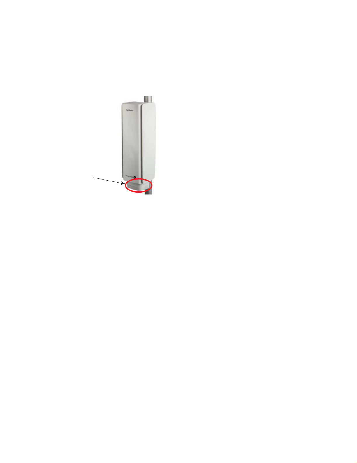
Product overview Supported installation options
....................................................................................................................................................................................................................................
RAFT
D
In addition, Alcatel-Lucent 9764 MCO LTE 2x1W and Alcatel-Lucent 9764 MCO LTE
2x2W products can be fitted with an optional 9764 MCO Wi-Fi AP module as shown in
the following figure.
Figure 2-6 9764 MCO Wi-Fi AP module attached to 9764 MCO LTE module (front
view)
Wi-Fi AP
Ethernet daisy chain installation options
In a daisy chain installation configuration two Alcatel-Lucent 9764 MCOs can be daisy
chained together, where they share the same backhaul port, thus reducing the investment
cost needed to connect the 9764 MCOs to the backhaul network and aggregating the
uplink and downlink traffic. Daisy chained 9764 MCOs may be co-located or separated
by some distance.
....................................................................................................................................................................................................................................
2-14
RAFT
D
Proprietary – Use pursuant to Company instruction
Alcatel-Lucent – Internal
Alcatel-Lucent 9764 MCO
3MN-01707-0002-RJZZA
Issue 3.05 October 2014
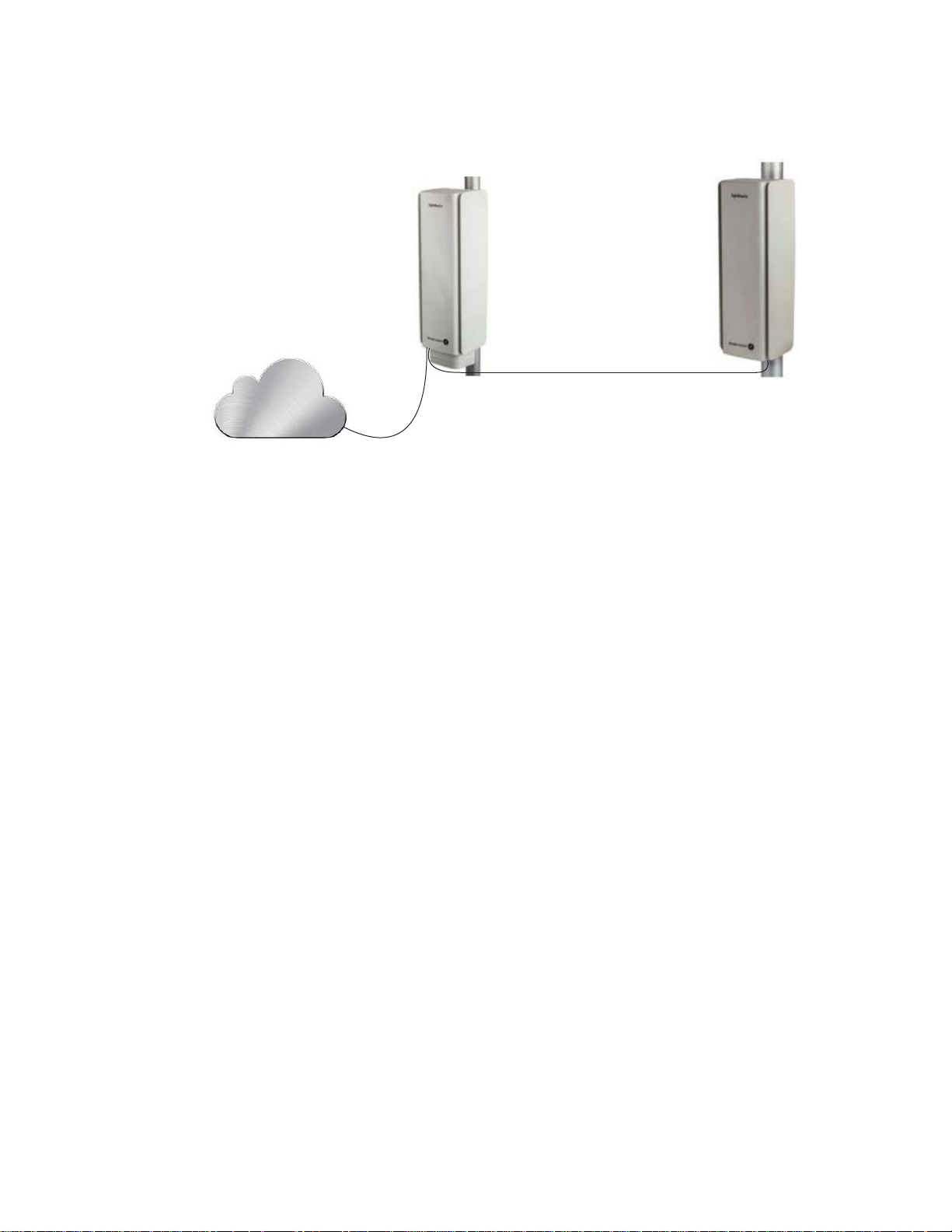
Product overview Supported installation options
....................................................................................................................................................................................................................................
Figure 2-7 9764 MCO daisy chain installation example
Backhaul
D
RAFT
Daisy chain configuration options are described in, “Pair mount and daisy chain
requirements” (p. 3-13)
Pair-mount installation options
In a “pair-mount” installation configuration a 9764 MCO LTE 2x1W product or a 9764
MCO LTE 2x2W product can be mounted with a 9764 MCO WCDMA product to form a
Multi-Standard Pair configuration. The supported pair-mount configurations are as
follows:
• A 9764 MCO V1.1 B2 LTE 2x1W in a pair-mount configuration with a 9764 MCO
V1.0 B2 WCDMA 1W.
• A 9764 MCO V1.1 B2/B25 LTE 2x1W in a pair-mount configuration with a 9764
MCO V1.0 B2 WCDMA 1W.
• A 9764 MCO V1.1 B2 LTE 2x2W in a pair-mount configuration with a 9764 MCO
V1.0 B2 WCDMA 1W,
• A 9764 MCO V1.1 B7 LTE 2x1W in a pair-mount configuration with a 9764 MCO
V1.0 B1 WCDMA 1W.
Note: This 9764 MCO V1.1 B7 LTE 2x1W/9764 MCO V1.0 B1 WCDMA 1W
pair-mount configuration applies to AC variants only.
Service providers can deploy these configurations on the same site to meet the growing
demands of capacity on the 3G and 4G technologies.
....................................................................................................................................................................................................................................
Alcatel-Lucent 9764 MCO
3MN-01707-0002-RJZZA
Issue 3.05 October 2014
Proprietary – Use pursuant to Company instruction
Alcatel-Lucent – Internal
2-15
D
RAFT
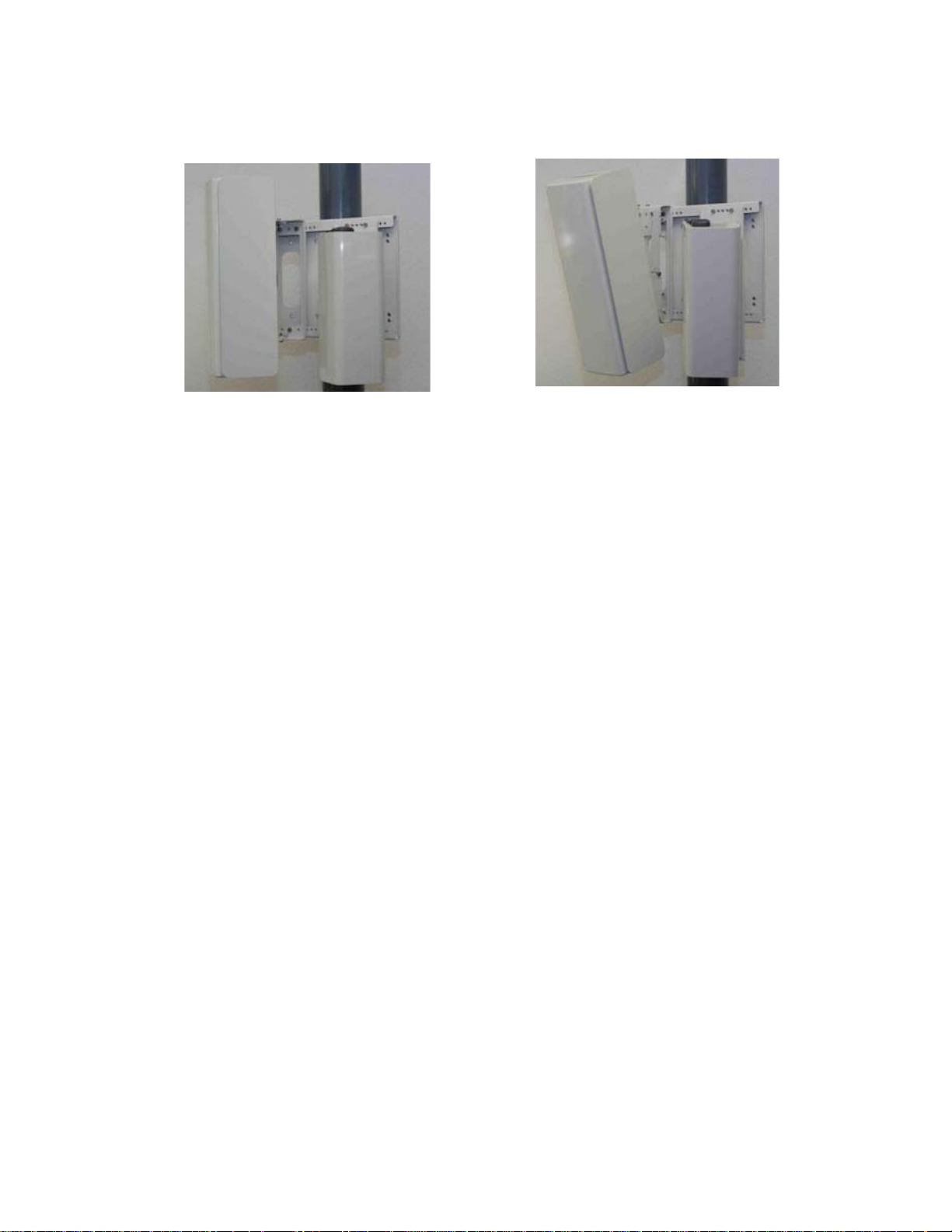
Product overview Supported installation options
....................................................................................................................................................................................................................................
RAFT
D
Figure 2-8 9764 MCO pair-mount installation example
pair-mount configuration options are described in, “Pair mount and daisy chain
requirements” (p. 3-13)
....................................................................................................................................................................................................................................
2-16
RAFT
D
Proprietary – Use pursuant to Company instruction
Alcatel-Lucent – Internal
Alcatel-Lucent 9764 MCO
3MN-01707-0002-RJZZA
Issue 3.05 October 2014

Product overview Hardware and ancillary items
....................................................................................................................................................................................................................................
Hardware and ancillary items
Overview
The following section lists the Alcatel-Lucent 9764 Metro Cell Outdoor base hardware
equipment, the installation kits and ancillary items that can be ordered from
Alcatel-Lucent.
9764 MCO base items
The Alcatel-Lucent 9764 MCO LTE 2x1W or the Alcatel-Lucent 9764 MCO LTE 2x2W
packaging contains the following base items:
• 9764 MCO LTE 2x1W module or
• 9764 MCO LTE 2x2W module
9764 Metro Dock base items
The Alcatel-Lucent 9764 Metro Dock packaging contains the following base items:
D
RAFT
• Alcatel-Lucent 9764 Metro Dock (including lock and key)
9764 MCO Wi-Fi AP base items
The Alcatel-Lucent 9764 Metro Cell Outdoor Wi-Fi AP is an optional product. Two
models are available:
• 9764 MCO Wi-Fi AP v1.0 MG model (medium-gain antenna)
• 9764 MCO Wi-Fi AP v1.0 HG model (high-gain antenna)
Ancillary items
The following tables list the ancillary items that are available for order from
Alcatel-Lucent in support of the defined equipment installation and configuration options.
Installation kits
The following table list the installation kits that are available for order from
Alcatel-Lucent in support of the equipment installation options.
Installation kit Description Use
Banding kit Stainless steel bands
Banding tool Standard BAND-IT
Band buckles (Ear-Lokt)
®
(CR00169), including operating
instructions
Banding Tool
Mandatory:
• pole mount only
Mandatory:
• use with the Banding kit for pole
mount only
Wall spacer kit 9764 Metro Dock wall spacer Mandatory:
• wall mount without tilt
....................................................................................................................................................................................................................................
Alcatel-Lucent 9764 MCO
3MN-01707-0002-RJZZA
Issue 3.05 October 2014
Proprietary – Use pursuant to Company instruction
Alcatel-Lucent – Internal
2-17
D
RAFT

Product overview Hardware and ancillary items
....................................................................................................................................................................................................................................
RAFT
D
Installation kit Description Use
Vertical tilt installation kit Vertical tilt bracket Mandatory:
• pole mount with tilt
• wall mount: with vertical only
• wall mount: with vertical and
horizontal tilt
Horizontal tilt installation kit Horizontal tilt bracket Mandatory:
• wall mount: with horizontal tilt only
• wall mount: with horizontal and
vertical tilt
Power
Item Description Use
Power connector (AC) AC power connector Required for 9764 MCO module with AC
Power connector (DC) DC power connector Required for 9764 MCO module with DC
Power cable Power cable IN/OUT 3G1,5mm²,
100m roll or multiples of 1m length
(as needed)
power (International markets)
power (International markets)
Required for 9764 MCO module
(International markets)
Power cable (AC) Power cable pre-assembled with AC
power connector, various lengths
(2m. 4.5m, 9m, 12m)
Power cable (DC) Power cable pre-assembled with DC
power connector, various lengths
(2m. 4.5m, 9m, 12m)
Required for 9764 MCO module with AC
power (North America Regional markets)
Required for 9764 MCO module with DC
power (North America Regional markets)
Grounding
Item Description Use
Ground cable Ground cable,Y/G 10mm² in 100m
roll
Ground cable Ground cable, 8 AWG Required for North America Regional
Required for International markets
markets
SFP modules
Item Description Use
SFP module SFP GBE 10/100/1000BaseT (copper) Optional
Electrical backhaul only
SFP module SFP GBE 1000BaseLX (Single mode) Optional
Optical backhaul, Daisy chaining
....................................................................................................................................................................................................................................
2-18
RAFT
D
Proprietary – Use pursuant to Company instruction
Alcatel-Lucent – Internal
Alcatel-Lucent 9764 MCO
3MN-01707-0002-RJZZA
Issue 3.05 October 2014

Product overview Hardware and ancillary items
....................................................................................................................................................................................................................................
Item Description Use
SFP module SFP GBE 1000BaseLX / CPRI (Single mode) Optional
Optical backhaul, Daisy chaining,
Pair-mount configuration
SFP module SFP GBE 1000BaseSX / CPRI (Multi mode) Optional
Optical backhaul, Daisy chaining,
Pair-mount configuration
Surge arrestor
Item Description Use
Internal surge arrestor
1
9764 Metro Dock internal Ethernet
surge arrestor kit
Optional
Highly recommended if GBE 1000BaseT
backhaul connection is provided
D
RAFT
External surge arrestor External Ethernet surge arrestor kit,
including:
• mounting bracket
• pole bands and buckle
• Ethernet cable, 0.6 m (2 ft)
Optional
Highly recommended if GBE 1000BaseT
backhaul connection is provided
Notes:
1. The 9764 Metro Dock internal Ethernet surge arrestor is available within Release LR14.1.L.
Ethernet cable - Electrical
Item Description Use
Electrical Ethernet cable 2 meter outdoor, 4 pairs, 2 RJ45 (plus
1 spare)
Electrical Ethernet cable 25 meter outdoor, 4 pairs, 2 RJ45
(plus 1 spare)
Electrical Ethernet cable 100 meter outdoor, 4 pairs, 2 RJ45
(plus 1 spare)
Optional
Use with SFP GBE 10/100/1000BaseT
Optional
Use with SFP GBE 10/100/1000BaseT
Optional
Use with SFP GBE 10/100/1000BaseT
Ethernet cable - Optical
Item Description Use
Fiber Optic cable SMDF LC-LC 2SM 5m
Single mode fiber duplex 250 mm
Breakout on both sides
Fiber Optic cable SMDF LC-LC 2SM 15m
Single mode fiber duplex 250 mm
Breakout on both sides
....................................................................................................................................................................................................................................
Alcatel-Lucent 9764 MCO
3MN-01707-0002-RJZZA
Issue 3.05 October 2014
Proprietary – Use pursuant to Company instruction
Alcatel-Lucent – Internal
Optional
Use with SFP GBE 1000BaseLX (Single
mode)
Optional
Use with SFP GBE 1000BaseLX (Single
mode)
2-19
D
RAFT

Product overview Hardware and ancillary items
....................................................................................................................................................................................................................................
RAFT
D
Item Description Use
Fiber Optic cable SMDF LC-LC 2SM 30m
Single mode fiber duplex 250 mm
Breakout on both sides
Fiber Optic cable SMDF LC-LC 2SM 50m
Single mode fiber duplex 250 mm
Breakout on both sides
Fiber Optic cable SMDF LC-LC 2SM 70m
Single mode fiber duplex 250 mm
Breakout on both sides
Fiber Optic cable SMDF LC-LC 2SM 85m
Single mode fiber duplex 250 mm
Breakout on both sides
Fiber Optic cable SMDF LC-LC 2SM 100m
Single mode fiber duplex 250 mm
Breakout on both sides
Fiber Optic cable SMDF LC-LC 2SM 150m
Single mode fiber duplex 250 mm
Breakout on both sides
Fiber Optic cable SMDF LC-LC 2SM 200m
Single mode fiber duplex 250 mm
Breakout on both sides
Optional
Use with SFP GBE 1000BaseLX (Single
mode)
Optional
Use with SFP GBE 1000BaseLX (Single
mode)
Optional
Use with SFP GBE 1000BaseLX (Single
mode)
Optional
Use with SFP GBE 1000BaseLX (Single
mode)
Optional
Use with SFP GBE 1000BaseLX (Single
mode)
Optional
Use with SFP GBE 1000BaseLX (Single
mode)
Optional
Use with SFP GBE 1000BaseLX (Single
mode)
Fiber Optic cable SMDF LC-LC 2SM 250m
Single mode fiber duplex 250 mm
Breakout on both sides
Fiber Optic cable SMDF LC-LC 2SM 300m
Single mode fiber duplex 250 mm
Breakout on both sides
Fiber Optic cable MM LC-LC 2MM 5m
Multi mode fiber duplex, 250 mm
Breakout on both sides
Fiber Optic cable MM LC-LC 2MM 15m
Multi mode fiber duplex, 250 mm
Breakout on both sides
Fiber Optic cable MM LC-LC 2MM 30m
Multi mode fiber duplex, 250 mm
Breakout on both sides
Fiber Optic cable MM LC-LC 2MM 50m
Multi mode fiber duplex, 250 mm
Breakout on both sides
Fiber Optic cable MM LC-LC 2MM 70m
Multi mode fiber duplex, 250 mm
Breakout on both sides
Optional
Use with SFP GBE 1000BaseLX (Single
mode)
Optional
Use with SFP GBE 1000BaseLX (Single
mode)
Optional
SFP GBE 1000BaseSX (Multi mode)
Optional
SFP GBE 1000BaseSX (Multi mode)
Optional
SFP GBE 1000BaseSX (Multi mode)
Optional
SFP GBE 1000BaseSX (Multi mode)
Optional
SFP GBE 1000BaseSX (Multi mode)
....................................................................................................................................................................................................................................
2-20
RAFT
D
Proprietary – Use pursuant to Company instruction
Alcatel-Lucent – Internal
Alcatel-Lucent 9764 MCO
3MN-01707-0002-RJZZA
Issue 3.05 October 2014

Product overview Hardware and ancillary items
....................................................................................................................................................................................................................................
Item Description Use
D
RAFT
Fiber Optic cable MM LC-LC 2MM 85m
Multi mode fiber duplex, 250 mm
Breakout on both sides
Fiber Optic cable MM LC-LC 2MM 100m
Multi mode fiber duplex, 250 mm
Breakout on both sides
Fiber Optic cable MM LC-LC 2MM 150m
Multi mode fiber duplex, 250 mm
Breakout on both sides
Fiber Optic cable MM LC-LC 2MM 200m
Multi mode fiber duplex, 250 mm
Breakout on both sides
Fiber Optic cable MM LC-LC 2MM 250m
Multi mode fiber duplex, 250 mm
Breakout on both sides
Fiber Optic cable MM LC-LC 2MM 300m
Multi mode fiber duplex, 250 mm
Breakout on both sides
External antenna - GPS
Optional
SFP GBE 1000BaseSX (Multi mode)
Optional
SFP GBE 1000BaseSX (Multi mode)
Optional
SFP GBE 1000BaseSX (Multi mode)
Optional
SFP GBE 1000BaseSX (Multi mode)
Optional
SFP GBE 1000BaseSX (Multi mode)
Optional
SFP GBE 1000BaseSX (Multi mode)
Item Description Use
GPS antenna External GPS Antenna, 1575
MHz*26 dBi
GPS antenna External GPS Antenna, 1575
MHz*40 dBi
Jumper cable External GPS Antenna jumper cable
(various lengths)
Adapter cable External GPS Antenna adaptor cable
from the ancillary
Weatherproof tape For B25 MCO, B2 MCO and B2/B25
MCO - one layer of weatherproof
tape applied to the cable connections.
For B3 MCO and B7 MCO, the
following two types of weatherproof
tape must be applied to the cable
connections: first the linerless rubber
splicing tape and then the vinyl
electrical tape (vinyl tape over rubber
tape).
Used if MCO is configured for external
GPS antenna and cable loss <10dBi @
1575MHz
Used if MCO is configured for external
GPS antenna and cable loss >10dBi @
1575MHz
Mandatory
1 cable per MCO if external GPS antenna
is used
Mandatory
1 cable per MCO if external GPS antenna
is used
Mandatory
....................................................................................................................................................................................................................................
Alcatel-Lucent 9764 MCO
3MN-01707-0002-RJZZA
Issue 3.05 October 2014
Proprietary – Use pursuant to Company instruction
Alcatel-Lucent – Internal
2-21
D
RAFT

Product overview Hardware and ancillary items
....................................................................................................................................................................................................................................
RAFT
D
Note: The internal GPS antenna solution is not supported on the 9764 MCO V1.1 B7
LTE 2x1W, 9764 MCO V1.1 B2 LTE 2x1W and 9764 MCO V1.0 B25 LTE 2x1W
models.
External RF antennas
The 9764 MCO V1.1 B2 LTE 2x2W module has two external RF antenna ports for the
connection to third party supplied antennas.
For the RF antenna specifications refer to the RF antenna part of the System architecture
section of the 9YZ-04152-0056-DEZZA - Alcatel-Lucent 9764 Metro Cell Outdoor LTE
2x1W and 2x2W Technical Description document.
Pair-mount configuration
Item Description Use
9764 Metro Dock double
support plate
Extension plate Alignment Plate for 3G 9764 MCO in
Support plate for mounting 9764
MCO in a pair-mount configuration
a pair-mount configuration
Use in a 9764 MCO pair-mount
configuration
Use in a 9764 MCO pair-mount
configuration
....................................................................................................................................................................................................................................
2-22
RAFT
D
Proprietary – Use pursuant to Company instruction
Alcatel-Lucent – Internal
Alcatel-Lucent 9764 MCO
3MN-01707-0002-RJZZA
Issue 3.05 October 2014

3 3Installation of the 9764
Metro Dock
Overview
Purpose
This chapter provides the information and procedures for mounting the 9764 Metro Dock
onto a pole or wall, with or without the optional tilt mechanism.
D
RAFT
Contents
9764 Metro Dock pre-installation 3-2
9764 Metro Dock Pre-installation information 3-3
Pole mount installation requirements 3-5
Wall mount installation requirements 3-9
Pair mount and daisy chain requirements 3-13
9764 Metro Dock installation 3-18
Procedure 3-1: Pole mount the 9764 Metro Dock 3-19
Procedure 3-2: Pole mount the 9764 Metro Dock using optional tilt brackets 3-25
Procedure 3-3: Wall mount the 9764 Metro Dock 3-35
Procedure 3-4: Wall mount the 9764 Metro Dock using optional tilt brackets 3-40
Procedure 3-5: Pole mount the 9764 Metro Dock in a pair configuration 3-54
Procedure 3-6: Wall mount the 9764 Metro Dock in a pair configuration 3-71
9764 Metro Dock cabling 3-89
Procedure 3-7: 9764 Metro Dock ground cabling 3-90
Procedure 3-8: 9764 Metro Dock Ethernet cabling - fiber optic 3-92
Procedure 3-9: 9764 Metro Dock Ethernet cabling - electrical 3-99
9764 Metro Dock post-installation 3-111
Procedure 3-10: Final installation activities and checks 3-112
...................................................................................................................................................................................................................................
Alcatel-Lucent 9764 MCO
3MN-01707-0002-RJZZA
Issue 3.05 October 2014
Proprietary – Use pursuant to Company instruction
Alcatel-Lucent – Internal
3-1
D
RAFT

Installation of the 9764 Metro Dock
9764 Metro Dock pre-installation
....................................................................................................................................................................................................................................
RAFT
9764 Metro Dock pre-installation
Overview
D
Overview
Purpose
This section provides pre-installation information as well as listing tools and materials
required for Alcatel-Lucent 9764 Metro Dock mounting.
Contents
9764 Metro Dock Pre-installation information 3-3
Pole mount installation requirements 3-5
Wall mount installation requirements 3-9
Pair mount and daisy chain requirements 3-13
....................................................................................................................................................................................................................................
3-2
RAFT
D
Proprietary – Use pursuant to Company instruction
Alcatel-Lucent – Internal
Alcatel-Lucent 9764 MCO
3MN-01707-0002-RJZZA
Issue 3.05 October 2014

Installation of the 9764 Metro Dock
9764 Metro Dock pre-installation
....................................................................................................................................................................................................................................
9764 Metro Dock Pre-installation information
9764 Metro Dock Pre-installation information
Verify site preparation
The following site preparation requirements should be checked and met before the
installation of the equipment can begin. If some of the requirements are not met, the
installer must do so now:
• Ensure equipment is planned to be installed as high as possible to avoid obstructions
• Consider nearby sources of interference. Also check possibility of future obstructions
such as plans to erect buildings and trees that may grow tall enough to obstruct the
wireless path
• Ensure adequate clearance is provided for service access
• Ground, power and backhaul cabling has been routed and is in place
• Ensure any site specific fixing materials (screws, washers, wall plugs) for pole/wall
mounting the equipment are available.
D
RAFT
Product delivery contents
Unpack and examine the product packaging contents. If you notice any damage, or
missing items as listed in the Packing List, immediately notify the carrier that delivered
the unit and contact your Alcatel-Lucent representative.
The Alcatel-Lucent 9764 Metro Dock product packaging contains the following items:
• The 9764 Metro Dock module (including lock and key)
Installation kits
In addition to the standard product deliverable ensure the appropriate installation kits and
ancillary items are available to support the product mounting options.
Installation Kits Pole mount Wall mount
Banding kit Yes Yes
Banding tool Yes Yes
Vertical tilt kit Yes Yes Yes
Horizontal tilt kit Yes Yes
No tilt With tilt No tilt Vertical tilt
only
Horizontal
tilt only
Combined
horiz./vert. tilt
Wall spacer kit Yes
Basic kit Yes Yes Yes Yes Yes Yes
....................................................................................................................................................................................................................................
Alcatel-Lucent 9764 MCO
3MN-01707-0002-RJZZA
Issue 3.05 October 2014
Proprietary – Use pursuant to Company instruction
Alcatel-Lucent – Internal
3-3
D
RAFT

Installation of the 9764 Metro Dock
9764 Metro Dock pre-installation
....................................................................................................................................................................................................................................
Tools required for installation
RAFT
D
The following tools may be used during installation:
9764 Metro Dock Pre-installation information
• Drill (pneumatic hammer) and assorted drill bits
• Pliers
• Adjustable spanners
• M17 socket wrench
• Screwdrivers (power and/or manual):
– Phillips (flat blade)
– Torx (T-25 and T-40)
• HRS (Hirose) HT206/TM21p-88p crimping tool (for RJ45 cable)
• Data cable tester for shielded RJ45 (optional)
• Measuring tape
• Digital compass (to aid establishing product orientation)
• Marker, to mark wall mounting holes
• Vacuum cleaner or equivalent (required for clearing debris from wall mounting holes)
• Spirit level
• Hammer
• PIB (self-amalgamating) tape and 3M Super 33+ vinyl tape
• Ear protectors and safety goggles/glasses
• Assorted cable ties (various lengths)
• Heavy duty tape
• Adjustable straps
....................................................................................................................................................................................................................................
3-4
RAFT
D
Proprietary – Use pursuant to Company instruction
Alcatel-Lucent – Internal
Alcatel-Lucent 9764 MCO
3MN-01707-0002-RJZZA
Issue 3.05 October 2014

Installation of the 9764 Metro Dock
9764 Metro Dock pre-installation
....................................................................................................................................................................................................................................
Pole mount installation requirements
Pole mount installation requirements
Purpose
This topic outlines the basic requirements, installation kits and recommended anchor
materials when mounting the Alcatel-Lucent 9764 Metro Dock directly onto a pole, onto
tilt brackets or onto a pair-mount bracket.
Pole mount options
The 9764 Metro Dock is less than 1 kg (2.2 lbs) and can be easily mounted onto a pole
(wooden or metal) for the following installation options:
• 9764 Metro Dock screwed onto a wooden pole (without the tilt option).
Mounting screws and washers have to be locally supplied. Two M8x50 stainless steel
hex head screws and two M8x16x1.6 plain washers are recommended.
• 9764 Metro Dock banded onto a wooden or metal pole (without the tilt option)
The pole band installation kit is used.
D
RAFT
• 9764 Metro Dock attached to the vertical tilt bracket. Vertical tilt bracket is either
screwed or banded onto a wooden or metal pole.
• 9764 Metro Dock pair (with or without tilt brackets) attached to a double Metro Dock
support plate. Double Metro Dock support plate is banded onto a wooden or metal
pole.
This deployment option is used when a 9764 MCO V1.1 LTE 2x1W or a 9764 MCO
LTE 2x2W product is mounted with a 9764 MCO WCDMA 1W product to form a
Multi-Standard Pair configuration.
The available pair-mount installation options are:
– a 9764 MCO V1.1 B2 LTE 2x1W product mounted with a 9764 MCO V1.0 B2
WCDMA 1W product
– a 9764 MCO V1.1 B2/B25 LTE 2x1W product with a 9764 MCO V1.0 B2
WCDMA 1W product
– a 9764 MCO V1.1 B7 LTE 2x1W product mounted with a 9764 MCO V1.0 B1
WCDMA 1W product
– a 9764 MCO V1.1 B2 LTE 2x2W product mounted with a 9764 MCO V1.0 B1
WCDMA 1W product.
....................................................................................................................................................................................................................................
Alcatel-Lucent 9764 MCO
3MN-01707-0002-RJZZA
Issue 3.05 October 2014
Proprietary – Use pursuant to Company instruction
Alcatel-Lucent – Internal
3-5
D
RAFT

Installation of the 9764 Metro Dock
9764 Metro Dock pre-installation
....................................................................................................................................................................................................................................
Pole mount installation kits and brackets
RAFT
D
The following table provides the orderable installation kits and brackets that can be used,
Pole mount installation requirements
depending on the deployment scenario, for 9764 Metro Dock pole mounting.
Table 3-1 Pole mount installation kits and brackets
Item Description
Banding kit Required when directly attaching the 9764 Metro Dock or vertical tilt
Banding tool Standard BAND-IT
Vertical tilt bracket Provides +/- 30° vertical tilt (up/down) adjustment
Double 9764 MCO support plate Double 9764 MCO support plate for pair-mount deployment option
Double 9764 MCO extension plate Extension plate for 3G 9764 MCO and 4G 9764 MCO alignment in a
bracket to a pole (diameter 50 to 300 mm) using stainless steel bands.
Stainless steel bands and buckles (Ear-Lokt)
®
instructions
Required in order to tighten stainless steel metal bands
pair-mount deployment option
Banding Tool (CR00169), including operating
1
Notes:
1. Due to the length of the 9764 MCO LTE module, thermal limitations dictate maximum
adjustment of +/- 20° vertical tilt.
The following figure shows the orderable brackets used for pole mount installation,
depending on the deployment scenario.
Figure 3-1 Pole mount banding and brackets
Tilt bracket assembly
(single Metro Dock)
....................................................................................................................................................................................................................................
3-6
RAFT
Proprietary – Use pursuant to Company instruction
Alcatel-Lucent – Internal
D
Tilt bracket assembly
(double Metro Dock)
Alcatel-Lucent 9764 MCO
3MN-01707-0002-RJZZA
Issue 3.05 October 2014
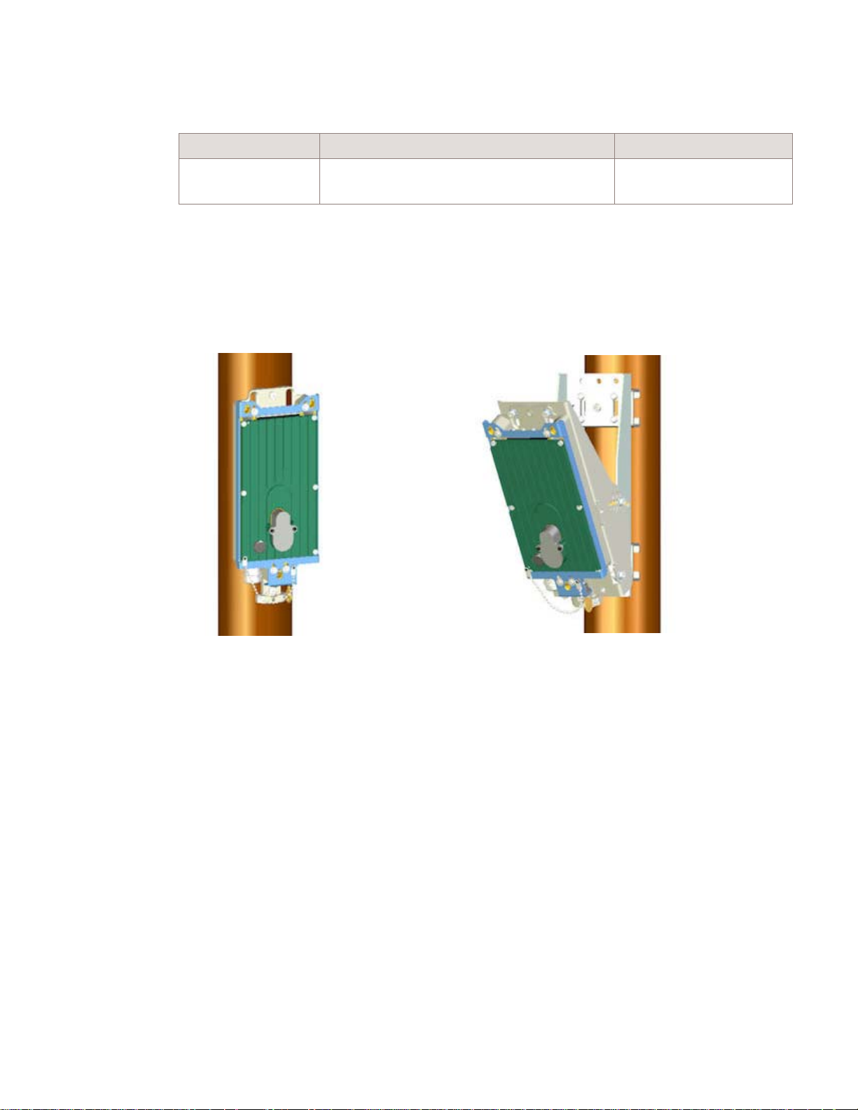
Installation of the 9764 Metro Dock
9764 Metro Dock pre-installation
....................................................................................................................................................................................................................................
Pole mount installation requirements
Recommended pole anchor materials
Surface structure Recommended anchor materials Recommended screw torque
D
RAFT
Wood Screw Hex T M8x50 stainless steel (x2)
Pole mount installation examples
The following figures show examples of 9764 Metro Dock pole mount installation, pole
mount installation using vertical tilt and pair-mount installation.
Figure 3-2 9764 Metro Dock pole mount using screws
7.0 N.m (62.0 lb.in).
Washer plain M8x16x1.6 stainless steel (x2)
Pole mount - without tilt
....................................................................................................................................................................................................................................
Alcatel-Lucent 9764 MCO
3MN-01707-0002-RJZZA
Issue 3.05 October 2014
Proprietary – Use pursuant to Company instruction
Alcatel-Lucent – Internal
Pole mount - with tilt
3-7
D
RAFT
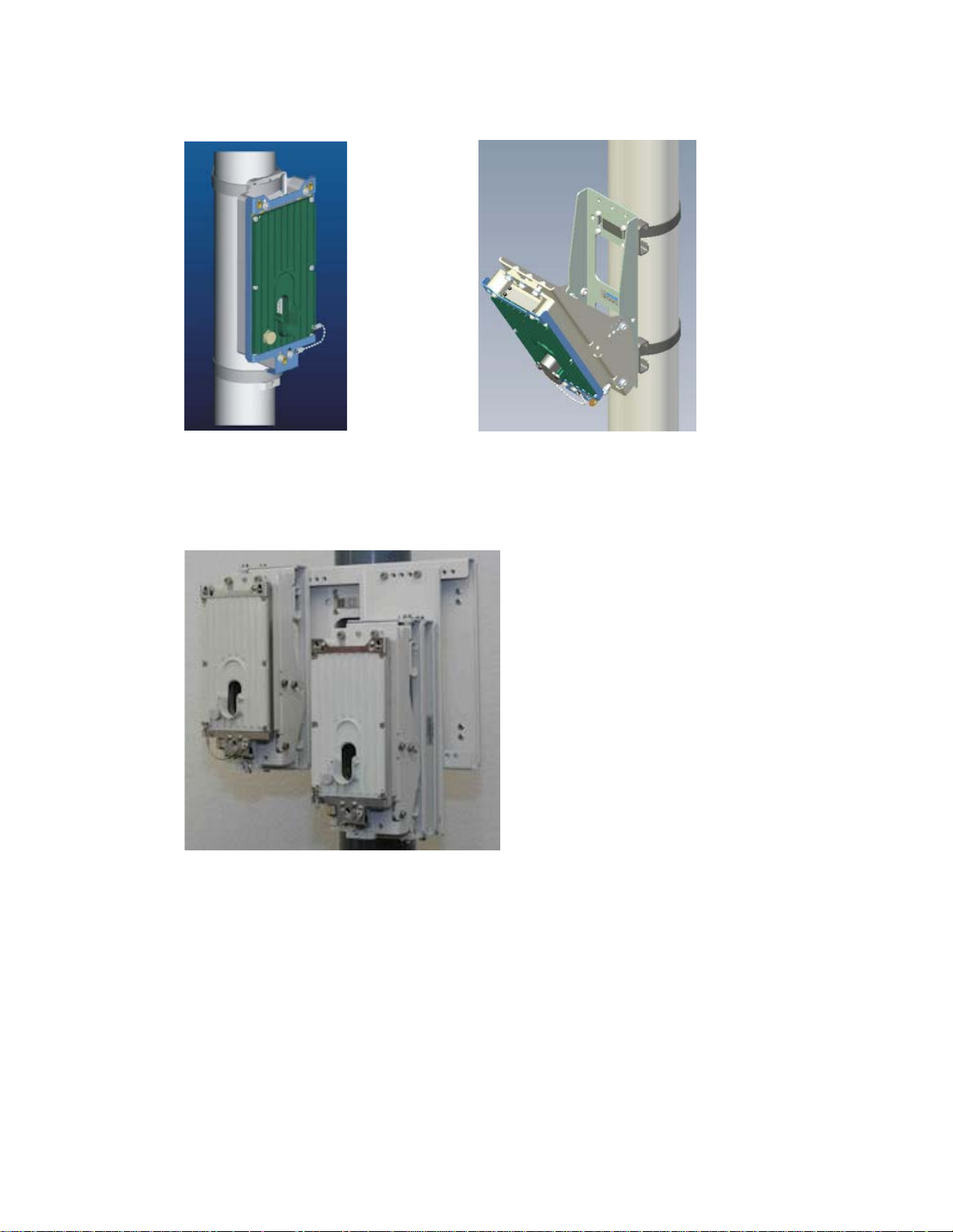
Installation of the 9764 Metro Dock
9764 Metro Dock pre-installation
....................................................................................................................................................................................................................................
RAFT
Figure 3-3 9764 Metro Dock pole mount using banding
Pole mount installation requirements
D
Pole mount - without tilt
Pole mount - with tilt
Figure 3-4 Double 9764 Metro Dock pole mount
....................................................................................................................................................................................................................................
3-8
RAFT
D
Proprietary – Use pursuant to Company instruction
Alcatel-Lucent – Internal
Alcatel-Lucent 9764 MCO
3MN-01707-0002-RJZZA
Issue 3.05 October 2014

Installation of the 9764 Metro Dock
9764 Metro Dock pre-installation
....................................................................................................................................................................................................................................
Wall mount installation requirements
Wall mount installation requirements
Purpose
This topic outlines basic requirements, installation kits and recommended anchor
materials when mounting the Alcatel-Lucent 9764 Metro Dock onto a solid concrete wall
or flat surface, onto tilt brackets or onto a pair-mount bracket.
Wall mount options
The 9764 Metro Dock weighs less than 1 kg (2.2 lbs) and can be easily mounted onto any
flat, sturdy wall for the following installation options:
• 9764 Metro Dock attached to directly to a wall or flat surface (using wall spacer)
• 9764 Metro Dock attached to the vertical/horizontal tilt bracket(s). Vertical/horizontal
tilt bracket(s) are attached to a wall.
• 9764 Metro Dock pair (with or without tilt brackets) attached to a double Metro Dock
support plate. Double Metro Dock support plate is attached to a wall.
D
RAFT
This deployment option is used when a 9764 MCO V1.1 LTE 2x1W product or a
9764 MCO LTE 2x2Wproduct is mounted with a 9764 MCO WCDMA 1W product to
form a Multi-Standard Pair configuration.
The available pair-mount installation options are: a 9764 MCO V1.1 B2 LTE 2x1W
product mounted with a 9764 MCO V1.0 B2 WCDMA 1W, a 9764 MCO V1.1 B7
LTE 2x1W product mounted with a 9764 MCO V1.0 B1 WCDMA 1W product and a
9764 MCO V1.1 B2 LTE 2x2W product mounted with a 9764 MCO V1.0 B1
WCDMA 1W product.
Wall mount installation brackets and kits
The following table lists the orderable installation brackets that can be used, depending on
the deployment scenario, for 9764 Metro Dock wall mounting.
Table 3-2 Wall mount installation brackets
Item Description
Wall spacer Required when directly attaching the 9764 Metro Dock to a wall or flat
Vertical tilt bracket
....................................................................................................................................................................................................................................
Alcatel-Lucent 9764 MCO
3MN-01707-0002-RJZZA
Issue 3.05 October 2014
1
Proprietary – Use pursuant to Company instruction
surface and no tilt device is used. The wall spacer keeps a sufficient
distance between the wall and 9764 Metro Dock for airflow purposes.
Note: If vertical/horizontal tilt device is used, then the wall spacer is not
required.
Provides +/- 30° vertical tilt (up/down) adjustment
Note: Can be used in combination with the horizontal installation kit to
provide:
• +/- 30° vertical tilt (up/down) adjustment, and
• +/-45° horizontal tilt (left/right) adjustment
Alcatel-Lucent – Internal
3-9
D
RAFT

Installation of the 9764 Metro Dock
9764 Metro Dock pre-installation
....................................................................................................................................................................................................................................
RAFT
Table 3-2 Wall mount installation brackets (continued)
Wall mount installation requirements
D
Item Description
Horizontal tilt bracket Provides +/-45° horizontal tilt (left/right) adjustment
Note: Can be used in combination with the vertical tilt installation kit to
provide:
• +-45° horizontal tilt (left/right) adjustment, and
• +/- 30° vertical tilt (up/down) adjustment
Double 9764 MCO support plate Double 9764 MCO support plate for pair-mount deployment option
Double 9764 MCO extension plate Extension plate for 3G 9764 MCO and 4G 9764 MCO alignment in a
pair-mount deployment option
Notes:
1. Due to the length of the 9764 MCO LTE module, thermal limitations dictate maximum
adjustment of +/- 20° vertical tilt.
The following figure shows the orderable brackets used for wall mount installation,
depending on the deployment scenario.
Figure 3-5 Wall mount brackets
Spacer bracket
(wall only)
Horizontal tilt bracket
(wall only)
Vertical tilt bracket
(wall/pole)
Recommended wall anchor materials
Surface structure Recommended anchor materials Recommended screw torque
Wood Screw Hex T M8x70 stainless steel (x3)
Washer plain M8x16x1.6 stainless steel (x3)
Concrete Screw CHC M6x80 stainless steel (x3)
Washer plain M6x12x1.6mm stainless steel (x3)
Washer spring M6x12x1.2mm stainless steel (x3)
Plug expansion Rawlnut M6x50 (x3)
....................................................................................................................................................................................................................................
3-10
RAFT
Proprietary – Use pursuant to Company instruction
Alcatel-Lucent – Internal
D
7.0 N.m (62.0 lb.in).
7.0 N.m (62.0 lb.in).
Alcatel-Lucent 9764 MCO
3MN-01707-0002-RJZZA
Issue 3.05 October 2014

Installation of the 9764 Metro Dock
9764 Metro Dock pre-installation
....................................................................................................................................................................................................................................
Wall mount installation requirements
Wall mount installation examples
The following figures show examples of 9764 Metro Dock wall mount installation, wall
mount installation using horizontal/vertical tilt and pair-mount installation.
Figure 3-6 9764 Metro Dock wall mount (no tilt)
D
RAFT
Figure 3-7 9764 Metro Dock wall mount (with tilt)
Vertical tilt only
Horizontal tilt only
Horizontal/Vertical tilt
combination
....................................................................................................................................................................................................................................
Alcatel-Lucent 9764 MCO
3MN-01707-0002-RJZZA
Issue 3.05 October 2014
Proprietary – Use pursuant to Company instruction
Alcatel-Lucent – Internal
3-11
D
RAFT

Installation of the 9764 Metro Dock
9764 Metro Dock pre-installation
....................................................................................................................................................................................................................................
RAFT
Figure 3-8 Double 9764 Metro Dock wall mount
Wall mount installation requirements
D
....................................................................................................................................................................................................................................
3-12
RAFT
D
Proprietary – Use pursuant to Company instruction
Alcatel-Lucent – Internal
Alcatel-Lucent 9764 MCO
3MN-01707-0002-RJZZA
Issue 3.05 October 2014

Installation of the 9764 Metro Dock
9764 Metro Dock pre-installation
....................................................................................................................................................................................................................................
Pair mount and daisy chain requirements
Pair mount and daisy chain requirements
Overview
Two 9764 MCOs can be daisy chained together to share the same backhaul port, reducing
the investment cost needed to connect the 9764 MCOs to the backhaul network and
aggregating the uplink traffic. Daisy chain connectivity scenarios support 9764 MCOs
that are co-located and connected together (for example, connectivity used for pair-mount
configurations) or 9764 MCOs that are separated by some distance.
Pair-mount configuration with daisy chaining
A 9764 MCO LTE connected to the backhaul network plus a 9764 MCO WCDMA
connected to the daisy chain port of the 9764 MCO LTE that is connected to the backhaul
network.
Pair-mount installation options that form a Multi-Standard Pair configuration are:
• a 9764 MCO V1.1 B2 LTE 2x1W product is pair-mounted with a 9764 MCO V1.0 B2
WCDMA 1W,
D
RAFT
• a 9764 MCO V1.1 B2/B25 LTE 2x1W product with a 9764 MCO V1.0 B2 WCDMA
1W product
• a 9764 MCO V1.1 B2 LTE 2x2W product is pair-mounted with a 9764 MCO V1.0 B2
WCDMA 1W,
• a 9764 MCO V1.1 B7 LTE 2x1W product is pair-mounted with a 9764 MCO V1.0 B1
WCDMA 1W product.
....................................................................................................................................................................................................................................
Alcatel-Lucent 9764 MCO
3MN-01707-0002-RJZZA
Issue 3.05 October 2014
Proprietary – Use pursuant to Company instruction
Alcatel-Lucent – Internal
3-13
D
RAFT

Installation of the 9764 Metro Dock
9764 Metro Dock pre-installation
....................................................................................................................................................................................................................................
Pair mount and daisy chain requirements
RAFT
D
Backhaul
Note:
Electrical SFP
or
Optical SFP
(SMorMM)
4G LTE MCO (2x1W)
BH1
Wi-Fi AP
Electrical cable
or
Optical 250 mm breakout
cable (SM or MM)
Metro Dock double support plate
Optical SFP
(SM or MM)
BH2
Optical 250 mm breakout
cable (SM or MM)
3G WCDMA MCO (1W)
BH1
BH2
• An optional Wi-Fi Access Point may be attached to the MCO that is connected to
the backhaul network.
• To support Carrier Aggregation or Carrier Aggregation readiness the optical daisy
chain SFPs should a Single Mode GBE/CPRI SFP or a Multi Mode GBE/CPRI
SFP.
Pair-mount configuration without daisy chaining
A 9764 MCO LTE connected to the backhaul network plus a 9764 MCO WCDMA
connected to the backhaul network, with no daisy chaining.
Pair-mount installation options that form a Multi-Standard Pair configuration are:
• a 9764 MCO V1.1 B2 LTE 2x1W product is pair-mounted with a 9764 MCO V1.0 B2
WCDMA 1W,
a 9764 MCO V1.1 B2/B25 LTE 2x1W product with a 9764 MCO V1.0 B2 WCDMA
1W product
• a 9764 MCO V1.1 B2 LTE 2x2W product is pair-mounted with a 9764 MCO V1.0 B2
WCDMA 1W,
• a 9764 MCO V1.1 B7 LTE 2x1W product is pair-mounted with a 9764 MCO V1.0 B1
WCDMA 1W product.
....................................................................................................................................................................................................................................
3-14
RAFT
D
Proprietary – Use pursuant to Company instruction
Alcatel-Lucent – Internal
Alcatel-Lucent 9764 MCO
3MN-01707-0002-RJZZA
Issue 3.05 October 2014

Installation of the 9764 Metro Dock
9764 Metro Dock pre-installation
....................................................................................................................................................................................................................................
Metro Dock double support plate
Pair mount and daisy chain requirements
D
RAFT
Electrical SFP
Optical SFP
(SMorMM)
Backhaul
or
Electrical cable
or
Optical 250 mm breakout
cable (SM or MM)
4G LTE MCO (2x1W)
BH1
Wi-Fi AP
BH2
Backhaul
Electrical SFP
or
Optical SFP
(SMorMM)
Optical 250 mm breakout
3G WCDMA MCO (1W)
Electrical cable
or
cable (SM or MM)
BH1
BH2
Note: An optional Wi-Fi Access Point may be attached to the MCO that is connected
to the backhaul network.
Daisy chaining without pair-mount configuration
A maximum of two 9764 MCO modules and a single Wi-Fi Access Point may be daisy
chained together.
The 9764 MCO LTE supports the following daisy chain configurations:
• A 9764 MCO LTE connected to the backhaul network plus a 9764 MCO LTE
connected to the daisy chain port of the 9764 MCO LTE that is connected to the
backhaul network.
....................................................................................................................................................................................................................................
Alcatel-Lucent 9764 MCO
3MN-01707-0002-RJZZA
Issue 3.05 October 2014
Proprietary – Use pursuant to Company instruction
Alcatel-Lucent – Internal
3-15
D
RAFT

Installation of the 9764 Metro Dock
Pair mount and daisy chain requirements
9764 Metro Dock pre-installation
....................................................................................................................................................................................................................................
RAFT
D
4G LTE MCO (2x1W)
4G LTE MCO (2x1W)
Optical SFP
(SMorMM)
Optical 250 mm breakout
cable (SM or MM)
BH1
BH2
Backhaul
Electrical SFP
or
Optical SFP
(SMorMM)
Electrical cable
Optical 250 mm breakout
cable (SM or MM)
or
Wi-Fi AP
BH1
BH2
• A 9764 MCO LTE connected to the backhaul network plus a 9764 MCO WCDMA
connected to the daisy chain port of the 9764 MCO LTE.
4G LTE MCO (2x1W)
3G WCDMA MCO (1W)
Electrical SFP
Optical SFP
(SMorMM)
Backhaul
or
Wi-Fi AP
Electrical cable
or
Optical 250 mm breakout
cable (SM or MM)
BH1
BH2
Optical SFP
(SMorMM)
Optical 250 mm breakout
cable (SM or MM)
BH1
BH2
....................................................................................................................................................................................................................................
3-16
RAFT
D
Proprietary – Use pursuant to Company instruction
Alcatel-Lucent – Internal
Alcatel-Lucent 9764 MCO
3MN-01707-0002-RJZZA
Issue 3.05 October 2014

Installation of the 9764 Metro Dock
9764 Metro Dock pre-installation
....................................................................................................................................................................................................................................
Pair mount and daisy chain requirements
If a 9764 MCO Wi-Fi AP module is to be included in the daisy chain configuration, the
following Wi-Fi AP configurations are supported:
• A 9764 MCO Wi-Fi AP module can be attached to each daisy chained 9764 MCO
when the daisy chained MCOs are installed in separate locations (e.g., not co-located
on the same pole).
• If the daisy chained MCOs are co-located, only one 9764 MCO Wi-Fi AP module can
be used and the 9764 MCO Wi-Fi AP module must be attached to the 9764 MCO LTE
that is connected to the backhaul network.
Note: An optional Wi-Fi Access Point may be attached to the MCO that is connected
to the backhaul network.
D
RAFT
....................................................................................................................................................................................................................................
Alcatel-Lucent 9764 MCO
3MN-01707-0002-RJZZA
Issue 3.05 October 2014
Proprietary – Use pursuant to Company instruction
Alcatel-Lucent – Internal
3-17
D
RAFT

Installation of the 9764 Metro Dock
9764 Metro Dock installation
....................................................................................................................................................................................................................................
RAFT
9764 Metro Dock installation
Overview
D
Overview
Purpose
This section provides the installation instructions for mounting the Alcatel-Lucent 9764
Metro Dock onto either a pole or wall with or without the optional tilt mechanism. The
section also provides the installation instructions for a pair-mount configuration. This
deployment option is used when a 9764 MCO V1.1 LTE 2x1W product or a 9764 MCO
V1.1 B2 LTE 2x2W product is mounted with a 9764 MCO WCDMA 1W product to form
a Multi-Standard Pair configuration.
The available pair-mount installation options are:
• a 9764 MCO V1.1 B2 LTE 2x1W product is mounted with a 9764 MCO V1.0 B2
WCDMA 1W product
Contents
• a 9764 MCO V1.1 B2/B25 LTE 2x1W product is mounted with a 9764 MCO V1.0 B2
WCDMA 1W product
• a 9764 MCO V1.1 B7 LTE 2x1W product is mounted with a 9764 MCO V1.0 B1
WCDMA 1W product.
• a 9764 MCO V1.1 B2 LTE 2x2W product is pair-mounted with a 9764 MCO V1.0 B2
WCDMA 1W,
Procedure 3-1: Pole mount the 9764 Metro Dock 3-19
Procedure 3-2: Pole mount the 9764 Metro Dock using optional tilt brackets 3-25
Procedure 3-3: Wall mount the 9764 Metro Dock 3-35
Procedure 3-4: Wall mount the 9764 Metro Dock using optional tilt brackets 3-40
Procedure 3-5: Pole mount the 9764 Metro Dock in a pair configuration 3-54
Procedure 3-6: Wall mount the 9764 Metro Dock in a pair configuration 3-71
....................................................................................................................................................................................................................................
3-18
RAFT
D
Proprietary – Use pursuant to Company instruction
Alcatel-Lucent – Internal
Alcatel-Lucent 9764 MCO
3MN-01707-0002-RJZZA
Issue 3.05 October 2014

Installation of the 9764 Metro Dock
9764 Metro Dock installation
....................................................................................................................................................................................................................................
Procedure 3-1: Pole mount the 9764 Metro Dock
Procedure 3-1: Pole mount the 9764 Metro Dock
Purpose
This topic describes the procedures to be followed when installing the Alcatel-Lucent
9764 Metro Dock onto a pole (wooden or metal).
Prerequisites
A site survey has been conducted and a location for the device has been selected that is
both central to the public space and elevated in order to maximize coverage. Before
installation begins you should ensure the following are in place:
• Ensure adequate clearance is provided for service access
• Ground cable has been routed and the site grounding system is in place
• Backhaul cable has been routed and is in place
• Any site specific mounting and anchor materials are available.
Attention: The 9764 Metro Dock must be mounted with the appropriate mounting
hardware suitable for the various supporting structures, building materials and
construction methods. Following a site survey, it is the responsibility of the customer
to ensure that:
D
RAFT
• the installation support structure is adequate and compliant with ICC IBC (2012):
International Building Code, and all other national and local codes
• the appropriate mounting hardware and any necessary supporting material is used.
Mounting requirements and materials
The 9764 Metro Dock can be mounted onto a wooden or metal pole. Refer to the
following for the installation kits, anchor materials and tools for the installation type:
• For pole mount refer to,
• For a list of standard tools that may be required to support the installation, refer to
“Tools required for installation” (p. 3-4)
Before you begin
Before mounting the 9764 Metro Dock:
• Record the 9764 Metro Dock 18 digit serial number
• On the 9764 Metro Dock ensure that the Metro Dock spacer is not attached. If the
spacer is present remove it by unscrewing the M5 screw:
“Pole mount installation requirements” (p. 3-5).
....................................................................................................................................................................................................................................
Alcatel-Lucent 9764 MCO
3MN-01707-0002-RJZZA
Issue 3.05 October 2014
Proprietary – Use pursuant to Company instruction
Alcatel-Lucent – Internal
3-19
D
RAFT
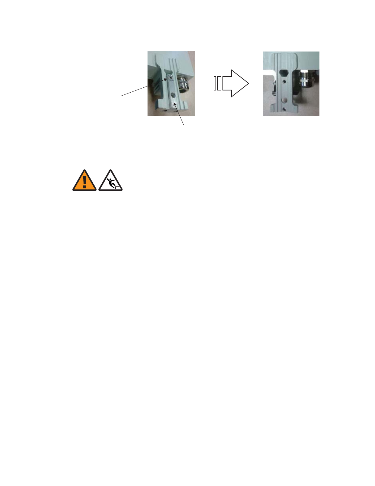
Installation of the 9764 Metro Dock
9764 Metro Dock installation
....................................................................................................................................................................................................................................
Procedure 3-1: Pole mount the 9764 Metro Dock
RAFT
D
M5x12
countersunk screw
Metro Dock pole mount using bolts
WARNING
Fall hazard
Falls can occur when working at heights resulting in serious personal injury or death.
To prevent a fall when working at heights (ladder, scaffold, manlift, roof etc.) follow safe
work practices and wear appropriate fall protection equipment.
Perform the following procedure to mount the 9764 Metro Dock onto a wooden pole
using bolts.
...................................................................................................................................................................................................
Measure the height at which the 9764 Metro Dock is to be positioned on the pole. Mark
1
this point.
...................................................................................................................................................................................................
Metro Dock
spacer
Metro Dock
spacer removed
Using a digital compass determine the planned horizontal (left/right) orientation of the
2
9764 Metro Dock around the pole. Mark this position.
...................................................................................................................................................................................................
At the identified 9764 Metro Dock position on the pole, mark the upper and lower bolt
3
anchor holes. The distance between the upper and lower bolt anchor holes should be 270
mm (10.63 inches).
Tip: The 9764 Metro Dock can be placed against the pole and used as a template to
mark the position of the upper and lower bolt anchor holes.
...................................................................................................................................................................................................
Place the 9764 Metro Dock against the pole aligning the upper and lower anchor holes on
4
the 9764 Metro Dock with the marked anchor hole positions on the pole.
....................................................................................................................................................................................................................................
3-20
RAFT
D
Proprietary – Use pursuant to Company instruction
Alcatel-Lucent – Internal
Alcatel-Lucent 9764 MCO
3MN-01707-0002-RJZZA
Issue 3.05 October 2014

Installation of the 9764 Metro Dock
9764 Metro Dock installation
....................................................................................................................................................................................................................................
Procedure 3-1: Pole mount the 9764 Metro Dock
Tip: Use an adjustable strap, cable ties or heavy duty duct tape to temporarily hold the
9764 Metro Dock against the pole while the bolts are applied.
...................................................................................................................................................................................................
Place a washer on each of the anchor bolts. Using socket wrench (M8) screw the 9764
5
Metro Dock onto the pole.
Recommended screw torque; 7.0 N.m (62.0 lb.in).
D
RAFT
Upper and lower
Metro Dock anchor holes
(9 mm diameter)
...................................................................................................................................................................................................
Finally, check the 9764 Metro Dock is secure and there is no movement of the equipment
6
on the pole.
E ND OF STEPS
...................................................................................................................................................................................................
Metro Dock pole mount using bands
WARNING
M8x50 stainless steel
hex head screw and
M8x16x1.6 plain washer
Fall hazard
Falls can occur when working at heights resulting in serious personal injury or death.
To prevent a fall when working at heights (ladder, scaffold, manlift, roof etc.) follow safe
work practices and wear appropriate fall protection equipment.
....................................................................................................................................................................................................................................
Alcatel-Lucent 9764 MCO
3MN-01707-0002-RJZZA
Issue 3.05 October 2014
Proprietary – Use pursuant to Company instruction
Alcatel-Lucent – Internal
3-21
D
RAFT

Installation of the 9764 Metro Dock
9764 Metro Dock installation
....................................................................................................................................................................................................................................
RAFT
D
Perform the following procedure to mount the 9764 Metro Dock onto a pole (wooden or
metal) using standard pole bands.
...................................................................................................................................................................................................
Measure the height at which the 9764 Metro Dock is to be positioned on the pole. Mark
1
Procedure 3-1: Pole mount the 9764 Metro Dock
this point.
...................................................................................................................................................................................................
Using a digital compass determine the planned horizontal (left/right) orientation of the
2
9764 Metro Dock around the pole. Mark this position.
...................................................................................................................................................................................................
From the banding installation kit, take a steel pole band and thread the open end into the
3
upper two slots on the 9764 Metro Dock.
Upper band
...................................................................................................................................................................................................
At the marked installation point on the pole place the upper pole band around the pole at
4
Upper Metro Dock
band slots
Metro Dock
the determined height. Carry out any required adjustment of the 9764 Metro Dock around
the pole so that it is pointing in the desired direction.
Tip: Use an adjustable strap, cable ties or heavy duty duct tape to temporarily hold the
9764 Metro Dock against the pole while the lower band is applied.
...................................................................................................................................................................................................
Taking the other steel band, place the band around the lower lug on the 9764 Metro Dock
5
and the pole.
....................................................................................................................................................................................................................................
3-22
RAFT
D
Proprietary – Use pursuant to Company instruction
Alcatel-Lucent – Internal
Alcatel-Lucent 9764 MCO
3MN-01707-0002-RJZZA
Issue 3.05 October 2014
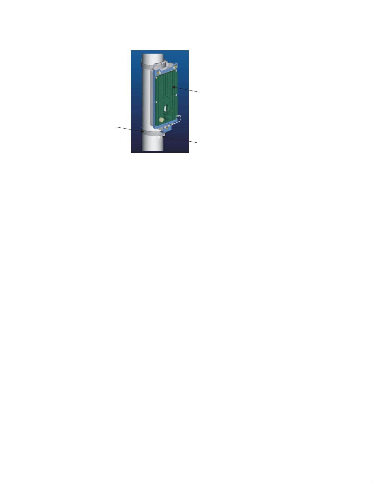
Installation of the 9764 Metro Dock
9764 Metro Dock installation
....................................................................................................................................................................................................................................
Metro Dock
Lower band
Lower band lug
...................................................................................................................................................................................................
Once the 9764 Metro Dock is in the correct position and orientation tighten and secure
6
the bands around the pole. Refer to BAND-IT
Procedure 3-1: Pole mount the 9764 Metro Dock
®
C00169 Hand Tool Operation
Instructions, PO5886.
D
RAFT
...................................................................................................................................................................................................
Finally, check the banding is secure, there is no movement of the 9764 Metro Dock
7
around the pole and that the banding stubs (cut ends) are flattened down with a hammer.
E ND OF STEPS
...................................................................................................................................................................................................
Standard pole mount example
The following figure shows the 9764 Metro Dock mounted onto a wooden pole using
bolts and a metal pole using bands.
....................................................................................................................................................................................................................................
Alcatel-Lucent 9764 MCO
3MN-01707-0002-RJZZA
Issue 3.05 October 2014
Proprietary – Use pursuant to Company instruction
Alcatel-Lucent – Internal
3-23
D
RAFT

Installation of the 9764 Metro Dock
9764 Metro Dock installation
....................................................................................................................................................................................................................................
Procedure 3-1: Pole mount the 9764 Metro Dock
RAFT
D
Metro Dock screwed
How to continue
After mounting the 9764 Metro Dock onto a pole the cables need to be connected.
Continue with the,
onto wooden pole
Metro Dock banded
onto metal pole
“9764 Metro Dock cabling” (p. 3-89) section.
....................................................................................................................................................................................................................................
3-24
RAFT
D
Proprietary – Use pursuant to Company instruction
Alcatel-Lucent – Internal
Alcatel-Lucent 9764 MCO
3MN-01707-0002-RJZZA
Issue 3.05 October 2014

Installation of the 9764 Metro Dock
9764 Metro Dock installation
....................................................................................................................................................................................................................................
Procedure 3-2: Pole mount the 9764 Metro Dock using
optional tilt brackets
Procedure 3-2: Pole mount the 9764 Metro Dock using optional tilt brackets
Purpose
This topic describes the procedures to be followed when installing the Alcatel-Lucent
9764 Metro Dock onto a pole (wooden or metal) using optional vertical tilt brackets.
Prerequisites
A site survey has been conducted and a location for the device has been selected that is
both central to the public space and elevated in order to maximize coverage. Before
installation begins you should ensure the following are in place:
• Ensure adequate clearance is provided for service access
• Ground cable has been routed and the site grounding system is in place
• Backhaul cable has been routed and is in place
• Any site specific mounting and anchor materials are available.
D
RAFT
Attention: The 9764 Metro Dock must be mounted with the appropriate mounting
hardware suitable for the various supporting structures, building materials and
construction methods. Following a site survey, it is the responsibility of the customer
to ensure that:
• the installation support structure is adequate and compliant with ICC IBC (2012):
International Building Code, and all other national and local codes
• the appropriate mounting hardware and any necessary supporting material is used.
Mounting requirements and materials
The 9764 Metro Dock can be mounted onto a wooden or metal pole. Refer to the
following for the installation kits, anchor materials and tools for the installation type:
• For pole mount refer to,
• For a list of standard tools that may be required to support the installation, refer to
“Tools required for installation” (p. 3-4)
Before you begin
Record the 9764 Metro Dock 18 digit serial number before mounting onto a pole.
“Pole mount installation requirements” (p. 3-5).
....................................................................................................................................................................................................................................
Alcatel-Lucent 9764 MCO
3MN-01707-0002-RJZZA
Issue 3.05 October 2014
Proprietary – Use pursuant to Company instruction
Alcatel-Lucent – Internal
3-25
D
RAFT

Installation of the 9764 Metro Dock
9764 Metro Dock installation
....................................................................................................................................................................................................................................
Bracket pole mount using bolts
RAFT
Procedure 3-2: Pole mount the 9764 Metro Dock using
optional tilt brackets
D
WARNING
Fall hazard
Falls can occur when working at heights resulting in serious personal injury or death.
To prevent a fall when working at heights (ladder, scaffold, manlift, roof etc.) follow safe
work practices and wear appropriate fall protection equipment.
Perform the following procedure attach the vertical tilt bracket a wooden pole using bolts.
...................................................................................................................................................................................................
Measure the height at which the 9764 Metro Dock is to be positioned on the pole. Mark
1
this point.
...................................................................................................................................................................................................
Using a digital compass determine the planned horizontal (left/right) orientation of the
2
9764 Metro Dock around the pole. Mark this position.
...................................................................................................................................................................................................
At the identified 9764 Metro Dock position on the pole, mark the upper and lower bolt
3
anchor holes for the tilt bracket. The distance between the upper and lower bolt anchor
holes should be 200 mm (7.87 inches).
Tip: The vertical tilt bracket can be placed against the pole and used as a template to
mark the position of the upper and lower bolt holes.
...................................................................................................................................................................................................
Depending on the required vertical tilt orientation ensure the bracket is positioned the
4
correct way up before placing on the pole:
If... Then... View...
upward vertical tilt is
required
the tilt bracket must be
positioned with the pivot point
at the top
....................................................................................................................................................................................................................................
3-26
RAFT
D
Proprietary – Use pursuant to Company instruction
Alcatel-Lucent – Internal
Alcatel-Lucent 9764 MCO
3MN-01707-0002-RJZZA
Issue 3.05 October 2014
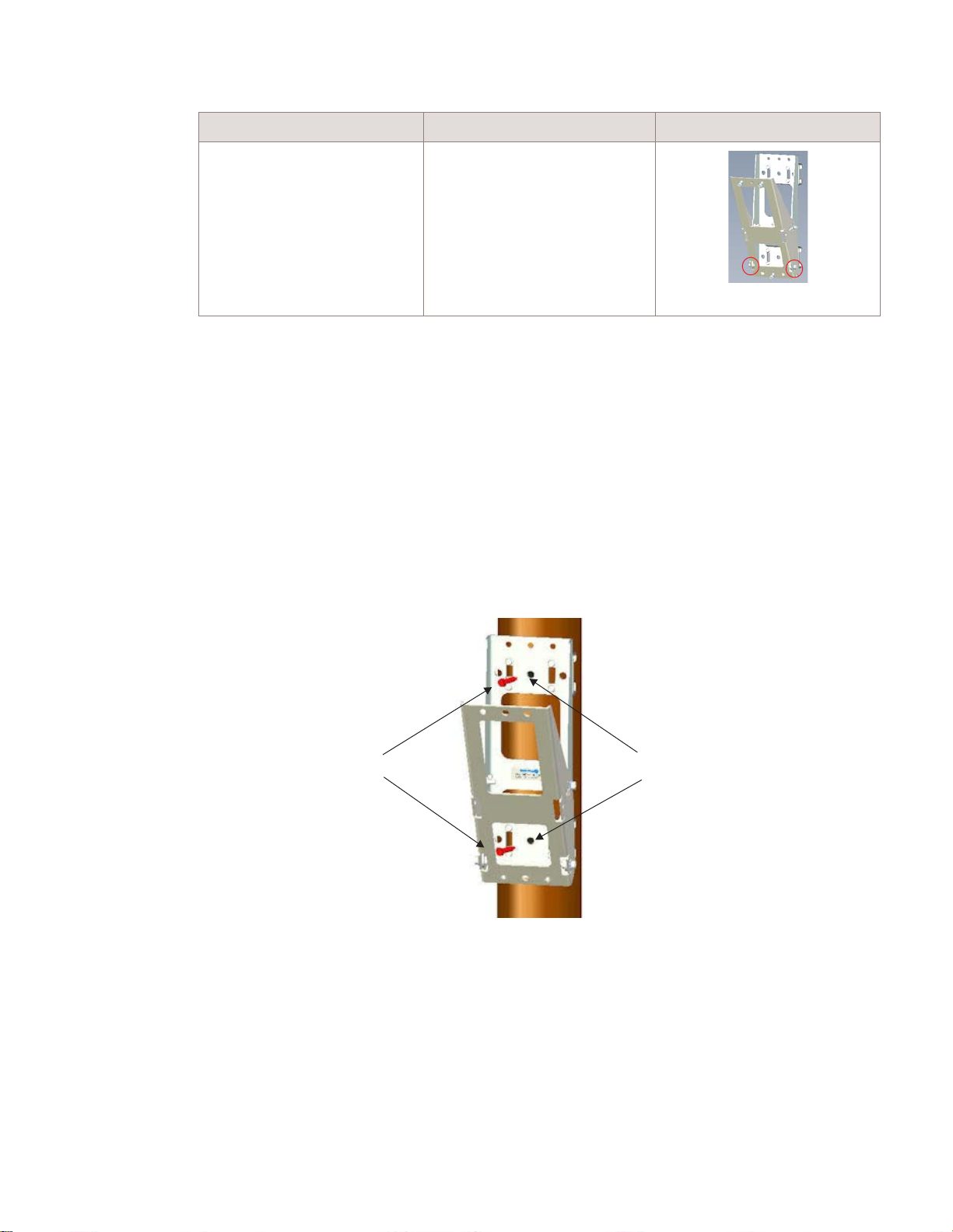
Installation of the 9764 Metro Dock
9764 Metro Dock installation
....................................................................................................................................................................................................................................
Procedure 3-2: Pole mount the 9764 Metro Dock using
optional tilt brackets
If... Then... View...
D
RAFT
downward vertical tilt is
required
the tilt bracket must be
positioned with the pivot point
at the bottom
...................................................................................................................................................................................................
Place the vertical tilt bracket against the pole aligning the upper and lower anchor holes
5
on the bracket with the marked bolt hole positions on the pole.
Tip: Use an adjustable strap, cable ties or heavy duty duct tape to temporarily hold the
9764 Metro Dock against the pole while the bolts are applied.
...................................................................................................................................................................................................
Place a washer on each of the anchor bolts. Using a socket wrench (M8) screw the
6
vertical tilt bracket onto the pole.
Recommended screw torque; 7.0 N.m (62.0 lb.in).
M8x50 stainless steel
hex head screw and
M8x16x1.6 plain washer
...................................................................................................................................................................................................
Finally, check the bolts are secure and there is no movement of the bracket on the pole.
7
....................................................................................................................................................................................................................................
Alcatel-Lucent 9764 MCO
3MN-01707-0002-RJZZA
Issue 3.05 October 2014
Proprietary – Use pursuant to Company instruction
Alcatel-Lucent – Internal
Upper and lower
Metro Dock anchor holes
(9 mm diameter)
3-27
D
RAFT

Installation of the 9764 Metro Dock
9764 Metro Dock installation
....................................................................................................................................................................................................................................
RAFT
D
...................................................................................................................................................................................................
Continue onto “Attach 9764 Metro Dock to the tilt bracket” (p. 3-30)
8
E ND OF STEPS
...................................................................................................................................................................................................
Procedure 3-2: Pole mount the 9764 Metro Dock using
optional tilt brackets
Bracket pole mount using bands
WARNING
Fall hazard
Falls can occur when working at heights resulting in serious personal injury or death.
To prevent a fall when working at heights (ladder, scaffold, manlift, roof etc.) follow safe
work practices and wear appropriate fall protection equipment.
Perform the following procedure to mount the vertical tilt bracket onto a pole (wooden or
metal) using standard pole bands.
...................................................................................................................................................................................................
Measure the height at which the 9764 Metro Dock is to be positioned on the pole. Mark
1
this point.
...................................................................................................................................................................................................
Using a digital compass determine the planned horizontal (left/right) orientation of the
2
9764 Metro Dock around the pole. Mark this position.
...................................................................................................................................................................................................
From the banding installation kit, take a steel pole band and thread the open end into the
3
upper two slots on the tilt bracket.
Taking the other steel band insert and thread the open end into the lower two slots on the
tilt bracket.
....................................................................................................................................................................................................................................
3-28
RAFT
D
Proprietary – Use pursuant to Company instruction
Alcatel-Lucent – Internal
Alcatel-Lucent 9764 MCO
3MN-01707-0002-RJZZA
Issue 3.05 October 2014

Installation of the 9764 Metro Dock
9764 Metro Dock installation
....................................................................................................................................................................................................................................
...................................................................................................................................................................................................
Depending on the required vertical tilt orientation ensure the bracket is positioned the
4
Procedure 3-2: Pole mount the 9764 Metro Dock using
optional tilt brackets
correct way up before placing on the pole:
D
RAFT
If... Then... View...
upward vertical tilt is
required
the tilt bracket must be
positioned with the pivot point
at the top
downward vertical tilt is
required
the tilt bracket must be
positioned with the pivot point
at the bottom
...................................................................................................................................................................................................
At the marked installation position on the pole wrap the upper and lower pole bands
5
around the pole at the determined height. Carry out any required adjustment of the 9764
Metro Dock around the pole so that it is pointing in the planned direction.
Tip: Use an adjustable strap, cable ties or heavy duty duct tape to temporarily hold the
9764 Metro Dock against the pole while the bands are applied.
....................................................................................................................................................................................................................................
Alcatel-Lucent 9764 MCO
3MN-01707-0002-RJZZA
Issue 3.05 October 2014
Proprietary – Use pursuant to Company instruction
Alcatel-Lucent – Internal
3-29
D
RAFT

Installation of the 9764 Metro Dock
9764 Metro Dock installation
....................................................................................................................................................................................................................................
RAFT
D
...................................................................................................................................................................................................
Once the 9764 Metro Dock is in the correct position and orientation tighten and secure
6
the bands around the pole. Refer to BAND-IT
Procedure 3-2: Pole mount the 9764 Metro Dock using
®
C00169 Hand Tool Operation
optional tilt brackets
Instructions, PO5886.
...................................................................................................................................................................................................
Finally, check the banding is secure, there is no movement of the bracket around the pole
7
and that the banding stubs (cut ends) are flattened down with a hammer.
Banding stubs
(cut ends)
Rear view
...................................................................................................................................................................................................
Continue onto “Attach 9764 Metro Dock to the tilt bracket” (p. 3-30)
8
E ND OF STEPS
...................................................................................................................................................................................................
Attach 9764 Metro Dock to the tilt bracket
WARNING
Fall hazard
Falls can occur when working at heights resulting in serious personal injury or death.
To prevent a fall when working at heights (ladder, scaffold, manlift, roof etc.) follow safe
work practices and wear appropriate fall protection equipment.
Perform the following procedure to attach the 9764 Metro Dock to the tilt bracket.
...................................................................................................................................................................................................
Before attaching the 9764 Metro Dock to the tilt bracket ensure that the Metro Dock
1
spacer is fitted and in place.
....................................................................................................................................................................................................................................
3-30
RAFT
D
Proprietary – Use pursuant to Company instruction
Alcatel-Lucent – Internal
Alcatel-Lucent 9764 MCO
3MN-01707-0002-RJZZA
Issue 3.05 October 2014
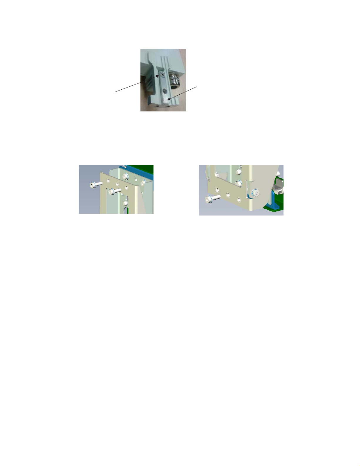
Installation of the 9764 Metro Dock
9764 Metro Dock installation
....................................................................................................................................................................................................................................
Procedure 3-2: Pole mount the 9764 Metro Dock using
optional tilt brackets
D
RAFT
M5x12
countersunk screw
...................................................................................................................................................................................................
Unscrew and remove the two upper M6 bolts and the one lower M6 bolt from the tilt
2
Metro Dock
spacer
bracket.
Upper M6 bolts x 2
...................................................................................................................................................................................................
Lower M6 bolt x 1
Position the 9764 Metro Dock against the front of the tilt bracket so that the two upper
3
bolt holes and the single lower bolt hole on the 9764 Metro Dock are aligned with the
bolts holes on the tilt bracket.
...................................................................................................................................................................................................
From the 9764 Metro Dock side, screw in the two M6 bolts through the upper bolt holes
4
on the 9764 Metro Dock and into the upper tilt bracket bolt holes.
....................................................................................................................................................................................................................................
Alcatel-Lucent 9764 MCO
3MN-01707-0002-RJZZA
Issue 3.05 October 2014
Proprietary – Use pursuant to Company instruction
Alcatel-Lucent – Internal
3-31
D
RAFT
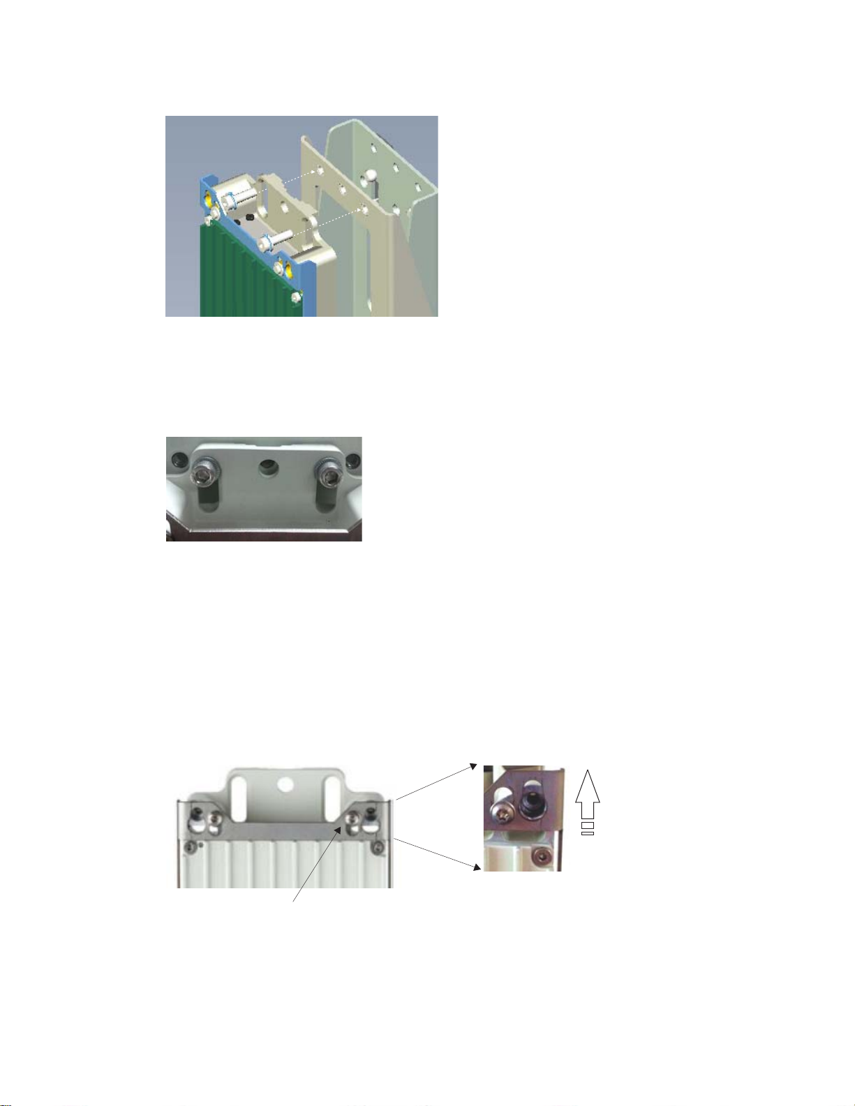
Installation of the 9764 Metro Dock
9764 Metro Dock installation
....................................................................................................................................................................................................................................
Procedure 3-2: Pole mount the 9764 Metro Dock using
optional tilt brackets
RAFT
D
Note: Ensure the bolts are positioned at the upper (or lower) part of the elongated hole
for better contact area with the Metro Dock (the chamfered midsection of the
elongated hole is used for banding installation).
...................................................................................................................................................................................................
Move the 9764 Metro Dock metal slider to the “up” position as this allows easier access
5
to the lower attachment bolt hole:
1. insert supplied key into lock
2. turn the key to its hard stop position to unlock the slider
3. push the slider upwards and turn the key to its hard stop position. The slider is now
locked in the “up” position.
Slider moves upwards
Metro Dock Slider
(in down position)
....................................................................................................................................................................................................................................
3-32
RAFT
D
Proprietary – Use pursuant to Company instruction
Alcatel-Lucent – Internal
Alcatel-Lucent 9764 MCO
3MN-01707-0002-RJZZA
Issue 3.05 October 2014
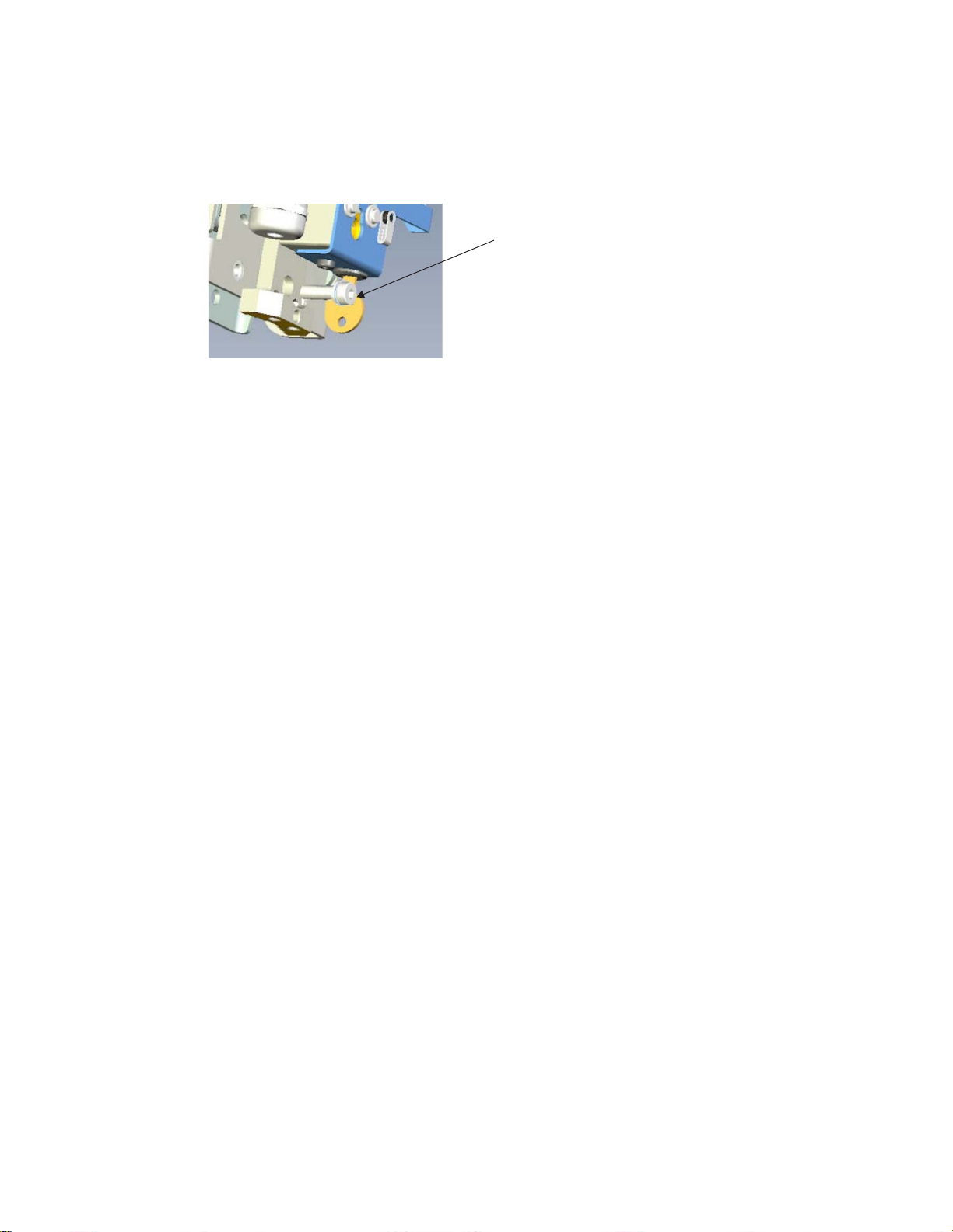
Installation of the 9764 Metro Dock
9764 Metro Dock installation
....................................................................................................................................................................................................................................
...................................................................................................................................................................................................
From the 9764 Metro Dock side, screw in t the single M6 bolts through the lower bolt
6
Procedure 3-2: Pole mount the 9764 Metro Dock using
optional tilt brackets
hole on the 9764 Metro Dock and into the lower tilt bracket bolt hole.
Lower Metro Dock
attachment bolt
...................................................................................................................................................................................................
Using a 10 mm ratchet wrench, tighten the two upper and one lower M6 retaining bolts.
7
Recommended screw torque; 7.0 N.m (62.0 lb.in).
...................................................................................................................................................................................................
D
RAFT
Finally move the 9764 Metro Dock metal slider to the “down” position:
8
1. turn the key to its hard stop position to unlock the slider. The slider will automatically
spring into the “down” position.
2. turn the key to its hard stop position. The slider is now locked in the “down” position
and the key can be removed from the lock.
E ND OF STEPS
...................................................................................................................................................................................................
Pole mount example (with vertical tilt)
The following figure shows the 9764 Metro Dock, with vertical tilt, mounted onto a
wooden pole using bolts and a metal pole using bands.
....................................................................................................................................................................................................................................
Alcatel-Lucent 9764 MCO
3MN-01707-0002-RJZZA
Issue 3.05 October 2014
Proprietary – Use pursuant to Company instruction
Alcatel-Lucent – Internal
3-33
D
RAFT
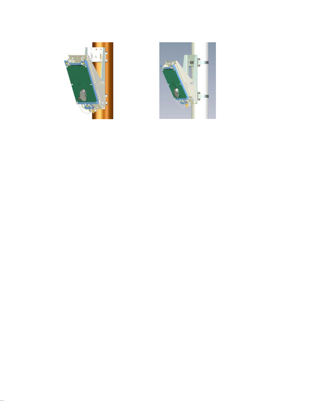
Installation of the 9764 Metro Dock
9764 Metro Dock installation
....................................................................................................................................................................................................................................
Procedure 3-2: Pole mount the 9764 Metro Dock using
optional tilt brackets
RAFT
D
How to continue
After mounting the 9764 Metro Dock onto a pole the cables need to be connected.
Continue with the,
Metro Dock mounted on
wooden pole with vertical tilt
“9764 Metro Dock cabling” (p. 3-89) section.
Metro Dock mounted on
metal pole with vertical tilt
....................................................................................................................................................................................................................................
3-34
RAFT
D
Proprietary – Use pursuant to Company instruction
Alcatel-Lucent – Internal
Alcatel-Lucent 9764 MCO
3MN-01707-0002-RJZZA
Issue 3.05 October 2014

Installation of the 9764 Metro Dock
9764 Metro Dock installation
....................................................................................................................................................................................................................................
Procedure 3-3: Wall mount the 9764 Metro Dock
Procedure 3-3: Wall mount the 9764 Metro Dock
Purpose
This topic describes the procedures to be followed when installing the Alcatel-Lucent
9764 Metro Dock directly onto a wall or solid flat surface.
Prerequisites
A site survey has been conducted and a location for the device has been selected that is
both central to the public space and elevated in order to maximize coverage. Before
installation begins you should ensure the following are in place:
• Ensure adequate clearance is provided for service access
• Ground cable has been routed and the site grounding system is in place
• Backhaul cable has been routed and is in place
• Any site specific fixing materials are available (for example, bolts, washers and wall
plug materials).
D
RAFT
Attention: The 9764 Metro Dock must be mounted with the appropriate mounting
hardware suitable for the various supporting structures, building materials and
construction methods. Following a site survey, it is the responsibility of the customer
to ensure that:
• the installation support structure is adequate and compliant with ICC IBC (2012):
International Building Code, and all other national and local codes
• the appropriate mounting hardware and any necessary recommended supporting
anchor fixings are used.
Mounting requirements and materials
The 9764 Metro Dock is less than 1 kg (2.2 lbs) and can be easily mounted onto solid
concrete or wooden flat surface. Refer to the following for the installation kits, anchor
materials and tools for the installation type:
• For wall mount refer to,
• For a list of standard tools that may be required to support the installation, see
required for installation” (p. 3-4)
Before you begin
“Wall mount installation requirements” (p. 3-9).
“Tools
Before mounting the 9764 Metro Dock:
• Record the 9764 Metro Dock 18 digit serial number
• On the 9764 Metro Dock ensure that the Metro Dock spacer is not attached. If the
spacer is present remove it by unscrewing the M5 screw:
....................................................................................................................................................................................................................................
Alcatel-Lucent 9764 MCO
3MN-01707-0002-RJZZA
Issue 3.05 October 2014
Proprietary – Use pursuant to Company instruction
Alcatel-Lucent – Internal
3-35
D
RAFT

Installation of the 9764 Metro Dock
9764 Metro Dock installation
....................................................................................................................................................................................................................................
Procedure 3-3: Wall mount the 9764 Metro Dock
RAFT
D
M5x12
countersunk screw
Perform standard wall mount installation
WARNING
Fall hazard
Falls can occur when working at heights resulting in serious personal injury or death.
To prevent a fall when working at heights (ladder, scaffold, manlift, roof etc.) follow safe
work practices and wear appropriate fall protection equipment.
Perform the following procedure to mount the 9764 Metro Dock directly onto a wall.
...................................................................................................................................................................................................
Measure the height at which the 9764 Metro Dock is to be positioned on the wall. Mark
1
this point.
...................................................................................................................................................................................................
At the selected installation location, mark the points on the wall for the anchor holes. See
2
hole spacing pattern below to use as a guide:
Metro Dock
spacer
Metro Dock
spacer removed
....................................................................................................................................................................................................................................
3-36
RAFT
D
Proprietary – Use pursuant to Company instruction
Alcatel-Lucent – Internal
Alcatel-Lucent 9764 MCO
3MN-01707-0002-RJZZA
Issue 3.05 October 2014

Installation of the 9764 Metro Dock
9764 Metro Dock installation
....................................................................................................................................................................................................................................
52mm
(2.05 inches)
267mm
(10.51 inches)
Procedure 3-3: Wall mount the 9764 Metro Dock
D
RAFT
Tip: The wall spacer bracket can placed against the wall and used as a template to
mark the position of the upper and lower anchor holes.
Check the horizontal position of the planned holes with a level.
...................................................................................................................................................................................................
3
If.. Then..
Surface structure is concrete
1. Drill two upper holes and one lower hole at the
marked points to the appropriate depth.
2. Insert screw anchor plugs (Rawlnut M6x50) into the
drilled holes and, using a hammer, tap home until
the plugs are flush with the wall.
Surface structure is wood Proceed with the next step.
...................................................................................................................................................................................................
Move the 9764 Metro Dock metal slider to the “up” position as this allows easier access
4
to the lower attachment bolt hole:
1. insert supplied key into lock
2. turn the key to its hard stop position to unlock the slider
3. Push the slider upwards and turn the key to its hard stop position. The slider is now
locked in the “up” position.
....................................................................................................................................................................................................................................
Alcatel-Lucent 9764 MCO
3MN-01707-0002-RJZZA
Issue 3.05 October 2014
Proprietary – Use pursuant to Company instruction
Alcatel-Lucent – Internal
3-37
D
RAFT

Installation of the 9764 Metro Dock
9764 Metro Dock installation
....................................................................................................................................................................................................................................
Procedure 3-3: Wall mount the 9764 Metro Dock
RAFT
D
Slider moves upwards
Metro Dock Slider
(in down position)
...................................................................................................................................................................................................
Place washers onto the anchor bolts.
5
Note: The type of anchor bolt used depends on the surface structure:
• Wooden surface: use Screw Hex T M8x70 stainless steel
• Concrete surface: use Screw CHC M6x80 stainless steel
...................................................................................................................................................................................................
Align the 9764 Metro Dock bolt holes with the wall spacer bolt holes and thread bolts
6
through the corresponding set of holes.
...................................................................................................................................................................................................
Screw in the upper and lower bolts into the drilled anchor holes for a concrete surface, or
7
directly into the wooden surface, to the appropriate depth so that the wall spacer and 9764
Metro Dock are securely attached to the wall.
Recommended screw torque; 7.0 N.m (62.0 lb.in).
....................................................................................................................................................................................................................................
3-38
RAFT
D
Proprietary – Use pursuant to Company instruction
Alcatel-Lucent – Internal
Alcatel-Lucent 9764 MCO
3MN-01707-0002-RJZZA
Issue 3.05 October 2014

Installation of the 9764 Metro Dock
9764 Metro Dock installation
....................................................................................................................................................................................................................................
...................................................................................................................................................................................................
Finally move the 9764 Metro Dock metal slider to the “down” position:
8
Procedure 3-3: Wall mount the 9764 Metro Dock
1. turn the key to its hard stop position to unlock the slider. The slider will automatically
spring into the “down” position
2. turn the key to its hard stop position. The slider is now locked in the “down” position
and the key can be removed from the lock.
E ND OF STEPS
...................................................................................................................................................................................................
Standard wall mount example
The following figure depicts a standard wall mount.
D
RAFT
How to continue
After mounting the 9764 Metro Dock onto a wall the cables need to be connected.
Continue with the,
....................................................................................................................................................................................................................................
Alcatel-Lucent 9764 MCO
3MN-01707-0002-RJZZA
Issue 3.05 October 2014
“9764 Metro Dock cabling” (p. 3-89) section.
Alcatel-Lucent – Internal
Proprietary – Use pursuant to Company instruction
3-39
D
RAFT

Installation of the 9764 Metro Dock
9764 Metro Dock installation
....................................................................................................................................................................................................................................
RAFT
Procedure 3-4: Wall mount the 9764 Metro Dock using optional
D
tilt brackets
Purpose
Procedure 3-4: Wall mount the 9764 Metro Dock using
optional tilt brackets
This topic describes the procedures to be followed when the Alcatel-Lucent 9764 Metro
Dock is required to be mounted onto a wall or solid flat surface using tilt brackets
(vertical, horizontal or combined horizontal/vertical).
Prerequisites
A site survey has been conducted and a location for the device has been selected that is
both central to the public space and elevated in order to maximize coverage. Before
installation begins you should ensure the following are in place:
• Ensure adequate clearance is provided for service access
• Ground cable has been routed and the site grounding system is in place
• Backhaul cable has been routed and is in place
• Any site specific fixing materials are available (for example, bolts, washers and wall
plug materials).
Attention: The 9764 Metro Dock must be mounted with the appropriate mounting
hardware suitable for the various supporting structures, building materials and
construction methods. Following a site survey, it is the responsibility of the customer
to ensure that:
• the installation support structure is adequate and compliant with ICC IBC (2012):
International Building Code, and all other national and local codes
• the appropriate mounting hardware and any necessary supporting anchor fixings
are used.
Mounting requirements and materials
The 9764 Metro Dock is less than 1 kg (2.2 lbs) and can be easily mounted onto solid
concrete or wooden flat surface. Refer to the following for the installation kits, anchor
materials and tools for the installation type:
• For wall mount refer to,
• For a list of standard tools that may be required to support the installation, see
required for installation” (p. 3-4)
“Wall mount installation requirements” (p. 3-9).
“Tools
Before you begin
Record the 9764 Metro Dock 18 digit serial number before mounting onto a wall.
....................................................................................................................................................................................................................................
3-40
RAFT
D
Proprietary – Use pursuant to Company instruction
Alcatel-Lucent – Internal
Alcatel-Lucent 9764 MCO
3MN-01707-0002-RJZZA
Issue 3.05 October 2014

Installation of the 9764 Metro Dock
9764 Metro Dock installation
....................................................................................................................................................................................................................................
Procedure 3-4: Wall mount the 9764 Metro Dock using
optional tilt brackets
Prepare surface for bracket mounting
WARNING
Fall hazard
Falls can occur when working at heights resulting in serious personal injury or death.
To prevent a fall when working at heights (ladder, scaffold, manlift, roof etc.) follow safe
work practices and wear appropriate fall protection equipment.
Perform the following procedure to prepare a wall or solid flat surface for mounting tilt
brackets.
...................................................................................................................................................................................................
At the selected installation location, mark the points on the wall for the bracket anchor
1
holes. See drill hole pattern below to use as a guide:
52 mm
(2.05 inches)
D
RAFT
(10.63 inches)
270 mm
Tip: If the tilt bracket is available it can be placed against the wall and be used as a
template to mark the points on the wall for the bracket anchor holes.
Check the horizontal marked position of the holes with a level.
D
....................................................................................................................................................................................................................................
Alcatel-Lucent 9764 MCO
3MN-01707-0002-RJZZA
Issue 3.05 October 2014
Proprietary – Use pursuant to Company instruction
Alcatel-Lucent – Internal
3-41
RAFT

Installation of the 9764 Metro Dock
9764 Metro Dock installation
....................................................................................................................................................................................................................................
RAFT
D
...................................................................................................................................................................................................
2
Procedure 3-4: Wall mount the 9764 Metro Dock using
optional tilt brackets
If.. Then..
Surface structure is concrete
1. Drill two upper holes and one lower hole at the
marked points to the appropriate depth.
2. Insert screw anchor plugs (Rawlnut M6x50) into the
drilled holes and, using a hammer, tap home until
the plugs are flush with the wall.
Surface structure is wood Mount combined horizontal/vertical tilt brackets
...................................................................................................................................................................................................
Once the mounting surface has been prepared the tilt brackets can be attached. Continue
3
with one of the following procedures depending on the tilt configuration:
If.. Then..
Attaching vertical tilt
brackets
Attaching horizontal tilt
brackets
Attaching combined
horizontal and vertical tilt
brackets
Carry out the procedure,
“Mount the vertical tilt bracket”
(p. 3-42)
Carry out the procedure, “Mount the horizontal tilt bracket”
(p. 3-44)
Carry out the procedure,
“Mount combined horizontal/vertical
tilt brackets” (p. 3-46)
E ND OF STEPS
...................................................................................................................................................................................................
Mount the vertical tilt bracket
WARNING
Fall hazard
Falls can occur when working at heights resulting in serious personal injury or death.
To prevent a fall when working at heights (ladder, scaffold, manlift, roof etc.) follow safe
work practices and wear appropriate fall protection equipment.
....................................................................................................................................................................................................................................
3-42
RAFT
D
Proprietary – Use pursuant to Company instruction
Alcatel-Lucent – Internal
Alcatel-Lucent 9764 MCO
3MN-01707-0002-RJZZA
Issue 3.05 October 2014
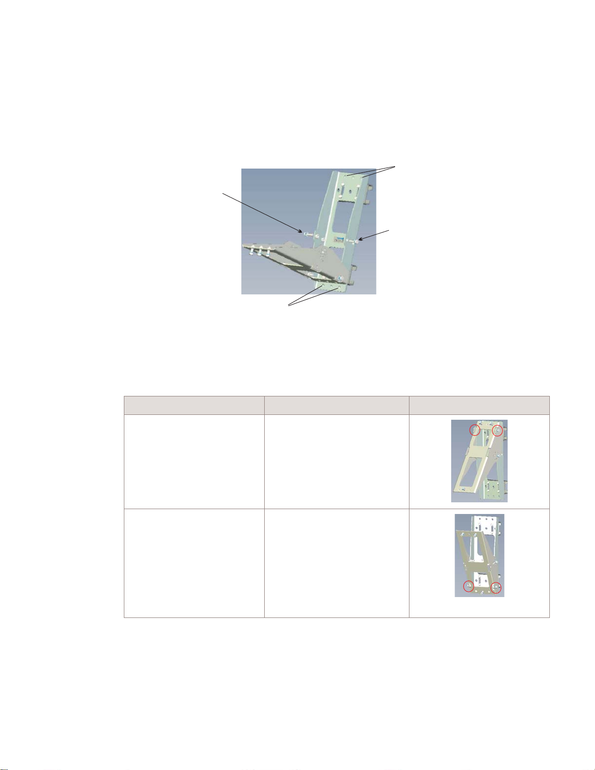
Installation of the 9764 Metro Dock
9764 Metro Dock installation
....................................................................................................................................................................................................................................
Procedure 3-4: Wall mount the 9764 Metro Dock using
optional tilt brackets
Perform the following procedure to attach a vertical tilt bracket onto a flat surface or wall.
...................................................................................................................................................................................................
Remove the two tilt angle positioning gauge bolts on either side of the vertical tilt bracket
1
and allow the front part of the bracket to pivot away allowing easier access to the bracket
anchor holes.
Bracket anchor holes
Tilt angle positioning
gauge bolt
Tilt angle positioning
gauge bolt
Bracket anchor holes
D
RAFT
...................................................................................................................................................................................................
Depending on the required vertical tilt orientation ensure the bracket is positioned the
2
correct way up before placing on the wall:
If... Then... View...
upward vertical tilt is
required
downward vertical tilt is
required
the tilt bracket must be
positioned with the pivot point
at the top
the tilt bracket must be
positioned with the pivot point
at the bottom
...................................................................................................................................................................................................
Place washers onto the anchor bolts.
3
....................................................................................................................................................................................................................................
Alcatel-Lucent 9764 MCO
3MN-01707-0002-RJZZA
Issue 3.05 October 2014
Proprietary – Use pursuant to Company instruction
Alcatel-Lucent – Internal
3-43
D
RAFT

Installation of the 9764 Metro Dock
9764 Metro Dock installation
....................................................................................................................................................................................................................................
RAFT
D
Note: The type of anchor bolt used depends on the surface structure:
• Wooden surface: use Screw Hex T M8x70 stainless steel
Procedure 3-4: Wall mount the 9764 Metro Dock using
optional tilt brackets
• Concrete surface: use Screw CHC M6x80 stainless steel
...................................................................................................................................................................................................
At the selected installation location, position the tilt bracket so the anchor holes on the
4
bracket align with the anchor holes either drilled or marked on the wall.
...................................................................................................................................................................................................
For each anchor hole (upper and lower) insert bolts through the tilt bracket anchor holes.
5
...................................................................................................................................................................................................
Screw the upper and lower bolts into the drilled anchor holes for a concrete surface, or
6
directly into the wooden surface, to the appropriate depth so that the bracket is firmly
secured to the wall or flat surface.
Recommended screw torque; 7.0 N.m (62.0 lb.in).
...................................................................................................................................................................................................
Once the tilt bracket is mounted the 9764 Metro Dock can be attached. Continue with
7
“Attach 9764 Metro Dock to the tilt bracket” (p. 3-30).
E ND OF STEPS
...................................................................................................................................................................................................
Mount the horizontal tilt bracket
WARNING
Fall hazard
Falls can occur when working at heights resulting in serious personal injury or death.
To prevent a fall when working at heights (ladder, scaffold, manlift, roof etc.) follow safe
work practices and wear appropriate fall protection equipment.
Perform the following procedure to attach the horizontal tilt bracket onto a flat surface or
wall.
...................................................................................................................................................................................................
Remove the two tilt angle positioning gauge bolts from the top and bottom of the
1
horizontal tilt bracket and allow the front part of the bracket to pivot away allowing easier
access to the bracket anchor holes.
....................................................................................................................................................................................................................................
3-44
RAFT
D
Proprietary – Use pursuant to Company instruction
Alcatel-Lucent – Internal
Alcatel-Lucent 9764 MCO
3MN-01707-0002-RJZZA
Issue 3.05 October 2014

Installation of the 9764 Metro Dock
9764 Metro Dock installation
....................................................................................................................................................................................................................................
Tilt angle
positioning gauge bolt
Tilt angle
positioning gauge bolt
...................................................................................................................................................................................................
Depending on the required horizontal tilt orientation ensure the bracket is the correct way
2
Procedure 3-4: Wall mount the 9764 Metro Dock using
optional tilt brackets
Bracket anchor holes
Bracket anchor holes
up before securing the bracket onto the wall:
D
RAFT
If... Then... View...
left horizontal tilt is required the tilt bracket must be
positioned with the pivot point
on the left
right horizontal tilt is required the tilt bracket must be
positioned with the pivot point
on the right
...................................................................................................................................................................................................
Place washers onto the anchor bolts.
3
Note: The type of anchor bolt used depends on the surface structure:
• Wooden surface: use Screw Hex T M8x70 stainless steel
• Concrete surface: use Screw CHC M6x80 stainless steel
....................................................................................................................................................................................................................................
Alcatel-Lucent 9764 MCO
3MN-01707-0002-RJZZA
Issue 3.05 October 2014
Proprietary – Use pursuant to Company instruction
Alcatel-Lucent – Internal
3-45
D
RAFT
Installation of the 9764 Metro Dock
9764 Metro Dock installation
....................................................................................................................................................................................................................................
RAFT
D
...................................................................................................................................................................................................
At the selected installation location, position the tilt bracket so the anchor holes on the
4
Procedure 3-4: Wall mount the 9764 Metro Dock using
optional tilt brackets
bracket align with the anchor holes either drilled or marked on the wall.
...................................................................................................................................................................................................
For each anchor hole (upper and lower) insert bolts through the tilt bracket anchor holes.
5
...................................................................................................................................................................................................
Screw the upper and lower bolts into the drilled anchor holes for a concrete surface, or
6
directly into the wooden surface, to the appropriate depth so that the bracket is firmly
secured to the wall or flat surface.
Recommended screw torque; 7.0 N.m (62.0 lb.in).
...................................................................................................................................................................................................
Once the tilt bracket is mounted the 9764 Metro Dock can be attached. Continue with
7
“Attach 9764 Metro Dock to the tilt bracket” (p. 3-30).
E ND OF STEPS
...................................................................................................................................................................................................
Mount combined horizontal/vertical tilt brackets
WARNING
Fall hazard
Falls can occur when working at heights resulting in serious personal injury or death.
To prevent a fall when working at heights (ladder, scaffold, manlift, roof etc.) follow safe
work practices and wear appropriate fall protection equipment.
Perform the following procedure to attach the combined horizontal/vertical tilt bracket
onto a flat surface or wall.
...................................................................................................................................................................................................
Firstly combine the horizontal and vertical tilt brackets.
1
Unscrew and remove the two upper and two lower M6 bolts on the front of the horizontal
tilt bracket.
....................................................................................................................................................................................................................................
3-46
RAFT
D
Proprietary – Use pursuant to Company instruction
Alcatel-Lucent – Internal
Alcatel-Lucent 9764 MCO
3MN-01707-0002-RJZZA
Issue 3.05 October 2014

Installation of the 9764 Metro Dock
9764 Metro Dock installation
....................................................................................................................................................................................................................................
...................................................................................................................................................................................................
Align the attachment holes on the vertical tilt bracket with the attachments holes on the
2
Procedure 3-4: Wall mount the 9764 Metro Dock using
optional tilt brackets
horizontal tilt bracket.
D
RAFT
Important! Ensure the brackets are combined in the correct way based on the planned
horizontal and vertical tilt orientation of the equipment.
If... Then... View...
left horizontal tilt and
downward vertical tilt is
required
or
right horizontal tilt and
upward vertical tilt is required
right horizontal tilt and
downward vertical tilt is
required
or
left horizontal tilt and upward
vertical tilt is required
the brackets should be attached with
the horizontal bracket pivot point on
the left and the vertical bracket pivot
point at the bottom
Note: when positioning on a wall the
bracket assembly can be turned
through 180
0
for right horizontal tilt
and upward vertical tilt
the brackets should be attached with
the horizontal bracket pivot point on
the right and the vertical bracket pivot
point at the bottom
Note: when positioning on a wall the
bracket assembly can be turned
through 180
0
for left horizontal tilt and
upward vertical tilt
...................................................................................................................................................................................................
Insert the two upper and two lower bolts through the attachment holes on the vertical tilt
3
bracket and through the attachment holes on the horizontal tilt bracket.
....................................................................................................................................................................................................................................
Alcatel-Lucent 9764 MCO
3MN-01707-0002-RJZZA
Issue 3.05 October 2014
Proprietary – Use pursuant to Company instruction
Alcatel-Lucent – Internal
3-47
D
RAFT
 Loading...