


AWS TRDU List10 Installation Guide Issue: 1.0.0
Users Manual
Section 2.1033 (C) (3)
1/14 PMC CONFIDENTIAL

AWS TRDU List10 Installation Guide Issue: 1.0.0
AWS TRDU List10
Installation Guide
Product Name : AWS (Band Class 4) TRDU, KS-24841 List 10
Model Number : 849172416
Issue: 1.0.0
Date; February 14, 2013
2/14 PMC CONFIDENTIAL

AWS TRDU List10 Installation Guide Issue: 1.0.0
Issue No.
Description
Date
1.0.0
First edition
February 14, 2013
Revison History
3/14 PMC CONFIDENTIAL

AWS TRDU List10 Installation Guide Issue: 1.0.0
Table of Contents
Revison History ..................................................................................................................................... 3
Table of Contents ................................................................................................................................... 4
1 INTRODUCTION ............................................................................................................................. 5
1.1 Sys tem Overvi ew ...................................................................................................................... 5
1.2 Equipm ent Outline .................................................................................................................... 6
1.3 Structural Outline ...................................................................................................................... 7
1.4 Specification ............................................................................................................................. 8
1.4.1 System Specification .......................................................................................................... 8
1.4.2 Optical Module Specification .............................................................................................. 9
1.4.3 AWS TRDU Specification ................................................................................................. 10
2 Installing the TRDU ....................................................................................................................... 11
2.1 Appearance ............................................................................................................................ 11
2.2 User I nterfac e ......................................................................................................................... 12
2.3 Status LED ............................................................................................................................. 13
3 FCC WARING ............................................................................................................................... 14
4/14 PMC CONFIDENTIAL
AWS TRDU List10 Installation Guide Issue: 1.0.0
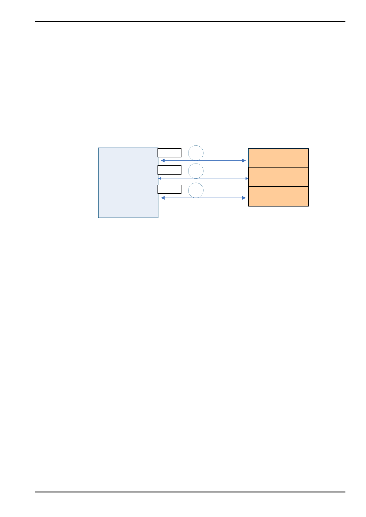
Figure 1-1 System Overview
CPRI
AWS-TRDU
CPRI
CPRI
1 INTRODUCTION
1.1 System Overview
AWS TRDU List10 connect with BBU which made by Alcatel-Lucent. AWS TRDU is transiver
system which is support LTE fuction in AWS freq uency ba nd range.
AWS TRDU is connected by optical c able.
CPRI Interface of one AWS TRDU List10 connect to BBU (LTE)
LTE
BBU
AWS-TRDU
AWS-TRDU
TRDU shelf
5/14 PMC CONFIDENTIAL

AWS TRDU List10 Installation Guide Issue: 1.0.0
Figure 1-2 Equipment Outline
Tower-top
Equipment
OCI Ether net
CPRI
AISG
I2C
DC-48V
OCI Serial(telnet)
1.2 Equipment Outline
BBU
AWS-TRDU
Monitor
① Execute transmit and receive B BU and UL/ DL Digital Signal by optical interfac e
② Enable to maintain TRDU with OCI (On site Configuration Interface) and Personal
Computer.
③ Enable to use Alarm-interface detect function
④ AISG supply and control power function which is connected to tower-top equipment
from TRDU.
⑤ This system support DC -48V power input
⑥ Execute several functions (Status-Control/Tranciver-Control/Mesurement/Failure
-Control…) based on co ntrol messa ge of BBU.
⑦ Enable to download S oftware (Control Software, DSP Firmware、FPGA Data) as
remotely
6/14 PMC CONFIDENTIAL

AWS TRDU List10 Installation Guide Issue: 1.0.0
1.3 Structural Outline
【Structure Outline】
① Thermal method is air‐cooled engine(TRDU has no cooling fan)
② Enable to load next cable (Power Cable/Optical Cable/AISG Cable/ Antenna Cable
/AUX Cable) from Front side of the TRDU.
③ There are LED in front side of the TRDU which can monitoring system status.
7/14 PMC CONFIDENTIAL

AWS TRDU List10 Installation Guide Issue: 1.0.0
No
Item
Content
Remark
1
Input Power
-48V (-37V~-57V)
2 Power Consumption
Less than 650W
3 Weight
Less than 15kg
4 Temperature range
-40~+60℃
5 Humidity range
5~95%
6
Dimension
Width 110 mm
7
Thermal Type
naturally air coole d engine
8 Setting Location
Inside
1.4 Specification
1.4.1 S ystem Specification
Height 355 mm( not include guide rail )
Depth 360 mm
8/14 PMC CONFIDENTIAL

AWS TRDU List10 Installation Guide Issue: 1.0.0
No
Item
Condition/etc
Remark
<
<
Mix mode:1550 nm/1310 nm
<Prim ary port>
<
2.4576 Gbps~6.144 Gbps
<Prim ary port>
<
1.4.2 Opti cal Modul e Specification
Primary port>
Optical Center
1
Length
2 Bit Rate
DL:1550 nm、UL:1310 nm
Secondary port>
1.2288 Gbps~6.1440 Gbps
Secondary port>
Transmission
3
Distance
Maximum 20 km
Secondary port>
Maximum 50m
9/14 PMC CONFIDENTIAL

AWS TRDU List10 Installation Guide Issue: 1.0.0
No
Item
Type
Remark
1
Support Technologies
LTE
2
RF Output Power
67W/Branch×2
3
Downlink RF Freque ncy
2110 MHz –2155 MHz
4 Uplink RF Frequency
1710 MHz –1755 MHz
5 Number of Carrier
LTE :4Carriers×2
1.4.3 AWS TRDU Specification
134W/Branch×1
10/14 PMC CONFIDENTIAL

AWS TRDU List10 Installation Guide Issue: 1.0.0
Figure 2-1 Appearance of the TRDU with connector covers
2 Installing the TRDU
2.1 Appearance
4-φ5.5 holes for Equipment mounting
and Ground Lugs
(There are 2-φ5.5 holes on opposite side)
11/14 PMC CONFIDENTIAL

AWS TRDU List10 Installation Guide Issue: 1.0.0
Figure 2-2 User Interface
Table 2-1 Connectors, LED, Reset button etc.
No.
Connector Name
Connector Type and Comment
2
TX/RX 2
7/16 DIN F
4
TX2 Mon
DIN 1.0/2.3 F
6
AUX RX2
DIN 1.0/2.3 F
SFP Shield Cage
Tyco Electronics 2007198-1
SFP Shield Cage
Tyco Electronics 2007198-1
Amphenol P-FCE17-E2W2SB-FN5-RevB
12
I2C
RJ 45
14
Reset Button
-
(1)
(2)
(5)
(6)
(7)
(8)
(15)
(10)
(11)
(12)
(13)
(9)
(3)
(4)
(14)
2.2 User Interface
1 TX/RX 1 7/16 DIN F
3 TX1 Mon DIN 1.0/2.3 F
5 AUX RX1 DIN 1.0/2.3 F
7 CPRI PRI
8 CPRI SEC
9 ALD Female 8-pin circular connector, per IEC 60130-9
10 DC -48V IN
11 ETH(Ethernet) RJ 45
13 Serial Port 4-pin Firewire socket, per IEEE1394
15 Status LED -
SFP Connector Tyco Electronics 1888247-1
SFP Connector Tyco Electronics 1888247-1
2W2 2-pin D-sub circular connector
12/14 PMC CONFIDENTIAL

AWS TRDU List10 Installation Guide Issue: 1.0.0
Table 2-2 LED Display States
No.
State
Green LED
Yellow LED
Red LED
1
No Power Supplied
Off
Off
Off
2
Initial Power On
Solid
Solid
Solid
3
Normal Operation
Solid
Off
Off
4
Standby
Off
Solid
Off
5
Critical HW Failure
Off
Off
Solid
6
Partial or Non-Critic al Failu re
Solid
Off
Solid
7
Tmporary HW Critical Fault
Off
Off
Flash
8
Slave CPRI Link External Failure
Off
Solid
Solid
9
External Antenna Failure
Solid
Off
Flash
10
Software Download
Off
Flash
Off
11
Background Software Download
Solid
Flash
Off
12
External Power Supply Failure
Flash
Flash
Flash
13
Reset Button
Solid
Solid
Solid
2.3 Status LED
13/14 PMC CONFIDENTIAL

AWS TRDU List10 Installation Guide Issue: 1.0.0
Changes or modifications not expressl y approved b y the party responsibl e for compli ance
could void the user’s authority to operate the equipment.
Properly shielded and grounded cables and connectors must be used for connection to
host computers and / or perip herals in order to mee t FCC emissio n limits.
Data transmission is always initiated b y software, which is the passed down through the
of information to transmit or operational failure.
FCCPart15: This device complies with Part15 of the FCC Rules.
RF approval: This equipment complies with Part 2, Subpart J – Equipment Authorization
WIRELESS COMMUNICATIONS
SERVICES, Subpart 27.53 (h)
3 FCC WARNING
MAC, through the digital and analog baseband, and final ly to the RF chip . Several special
packets are initiated by the MAC. These are the
turn on the RF transmitter, which it then turns off at the end of the
transmitter will be on only while one of the aforem entioned packets is being transmitted. In
other words, this device automa tically disconti nue transmission in case of either absenc e
only ways the digital baseband portion will
packet. Therefore, the
Operation is subject to the condition that thisdevice does not cause harmful interference.
Procedures, of the FCC Rules.
This device complies with Part 27- MISCELLANEOUS
14/14 PMC CONFIDENTIAL
 Loading...