

Document Title
PAGE: 1
700MHz TRDU B12 User Manual
DATE: 11-30-2012
700MHZ B12 TRDU
1.0
DCP-xxxxxx
11-30-2012
Initial Release
D. Fisher
NOTE: APPROVAL ON THIS PAGE SIGNIFIES THE ENTIRE DOCUMENT APPROVED.
USER MANUAL
REV DCO NO. DATE CHANGE INFORMATION AUTHOR
DOCUMENT NO.: 43-G07CRH-48-01B-U-00016 APPROVED BY
PAGE NO.: 1 OF 17
Document Title
PAGE: 2
700MHz TRDU B12 User Manual
DATE: 11-30-2012
1.0 11-30-2012
REVISION HISTORY
DOCUMENT NO.: 43-G07CRH-48-01B-U-00016 TITLE:700MHz TRDU B12 User Manual
Initial release
D.Fisher
Document Title
PAGE: 3
700MHz TRDU B12 User Manual
DATE: 11-30-2012
Table of Contents
1.0 Introduction ...................................................................................................................................................................................... 4
2.0 System Specifications ......................................................................................................................................................................... 5
4.0 Interfaces .......................................................................................................................................................................................... 7
4.1 Connectors ..................................................................................................................................................................................... 7
5.0 Mechanical ........................................................................................................................................................................................ 9
6.0 Photographs ...................................................................................................................................................................................... 10
6.1 Front Panel .................................................................................................................................................................................... 11
6.2 Chassis – Open Faced.................................................................................................................................................................... 12
6.3 RLB and PSM ................................................................................................................................................................................. 13
Conformance Statement ......................................................................................................................................................................... 14
Document Title
PAGE: 4
700MHz TRDU B12 User Manual
DATE: 11-30-2012
1.0 Introduction
MTI’s G07CRH-48-01B is a 2x67W LTE TRDU which has two RF transmitters, two receivers and double duplexer filter. It
is packaged in a single shelf-mounted module and is deployed in CPRI-complian t bas estation networks.
The TRDU features in-house developed dynamic digital power amplifier linearization technology which efficiently
processes LTE transmissions, enabling:
• High PA efficiency, resulting in low power consumption (475 W)
• Low EVM waveform support. Adjustable from <4% to >12%
• Efficient unbalanced power transmissions
Additional features:
• Hardware ready to suppor t 1 LTE carrier with 1.4MHz, 3MHz, 5 MHz and 10MHz bandwidth or up to 3 LTE carriers
with 15MHz maximum bandwidth.
• Low receiver noise figure (2dB), enables the base sta tion OEM to reach exc ellent receiv er sensitivit y. Two Rx chains
support receive diversity, increasing uplink performance even further.
• Two externally pluggabl e SFP sock ets enabling fiel d selectabl e optical interf aces includi ng 1310nm (UL)/ 1550nm(DL)
single-mode single fiber and 850nm multi-mode dual fiber. Electrical interfaces are suppor ted as well
• Software supports Ethernet over CPRI and allows easy implementation of customer specific requirements.
• Supports 2-way MIMO. Two units can be combined to support 4x4 MIMO or 2-wa y MIMO with 4 recei ve branches.
• External AISG interface, I2C interface and a serial port for additional system control and monitoring.
• Extensive Operations and Maintenance f unctionality support ed through flexibl e O&M SW. Self -diagnosis and alarm s
continuously monitoring:
• High MTBF (>375, 000 hour s )
Document Title
PAGE: 5
700MHz TRDU B12 User Manual
DATE: 11-30-2012
Unit Weight
14.5 Kg
DC Power in
-37V to -57VV (Nominal -48Vdc)
Operational Temperature Range
-40°C to +55°C
Storage/Transportation Temperature Range
-55ºC to +70ºC
Enclosure Class
IP20
Safety and Grounding
EN 60950-1, IEC 60950, UL 60950-1
Storage
ETSI EN 300 019-1-1 class 1.2, IEC 60721-3-1
Transportation
ETSI EN 300 019-1-2 class 2.3, IEC 60721-3-2
Operational
ETS 300 019-2-4
Standards Compliance
IEC 68 Series, ETS EN 300 019 Series
MTBF @ 40º C
>375,000 Hours, SR-332
Programmable Frequency Range
Band12: DL Band 729-745MHz, UL Band 699~715MHz
Power Supply Voltage
-48V DC
Total Power Consumption
475W typical
Receive Diversity
2 antenna receive diversity standard
Transmit Diversit y
2 antenna transmit diversity standard
Receiver Noise Figure
2.0 dB nominal, <2.2 dB at max operating temperature
Instantaneous Bandwidth
15 MHz
# of Carriers
3 LTE carrier with maximum 15MHz bandwidth
Transmit Output Power
2x 67W (2x48.26 dBm) at antenna connector
Output Power Accuracy
+/- 0.5 dB
Downlink Modulation
LTE
SEM/ACPR/EVM
As defined in TS 36.104 V8.6.0 or latest
CPRI Rate
Support CPRI rates 1 through 5, hardware ready for rate 6
Optical or electrical Interface
Standard SFP modules, field loadable
2.0 System Specifications
PARAMETER TARGET SPECIFICATIONS
Table 1: MECHANICAL/EN VIR ON MENTAL SPECIF I C ATIONS
Unit Dimensions
360.0 mm by 367.0 mm by110.0 mm=14.53 liter
Table 2: SYSTEM SPECIFICATIONS

Document Title
700MHz TRDU B12 User Manual
DATE: 11-30-2012
PARAMETER
Signals
Connector type
Connection
CPRI
Data/control
SFP sockets
Interface between the RRH and Node B controller
maintenance
the RRH and the antenna
Power Supply Connector
DC Power
D-Sub
Primary power input to the RRH
ALD
AISG
AISG 8-pin
Antenna Line Device
I2C
I2C
RJ45
I2C control interface
TX monitor
RF
DIN 1.0/2.3 female
TX monitor ports
Auxiliary RX I/O port
RF
DIN 1.0/2.3 female
RX monitor and testing ports
Optical/Electrical Connectors: SFP cages
PIN #
PIN Name
Function
Primary
CPRI PRI
Master Fiber LC connector to SFP module
Secondary
CPRI SEC
Slave Fiber LC connector to SFP module
Debug Connector: RJ45
PIN #
PIN Name
Function
1
RJ45 TX+
Ethernet Transmit pair positive
2
RJ45 TX-
Ethernet Transmit pair negative
3
RJ45 RX+
Ethernet Receive pair positive
4
Reserved
Not used
5
Reserved
Not used
6
RJ45 RX-
Ethernet Receive pair negative
7
Reserved
Not used
8
Reserved
Not used
PIN #
PIN Name
Function
TX1/RX1
Transmit Receive
DIN type Transmit/Receive RF port
TX2/RX2
Transmit Receive
DIN type Transmit/Receive RF port
4.0 Interfaces
4.1 Connectors
PAGE: 7
LMT interface Debug RJ45/1394
Transmit/Receive Antenna Connector RF DIN Type female
4.1.1 CPRI Data/Control
4.1.2 Debug Connector
Ethernet interface between the RRH and user
Transmit (Tx) and receive (Rx) the signals between
4.1.3 RF connectors

Document Title
700MHz TRDU B12 User Manual
DATE: 11-30-2012
DC Power Connector: Mini Fit Junior
PIN #
PIN Name
Function
1
+24V
+24V DC supply input
2
+24V RTN
+24V DC supply return
8-pin AISG
Capability
Clamp
1
2
not used
Not used, not connected
3
RS485 B
4
5
RS485 A
6
7
8
N/C
Not used, not connected
8-pin RJ-45 style connector
Capability
Clamp
RRH reports current over CPRI (current
(between 1K and 10Kohm) to ground.
+24V pin 2 (power for
external filter)
Same as Pin 1. Common internal
source for Pin 1 & 2 is acceptable.
3
GND
4
5
I2C_SDA
Serial Data I/O (I2C)
4.7k ohm pull up resistor to 3.3V
6
Pull down through 1kohm (or lower)
resistance to enable 24V on pins 1 & 2.
Using pull-up resistors, pulled up to
3.3V.
4.1.4 DC Power Connector
4.1.5 AISG Connector
PAGE: 8
PIN # Designation
+12 V DC Nominal 1.0 A 1.0 A RRH shall monitor and report current over CPRI.
RS485 GND RS485 ground, isolated from DC Return and Ground
+24V Nominal 850 mA 850 mA RRH monitor and report current over CPRI
DC Return
4.1.6 I2C Connector
PIN # Designation
1
2
+24V_FL_1 *
+24V_FL_2 *
GND
Max Current
Max Current
Current
Current
Additional Notes / Requirements
Description Additional Notes/ Requirements
+24V pin 1 (power for
external filter)
combined with Pin 2) Regulated supply.
Not active until 100ms to 200ms after
Pin 7 is pulled down through resistor
GND
7
8
CTL_24V Control pin for +24V
I2C_SCL Serial Clock (I2C)

Document Title
700MHz TRDU B12 User Manual
DATE: 11-30-2012
5.0 Mechanical
PAGE: 9
Document Title
700MHz TRDU B12 User Manual
DATE: 11-30-2012
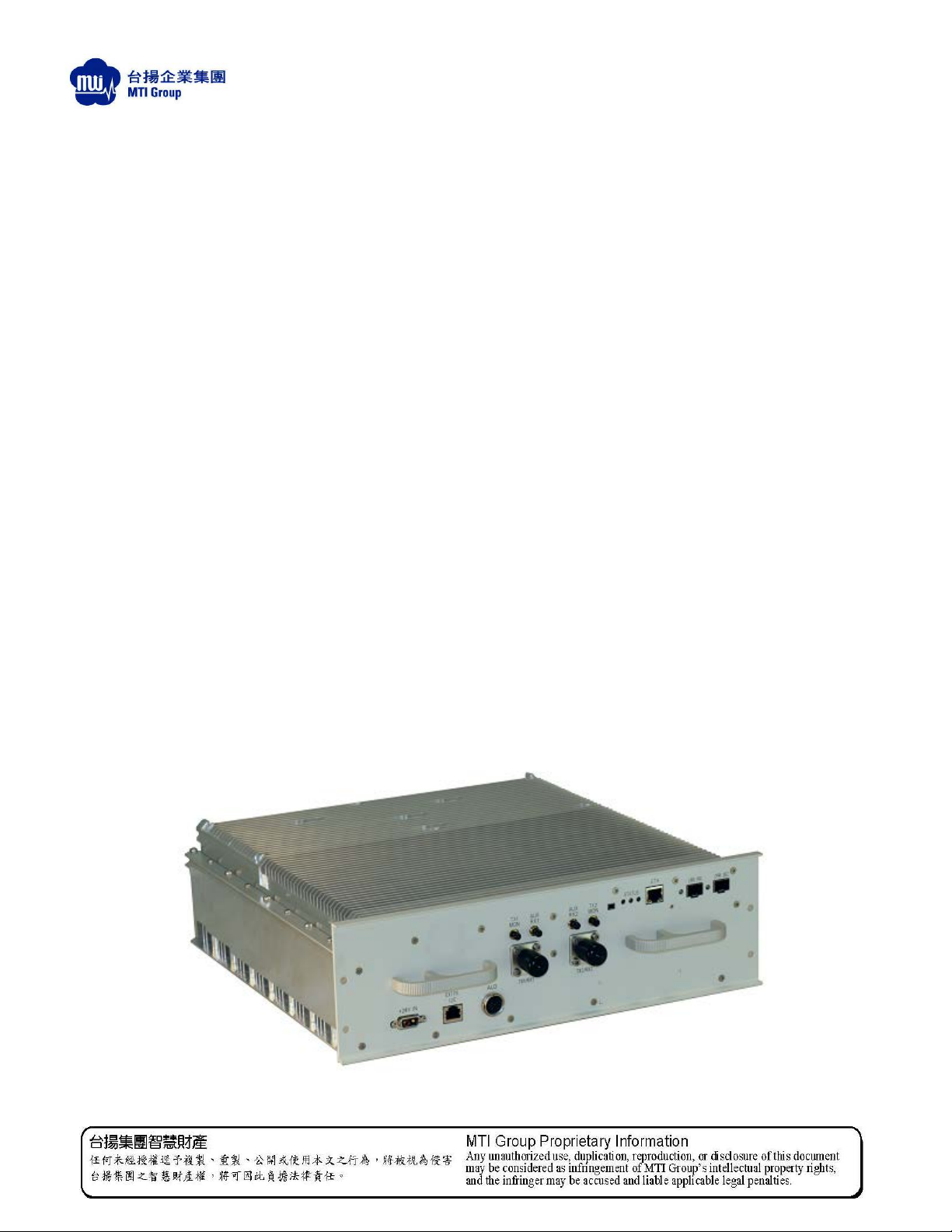
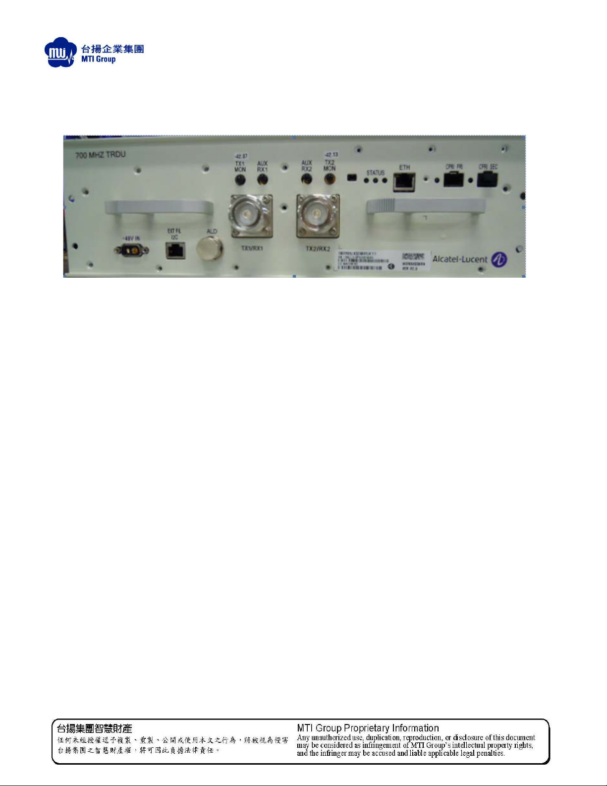
6.0 Photographs
6.1 Front Panel
PAGE: 10

Document Title
700MHz TRDU B12 User Manual
DATE: 11-30-2012
6.2 Chassis – Open Faced
PAGE: 12

Document Title
700MHz TRDU B12 User Manual
DATE: 11-30-2012
6.3 RLB and PSM
PAGE: 13

Product conformance statements Page - 14
United States
....................................................................................................................................................................................................................................
RAFT
D
Indoor applications
This equipment is intended for installation in restricted access locations where access is
controlledorwhere
Access to this equipment is restricted to qualified service personnel only.
Antenna exposure
Antenna installations for the 9412 eNodeB shall be performed in accordance with all
applicable manufacturer’s recommendations, and national laws
ensure correct antenna installation, the antenna installer shall perform all necessary
calculations and/or field measurements to evaluate compliance with applicable national
laws or regulations regarding exposure to electromagnetic fields. The supplier of radio
equipment, the supplier of antenna equipment and the integrator and builder of the site
must provide sufficient information so that the limits of the exclusion zones can be
determined. Any changes to the antenna or other equipment in the transmit path may
require re-evaluation of the exposures to electromagnetic fields.
access
can
be gained by service personnel with a key or tool.
only
and regulations. To
Pursuant to 47 CFR Part 1, Subpart I, subject to the provisions of section 1.1307, all
installations must be evaluated for requirements contained in Table 1, “Limits for
maximum permissible exposure,” in section 1.1310.
Packaging collection and recovery requirements
Countries, states, localities, or other jurisdictions may require that systems be
established for the return and/or collection
other end user, or from the waste stream. Additionally, reuse, recovery, and/or recycling
targets for the return and/or collection of the packaging waste may be established.
For more information regarding collection and recovery of packaging and packaging
waste within specific jurisdictions, please contact the Alcatel-Lucent Services Environmental Health and Safety organization. For installations not performed by
Alcatel-Lucent Technologies, please contact the Alcatel-Lucent Customer Support
Center at:
Technical Support Services, within the United States: +1 630 224 4762, prompt 2
of packaging waste from the consumer, or
....................................................................................................................................................................................................................................
RAFT
D
A-14
Solely for authorized persons having a need to know
Proprietary – Use pursuant to Company instruction
Alcatel-Lucent – Confidential
Issue 1-DRAFT3 April 2009
401-703-614

Product Conformance Statements - United States
Introduction
The statements that follow are the product conformance statements that apply to the
9412
eNodeB
when
deployedinthe
United States.
Federal Communications Commission
Important! Changes or modifications not expressly approved by Alcatel-Lucent,
Inc. could void the user’s authority to operate the equipment.
.
FCC Part 15
This device complies with Part 15 of the FCC Rules. Operation is subject to the
condition that this device does not cause harmful interference.
FCC Part 15 Class B (as marketed)
Important! This equipment has been tested and found to comply with the limits
for a Class B digital device, pursuant to Part 15 of the FCC Rules. These limits are
designed to provide reasonable protection against harmful interference in a
residential installation. This equipment generates, uses, and can radiate radio
frequency energy and, if not installed and used in accordance with the instructions,
may cause harmful interference to radio communications. However, there is no
guarantee that interference will not occur in a particular installation. If this
equipment does cause harmful interference to radio or television reception, which
can be determined by turning the equipment off and on, the user is encouraged to
try to correct the interference by one or more of the following measures:
D
RAFT
• Reorient or relocate the receiving antenna
• Increase the separation between the equipment and receiver

• Connect the equipment into an outlet on a
the receiver is connected
circuit different from that to which
• Consult the dealer or an experienced radio/TV technician for help.
FCC Part 68
RAFT
D
This Part does not applicable
Technical Support Services, within the United States: +1 630 224 4762, prompt 2
RF approval
This equipment complies with Part 2, Subpart J - Equipment Authorization Procedures,
of the FCC Rules.
This device complies with Part 27 - MISCELLANEOUS WIRELESS COMMUNICATIONS
SERVICES, Subpart 27.53 (g)
....................................................................................................................................................................................................................................
RAFT
D
 Loading...