


APPLICANT: Alcatel-Lucent FCC ID: AS5BBTRX-07
Section 2.1033(C)(3)
USERS MANUAL
Alcatel-Lucent Use pursuant to Company Instructions

APPLICANT: Alcatel-Lucent FCC ID: AS5BBTRX-07
USERS MANUAL
SECTION 2.1033(c) (3)
A copy of the installation and operating instructions to be furnished the user. A draft copy of the instructions may
be submitted if the actual document is not available. The actual document shall be furnished to FCC when it
becomes available.
RESPONSE: A copy of
(1) Light Radio Metro outdoor Installation Manual
is attached.
Alcatel-Lucent Use pursuant to Company Instructions

P
RELIMINARY
P
Alcatel-Lucent 9768
lightRadio™ Metro Radio Outdoor V1.0 B13
Installation
3MN-01751-0002-RJZZA
September 2012
Alcatel-Lucent – Proprietary
Use pursuant to applicable
agreements
RELIMINARY

P
P
Legal notice
Alcatel, Lucent, Alcatel-Lucent and the Alcatel-Lucent logo are trademarks of
owners.
The information presented is subject to change without notice. Alcatel-Lucent assumes no responsibility for inaccuracies contained herein.
Copyright © 2012
Contains proprietary/trade secret information which is the property of Alcatel-Lucent and must not be made available to, or copied or used by anyone outside
Alcatel-Lucent without its written authorization.
RELIMINARY
Not to be used or disclosed except in accordance with applicable agreements.
Alcatel-Lucent.
All rights reserved.
Alcatel-Lucent.
All other trademarks are the property of their respective
RELIMINARY

P
P
P
P
About this document
Purpose
.............................................................................................................................................................................................
RELIMINARY
RELIMINARY
Supported systems
Safety information
........................................................................................................................................................................
.............................................................................................................................................................................
1 Safety
Structure of safety
General safety
statements
considerations
...............................................................................................................................................
...............................................................................................................................................
Specific safety hazards and RF Safety Statements
2 Metro Radio Outdoor features
Power
Physical properties
.............................................................................................................................................................................................
...................................................................................................................................................................
3 Installing an 9768 MRO
Procedure 3-1: Installing the 9768 MRO onto a wall or pole ................................................................................... 3-1
A Product conformance statements
RoHS compliance
General safety
Emissions
....................................................................................................................................................................................
AC power supply conformance
....................................................................................................................................................................
...........................................................................................................................................................................
..........................................................................................................................................
B Other statements
Product safety
............................................................................................................................................................................
Glossary
Index
1-1
1-2
........................................................................................................
1-3
2-2
2-3
A-1
A-1
A-1
A-3
B-1
RELIMINARY
RELIMINARY


List of tables
....................................................................................................................................................................................................................................
P
P
RELIMINARY
1 RF safe distances for different power levels
2 AC power system wiring color codes
3
List of major components and subassemb lies
....................................................................................................
................................................................................................................
..................................................................................................
1-2
2-1
3-1
Alcatel-Lucent – Proprietary
Use pursuant to applicable agreements 3MN-01751-0002-RJZZA
September 2012
9768 lR MRO V1.0 B13
RELIMINARY

List of figures
9768 lR MRO V1.0 B13
September 2012
Alcatel-Lucent –
Proprietary
Use pursuant to applicable
agreements
1-1
P
P
P
P
2-1 Form factor
RELIMINARY
2-2 Front view and side view of the drill hole pattern
3-1 Example of 9768 MRO orientation, right-side up
3-2 Pole-mount bracket attachment to a wide pole
3-3 Pole-mount bracket attachment to a small pole
3-4 Wall-mount bracket to pole-mount bracket
..................................................................................................................................................................
.........................................................................................
.........................................................................................
...............................................................................................
..............................................................................................
......................................................................................................
3-5 Upper screws for attachment to wall-mount bracket
3-6 Bracket ears of the wall-mount bracket ........................................................................................................... 3-99
3-7 Lower screws for attachment to wall-mount bracket
.....................................................................................
................................................................................. ...
RELIMINARY
2-3
2-6
3-4
3-5
3-5
3-6
3-9
3-10
RELIMINARY
RELIMINARY
3MN-01751-0002-RJZZA

List of procedures
9768 lR MRO V1.0 B13
September 2012
Alcatel-Lucent –
Proprietary
Use pursuant to applicable
agreements
P
P
3 Installing an 9768 MRO
3-1 Installing the 9768 MRO onto a wall or pole
..................................................................................................
RELIMINARY
3-3
3MN-01751-0002-RJZZA
RELIMINARY


About this document
9768 lR MRO V1.0 B13
September 2012
Alcatel-Lucent –
Proprietary
Use pursuant to applicable
agreements
P
P
Purpose
This document describes how to install the Alcatel-Lucent 9768 lightRadio™ Metro
Radio Outdoor V1.0 B13 (9768 MRO) product.
Supported systems
This document assumes that a continuous stream of connected devices already delivers
secure connectivity to the public network from one or more reachable places in the venue.
With this assumption, the scope of the document is only the 9768 MRO and what is
required to connect it to the network, meet its power needs, and ensure that it can
into reliable service.
Safety information
For your safety, this document contains safety statements. Safety statements are given at
points where risks of damage to personnel, equipment, and operation may exist. Failure to
follow the directions in a safety statement may result in serious consequences.
be placed
RELIMINARY
3MN-01751-0002-RJZZA
RELIMINARY
Safety
9768 lR MRO V1.0 B13
September 2012
Alcatel-Lucent –
Proprietary
Use pursuant to applicable
agreements
1-1
P
P
P
P
1 Safety
RELIMINARY
RELIMINARY
Structure of safety statements
Overview
General structure
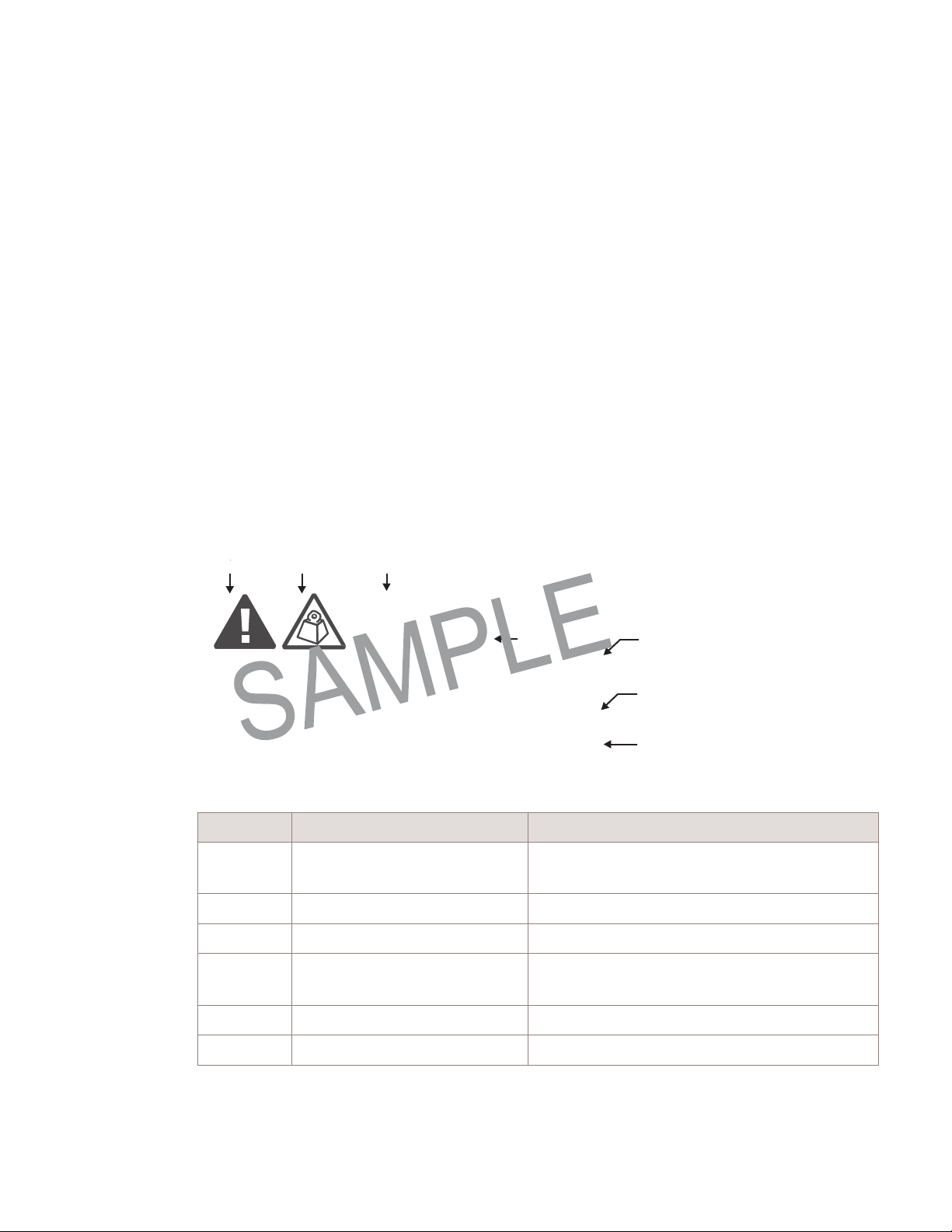
This topic describes the components of safety statements that appear in this document.
Safety statements include the following structural elements:
B C D
CAUTION
Lifting hazard
Lifting this equipment by yourself can result in in jur y
due to the size and weight of the equipment.
Always use three people or a lifting device to transport
and position this equipment. [ABC123]
Item Structure element Purpose
E
F
G
H
RELIMINARY
1 Safety alert symbol Indicates the potential for personal injury
(optional)
2 Safety symbol Indicates hazard type (optional)
3 Signal word Indicates the severity of the hazard
4 Hazard type Describes the source of the risk of damage or
injury
5 Safety message Consequences if protective measures fail
6 Avoidance message Protective measures to take to avoid the hazard
3MN-01751-0002-RJZZA
RELIMINARY

1-2
9768 lR MRO V1.0 B13
September 2012
Alcatel-Lucent –
Proprietary
Use pursuant to applicable
agreements
Safety Structure of safety statements
Item Structure element Purpose
7 Identifier The reference ID of the safety statement
(optional)
Signal words
The signal words identify the hazard severity levels as follows:
Signal word Meaning
DANGER Indicates an extremely hazardous situation which, if not avoided, will
result in death or serious injury.
WARNING Indicates a hazardous situation which, if not avoided, could result in
death or serious injury.
CAUTION Indicates a hazardous situation which, if not avoided, could result in
minor or moderate injury.
NOTICE Indicates a hazardous situation not related to personal injury.
General safety considerations
Shock hazards
Some parts of all electrical installations are energized. Failure to follow safe work
practices and the safety warnings may lead to bodily injury and property damage.
For this reason, only trained and qualified personnel (electrical workers as defined in
IEC 60215 or EN 60215 + A1 or in the National Electrical Code or in ANSI/NFPA No.
10) may install or service the installation.
WARNING
Electric-shock hazard
WARNING
Electric-shock hazard
3MN-01751-0002-RJZZA
There is a danger of electric shock if the grounding system is
You
must comply with the grounding requirements for the grounding system.
inadequate.

P
P
Power
RF safe
RF safe distance from
RF safe distance
RF safe distance
1000 mW
8.8” (22.34 cm)
8.3” (21 cm)
12.4” (31.6 cm)
11.9” (30.3 cm)
500 mW
6.2” (15.8 cm)
5.7” (14.5 cm)
8.8” (22.34 cm)
8.3” (21 cm)
Safety Specific safety hazards
....................................................................................................................................................................................................................................
Specific safety hazards
Human irradiation by RF transmissions
The Federal Communications Commission (FCC) establishes and from time to
revises
guidelines for human exposure to RF electromagnetic fields in the USA. Its Office
of Engineering and Technology then publishes these guidelines in bulletins to allow
companies, such as Alcatel-Lucent, who develop products that transmit non-ionizing RF
waves to calculate safe human exposure distances, based on a corresponding amount of
time spent within those distances.
Safe separation distance
The product complies with RF exposure limits of FCC Part 1.1310 Table 1 (B) Limits for
General Population/Uncontrolled Exposure
The equipment must be installed and operated with a minimum separation distance as
stated in the following power levels and operational modes.
Table 1-1 RF safe distance for different power levels
time
RELIMINARY
input to
antenna
distance from
antenna for
SISO mode
cabinet RADOM for
SISO mode
from antenna
for 2x2 MIMO
mode
from cabinet
RADOM for 2x2
MIMO mode
At greater distances from the 9768 MRO, any duration of exposure is considered safe.
RELIMINARY

...................................................................................................................................................................................................................................
2-1
9768 lR MRO V1.0 B13
September 2012
Alcatel-Lucent –
Proprietary
Use pursuant to applicable
agreements
P
P
2 Metro Radio Outdoor
features
Functional features
Air interface and carrier band
The 9768 MRO is a dual transmit/dual receive path radio supporting frequency division
duplex (FDD) LTE air interface. The 9768 MRO is ideally suited to support dense metro
hot spots, with multiple-input multiple-output (MIMO) 2x2 operation in up to 10 MHz of
Antenna characteristics
bandwidth.
Note: 9768 MRO also supports a single Tx antenna (SIMO).
The 9768 MRO comprises an integrated dual polarized Tx/Rx panel antenna.
RELIMINARY
3MN-01751-0002-RJZZA
•
Frequency of operation 746 MHz - 787 MHz
RELIMINARY

....................................................................................................................................................................................................................................
2-2
Alcatel-Lucent –
Proprietary
Use pursuant to applicable
agreements
9768 lR MRO V1.0 B13
RJZZA
September 2012
Metro Radio Outdoor features
Power
....................................................................................................................................................................................................................................
P
P
Power
Power system
RELIMINARY
The 9768 MRO requires a single phase, three-wire power source to provide nominal
120-V AC/
The following table summarizes the color codes:
Table 2-1 AC power system wiring color codes
Color Function
Black Line
White Neutral
Green Ground / Protective earth (PE)
Power factor
The minimum power factor (ratio of working power to apparent power) is 0.92.
Although this value is above the typical power factor penalty threshold, it is
unlikely to have a true impact on rates for power consumption.
AC frequency from source
The power supply of the 9768 MRO demands frequency of 47 Hz to 63 Hz
from the voltage source, at any allowable level of voltage.
208-V AC (measured at the input), line to neutral.
RELIMINARY
3MN-01751-0002-

Metro Radio Outdoor features
Physical properties
...................................................................................................................................................................................................................................
2-3
9768 lR MRO V1.0 B13
September 2012
Alcatel-Lucent –
Proprietary
Use pursuant to applicable
agreements
P
P
P
P
P
P
....................................................................................................................................................................................................................................
RELIMINARY
Physical properties
Form factor
RELIMINARY
RELIMINARY
Dimensions
The form factor of the 9768 MRO is as shown in Figure 2-1, “Form factor” (p. 2-3).
Figure 2-1 Form factor
The approximate dimensions of the 9768 MRO without its mounting hardware are as follows:
•
17.9 inches (454 mm) high
•
6.8 inches (173 mm) wide
•
7.9 inches (200 mm) deep
•
13 inches (332 mm) deep with its wall-mount bracket
Drill hole pattern
Following is an image providing a front view and side view of the drill hole pattern:
Figure 2-3 Front view and side view of the drill hole pattern
RELIMINARY
RELIMINARY
3MN-01751-0002-RJZZA
RELIMINARY

Metro Radio Outdoor features
Power
....................................................................................................................................................................................................................................
....................................................................................................................................................................................................................................
2-4
Alcatel-Lucent –
Proprietary
Use pursuant to applicable
agreements
9768 lR MRO V1.0 B13
RJZZA
Issue 0.05 September 2012
Measurements are in mm [inches]
.
3MN-01751-0002-

....................................................................................................................................................................................................................................
2-3
9768 lR MRO V1.0 B13
September 2012
Alcatel-Lucent –
Proprietary
Use pursuant to applicable
agreements
Installing an 9768 MRO
Procedure 3-1: Installing the 9768 MRO onto a wall or pole
....................................................................................................................................................................................................................................
201376472
Amplifier, BNJ888, CDY-B13 P1.1
201376480
Radio, BNJ887, NG3e-B13 P1.1
1AF24959AAAA
A conducted emissions chokes)
1AF26285AAAA
B conducted emissions chokes)
3 Installing an 9768 MRO
Table 3-1 List of major components and subassemblies
CC Description
109791186 9768 MRO B13 (700U)
849172283 Antenna, KS24844
849168794 Filter, KS24799 L5
Power Supply Unit, LCC250-12U-4P-401 (w/ Class
Power Supply Unit, LCC250-12U-4P-402 (w/ Class
3MN-01751-0002-RJZZA

....................................................................................................................................................................................................................................
2-4
Alcatel-Lucent –
Proprietary
Use pursuant to applicable
agreements
9768 lR MRO V1.0 B13
RJZZA
Issue 0.05 September 2012
Installing an 9768 MRO
Procedure 3-1: Installing the 9768 MRO onto a wall or pole
....................................................................................................................................................................................................................................
P
P
P
P
RELIMINARY
RELIMINARY
Procedure 3-1: Installing the 9768 MRO onto a wall or pole
Overview
This procedure includes guidelines for fastening the bracket, making the data connection, making the
power connection, and rough-tuning the aim. It does not extend to
bringing the
9768 MRO into operation,
reading the status of the connected 9768 MRO, and optimizing its RF communications.
The 9768 MRO is designed to be installed with the right-side up orientation, as shown in the following
image:
Figure 3-1 Example of 9768 MRO orientation, right-side up
Installing the 9768 MRO
Perform the following steps:
...................................................................................................................................................................................................
1 If this is a pole-mount installation, attach the standard RRH pole-mount hardware to the
pole.
RELIMINARY
RELIMINARY
3MN-01751-0002-

....................................................................................................................................................................................................................................
2-5
9768 lR MRO V1.0 B13
September 2012
Alcatel-Lucent –
Proprietary
Use pursuant to applicable
agreements
Installing an 9768 MRO
Procedure 3-1: Installing the 9768 MRO onto a wall or pole
....................................................................................................................................................................................................................................
P
P
RELIMINARY
The following image shows a pole with a wider diameter (152 mm - 380 mm).
Figure 3-2 Pole-mount bracket attachment to a wide pole
The following image shows a pole with a low diameter (50 mm - 152 mm). A separate
pole-mount kit is available for poles measuring between 50 mm - 152 mm.
Figure 3-3 Pole-mount bracket attachment to a small pole
3MN-01751-0002-RJZZA
RELIMINARY

....................................................................................................................................................................................................................................
2-6
Alcatel-Lucent –
Proprietary
Use pursuant to applicable
agreements
9768 lR MRO V1.0 B13
RJZZA
Issue 0.05 September 2012
Installing an 9768 MRO
Procedure 3-1: Installing the 9768 MRO onto a wall or pole
....................................................................................................................................................................................................................................
P
P
P
P
...................................................................................................................................................................................................
2 Attach the wall-mount bracket
•
to the pole-mount bracket, if this is a pole-mount installation, using M10 hardware
provided with the pole mount kit.
RELIMINARY
RELIMINARY
•
to the venue wall or façade, if this is a wall-mount installation, using M10 or 3/8
hardware.
Figure 3-4 Wall-mount bracket to pole-mount bracket
Figure 3-5 Upper screws for attachment to wall-mount bracket
RELIMINARY
RELIMINARY
...................................................................................................................................................................................................
3 Push the 9768 MRO into the wall-mount bracket so that the top ears of the bracket slide
3MN-01751-0002-

....................................................................................................................................................................................................................................
2-7
9768 lR MRO V1.0 B13
September 2012
Alcatel-Lucent –
Proprietary
Use pursuant to applicable
agreements
Installing an 9768 MRO
Procedure 3-1: Installing the 9768 MRO onto a wall or pole
....................................................................................................................................................................................................................................
into the slots that run along the sides of the back of the 9768 MRO.
...................................................................................................................................................................................................
4 Slide the 9768 MRO downward until the tops of the slots in the mounting bracket ears
meet the screws that you threaded into the side flanges of the 9768 MRO.
3MN-01751-0002-RJZZA

....................................................................................................................................................................................................................................
2-8
Alcatel-Lucent –
Proprietary
Use pursuant to applicable
agreements
9768 lR MRO V1.0 B13
RJZZA
Issue 0.05 September 2012
Installing an 9768 MRO
Procedure 3-1: Installing the 9768 MRO onto a wall or pole
....................................................................................................................................................................................................................................
P
P
RELIMINARY
Figure 3-6 Bracket ears of the wall-mount bracket
...................................................................................................................................................................................................
5 Thread an M6x20 TR30 screw through each of the lower side flange holes
...................................................................................................................................................................................................
6 Tighten all four mounting screws.
3MN-01751-0002-
RELIMINARY

....................................................................................................................................................................................................................................
2-1
9768 lR MRO V1.0 B13
September 2012
Alcatel-Lucent –
Proprietary
Use pursuant to applicable
agreements
....................................................................................................................................................................................................................................
P
P
P
P
Figure 3-7 Lower screws for attachment to wall -mount bracket
RELIMINARY
RELIMINARY
E
...N...D.....O...F......S..T...E..P...
S
.....................................................................................................................................................................
RELIMINARY
3MN-01751-0002-RJZZA
RELIMINARY

...................................................................................................................................................................................................................................
Q.
Issue 0.05 September 2012
P
P
P
P
RELIMINARY
RELIMINARY
Powering up the device
Perform the following steps:
...................................................................................................................................................................................................
1 Test the power from the outlet of the junction box.
...................................................................................................................................................................................................
2 If power to the junction box has been shut off, turn it on.
...................................................................................................................................................................................................
3 Attach the customer-supplied waterproof plug (suitable for the supply voltage,
208-V
...................................................................................................................................................................................................
4
...................................................................................................................................................................................................
AC or
240-V
AC) to the far end.
Plug the power cord into the junction box outlet.
120-V
AC,
5 Begin observing and noting the changes that occur in the LED indications of the 9768
MRO.
RELIMINARY
RELIMINARY
...................................................................................................................................................................................................
6 When a steady-lit green indication has been achieved, inform the commissioning and
integration team that the replacement has been successfully completed.
E
...N...D.....O...F......S..T...E..P...S.....................................................................................................................................................................

A-1
9768 lR MRO V1.0 B13
Issue 0.05 September 2012
Alcatel-Lucent –
Proprietary
Use pursuant to applicable
agreements
P
P
Appendix A: Product
conformance statements
RoHS compliance
Statement of compliance
This product complies with EU RoHS Directive “6 of 6”, including the China version
(Ref E3).
General safety
Statement of compliance
This product complies with CAN/CSA-C22.2
Edition, Information Technology Equipment – Safety, Part 1: General Requirements. This
covers safety requirements in the USA.
No.60950-1-07/UL-60950-1,
RELIMINARY
Second
Emissions
Intentional radiator, statement of compliance
This product meets FCC Part 1.1310, Part 2 and FCC Part 27 requirements.
This product complies with EEC Directive 89/336/EEC for radiated emissions, which
Unintentional radiator, statement of compliance
3MN-01751-0002-RJZZA
references FCC Part 15 Subpart B.
This product complies with FCC Part 15 Subpart B, Class B radiated and power line
conducted emissions limit.
This product complies with CISPR 22 for radiated emissions, Class B. This standard
addresses unintentional radiators.
RELIMINARY

...................................................................................................................................................................................................................................
Q.
Issue 0.05 September 2012
P
P
P
P
Product conformance statements Radiated interference..
Radiated interference
Statement of compliance
RELIMINARY
In accordance with FCC rules 15. 19 this product is labeled as follows “This device
complies with part 15 of the FCC Rules. Operation is subject to the condition that
this device does not cause harmful interference”.
This product complies with FCC Part 15 Subpart B, Class B radiated and power line
conducted emissions limit.
This equipment has been tested and found to comply with the limits for a Class B digital
device, pursuant to Part 15 of the FCC Rules.
These limits are designed to provide reasonable protection against harmful interference
in a residential installation. This equipment generates, uses, and can radiate radio
frequency energy and, if not installed and used in accordance with the instructions, may
cause harmful interference to radio communications. However, there is no guarantee that
interference will not occur in a particular installation. If this equipment does cause
harmful interference to radio or television reception, which can be determined by turning
the equipment off and on, the user is encouraged to try to correct the interference by one
or more of the following measures:
RELIMINARY
•
Reorient or relocate the receiving antenna.
•
Increase the separation between the equipment and receiver.
•
Connect the equipment into an outlet on a circuit different from that to which the
receiver is connected.
•
Consult the dealer or an experienced radio/TV technician for help.
AC power supply conformance
IEC standard, statement of compliance
Telcordia standard, statement of compliance
The AC power supply of this product complies with IEC 60364-1.
The AC power supply of this product complies with Telcordia GR-1089 Section 7.
RELIMINARY
RELIMINARY

Appendix B:
Other statements
9768 lR MRO V1.0 B13
3MN
September 2012
Alcatel-Lucent –
Proprietary
Use pursuant to applicable
agreements
B-1
Product safety
Safety conformance statement
The 9768 MRO is safety certified by [Placeholder].
This Certification is marked on the equipment main nameplate label. Should the local
Authority Having Jurisdiction (AHJ) require prior or additional verification of this
Certification, a Product Certificate of Compliance can be obtained from the specific
Certification Body by the Business/Product Unit Applicant for the product or
contacting Technical Support Services at (630) 224 4762, prompt 2. Any modifications to
this equipment are not permitted without review and official written authorization
specific Certification Body. Unauthorized changes may violate the Product Safety
Certification. Modifications or changes authorized by official CN/CNN are assumed to
have received prior approval from this Lab.
by
from the
Collection and recovery
Eco-environmental statement
Packaging collection and recovery requirements. Countries, states, localities, or other
jurisdictions may require that systems be established for the return and/or collection of
packaging waste from the consumer, or other end user, or from the waste stream.
Additionally, reuse, recovery, and/or recycling targets for the return and/or collection of
the packaging waste may be established. For more information regarding collection and
recovery of packaging and packaging waste within specific jurisdictions, contact the
Alcatel-Lucent Environment, Health and Safety organization or Alcatel-Lucent
Hazardous Waste Center technical support at (888) 539-2783.
...................................................................................................................................................................................................................................
-01751-0002-RJZZA


Glossary
....................................................................................................................................................................................................................................
GL-1
9768 lR MRO V1.0 B13
September 2012
Alcatel-Lucent –
Proprietary
Use pursuant to applicable
agreements
P
P
RELIMINARY
...................................................................................................................................................................................................................................
A AHJ
The agency or authority having
jurisdiction.
Article 100 of the National Electrical Code (NEC) for
the United States defines AHJ with greater specificity, stating that it may be a federal, state, local
government, or individual such as a fire chief, fire marshal, chief of a fire prevention bureau,
labor department or health department, building official or electrical inspector, or others having
statutory authority. In some circumstances, the property owner or his/her agent assumes the roles,
and at government installations, the commanding officer or departmental official may be the AHJ.
...................................................................................................................................................................................................................................
B BBU
Baseband unit, the digital signal processor that connects the MRO to the network and provides the
timing and logic for periodic sync signals. In this context, the BBU is the master, and the MRO is
the slave. Thus, the fiber optic cable from the BBU should be connected to the slave port of the
MRO.
...................................................................................................................................................................................................................................
C CAN/CSA
Canadian Standards Association. See http://www.csa.ca (http://www.csa.ca).
CE Mark
The official logo that substantiates the manufacturer whose product bears it has complied with all
EEC directives that apply. See also EEC directive.
CFR
Code of Federal
Regulations.
Among these regulations, Title 47, “Telecommunication,” conveys
the rules of the FCC companies operating networks in the USA. See also FCC.
CPRI
Common Public Radio Interface. Alcatel-Lucent was one of several major companies who
participated in defining the specification for this interface between the radio (the MRO in this
case) and the radio equipment controller (the BBU in this case). See also BBU.
...................................................................................................................................................................................................................................
D d2U
The BBU system supporting two controller and two modems. See also BBU.
RELIMINARY
3MN-01751-0002-RJZZA

Glossary
....................................................................................................................................................................................................................................
....................................................................................................................................................................................................................................
GL-2
Alcatel-Lucent –
Proprietary
Use pursuant to applicable
agreements
9768 lR MRO V1.0 B13
RJZZA
September 2012
P
P
E EEC directive
A law enacted by the European Union for enforcement by its Common Market. The terms of such
a law have been used as a point of reference against which to compare the intentional RF
emissions of the MRO.
RELIMINARY
EIRP
The equivalent isotropically radiated power. The density of the peak power of a radio in the
direction of its greatest amount of gain. This is typically expressed in dBm, a measure relative to
power out per mW.
ESD
Electrostatic discharge, a hazard that electronic equipment such as the MRO can suffer by way of
exposure to static electricity or proximity to something that has no connection to ground.
...................................................................................................................................................................................................................................
F FCC
Federal Communications Commission. Its Wireless Communications Service (WCS) bureau
regulates, among other services, commercial services in the upper 700-MHz frequency band in
the USA.
FDD
Frequency-division duplexing, a radio indexing system whose transmit and receive signals are on
differing carrier frequencies.
FRU
Field-replaceable unit, a designation connoting that the part can be removed in favor of a new one
when diagnostic exercises seem to have isolated a fault to the part. The overall implication is that,
if those exercises point to either no particular part, then the entire unit should be replaced. In the
case of the MRO, the only FRUs are the SFP port modules (see also SFPs) and the whole MRO
itself.
...................................................................................................................................................................................................................................
G GR
Generic requirements published by Telcordia Technologies. See also Core.
...................................................................................................................................................................................................................................
I IEC
International Electrotechnical Commission. The MRO complies with numerous standards that this
independent body has propagated.
...................................................................................................................................................................................................................................
L LC
A small connector that terminates a fiber optic cable and snaps into its mate.
RELIMINARY
3MN-01751-0002-

....................................................................................................................................................................................................................................
GL-3
9768 lR MRO V1.0 B13
September 2012
Alcatel-Lucent –
Proprietary
Use pursuant to applicable
agreements
P
P
Glossary
....................................................................................................................................................................................................................................
lR
A member of the Alcatel-Lucent lightRadio™ family of wireless products. The MRO belongs to
this family.
LTE
3GPP Long Term Evolution wireless standard for high-speed data devices. Evolution implies that
the air interface has evolved from GSM/UMTS standards to an OFDM-based air interface that
realizes peak rates of 300 Mbps downlink and 75 Mbps uplink at less than 5 ms latency. See also
3GPP and OFDM.
...................................................................................................................................................................................................................................
O OFDM
Orthogonal frequency-division multiplexing, the multi-carrier modulation scheme that overcomes
many commonly experienced wireless communications problems, such as multipath and signal
attenuation.
...................................................................................................................................................................................................................................
P PDCP
Packet Data Convergence Protocol, which provides security to both the air interface and the fiber
optic interface of the MRO by compressing and decompressing the IP headers, as specified in the
UMTS protocol stack.
...................................................................................................................................................................................................................................
R Radiall
The proprietary name of an enterprise that produces components for device interconnections.
These components include the R2CT weatherized connector kit by which the MRO installer
retrofits the LC fiber optic connector on the backhaul cable to the SFP port module of the MRO.
The proper name of this company is Radiall USA, Inc. See also SFP.
RoHS
The Restriction of Hazardous Substances Directive, a law enacted by the European Union for
enforcement by its Common Market in order to restrict six particular materials in electrical and
electronic products. These materials are the elements lead, mercury, and cambium, and three
compounds. More broadly, the standard QC 080000 propagates RoHS specifications throughout
the world and thus impacts the choice of regions, nations, and states and provinces selected to
regulate the same substances. The MRO is fully compliant with the RoHS directive.
RRH
Remote RF head consisting of a radio, a receive filter, a transmit amplifier, and a CPRI link to a
BBU. The MRO is an RRH. See also BBU and CPRI.
...................................................................................................................................................................................................................................
S SFP
A small form-factor pluggable module, which serves as the connector in the MRO for the fiber
RELIMINARY
RELIMINARY
3MN-01751-0002-RJZZA

Glossary
....................................................................................................................................................................................................................................
....................................................................................................................................................................................................................................
GL-4
Alcatel-Lucent –
Proprietary
Use pursuant to applicable
agreements
9768 lR MRO V1.0 B13
RJZZA
September 2012
optic
interfac
e to the
BBU.
This
module
is an
FRU.
See also
BBU
and
FRU.
3MN-01751-0002-

....................................................................................................................................................................................................................................
GL-5
9768 lR MRO V1.0 B13
September 2012
Alcatel-Lucent –
Proprietary
Use pursuant to applicable
agreements
P
P
SIMO
Single input, multiple output. Its transmitter function uses a one antenna, and its receiver function
uses two. This scheme reduces the instance of multipath and fading, in particular. Antonyms are
MISO (multiple input, single output) and MIMO (multiple input, multiple output).
...................................................................................................................................................................................................................................
RELIMINARY
W W-CDMA
Wideband code division multiplex air interface, used by UMTS-FDD. See also FDD.
RELIMINARY
3MN-01751-0002-RJZZA


....................................................................................................................................................................................................................................
IN-1
9768 lR MRO V1.0 B13
September 2012
Alcatel-Lucent –
Proprietary
Use pursuant to applicable
agreements
P
P
Index
Numerics
6 of 6 (EU RoHS Directive), A-1
9926 BBU
interface to, 2-2
................................................................................................
A AC power supply, A-3
Amperage, 2-2
Ancillary equipment
optional, 2-8
required, 2-8
Antenna
characteristics, 2-1
Assumptions, xi
Audience for this document, xi
Authority having jurisdiction (AHJ)
definition of, GL-1
when demanding verification, B-1
AWG of power feed wire, 2-2
Azimuth, 2-4
................................................................................................
B Backhaul, 2-8
Band of operation, 2-1
Beam width, 2-1
Bracket
pole-mount, 2-8
wall-mount, 2-4
................................................................................................
C CAN/CSA-C22.2, A-1
Carrier band, 2-1
China version of RoHS Directive, A-1
CISPR 22, A-1
Collection and recovery, B-1
Conducted immunity, A-2
Conducted spurious emissions, A-1
Conformance statements, A-1
Conventions used in this document, xiii
CPRI interface, 2-2
CPRI Line Bit Rate, 2-8
................................................................................................
D Data interface, 2-8
Depth, 2-4
Dimensions, 2-4
Directive 89/336, A-1
Distance
human from 9768 MRO in operation, 1-3
Documents
conventions used, xiii
ordering, xiii
other related, xiii
support for use of, xiii
RELIMINARY
RELIMINARY
3MN-01751-0002-RJZZA

....................................................................................................................................................................................................................................
IN-2
Alcatel-Lucent –
Proprietary
Use pursuant to applicable
agreements
9768 lR MRO V1.0 B13
RJZZA
September 2012
Index
P
P
....................................................................................................................................................................................................................................
................................................................................................
E Eco-environmental statement, B-1
EEC Directive 89/336, A-1
Elevation
RELIMINARY
beam, 2-4
Emissions
intentionally radiated, A-1
unintentionally radiated, A-1
Environment and waste support contact information, B-1
ESD immunity, A-2
EU RoHS Directive, A-1
................................................................................................
F Fasteners
all, 3-2
FCC guidelines for exposure to RF radiation, 1-3
FCC Part 15, A-1, A-2
Fiber optic cable, 2-8, 2-8
Form factor, 2-3
Frequency band, 2-1
Fronthaul interface, 2-8
FRU, 2-2
FullAXS connector, 2-8
................................................................................................
G Gain, 2-1
GR-1089, A-2, A-3
GR-1089-2628, A-1
................................................................................................
H Handoff to another technology, 2-1
Height, 2-4
................................................................................................
I IEC 50529, A-3
IEC 60364-1, A-3
IEC 61000-4-3, A-2
IEC 61000-4-6, A-2
Immunity to radiated interference, A-2, A-2
Information Technology Equipment – Safety, A-1
Installation procedure, 3-3
Intentionally radiated emissions, A-1
Interface air,
2-1 data,
2-1
Isotropic reference gain, 2-1
................................................................................................
M Mounting procedure, 3-3
................................................................................................
O Online customer support (OLCS), xiii
Ordering documents, xiii
................................................................................................
P Parts for installation, 3-1
PDCP, 2-1
Pole-mount bracket
kits, 2-8
Ports, spurious emissions, A-1
Power
consumption, 2-2
factor, 2-3
frequency, 2-3
transmitted, 2-1
Power supply, A-3
Product Safety Certification, B-1
Protection Code IP20, A-3
Protocol, 2-1
................................................................................................
R Radiated emissions, A-1, A-1
Radiated interference, A-2
Recovery, B-1
RELIMINARY
3MN-01751-0002-

....................................................................................................................................................................................................................................
IN-3
9768 lR MRO V1.0 B13
September 2012
Alcatel-Lucent –
Proprietary
Use pursuant to applicable
agreements
P
P
Index
RELIMINARY
....................................................................................................................................................................................................................................
Recycling, B-1
T Technical supp ort pe r
Reference gain, 2-1
country, xiii
RoHS Directive, A-1
................................................................................................
S Safety
certification, B-1
general requirements, A-1
Security
through software, 2-1
Security cover, 2-8
SFP module, 2-2, 2-8
Solar shield, 2-7
Solids, ingress, A-3
Speed of data link, 2-8
Spurious emissions, A-1
Statements of compliance, A-1
U Unintentionally radiated emissions, A-1
Uninterruptible power, 2-2
................................................................................................
V Voltage, 2-2
................................................................................................
W Wall-mount bracket
services, contact information, B-1
Technology, 2-1
Temperature range, 2-7
Tilt adjustment range, 2-4
Timing, 2-2
Torx drivers required, 3-2
................................................................................................
adjustability for azimuth and elevation, 2-4
Support
depth, 2-4
environment and waste issues, contact information,
B-1
services, contact information, B-1
technical, xiii
using documents, xiii
Synchronization, 2-2
................................................................................................
screws, 2-4
weight, 2-4
Waste, B-1
Wattage, 2-2
Weight, 2-4
Width, 2-4
3MN-01751-0002-RJZZA
RELIMINARY
 Loading...