

Page 1

APPLICANT: Alcatel-Lucent EXHIBIT 3 FCC ID: AS5BBTRX-18
EXHIBIT 3
Section 2.1033 (c)(3) INSTALLATION AND OPERATING INSTRUCTIONS
A copy of the installation and operating instructions to be furnished to the user. A draft copy of the
instructions may be submitted if the actual document is not available. The actual document shall be
furnished to the FCC when it becomes available.
Response
A copy of Alcatel-Lucent 9768 Metro Radio Outdoor B4 User Manual is attached to this exhibit.
Page 1 of 1
Page 2

Proprietary Use pursuant to Company instruction
Title page
Alcatel-Lucent 9768
Metro Radio Outdoor B4
User Manual
3MN-MRO-AWS-IMOP
Issue 1 | February 2014
Alcatel-Lucent – Internal
Proprietary – Use pursuant to Company instruction
Page 3

Proprietary Use pursuant to Company instruction
Legal notice
Legal notice
Alcatel, Lucent, Alcatel-Lucent and the Alcatel-Lucent logo are trademarks of Alcatel-Lucent. All other trademarks are the property of their respective
owners.
The information presented is subject to change without notice. Alcatel-Lucent assumes no responsibility for inaccuracies contained herein.
Copyright © 2014 Alcatel-Lucent. All rights reserved.
Contains proprietary/trade secret information which is the property of Alcatel-Lucent and must not be made available to, or copied or used by anyone outside
Alcatel-Lucent without its written authorization.
Proprietary – Use pursuant to Company instruction
Alcatel-Lucent – Internal
Page 4

Contents
About this document
Purpose ............................................................................................................................................................................................. xixi
Reason for reissue
Intended audience
Supported systems
How to use this document
Safety information
Conventions used
Related information
How to order
How to comment
1 Safety
Structure of safety statements
General safety considerations
........................................................................................................................................................................ xixi
......................................................................................................................................................................... xixi
........................................................................................................................................................................ xixi
......................................................................................................................................................... xixi
........................................................................................................................................................................ xixi
........................................................................................................................................................................ xiixii
.................................................................................................................................................................... xiixii
................................................................................................................................................................................. xiixii
......................................................................................................................................................................... xiixii
............................................................................................................................................... 1-11-1
............................................................................................................................................... 1-31-3
Specific safety hazards
............................................................................................................................................................ 1-41-4
2 Metro Radio Outdoor features
Functional features
Power
............................................................................................................................................................................................. 2-22-2
Physical properties
................................................................................................................................................................... 2-12-1
................................................................................................................................................................... 2-32-3
3 Installing an 9768 MRO B4
Components and subassemblies
Procedure 3-1: Installing the 9768 MRO B4 onto a wall or pole
....................................................................................................................................................................................................................................
Alcatel-Lucent 9768 MRO
3MN-MRO-AWS-IMOP
Issue 1 February 2014
.......................................................................................................................................... 3-13-1
............................................................................ 3-23-2
Alcatel-Lucent – Internal
Proprietary – Use pursuant to Company instruction
iii
Page 5

Contents
....................................................................................................................................................................................................................................
A Product conformance statements
Glossary
Index
Overview
..................................................................................................................................................................................... A-1A-1
United States compliance
Introduction
Federal Communications Commission
Product safety conformance statements
Antenna exposure statements
................................................................................................................................................................................ A-2A-2
............................................................................................................................ A-3A-3
.......................................................................................................................... A-4A-4
.............................................................................................................................................. A-5A-5
FDA/IEC optical transmitter product compliance statements
Eco-environmental statements
............................................................................................................................................ A-7A-7
................................................................................. A-6A-6
....................................................................................................................................................................................................................................
iv
Proprietary – Use pursuant to Company instruction
Alcatel-Lucent – Internal
Alcatel-Lucent 9768 MRO
3MN-MRO-AWS-IMOP
Issue 1 February 2014
Page 6

List of tables
1 Terminology .................................................................................................................................................................. xiixii
2-1 AC power system wiring color codes ................................................................................................................ 2-22-2
2-2 DC power system wiring color codes ................................................................................................................ 2-22-2
3-1 LED interpretations ................................................................................................................................................ 3-223-22
....................................................................................................................................................................................................................................
Alcatel-Lucent 9768 MRO
3MN-MRO-AWS-IMOP
Issue 1 February 2014
Proprietary – Use pursuant to Company instruction
Alcatel-Lucent – Internal
v
Page 7

List of tables
....................................................................................................................................................................................................................................
....................................................................................................................................................................................................................................
vi
Proprietary – Use pursuant to Company instruction
Alcatel-Lucent – Internal
Alcatel-Lucent 9768 MRO
3MN-MRO-AWS-IMOP
Issue 1 February 2014
Page 8

List of figures
2-1 Form factor .................................................................................................................................................................. 2-32-3
2-2 Drill hole pattern for right side up orientation ................................................................................................ 2-42-4
2-3 Drill hole pattern for upside down orientation ................................................................................................ 2-52-5
3-1 Example of 9768 MRO B4 orientations ............................................................................................................ 3-23-2
3-2 Pole-mount bracket attachment to a large pole ............................................................................................... 3-33-3
3-3 Pole-mount bracket attachment to a small pole .............................................................................................. 3-33-3
3-4 Wall-mount bracket ................................................................................................................................................... 3-43-4
3-5 Fixed wall-mount bracket ....................................................................................................................................... 3-43-4
3-6 Security cover rear attachment ............................................................................................................................. 3-53-5
3-7 Upper screws for attachment to wall-mount bracket .................................................................................... 3-63-6
3-8 Bracket ears of the wall-mount bracket ............................................................................................................. 3-73-7
3-9 Lower screws for attachment to wall-mount bracket ................................................................................... 3-83-8
3-10 RF connectors ............................................................................................................................................................. 3-93-9
3-11 FullAXS cable, connector components separated ....................................................................................... 3-113-11
3-12 Bottom of the 9768 MRO .................................................................................................................................... 3-113-11
3-13 CPRI-S SFP cage, uncovered .............................................................................................................................. 3-113-11
3-14 FullAXS cable, connector components separated ....................................................................................... 3-123-12
3-15 CPRI-S SFP port, exposed ................................................................................................................................... 3-123-12
3-16 CPRI-S SFP port, LC connected ....................................................................................................................... 3-123-12
3-17 FullAXS cable, inner connector body in place ............................................................................................. 3-133-13
3-18 FullAXS cable, connected, and watertight .................................................................................................... 3-133-13
3-19 9768 MRO B4 ground connection points ...................................................................................................... 3-143-14
3-20 Double hole lug ........................................................................................................................................................ 3-153-15
....................................................................................................................................................................................................................................
Alcatel-Lucent 9768 MRO
3MN-MRO-AWS-IMOP
Issue 1 February 2014
Proprietary – Use pursuant to Company instruction
Alcatel-Lucent – Internal
vii
Page 9

List of figures
....................................................................................................................................................................................................................................
3-21 Power connector components ............................................................................................................................. 3-163-16
3-22 Power connector in the connector boot ........................................................................................................... 3-173-17
3-23 Connector boot over the connector ................................................................................................................... 3-183-18
3-24 Power connector ...................................................................................................................................................... 3-183-18
3-25 Security cover front attachment ......................................................................................................................... 3-213-21
....................................................................................................................................................................................................................................
viii
Proprietary – Use pursuant to Company instruction
Alcatel-Lucent – Internal
Alcatel-Lucent 9768 MRO
3MN-MRO-AWS-IMOP
Issue 1 February 2014
Page 10

List of procedures
3 Installing an 9768 MRO B4
3-1
Installing the 9768 MRO B4 onto a wall or pole ........................................................................................... 3-23-2
....................................................................................................................................................................................................................................
Alcatel-Lucent 9768 MRO
3MN-MRO-AWS-IMOP
Issue 1 February 2014
Proprietary – Use pursuant to Company instruction
Alcatel-Lucent – Internal
ix
Page 11

List of procedures
....................................................................................................................................................................................................................................
....................................................................................................................................................................................................................................
x
Proprietary – Use pursuant to Company instruction
Alcatel-Lucent – Internal
Alcatel-Lucent 9768 MRO
3MN-MRO-AWS-IMOP
Issue 1 February 2014
Page 12

Aboutthis documentAbout this document
Purpose
The purpose of this document is to provide hardware installation instructions for
Alcatel-Lucent 9768 Metro Radio Outdoor (9768 MRO) B4.
Reason for reissue
The reissue reasons are:
Issue number Issue Date Reason for reissue
1 February 2014 Standard
Intended audience
The audience for this document is Installation personnel.
Supported systems
This document assumes that a continuous stream of connected devices already delivers
secure connectivity to the public network from one or more reachable places in the venue.
With this assumption, the scope of the document is only the 9768 MRO and what is
required to connect it to the network, meet its power needs, and ensure that it can be
placed into reliable service.
How to use this document
Start with the first chapter and work through the manual to the end. Once you have done
this, you will have carried out the hardware installation completely and in the proper
sequence.
Safety information
For your safety, this document contains safety statements. Safety statements are given at
points where risks of damage to personnel, equipment, and operation may exist. Failure to
follow the directions in a safety statement may result in serious consequences.
...................................................................................................................................................................................................................................
Alcatel-Lucent 9768 MRO
3MN-MRO-AWS-IMOP
Issue 1 February 2014
Proprietary – Use pursuant to Company instruction
Alcatel-Lucent – Internal
xi
Page 13

About this document
....................................................................................................................................................................................................................................
Conventions used
Vocabulary conventions
The following vocabulary conventions are also used when referring to Alcatel-Lucent
products:
Table 1 Terminology
Term Description/Meaning
9768 MRO B4 Refers to Alcatel-Lucent 9768 Metro Radio Outdoor B4 or
Alcatel-Lucent 9768 MRO B4.
Alcatel-Lucent 9768
Metro Radio Outdoor
9768 MRO Refers to Alcatel-Lucent 9768 Metro Radio Outdoor or
Related information
Not Applicable.
How to order
Not Applicable.
How to comment
To comment on this document, go to the Online Comment Form (http://infodoc.alcatel-
lucent.com/comments/
(comments@alcatel-lucent.com).
Refers to 9768 MRO B4.
Alcatel-Lucent 9768 MRO.
) or e-mail your comments to the Comments Hotline
....................................................................................................................................................................................................................................
xii
Proprietary – Use pursuant to Company instruction
Alcatel-Lucent – Internal
Alcatel-Lucent 9768 MRO
3MN-MRO-AWS-IMOP
Issue 1 February 2014
Page 14
1 1Safety
Structure of safety statements
Overview
This topic describes the components of safety statements that appear in this document.
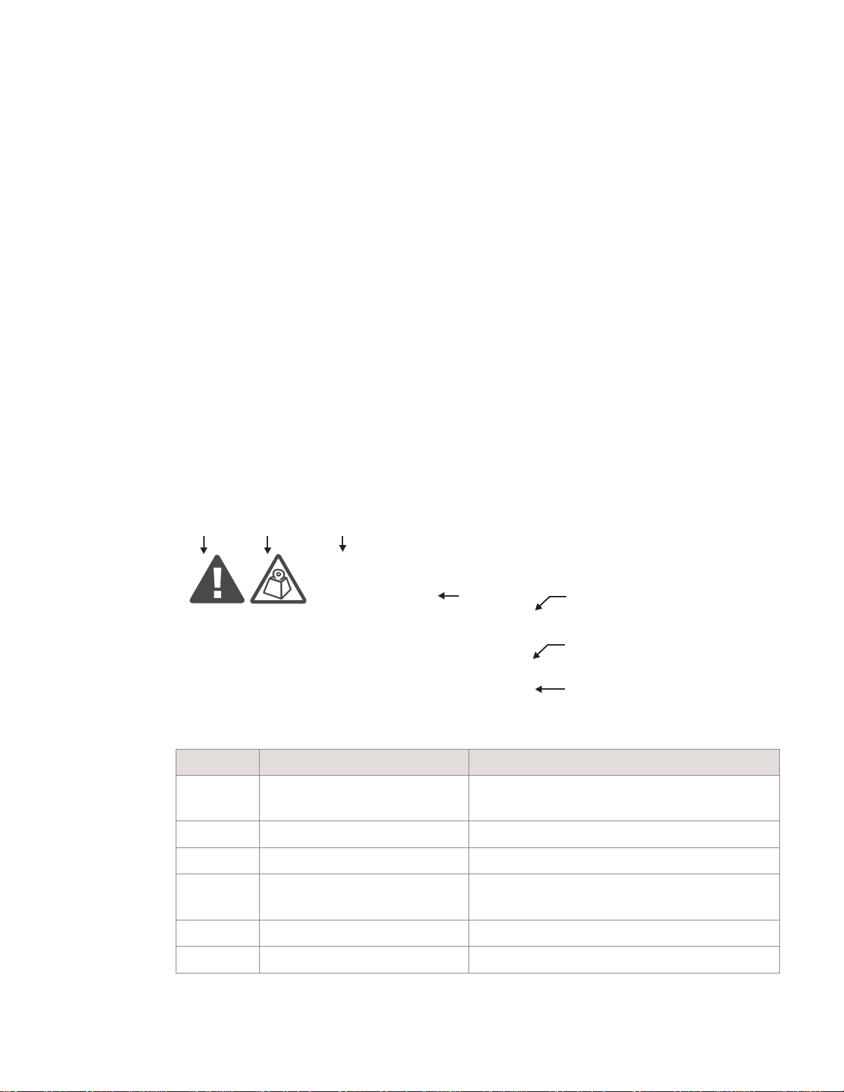
General structure
Safety statements include the following structural elements:
BC D
CAUTION
Lifting hazard
Lifting this equipment by yourself can result in injury
due to the size and weight of the equipment.
Always use three people or a lifting device to transport
and position this equipment. [ABC123]
SAMPLE
Item Structure element Purpose
1 Safety alert symbol Indicates the potential for personal injury
2 Safety symbol Indicates hazard type (optional)
3 Signal word Indicates the severity of the hazard
4 Hazard type Describes the source of the risk of damage or
E
(optional)
injury
F
G
H
5 Safety message Consequences if protective measures fail
6 Avoidance message Protective measures to take to avoid the hazard
...................................................................................................................................................................................................................................
Alcatel-Lucent 9768 MRO
3MN-MRO-AWS-IMOP
Issue 1 February 2014
Proprietary – Use pursuant to Company instruction
Alcatel-Lucent – Internal
1-1
Page 15

Safety Structure of safety statements
....................................................................................................................................................................................................................................
Item Structure element Purpose
7 Identifier The reference ID of the safety statement
(optional)
Signal words
The signal words identify the hazard severity levels as follows:
Signal word Meaning
DANGER Indicates an extremely hazardous situation which, if not avoided, will
result in death or serious injury.
WARNING Indicates a hazardous situation which, if not avoided, could result in
death or serious injury.
CAUTION Indicates a hazardous situation which, if not avoided, could result in
minor or moderate injury.
NOTICE Indicates a hazardous situation not related to personal injury.
....................................................................................................................................................................................................................................
1-2
Proprietary – Use pursuant to Company instruction
Alcatel-Lucent – Internal
Alcatel-Lucent 9768 MRO
3MN-MRO-AWS-IMOP
Issue 1 February 2014
Page 16
Safety General safety considerations
....................................................................................................................................................................................................................................
General safety considerations
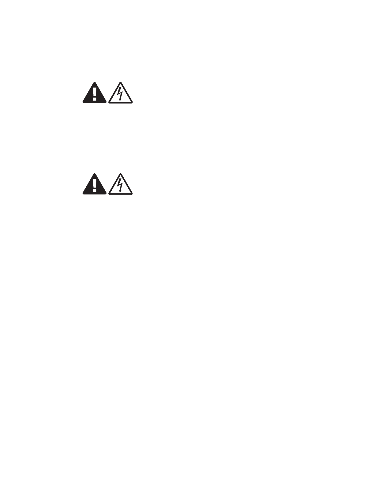
Shock hazards
WARNING
Electric-shock hazard
Some parts of all electrical installations are energized. Failure to follow safe work
practices and the safety warnings may lead to bodily injury and property damage.
For this reason, only trained and qualified personnel (electrical workers as defined in
IEC 60215 or EN 60215 + A1 or in the National Electrical Code or in ANSI/NFPA No.
10) may install or service the installation.
WARNING
Electric-shock hazard
There is a danger of electric shock if the grounding system is inadequate.
You must comply with the grounding requirements for the grounding system.
....................................................................................................................................................................................................................................
Alcatel-Lucent 9768 MRO
3MN-MRO-AWS-IMOP
Issue 1 February 2014
Proprietary – Use pursuant to Company instruction
Alcatel-Lucent – Internal
1-3
Page 17

Safety Specific safety hazards
....................................................................................................................................................................................................................................
Specific safety hazards
Human irradiation by RF transmissions
The Federal Communications Commission (FCC) establishes and from time to time
revises guidelines for human exposure to RF electromagnetic fields in the USA. Its Office
of Engineering and Technology then publishes these guidelines in bulletins to allow
companies, such as Alcatel-Lucent, who develop products that transmit non-ionizing RF
waves to calculate safe human exposure distances, based on a corresponding amount of
time spent within those distances.
Safe separation distance
The product with antennas equipped shall comply with RF exposure limits of FCC Part
1.1310 Table 1 (B) Limits for General Population/Uncontrolled Exposure.
The equipment must be installed and operated with a minimum separation distance,
determined by RF field evaluation, between the radiating antennas and nearby persons.
Any changes to the antenna or other equipment in the transmit path may require
re-evaluation of the exposures to electromagnetic fields.
....................................................................................................................................................................................................................................
1-4
Proprietary – Use pursuant to Company instruction
Alcatel-Lucent – Internal
Alcatel-Lucent 9768 MRO
3MN-MRO-AWS-IMOP
Issue 1 February 2014
Page 18

2 2Metro Radio Outdoor
features
Functional features
Air interface and carrier band
The 9768 MRO B4 is a dual transmit/dual receive path radio supporting frequency
division duplex (FDD) LTE air interface. The 9768 MRO B4 is ideally suited to support
dense metro hot spots, with multiple-input multiple-output (MIMO) 2x2 operation in up
to 20 MHz of bandwidth.
Note: 9768 MRO B4 also supports a single Tx antenna (SIMO).
...................................................................................................................................................................................................................................
Alcatel-Lucent 9768 MRO
3MN-MRO-AWS-IMOP
Issue 1 February 2014
Proprietary – Use pursuant to Company instruction
Alcatel-Lucent – Internal
2-1
Page 19

Metro Radio Outdoor features Power
....................................................................................................................................................................................................................................
Power
AC power system
The 9768 MRO B4 requires a single phase, three-wire power source to provide nominal
120 -V AC, 208 -V AC, or 220 -V AC (measured at the input), line to neutral.
The following table summarizes the AC power system wiring color codes:
Table 2-1 AC power system wiring color codes
Color Connector pin assignment Function
Brown Pin 1 Line
Blue Pin 2 Neutral
Green/Yellow Pin 3 Ground/protective earth (PE)
N/C Pin 4 N/C
Power factor
The minimum power factor (ratio of working power to apparent power) is 0.92. Although
this value is above the typical power factor penalty threshold, it is unlikely to have a true
impact on rates for power consumption.
AC frequency from source
The power supply of the 9768 MRO B4 accepts frequencies ranging from 47 Hz to 63 Hz
from the voltage source, at any allowable level of voltage.
DC power system
The 9768 MRO B4 requires a -48 V DC input.
The following table summarizes the DC power system wiring color codes:
Table 2-2 DC power system wiring color codes
Color Connector pin assignment Function
N/C Pin 1 N/C
White Pin 2 Return
N/C Pin 3 N/C
Black Pin 4 -48 V DC
....................................................................................................................................................................................................................................
2-2
Proprietary – Use pursuant to Company instruction
Alcatel-Lucent – Internal
Alcatel-Lucent 9768 MRO
3MN-MRO-AWS-IMOP
Issue 1 February 2014
Page 20

Metro Radio Outdoor features Physical properties
....................................................................................................................................................................................................................................
Physical properties
Form factor
The form factor of the 9768 MRO B4 is as shown below.
Figure 2-1 Form factor
Dimensions
The approximate dimensions of the 9768 MRO B4 without its mounting hardware is as
follows:
• 17.9 inches (454 mm) high
• 6.8 inches (173 mm) wide
• 6.2 inches (158 mm) deep
• 7.8 inches (198 mm) deep with its wall-mount bracket
....................................................................................................................................................................................................................................
Alcatel-Lucent 9768 MRO
3MN-MRO-AWS-IMOP
Issue 1 February 2014
Proprietary – Use pursuant to Company instruction
Alcatel-Lucent – Internal
2-3
Page 21

Metro Radio Outdoor features Physical properties
....................................................................................................................................................................................................................................
Drill hole pattern
The following image provides different views of the drill hole pattern for mounting the
9768 MRO B4 in a right-side up position:
Figure 2-2 Drill hole pattern for right side up orientation
Measurements are in mm [inches]
....................................................................................................................................................................................................................................
2-4
Proprietary – Use pursuant to Company instruction
Alcatel-Lucent – Internal
Alcatel-Lucent 9768 MRO
3MN-MRO-AWS-IMOP
Issue 1 February 2014
Page 22

Metro Radio Outdoor features Physical properties
....................................................................................................................................................................................................................................
The following image provides different views of the drill hole pattern for mounting the
9768 MRO B4 in an upside down position:
Figure 2-3 Drill hole pattern for upside down orientation
Measurements are in mm [inches]
Note: Mounting the 9768 MRO B4 upside down is recommended only for
installations where the 9768 MRO B4 will not be exposed to the weather elements.
....................................................................................................................................................................................................................................
Alcatel-Lucent 9768 MRO
3MN-MRO-AWS-IMOP
Issue 1 February 2014
Proprietary – Use pursuant to Company instruction
Alcatel-Lucent – Internal
2-5
Page 23

Metro Radio Outdoor features Physical properties
....................................................................................................................................................................................................................................
....................................................................................................................................................................................................................................
2-6
Proprietary – Use pursuant to Company instruction
Alcatel-Lucent – Internal
Alcatel-Lucent 9768 MRO
3MN-MRO-AWS-IMOP
Issue 1 February 2014
Page 24

3 3Installing an 9768 MRO B4
Components and subassemblies
List of major components and subassemblies
CC Description
109803106
109809806
849178934 Filter, KS24799 L5
201386596 Amplifier, BNJ893, CDY-B4
201386620 Radio, BNJ895, NG3e-B4
270056567 Power Supply Unit, DC
1AF24959AAAA Power Supply Unit, AC
9768 MRO B4 DC
9768 MRO B4 AC
...................................................................................................................................................................................................................................
Alcatel-Lucent 9768 MRO
3MN-MRO-AWS-IMOP
Issue 1 February 2014
Proprietary – Use pursuant to Company instruction
Alcatel-Lucent – Internal
3-1
Page 25

Installing an 9768 MRO B4 Procedure 3-1: Installing the 9768 MRO B4 onto a wall or
....................................................................................................................................................................................................................................
pole
Procedure 3-1: Installing the 9768 MRO B4 onto a wall or pole
Overview
This procedure includes guidelines for fastening the bracket, making the data connection
and making the power connection. It does not extend to bringing the 9768 MRO B4 into
operation, reading the status of the connected 9768 MRO, and optimizing its RF
communications.
The Alcatel-Lucent 9768 MRO is designed to be primarily installed in the right-side up
orientation, but it can also be installed in an upside down position, as shown in the
following image:
Figure 3-1 Example of 9768 MRO B4 orientations
Installing the 9768 MRO B4
Note: Save all the protective caps and connector covers in case the unit needs to be
returned later.
Perform the following steps:
...................................................................................................................................................................................................
If this is a pole-mount installation, attach the standard RRH pole-mount hardware to the
1
pole.
....................................................................................................................................................................................................................................
3-2
Proprietary – Use pursuant to Company instruction
Alcatel-Lucent – Internal
Alcatel-Lucent 9768 MRO
3MN-MRO-AWS-IMOP
Issue 1 February 2014
Page 26

Installing an 9768 MRO B4 Procedure 3-1: Installing the 9768 MRO B4 onto a wall or
....................................................................................................................................................................................................................................
pole
The following image shows a large pole kit (152 mm - 380 mm).
Figure 3-2 Pole-mount bracket attachment to a large pole
The following image shows a small pole kit (50 mm - 152 mm).
Figure 3-3 Pole-mount bracket attachment to a small pole
...................................................................................................................................................................................................
Attach the wall-mount bracket
2
• to the pole-mount bracket, if this is a pole-mount installation, using M10 hardware
provided with the pole mount kit.
• to the venue wall or façade, if this is a wall-mount installation, using 3/8 inch (M10)
or 1/4 inch (M6) hardware.
....................................................................................................................................................................................................................................
Alcatel-Lucent 9768 MRO
3MN-MRO-AWS-IMOP
Issue 1 February 2014
Proprietary – Use pursuant to Company instruction
Alcatel-Lucent – Internal
3-3
Page 27

Installing an 9768 MRO B4 Procedure 3-1: Installing the 9768 MRO B4 onto a wall or
....................................................................................................................................................................................................................................
pole
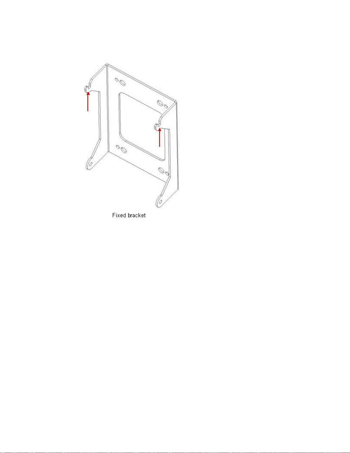
Figure 3-4 Wall-mount bracket
Wall-mount bracket
Wall-mount bracket
on a large pole
Figure 3-5 Fixed wall-mount bracket
Wall-mount bracket
on a small pole
Rear view
...................................................................................................................................................................................................
If this 9768 MRO B4 includes the optional interface security cover, attach the rear half of
3
Front view
the cover to the 9768 MRO B4 enclosure using two-M3x8 TR10 screws.
....................................................................................................................................................................................................................................
3-4
Proprietary – Use pursuant to Company instruction
Alcatel-Lucent – Internal
Alcatel-Lucent 9768 MRO
3MN-MRO-AWS-IMOP
Issue 1 February 2014
Page 28

Installing an 9768 MRO B4 Procedure 3-1: Installing the 9768 MRO B4 onto a wall or
....................................................................................................................................................................................................................................
pole
The following image is a preliminary view of the security cover:
Figure 3-6 Security cover rear attachment
...................................................................................................................................................................................................
Thread two M6x20 TR30 screws into the upper holes on the left and right side of the
4
9768 MRO, irrespective of the 9768 MRO B4 orientation (right side up or upside down),
as show in the following image:
....................................................................................................................................................................................................................................
Alcatel-Lucent 9768 MRO
3MN-MRO-AWS-IMOP
Issue 1 February 2014
Proprietary – Use pursuant to Company instruction
Alcatel-Lucent – Internal
3-5
Page 29

Installing an 9768 MRO B4 Procedure 3-1: Installing the 9768 MRO B4 onto a wall or
....................................................................................................................................................................................................................................
pole
Figure 3-7 Upper screws for attachment to wall-mount bracket
Right side up orientation
...................................................................................................................................................................................................
Place the 9768 MRO B4 onto the wall-mount bracket so that the top ears of the bracket
5
Upside down orientation
slide into the slots that run along the sides of the back of the 9768 MRO B4.
...................................................................................................................................................................................................
Slide the 9768 MRO B4 downward until the tops of the slots in the mounting bracket ears
6
meet the screws that you threaded into the side flanges of the 9768 MRO B4.
....................................................................................................................................................................................................................................
3-6
Proprietary – Use pursuant to Company instruction
Alcatel-Lucent – Internal
Alcatel-Lucent 9768 MRO
3MN-MRO-AWS-IMOP
Issue 1 February 2014
Page 30
Installing an 9768 MRO B4 Procedure 3-1: Installing the 9768 MRO B4 onto a wall or
....................................................................................................................................................................................................................................
pole
Figure 3-8 Bracket ears of the wall-mount bracket
...................................................................................................................................................................................................
Thread an M6x20 TR30 screw through each of the lower side flange holes
7
...................................................................................................................................................................................................
Tighten all four mounting screws, torque to 4.5 Nm (3.3 lb ft).
8
....................................................................................................................................................................................................................................
Alcatel-Lucent 9768 MRO
3MN-MRO-AWS-IMOP
Issue 1 February 2014
Proprietary – Use pursuant to Company instruction
Alcatel-Lucent – Internal
3-7
Page 31

Installing an 9768 MRO B4 Procedure 3-1: Installing the 9768 MRO B4 onto a wall or
....................................................................................................................................................................................................................................
pole
Figure 3-9 Lower screws for attachment to wall-mount bracket
Right side up orientation
E ND OF STEPS
...................................................................................................................................................................................................
Upside down orientation
....................................................................................................................................................................................................................................
3-8
Proprietary – Use pursuant to Company instruction
Alcatel-Lucent – Internal
Alcatel-Lucent 9768 MRO
3MN-MRO-AWS-IMOP
Issue 1 February 2014
Page 32

Installing an 9768 MRO B4 Procedure 3-1: Installing the 9768 MRO B4 onto a wall or
....................................................................................................................................................................................................................................
pole
Installing RF antenna cables for 9768 MRO B4
Perform the following steps:
...................................................................................................................................................................................................
Connect TxRx1 and TxRx2 antenna cables to the 9768 MRO B4. The 9768 MRO B4 uses
1
a 4.1/9.5 miniDIN RF connectors.
Figure 3-10 RF connectors
...................................................................................................................................................................................................
Torque the miniDIN connectors to 10 Nm (7.5 ft lb).
2
...................................................................................................................................................................................................
Locate the surge protector within reach of the RF jumper cable from 9768 MRO B4.
3
Note: See instructions that comes with the surge protection kit for more information.
...................................................................................................................................................................................................
Mount the surge protector to a wall or panel using the bulkhead nut provided with the
4
protector.
...................................................................................................................................................................................................
Attach the 6 AWG ground cable (wire provided with the surge protector kit) to the
5
protector body using the M8 hardware.
...................................................................................................................................................................................................
Attach the other end of the ground wire to the site grounding system.
6
....................................................................................................................................................................................................................................
Alcatel-Lucent 9768 MRO
3MN-MRO-AWS-IMOP
Issue 1 February 2014
Proprietary – Use pursuant to Company instruction
Alcatel-Lucent – Internal
3-9
Page 33

Installing an 9768 MRO B4 Procedure 3-1: Installing the 9768 MRO B4 onto a wall or
....................................................................................................................................................................................................................................
pole
Appropriate hardware may need to be provided by the customer to attach the ground
wire to the site grounding system.
...................................................................................................................................................................................................
Attach the DIN 7/16 connector of the RF jumper cable from the 9768 MRO B4 to one
7
side of the surge protector. Torque the DIN 7/16 connection to 30 Nm (22 lb ft).
...................................................................................................................................................................................................
Attach the customer provided antenna cable to the DIN 7/16 -F side of surge protector.
8
Torque the DIN 7/16 connection to 30 Nm (22 lb ft).
E ND OF STEPS
...................................................................................................................................................................................................
Installing fiber cables
Perform the following steps:
...................................................................................................................................................................................................
Route the fiber cable between the Alcatel-Lucent 9768 Metro Radio Outdoor (9768
1
MRO) and the Alcatel-Lucent 9926 Base Band Unit.(9926 BBU). The FullAXS cable
components are described in
separated” (p. 3-11)
Figure 3-11 FullAXS cable, connector components separated
.
Figure 3-11, “FullAXS cable, connector components
....................................................................................................................................................................................................................................
3-10
Proprietary – Use pursuant to Company instruction
Alcatel-Lucent – Internal
Alcatel-Lucent 9768 MRO
3MN-MRO-AWS-IMOP
Issue 1 February 2014
Page 34

Installing an 9768 MRO B4 Procedure 3-1: Installing the 9768 MRO B4 onto a wall or
....................................................................................................................................................................................................................................
pole
Legend:
1 Outer connector body
2 Inner connector body
3 LC connector
...................................................................................................................................................................................................
Twist and remove the cap from the CPRI-S SFP cage in the bottom of the 9768 MRO B4.
2
Figure 3-12 Bottom of the 9768 MRO
Figure 3-13 CPRI-S SFP cage, uncovered
...................................................................................................................................................................................................
Install the SFP module into the 9768 MRO B4.
3
...................................................................................................................................................................................................
On the fiber cable assembly, slide the outer connector body and inner connector body
4
away from the LC connector.
....................................................................................................................................................................................................................................
Alcatel-Lucent 9768 MRO
3MN-MRO-AWS-IMOP
Issue 1 February 2014
Proprietary – Use pursuant to Company instruction
Alcatel-Lucent – Internal
3-11
Page 35

Installing an 9768 MRO B4 Procedure 3-1: Installing the 9768 MRO B4 onto a wall or
....................................................................................................................................................................................................................................
pole
Figure 3-14 FullAXS cable, connector components separated
...................................................................................................................................................................................................
Connect the LC connector on the cable to the SFP module in the 9768 MRO B4.
5
Figure 3-15 CPRI-S SFP port, exposed
Figure 3-16 CPRI-S SFP port, LC connected
....................................................................................................................................................................................................................................
3-12
Proprietary – Use pursuant to Company instruction
Alcatel-Lucent – Internal
Alcatel-Lucent 9768 MRO
3MN-MRO-AWS-IMOP
Issue 1 February 2014
Page 36

Installing an 9768 MRO B4 Procedure 3-1: Installing the 9768 MRO B4 onto a wall or
....................................................................................................................................................................................................................................
...................................................................................................................................................................................................
Slide the inner connector body over the LC connector until it engages the bulkhead half
6
pole
of the FullAXS connector on the 9768 MRO B4.
Figure 3-17 FullAXS cable, inner connector body in place
...................................................................................................................................................................................................
Slide the outer connector body upward to the bulkhead and twist it clockwise, to lock in
7
place and provide a watertight seal.
Figure 3-18 FullAXS cable, connected, and watertight
...................................................................................................................................................................................................
Gently apply twisting pressure to ensure that the cover for the unused (CPRI-M) cage in
8
the bulkhead is still snug in place.
E ND OF STEPS
...................................................................................................................................................................................................
....................................................................................................................................................................................................................................
Alcatel-Lucent 9768 MRO
3MN-MRO-AWS-IMOP
Issue 1 February 2014
Proprietary – Use pursuant to Company instruction
Alcatel-Lucent – Internal
3-13
Page 37

Installing an 9768 MRO B4 Procedure 3-1: Installing the 9768 MRO B4 onto a wall or
....................................................................................................................................................................................................................................
pole
Connecting the ground cable
Perform the following steps to connect the ground cable to the 9768 MRO B4:
...................................................................................................................................................................................................
The following figures show the ground connection 9768 MRO B4 points:
1
Figure 3-19 9768 MRO B4 ground connection points
9768 MRO B4
Note: For AC powered 9768 MRO B4s, the primary ground is through the AC power
line. The external chassis ground is used only if the site requires a dedicated chassis
ground.
...................................................................................................................................................................................................
Crimp the double hole lug on to the ground cable.
2
....................................................................................................................................................................................................................................
3-14
Proprietary – Use pursuant to Company instruction
Alcatel-Lucent – Internal
Alcatel-Lucent 9768 MRO
3MN-MRO-AWS-IMOP
Issue 1 February 2014
Page 38

Installing an 9768 MRO B4 Procedure 3-1: Installing the 9768 MRO B4 onto a wall or
....................................................................................................................................................................................................................................
pole
The following image shows a long barrel double hole crimp lug:
Figure 3-20 Double hole lug
Long barrel double hole crimp lug
(1/4” hole, ¾” spacing)
...................................................................................................................................................................................................
Attach the ground cable to the 9768 MRO B4 chassis using the M6 hardware provided in
3
the ground kit (M6x16 screw, lock washer, plain washer).
Clean the contact surface area and use an antioxidant to avoid oxidation. Torque the M6
fasteners to 4.5 Nm (3.3 lb ft).
...................................................................................................................................................................................................
Route and attach the ground wire to the site ground system. An extra double hole crimp
4
lug, included in the ground kit, may be used if appropriate or the customer can provide
the necessary components to attach the ground wire to the site ground.
Clean the contact surface area and use an antioxidant to avoid oxidation.
E ND OF STEPS
...................................................................................................................................................................................................
Connecting the power connector
CAUTION
Electric-shock hazard
There is a danger of electric shock when the power cord is energized.
The connection/disconnection of the power cord to the 9768 MRO must be done only with
the power cord de-energized. De-energize the far end of the power cord from the power
source prior to disconnection at the 9768 MRO end.
....................................................................................................................................................................................................................................
Alcatel-Lucent 9768 MRO
3MN-MRO-AWS-IMOP
Issue 1 February 2014
Proprietary – Use pursuant to Company instruction
Alcatel-Lucent – Internal
3-15
Page 39
Installing an 9768 MRO B4 Procedure 3-1: Installing the 9768 MRO B4 onto a wall or
....................................................................................................................................................................................................................................
pole
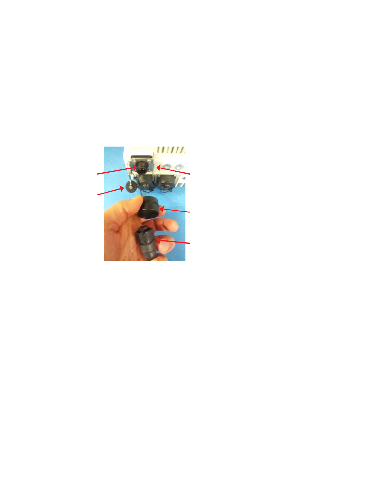
The power connector is equipped with a twist-off weather protection cap. The connector
also has a connector boot and bracket that must be installed over the power cord. The boot
and bracket prevent accidental disconnection of the power from the 9768 MRO while the
power cord is powered. Before connecting, ensure safe and appropriate disconnection of
power from the 9768 MRO.
Perform the following steps to connect the power connector to the 9768 MRO B4.
...................................................................................................................................................................................................
Remove the connector cap by twisting counterclockwise.
1
Figure 3-21 Power connector components
Power
Power
Connector
Connector
Cap
Cap
Bracket
Bracket
Boot
Boot
Power
Power
Cable
Cable
...................................................................................................................................................................................................
Slide the power connector through the connector boot.
2
....................................................................................................................................................................................................................................
3-16
Proprietary – Use pursuant to Company instruction
Alcatel-Lucent – Internal
Alcatel-Lucent 9768 MRO
3MN-MRO-AWS-IMOP
Issue 1 February 2014
Page 40

Installing an 9768 MRO B4 Procedure 3-1: Installing the 9768 MRO B4 onto a wall or
....................................................................................................................................................................................................................................
pole
Figure 3-22 Power connector in the connector boot
...................................................................................................................................................................................................
Twist on the power cord connector onto the 9768 MRO B4.
3
...................................................................................................................................................................................................
Slide the connector boot over the connector.
4
....................................................................................................................................................................................................................................
Alcatel-Lucent 9768 MRO
3MN-MRO-AWS-IMOP
Issue 1 February 2014
Proprietary – Use pursuant to Company instruction
Alcatel-Lucent – Internal
3-17
Page 41

Installing an 9768 MRO B4 Procedure 3-1: Installing the 9768 MRO B4 onto a wall or
....................................................................................................................................................................................................................................
pole
Figure 3-23 Connector boot over the connector
...................................................................................................................................................................................................
Secure the connector boot to the bracket using the cable tie provided with the power
5
cable.
Figure 3-24 Power connector
E ND OF STEPS
...................................................................................................................................................................................................
....................................................................................................................................................................................................................................
3-18
Proprietary – Use pursuant to Company instruction
Alcatel-Lucent – Internal
Alcatel-Lucent 9768 MRO
3MN-MRO-AWS-IMOP
Issue 1 February 2014
Page 42

Installing an 9768 MRO B4 Procedure 3-1: Installing the 9768 MRO B4 onto a wall or
....................................................................................................................................................................................................................................
pole
Installing the AC power cable
There are two possible options while installing the AC power cable - using a connector or
hardwire the power cord.
Perform the following steps if your using a connector:
...................................................................................................................................................................................................
To terminate the unterminated end of the AC power cable, ensure that the plug used is
1
suitable to the environment of use. For example, in an uncontrolled outdoor environment,
use a waterproof plug that supports the supply voltage (120-V AC, 208-V AC, or 240-V
AC).
The cable may be cut down to length if the provided length of 14.7 ft (4.5 m) is more than
required. The plug must be provided by the customer.
...................................................................................................................................................................................................
Do not connect the far end of the power cord to the AC receptacle outlet or any other
2
power source until it is ready to turn on the 9768 MRO B4.
E ND OF STEPS
...................................................................................................................................................................................................
Hardwiring the power cord
Perform the following steps to hardwire the power cord:
...................................................................................................................................................................................................
The AC power cord is 14.7 ft (4.5 m) long. Locate the AC junction box within reach of
1
the AC power cord.
Ensure suitable drip loops can be maintained at, both, the 9768 MRO B4 and the junction
box.
...................................................................................................................................................................................................
Route the AC power from the source to the junction box per acceptable local codes.
2
...................................................................................................................................................................................................
Hardwire the power cord to the power source. If a local disconnect switch or circuit
3
breaker is desired, install one in the junction box.
E ND OF STEPS
...................................................................................................................................................................................................
....................................................................................................................................................................................................................................
Alcatel-Lucent 9768 MRO
3MN-MRO-AWS-IMOP
Issue 1 February 2014
Proprietary – Use pursuant to Company instruction
Alcatel-Lucent – Internal
3-19
Page 43

Installing an 9768 MRO B4 Procedure 3-1: Installing the 9768 MRO B4 onto a wall or
....................................................................................................................................................................................................................................
pole
Installing the DC power cable
Perform the following steps to install the DC power cable:
...................................................................................................................................................................................................
The DC power cord is 14.7 ft (4.5 m) long. Locate the DC junction box within reach of
1
the DC power cord. Ensure suitable drip loops can be maintained at, both, the 9768 MRO
B4 and the junction box.
...................................................................................................................................................................................................
Route the DC power from the source to the junction box per acceptable local codes.
2
...................................................................................................................................................................................................
Hardwire the power cord to the power source. If a local disconnect switch or circuit
3
breaker is desired, install one in the junction box.
E ND OF STEPS
...................................................................................................................................................................................................
Fixing the optional security cover
...................................................................................................................................................................................................
If this 9768 MRO B4 includes the optional interface security cover, attach the front half
1
of the cover to the rear half using two-M3x8 TR10 screws.
....................................................................................................................................................................................................................................
3-20
Proprietary – Use pursuant to Company instruction
Alcatel-Lucent – Internal
Alcatel-Lucent 9768 MRO
3MN-MRO-AWS-IMOP
Issue 1 February 2014
Page 44

Installing an 9768 MRO B4 Procedure 3-1: Installing the 9768 MRO B4 onto a wall or
pole
....................................................................................................................................................................................................................................
The following image is a preliminary view of the security cover:
Figure 3-25 Security cover front attachment
E ND OF STEPS
...................................................................................................................................................................................................
....................................................................................................................................................................................................................................
Alcatel-Lucent 9768 MRO
3MN-MRO-AWS-IMOP
Issue 1 February 2014
Proprietary – Use pursuant to Company instruction
Alcatel-Lucent – Internal
3-21
Page 45

Installing an 9768 MRO B4 Procedure 3-1: Installing the 9768 MRO B4 onto a wall or
....................................................................................................................................................................................................................................
pole
Powering up the device
Perform the following steps:
...................................................................................................................................................................................................
Test the power at the power source.
1
...................................................................................................................................................................................................
If power to the receptacle outlet has been shut off, turn it on.
2
...................................................................................................................................................................................................
3
CAUTION
RF hazard
Near immediately after the model is powered, it can begin to transmit RF signals and thus
becomes a potential hazard of human irradiation from that RF. Nonionizing radiation of
this kind may damage human tissue or cause other health problems, even at doses far
below those that produce perceptible heating.
For more information on the safe separation distance, see
(p. 1-4)
.
“Safe separation distance”
Plug the power cord into the power source.
...................................................................................................................................................................................................
Begin observing and noting the changes that occur in the LED indications of the 9768
4
MRO.
On the bottom of the Alcatel-Lucent 9768 MRO, a single visible LED provides local
diagnostic indications. The LED indications have specific meanings, as defined in the
following table:
Table 3-1 LED interpretations
If the LED is... then the indication is that...
not lit at all the 9768 MRO is not powered.
steady-lit green the 9768 MRO is powered, its RF functions are enabled, and its links with the
blinking green the 9768 MRO is not transmitting.
steady-lit yellow the slave link between this 9768 MRO and the next 9768 MRO in a
9926 d2U Base Band Unit are active.
daisy-chained configuration has a fault. Where a daisy chain is not
implemented (as in the initial release of this product, which does not support
daisy chaining), this LED condition will not be seen.
blinking yellow a download of firmware is occurring.
....................................................................................................................................................................................................................................
3-22
Proprietary – Use pursuant to Company instruction
Alcatel-Lucent – Internal
Alcatel-Lucent 9768 MRO
3MN-MRO-AWS-IMOP
Issue 1 February 2014
Page 46

Installing an 9768 MRO B4 Procedure 3-1: Installing the 9768 MRO B4 onto a wall or
....................................................................................................................................................................................................................................
pole
Table 3-1 LED interpretations (continued)
If the LED is... then the indication is that...
steady-lit red either
• the system is in its initial power-up state
• a major non-recoverable hardware failure in the 9768 MRO is occurring,
and it must be replaced.
blinking red a recoverable error is occurring. For example, the temperature is out of range
...................................................................................................................................................................................................
When a steady-lit green indication has been achieved, inform the commissioning and
5
or an antenna fault exists.
integration team that the installation has been successfully completed.
E ND OF STEPS
...................................................................................................................................................................................................
....................................................................................................................................................................................................................................
Alcatel-Lucent 9768 MRO
3MN-MRO-AWS-IMOP
Issue 1 February 2014
Proprietary – Use pursuant to Company instruction
Alcatel-Lucent – Internal
3-23
Page 47

Installing an 9768 MRO B4 Procedure 3-1: Installing the 9768 MRO B4 onto a wall or
pole
....................................................................................................................................................................................................................................
....................................................................................................................................................................................................................................
3-24
Proprietary – Use pursuant to Company instruction
Alcatel-Lucent – Internal
Alcatel-Lucent 9768 MRO
3MN-MRO-AWS-IMOP
Issue 1 February 2014
Page 48

Appendix A: Product
conformance statements
Overview
Purpose
This section presents the product conformance statements that apply to the Alcatel-Lucent
9768 Metro Radio Outdoor access point equipment.
The statements that are required are determined primarily by national or multi-national
regulations. However, in some regions, contract terms determine which statements are
required.
The presence of the statement indicates that the product does comply with that statement
wherever it is required to do so.
Contents
United States compliance A-2
Federal Communications Commission A-3
Product safety conformance statements A-4
Antenna exposure statements A-5
FDA/IEC optical transmitter product compliance statements A-6
Eco-environmental statements A-7
...................................................................................................................................................................................................................................
Alcatel-Lucent 9768 MRO
3MN-MRO-AWS-IMOP
Issue 1 February 2014
Proprietary – Use pursuant to Company instruction
Alcatel-Lucent – Internal
A-1
Page 49

Product conformance statements
United States compliance
....................................................................................................................................................................................................................................
Introduction
United States compliance
Introduction
Purpose
The statements that follow are the product conformance statements that apply to the
Alcatel-Lucent 9768 Metro Radio Outdoor when deployed in the United States.
Contents
Federal Communications Commission A-3
Product safety conformance statements A-4
Antenna exposure statements A-5
FDA/IEC optical transmitter product compliance statements A-6
Eco-environmental statements A-7
....................................................................................................................................................................................................................................
A-2
Proprietary – Use pursuant to Company instruction
Alcatel-Lucent – Internal
Alcatel-Lucent 9768 MRO
3MN-MRO-AWS-IMOP
Issue 1 February 2014
Page 50

Product conformance statements
United States compliance
....................................................................................................................................................................................................................................
Federal Communications Commission
Federal Communications Commission
Federal Communications Commission
Important! Changes or modifications not expressly approved by Alcatel-Lucent, Inc.
could void the user’s authority to operate the equipment.
This device complies with Part 15 of the 47 CFR FCC Rules. Operation is subject to the
following two conditions:
(1) this device may not cause harmful interference, and
(2) this device must accept any interference received, including interference that may
cause undesired operation.
47 CFR FCC Part 15 Class B
Note: This equipment has been tested and found to comply with the limits for a Class
B digital device, pursuant to Part 15 of the 47 CFR FCC Rules.
These limits are designed to provide reasonable protection against harmful
interference in a residential installation.
RF approval
This equipment generates, uses, and can radiate radio frequency energy and, if not
installed and used in accordance with the instructions, may cause harmful interference
to radio communications. However, there is no guarantee that interference will not
occur in a particular installation.
If this equipment does cause harmful interference to radio or television reception,
which can be determined by turning the equipment off and on, the user is encouraged
to try to correct the interference by one or more of the following measures:
• Reorient or relocate the receiving antenna
• Increase the separation between the equipment and receiver
• Connect the equipment into an outlet on a circuit different from that to which the
receiver is connected
• Consult the dealer or an experienced radio/TV technician for help.
This equipment complies with Part 2, Subpart J - Equipment Authorization Procedures, of
the FCC Rules.
This equipment complies with Part 27 - MISCELLANEOUS WIRELESS
COMMUNICATIONS SERVICES.
....................................................................................................................................................................................................................................
Alcatel-Lucent 9768 MRO
3MN-MRO-AWS-IMOP
Issue 1 February 2014
Proprietary – Use pursuant to Company instruction
Alcatel-Lucent – Internal
A-3
Page 51

Product conformance statements
United States compliance
....................................................................................................................................................................................................................................
Product safety conformance statements
Product safety conformance statements
Product safety conformance
This equipment is Safety Certified for the United States of America by a Nationally
Recognized Test Laboratory (NRTL) accredited by the US Department of Labor,
Occupational Safety and Health Administration (OSHA), such as UL, CSA, or others.
The product bears this certification mark of this certification laboratory on its main
nameplate label. Should the local authority having jurisdiction (AHJ) require prior or
additional verification of this certification, a product certificate of compliance can be
obtained from the specific certification laboratory by the business/product unit Applicant
for the product or by contacting Alcatel-Lucent Technical Support. See the Alcatel-Lucent
Support web site ( (
Any modifications to this equipment are not permitted without review and official written
authorization from the specific Certification Body. Unauthorized changes may violate the
Product Safety Certification. Modifications or changes authorized by official CN/CNN
are assumed to have received prior approval from this Lab.
http://www.alcatel-lucent.com/support/)) for contact information.
....................................................................................................................................................................................................................................
A-4
Proprietary – Use pursuant to Company instruction
Alcatel-Lucent – Internal
Alcatel-Lucent 9768 MRO
3MN-MRO-AWS-IMOP
Issue 1 February 2014
Page 52

Product conformance statements
United States compliance
....................................................................................................................................................................................................................................
Antenna exposure statements
Antenna exposure statements
Antenna exposure
Antenna installations for this equipment shall be performed in accordance with all
applicable manufacturer's recommendations, and national laws and regulations. To ensure
correct antenna installation, the antenna installer shall perform all necessary calculations
and/or field measurements to evaluate compliance with applicable national laws or
regulations regarding exposure to electromagnetic fields. The supplier of radio
equipment, the supplier of antenna equipment and the integrator and builder of the site
must provide sufficient information so that the limits of the exclusion zones can be
determined. Any changes to the antenna or other equipment in the transmit path may
require re-evaluation of the exposures to electromagnetic fields.
Pursuant to 47 CFR Part 1, Subpart I, subject to the provisions of section 1.1307, all
installations must be evaluated for requirements contained in Table 1, “Limits for
maximum permissible exposure”, in section 1.1310.
....................................................................................................................................................................................................................................
Alcatel-Lucent 9768 MRO
3MN-MRO-AWS-IMOP
Issue 1 February 2014
Proprietary – Use pursuant to Company instruction
Alcatel-Lucent – Internal
A-5
Page 53

Product conformance statements
United States compliance
....................................................................................................................................................................................................................................
FDA/IEC optical transmitter product compliance statements
FDA/IEC optical transmitter product compliance statements
FDA/IEC optical transmitter product compliance
Alcatel-Lucent declares that Alcatel-Lucent 9764 Metro Cell Outdoor complies with the
Food and Drug Administration’s Center for Devices and Radiological Health
(FDA/CDRH) regulations 21 CFR 1040.10 and 1040.11. It is a Class I/1 laser optical
fiber communication systems “product” under the FDA.
This Product is designed to ensure that personnel operating the product are not
endangered by laser radiation during normal operation and fault conditions. This product
does not present a risk of eye injury because it is fully enclosed and does not contain
embedded lasers greater than Class I/1 unless otherwise noted.
....................................................................................................................................................................................................................................
A-6
Proprietary – Use pursuant to Company instruction
Alcatel-Lucent – Internal
Alcatel-Lucent 9768 MRO
3MN-MRO-AWS-IMOP
Issue 1 February 2014
Page 54

Product conformance statements
United States compliance
....................................................................................................................................................................................................................................
Eco-environmental statements
Eco-environmental statements
Packaging collection and recovery requirements
Countries, states, localities, or other jurisdictions may require that systems be established
for the return and/or collection of packaging waste from the consumer, or other end user,
or from the waste stream. Additionally, reuse, recovery, and/or recycling targets for the
return and/or collection of the packaging waste may be established.
For more information regarding collection and recovery of packaging and packaging
waste within specific jurisdictions, contact the Alcatel-Lucent Environment, Health and
Safety organization or Alcatel-Lucent Hazardous Waste Center technical support at (888)
539-2783.
Material content compliance
The following notification applies to Alcatel-Lucent products distributed for sale, resale,
or use.
This product, part, or both may include a lithium-manganese dioxide battery, which
contains very small amounts of a perchlorate substance. Special handling may apply.
For California:
Perchlorate Material - special handling may apply.
See (
http://www.dtsc.ca.gov/hazardouswaste/perchlorate/).
....................................................................................................................................................................................................................................
Alcatel-Lucent 9768 MRO
3MN-MRO-AWS-IMOP
Issue 1 February 2014
Proprietary – Use pursuant to Company instruction
Alcatel-Lucent – Internal
A-7
Page 55

Product conformance statements Eco-environmental statements
....................................................................................................................................................................................................................................
....................................................................................................................................................................................................................................
A-8
Proprietary – Use pursuant to Company instruction
Alcatel-Lucent – Internal
Alcatel-Lucent 9768 MRO
3MN-MRO-AWS-IMOP
Issue 1 February 2014
Page 56

Glossary
...................................................................................................................................................................................................................................
A AHJ
The agency or authority having jurisdiction. Article 100 of the National Electrical Code (NEC) for
the United States defines AHJ with greater specificity, stating that it may be a federal, state, local
government, or individual such as a fire chief, fire marshal, chief of a fire prevention bureau,
labor department or health department, building official or electrical inspector, or others having
statutory authority. In some circumstances, the property owner or his/her agent assumes the roles,
and at government installations, the commanding officer or departmental official may be the AHJ.
...................................................................................................................................................................................................................................
B BBU
Baseband unit, the digital signal processor that connects the MRO to the network and provides the
timing and logic for periodic sync signals. In this context, the BBU is the master, and the MRO is
the slave. Thus, the fiber optic cable from the BBU should be connected to the slave port of the
MRO.
...................................................................................................................................................................................................................................
C CAN/CSA
Canadian Standards Association. See http://www.csa.ca (http://www.csa.ca).
CE Mark
The official logo that substantiates the manufacturer whose product bears it has complied with all
EEC directives that apply. See also EEC directive.
CFR
Code of Federal Regulations. Among these regulations, Title 47, “Telecommunication,” conveys
the rules of the FCC companies operating networks in the USA. See also FCC.
CPC
Circular Plastic Connector
CPRI
Common Public Radio Interface. Alcatel-Lucent was one of several major companies who
participated in defining the specification for this interface between the radio (the MRO in this
case) and the radio equipment controller (the BBU in this case). See also BBU.
...................................................................................................................................................................................................................................
D d2U
The BBU system supporting two controller and two modems. See also BBU.
....................................................................................................................................................................................................................................
Alcatel-Lucent 9768 MRO
3MN-MRO-AWS-IMOP
Issue 1 February 2014
Proprietary – Use pursuant to Company instruction
Alcatel-Lucent – Internal
GL-1
Page 57

Glossary
....................................................................................................................................................................................................................................
...................................................................................................................................................................................................................................
E EEC directive
A law enacted by the European Union for enforcement by its Common Market. The terms of such
a law have been used as a point of reference against which to compare the intentional RF
emissions of the MRO.
EIRP
The equivalent isotropically radiated power. The density of the peak power of a radio in the
direction of its greatest amount of gain. This is typically expressed in dBm, a measure relative to
power out per mW.
ESD
Electrostatic discharge, a hazard that electronic equipment such as the MRO can suffer by way of
exposure to static electricity or proximity to something that has no connection to ground.
...................................................................................................................................................................................................................................
F FCC
Federal Communications Commission. Its Wireless Communications Service (WCS) bureau
regulates, among other services, commercial services in the upper 700-MHz frequency band in
the USA.
FDD
Frequency-division duplexing, a radio indexing system whose transmit and receive signals are on
differing carrier frequencies.
FRU
Field-replaceable unit, a designation connoting that the part can be removed in favor of a new one
when diagnostic exercises seem to have isolated a fault to the part. The overall implication is that,
if those exercises point to either no particular part, then the entire unit should be replaced. In the
case of the MRO, the only FRUs are the SFP port modules (see also SFPs) and the whole MRO
itself.
...................................................................................................................................................................................................................................
GGR
Generic requirements published by Telcordia Technologies. See also Core.
...................................................................................................................................................................................................................................
I IEC
International Electrotechnical Commission. The MRO complies with numerous standards that this
independent body has propagated.
...................................................................................................................................................................................................................................
LLC
A small connector that terminates a fiber optic cable and snaps into its mate.
....................................................................................................................................................................................................................................
GL-2
Proprietary – Use pursuant to Company instruction
Alcatel-Lucent – Internal
Alcatel-Lucent 9768 MRO
3MN-MRO-AWS-IMOP
Issue 1 February 2014
Page 58

Glossary
....................................................................................................................................................................................................................................
lR
A member of the Alcatel-Lucent lightRadio™family of wireless products. The MRO belongs to
this family.
LTE
3GPP Long Term Evolution wireless standard for high-speed data devices. Evolution implies that
the air interface has evolved from GSM/UMTS standards to an OFDM-based air interface that
realizes peak rates of 300 Mbps downlink and 75 Mbps uplink at less than 5 ms latency. See also
3GPP and OFDM.
...................................................................................................................................................................................................................................
O OFDM
Orthogonal frequency-division multiplexing, the multi-carrier modulation scheme that overcomes
many commonly experienced wireless communications problems, such as multipath and signal
attenuation.
...................................................................................................................................................................................................................................
P PDCP
Packet Data Convergence Protocol, which provides security to both the air interface and the fiber
optic interface of the MRO by compressing and decompressing the IP headers, as specified in the
UMTS protocol stack.
...................................................................................................................................................................................................................................
R Radiall
The proprietary name of an enterprise that produces components for device interconnections.
These components include the R2CT weatherized connector kit by which the MRO installer
retrofits the LC fiber optic connector on the backhaul cable to the SFP port module of the MRO.
The proper name of this company is Radiall USA, Inc. See also SFP.
RoHS
The Restriction of Hazardous Substances Directive, a law enacted by the European Union for
enforcement by its Common Market in order to restrict six particular materials in electrical and
electronic products. These materials are the elements lead, mercury, and cambium, and three
compounds. More broadly, the standard QC 080000 propagates RoHS specifications throughout
the world and thus impacts the choice of regions, nations, and states and provinces selected to
regulate the same substances. The MRO is fully compliant with the RoHS directive.
RRH
Remote RF head consisting of a radio, a receive filter, a transmit amplifier, and a CPRI link to a
BBU. The MRO is an RRH. See also BBU and CPRI.
...................................................................................................................................................................................................................................
S SFP
A small form-factor pluggable module, which serves as the connector in the MRO for the fiber
optic interface to the BBU. This module is an FRU. See also BBU and FRU.
....................................................................................................................................................................................................................................
Alcatel-Lucent 9768 MRO
3MN-MRO-AWS-IMOP
Issue 1 February 2014
Proprietary – Use pursuant to Company instruction
Alcatel-Lucent – Internal
GL-3
Page 59

Glossary
....................................................................................................................................................................................................................................
SIMO
Single input, multiple output. Its transmitter function uses a one antenna, and its receiver function
uses two. This scheme reduces the instance of multipath and fading, in particular. Antonyms are
MISO (multiple input, single output) and MIMO (multiple input, multiple output).
...................................................................................................................................................................................................................................
V VSWR
Voltage standing wave ratio.
...................................................................................................................................................................................................................................
W W-CDMA
Wideband code division multiplex air interface, used by UMTS-FDD. See also FDD.
....................................................................................................................................................................................................................................
GL-4
Proprietary – Use pursuant to Company instruction
Alcatel-Lucent – Internal
Alcatel-Lucent 9768 MRO
3MN-MRO-AWS-IMOP
Issue 1 February 2014
Page 60

Index
Numerics
9768 MRO ground points, 3-14
................................................................................................
Authority having jurisdiction (AHJ)
A
definition of,
................................................................................................
Depth, 2-3
D
GL-1
Dimensions, 2-3
Distance
human from 9768 MRO in operation,
................................................................................................
FCC guidelines for exposure to RF radiation, 1-4
F
1-4
Form factor, 2-3
................................................................................................
Handoff to another technology, 2-1
H
................................................................................................
Power
P
factor,
2-2
frequency, 2-2
product conformance statements, A-1
................................................................................................
Technology, 2-1
T
................................................................................................
Wall-mount bracket
W
depth,
2-3
Width, 2-3
Height, 2-3
................................................................................................
Install AC power cable, 3-19
I
Installation procedure, 3-2
Interface
2-1
air,
................................................................................................
Mounting procedure, 3-2
M
....................................................................................................................................................................................................................................
Alcatel-Lucent 9768 MRO
3MN-MRO-AWS-IMOP
Issue 1 February 2014
Proprietary – Use pursuant to Company instruction
Alcatel-Lucent – Internal
IN-1
Page 61

Index
....................................................................................................................................................................................................................................
....................................................................................................................................................................................................................................
IN-2
Proprietary – Use pursuant to Company instruction
Alcatel-Lucent – Internal
Alcatel-Lucent 9768 MRO
3MN-MRO-AWS-IMOP
Issue 1 February 2014
 Loading...