

Page 1

APPLICANT: Alcatel-Lucent EXHIBIT 3 FCC ID: AS5BBTRX-14
EXHIBIT 3
Section 2.1033 (c)(3) INSTALLATION AND OPERATING INSTRUCTIONS
A copy of the installation and operating instructions to be furnished to the user. A draft copy of the
instructions may be submitted if the actual document is not available. The actual document shall be
furnished to the FCC when it becomes available.
Response
A copy of Alcatel-Lucent 9763 MCI B25 PCS LTE 2x250mW, AC Hardware Installation manual is
attached to this exhibit.
Page 1 of 1
Page 2

Use pursuant to applicable agreements
Title page
Alcatel-Lucent 9763
Metro Cell Indoor B25 LTE 2x250mW
Operation and Installation
3MN-MCI-IMOP
Issue 1 | December 2013
Alcatel-Lucent – Proprietary
Use pursuant to applicable agreements
Page 3

Use pursuant to applicable agreements
Legal notice
Legal notice
Alcatel, Lucent, Alcatel-Lucent and the Alcatel-Lucent logo are trademarks of Alcatel-Lucent. All other trademarks are the property of their respective
owners.
The information presented is subject to change without notice. Alcatel-Lucent assumes no responsibility for inaccuracies contained herein.
Copyright © 2013 Alcatel-Lucent. All rights reserved.
Contains proprietary/trade secret information which is the property of Alcatel-Lucent and must not be made available to, or copied or used by anyone outside
Alcatel-Lucent without its written authorization.
Not to be used or disclosed except in accordance with applicable agreements.
Alcatel-Lucent – Proprietary
Use pursuant to applicable agreements
Page 4

Contents
About this document
Purpose ............................................................................................................................................................................................. xixi
Reason for reissue
Supported systems
How to use this document
Safety information
Prerequisites
Conventions used
.................................................................................................................................................................................. xiixii
........................................................................................................................................................................ xiixii
Document support
Technical support
How to order
How to comment
....................................................................................................................................................................... xivxiv
................................................................................................................................................................................ xivxiv
........................................................................................................................................................................ xivxiv
1 Safety statements
Overview
...................................................................................................................................................................................... 1-11-1
........................................................................................................................................................................ xixi
........................................................................................................................................................................ xixi
......................................................................................................................................................... xixi
........................................................................................................................................................................ xixi
...................................................................................................................................................................... xivxiv
Structure of safety statements
Safety
........................................................................................................................................................................................... 1-41-4
Safety - specific hazards
Product safety
............................................................................................................................................................................. 1-91-9
............................................................................................................................................... 1-21-2
......................................................................................................................................................... 1-51-5
2 Hardware architecture and functionality
Overview
Functional description
Physical description
Supported installation options
....................................................................................................................................................................................................................................
Alcatel-Lucent 9763 MCI
3MN-MCI-IMOP
Issue 1 December 2013
...................................................................................................................................................................................... 2-12-1
............................................................................................................................................................. 2-22-2
................................................................................................................................................................. 2-32-3
.............................................................................................................................................. 2-82-8
Alcatel-Lucent – Proprietary
Use pursuant to applicable agreements
iii
Page 5

Contents
....................................................................................................................................................................................................................................
Hardware and ancillary items ............................................................................................................................................ 2-102-10
3 9763 MCI installation
Overview
...................................................................................................................................................................................... 3-13-1
9763 MCI pre-installation
Overview
...................................................................................................................................................................................... 3-23-2
9763 MCI Pre-installation information
9763 MCI installation clearances
9763 MCI daisy chain requirements
9763 MCI installation
Overview
...................................................................................................................................................................................... 3-93-9
Procedure 3-1: Mount the 9763 MCI onto a wall
A LED State Description
Overview
..................................................................................................................................................................................... A-1A-1
LED status for 9763 MCI
............................................................................................................................. 3-33-3
........................................................................................................................................ 3-53-5
.................................................................................................................................. 3-63-6
....................................................................................................... 3-103-10
..................................................................................................................................................... A-2A-2
B Product conformance statements
Overview
..................................................................................................................................................................................... B-1B-1
United States compliance
Introduction
Federal Communications Commission
Product safety conformance statements
Antenna exposure statements
FDA/IEC optical transmitter product compliance statements
Eco-environmental statements
................................................................................................................................................................................ B-2B-2
............................................................................................................................ B-3B-3
........................................................................................................................... B-4B-4
.............................................................................................................................................. B-5B-5
................................................................................. B-6B-6
............................................................................................................................................ B-7B-7
Glossary
Index
....................................................................................................................................................................................................................................
iv
Alcatel-Lucent – Proprietary
Use pursuant to applicable agreements
Alcatel-Lucent 9763 MCI
3MN-MCI-IMOP
Issue 1 December 2013
Page 6

List of tables
3-1 Recommended wall anchor materials ................................................................................................................ 3-43-4
....................................................................................................................................................................................................................................
Alcatel-Lucent 9763 MCI
3MN-MCI-IMOP
Issue 1 December 2013
Alcatel-Lucent – Proprietary
Use pursuant to applicable agreements
v
Page 7

List of tables
....................................................................................................................................................................................................................................
....................................................................................................................................................................................................................................
vi
Alcatel-Lucent – Proprietary
Use pursuant to applicable agreements
Alcatel-Lucent 9763 MCI
3MN-MCI-IMOP
Issue 1 December 2013
Page 8

List of figures
2-1 9763 MCI hardware- front and back views ..................................................................................................... 2-32-3
2-2 9763 MCI connection interfaces .......................................................................................................................... 2-42-4
2-3 LED position and orientation ................................................................................................................................ 2-62-6
2-4 Wall mount Installation example ......................................................................................................................... 2-82-8
2-5 9763 MCI daisy chain installation example ..................................................................................................... 2-92-9
3-1 9763 MCI mounting bracket ................................................................................................................................. 3-33-3
3-2 9763 Metro Cell Indoor installation clearances .............................................................................................. 3-53-5
3-3 Electrical backhaul and daisy chain configuration ........................................................................................ 3-63-6
3-4 Optical backhaul and daisy chain configuration ............................................................................................ 3-73-7
3-5 Mixed optical backhaul with electrical daisy chain configuration .......................................................... 3-73-7
3-6 Mixed electrical backhaul with optical daisy chain configuration .......................................................... 3-83-8
A-1 LED position and orientation ............................................................................................................................... A-2A-2
....................................................................................................................................................................................................................................
Alcatel-Lucent 9763 MCI
3MN-MCI-IMOP
Issue 1 December 2013
Alcatel-Lucent – Proprietary
Use pursuant to applicable agreements
vii
Page 9

List of figures
....................................................................................................................................................................................................................................
....................................................................................................................................................................................................................................
viii
Alcatel-Lucent – Proprietary
Use pursuant to applicable agreements
Alcatel-Lucent 9763 MCI
3MN-MCI-IMOP
Issue 1 December 2013
Page 10

List of procedures
3 9763 MCI installation
3-1
Mount the 9763 MCI onto a wall ...................................................................................................................... 3-103-10
....................................................................................................................................................................................................................................
Alcatel-Lucent 9763 MCI
3MN-MCI-IMOP
Issue 1 December 2013
Alcatel-Lucent – Proprietary
Use pursuant to applicable agreements
ix
Page 11

List of procedures
....................................................................................................................................................................................................................................
....................................................................................................................................................................................................................................
x
Alcatel-Lucent – Proprietary
Use pursuant to applicable agreements
Alcatel-Lucent 9763 MCI
3MN-MCI-IMOP
Issue 1 December 2013
Page 12

Aboutthis documentAbout this document
Purpose
The purpose of this document is to provide product operation information and hardware
installation instructions for an Alcatel-Lucent 9763 Metro Cell Indoor V1.0 B25 LTE
2x250mW.
Reason for reissue
The reissue reasons are:
Issue number Issue Date Reason for reissue
1 December 2013 Standard
Supported systems
This document applies to the Alcatel-Lucent 9763 Metro Cell Indoor V1.0 B25 LTE
2x250mW.
How to use this document
Chapter 1 provides safety information.
Chapter 2 provides an overview of the 9763 MCI physical architecture and operations.
Chapter 3 provides 9763 MCI hardware installation steps.
Appendix A provides descriptions of the LED operational states for the 9763 MCI.
Appendix B provides 9763 MCI product conformances applicable within the United
States.
Safety information
For your safety, this document contains safety statements. Safety statements are given at
points where risks of damage to personnel, equipment, and operation may exist. Failure to
follow the directions in a safety statement may result in serious consequences.
...................................................................................................................................................................................................................................
Alcatel-Lucent 9763 MCI
3MN-MCI-IMOP
Issue 1 December 2013
Alcatel-Lucent – Proprietary
Use pursuant to applicable agreements
xi
Page 13

About this document
....................................................................................................................................................................................................................................
Prerequisites
None
Conventions used
Vocabulary conventions
In this document the Alcatel-Lucent 9763 Metro Cell Indoor V1.0 B25 LTE 2x250mW is
also referred to as the 9763 MCI V1.0 B25 LTE 2x250mW, or simply the 9763 MCI.
Typographical conventions
The typographical conventions used in this document are described in the following table.
Appearance Description
emphasis Text that is emphasized
document titles Titles of books or other documents
graphical user interface text Text that is displayed in a graphical user
interface
variables
A value or command-line parameter that the
user provides
Technical conventions
Lengths and other measurements are given in metric units, with non-metric units given as
equivalents for use in non-metric markets.
For manufactured parts, the following system of conventions is used:
• Metric sizes of nuts, bolts, flat washers, and lock washers are identified by an
uppercase letter M followed immediately by a size in millimeters (example: M10)
• American fractional sizes of nuts, bolts, anchor bolts, and washers are identified by a
number followed immediately by a double apostrophe (example: 3/8"). In the case of
lengths measured in feet, "2 feet" is used rather than "2'" so that the single apostrophe
is not overlooked.
The illustrations in this document do not contain all details and exceptions, but are rather
intended to highlight main points. Dimensions are usually shown in millimeters, with
inches in parenthesis. As an example, 680.0 (26.77) equals 680 millimeters or 26.77
inches.
Wire gauges are specified in metric units. Equivalent sizes in the American Wire Gauge
(AWG) system are given in the following table.
....................................................................................................................................................................................................................................
xii
Alcatel-Lucent – Proprietary
Use pursuant to applicable agreements
Alcatel-Lucent 9763 MCI
3MN-MCI-IMOP
Issue 1 December 2013
Page 14

About this document
....................................................................................................................................................................................................................................
Standard cross-sections and wire diameter of round copper conductors
The following table is from CEI/IEC 60947-1:2004, Table 1, Standard cross-sections of
round copper conductors and approximate relationship between mm
2
and AWG/kcmil
sizes for reference. Additional wire sizes are included in this information product as
appropriate for the topic.
ISO rated cross-sectional area (mm2) AWG/kcmil size
0.2 24
0.34 22
0.5 20
0.75 18
1-
1.5 16
2.5 14
412
610
10 8
16 6
25 4
35 2
-1
50 0 (1/0)
70 00 (2/0)
95 000 (3/0)
- 0000 (4/0)
120 250 kcmil
150 300 kcmil
185 350 kcmil
- 400 kcmil
240 500 kcmil
300 600 kcmil
NOTE: The dash, when it appears, counts as a size when considering connecting capacity (see
7.1.7.2 in the standard).
....................................................................................................................................................................................................................................
Alcatel-Lucent 9763 MCI
3MN-MCI-IMOP
Issue 1 December 2013
Alcatel-Lucent – Proprietary
Use pursuant to applicable agreements
xiii
Page 15

About this document
....................................................................................................................................................................................................................................
Document support
For support in using this or any other Alcatel-Lucent document, contact Alcatel-Lucent at
the following telephone numbers. These numbers apply for document support only. Please
see the section “Technical support” for details about product hardware, software, and
technical support.
When using this type of
phone
Cellular or VoIP 1-888-582-3688 +1-630-224-2485
Landline – phones lacking the
plus (+) character
Technical support
For technical support, contact your local Alcatel-Lucent customer support team. See the
Alcatel-Lucent Support web site (http://www.alcatel-lucent.com/support/) for contact
information.
How to order
To order Alcatel-Lucent documents, contact your local sales representative or use Online
Customer Support (OLCS) (http://support.alcatel-lucent.com).
From within the United
States, dial
From outside the United
States, dial
1-888-582-3688 origination country exit
code-1-630-224-2485
(replace the plus sign with
your country's exit code)
See a listing of
exit codes.
How to comment
To comment on this document, go to the Online Comment Form (http://infodoc.alcatel-
lucent.com/comments/
) or e-mail your comments to the Comments Hotline
(comments@alcatel-lucent.com).
....................................................................................................................................................................................................................................
xiv
Alcatel-Lucent – Proprietary
Use pursuant to applicable agreements
Alcatel-Lucent 9763 MCI
3MN-MCI-IMOP
Issue 1 December 2013
Page 16

1 1Safety statements
Overview
Purpose
This chapter provides general information on the structure of safety instructions and
summarizes general safety requirements.
General safety and residual risk
The equipment has been developed in line with state-of-the-art technology and conforms
with current national and international safety requirements.
Contents
The equipment is considered safe during normal operation when safe working practices
are complied with. However, hazards may arise if procedures are not followed correctly
or safe working practices are not complied with.
Structure of safety statements 1-2
Safety 1-4
Safety - specific hazards 1-5
Product safety 1-9
...................................................................................................................................................................................................................................
Alcatel-Lucent 9763 MCI
3MN-MCI-IMOP
Issue 1 December 2013
Alcatel-Lucent – Proprietary
Use pursuant to applicable agreements
1-1
Page 17
Safety statements Structure of safety statements
....................................................................................................................................................................................................................................
Structure of safety statements
Overview
This topic describes the components of safety statements that appear in this document.
General structure
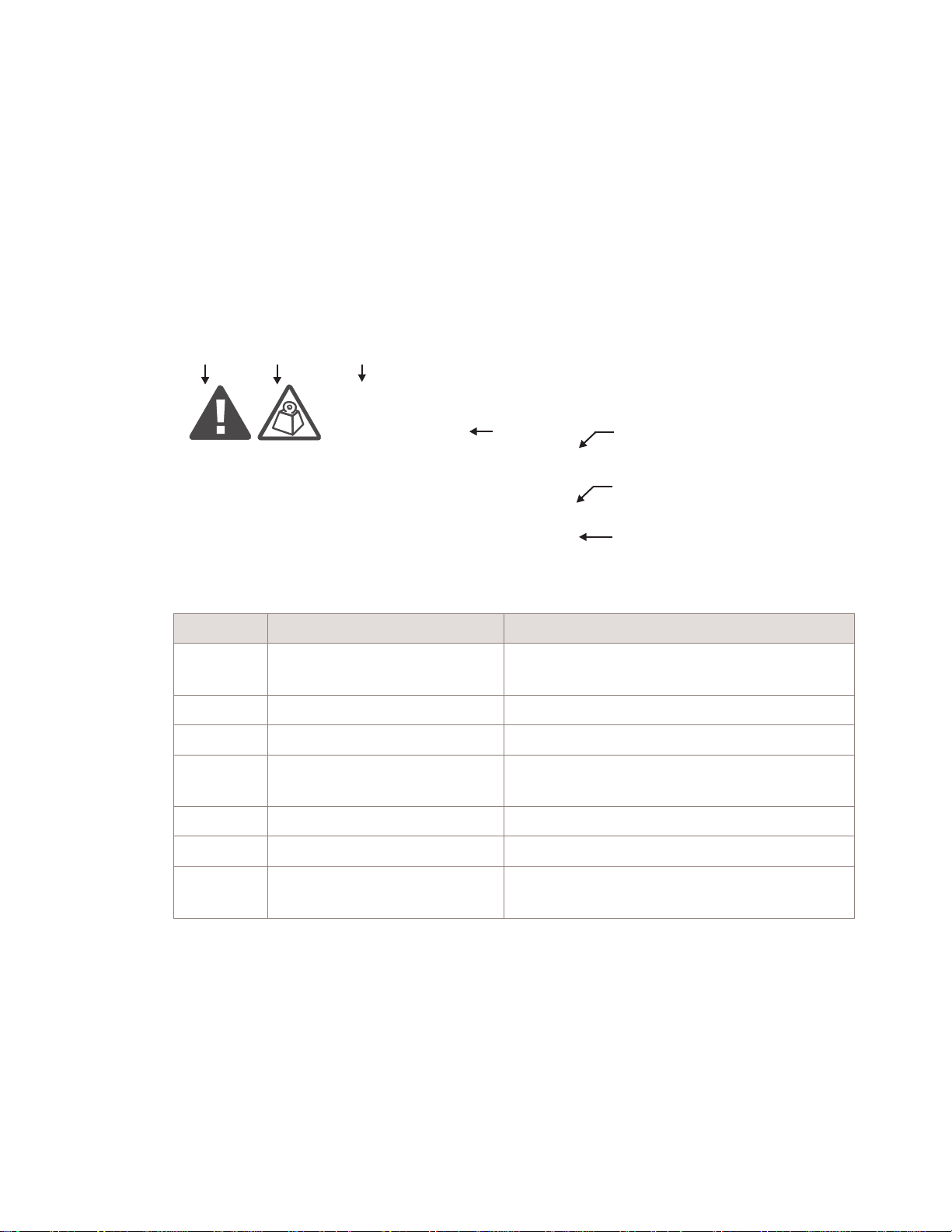
Safety statements include the following structural elements:
BC D
CAUTION
Lifting hazard
Lifting this equipment by yourself can result in injury
due to the size and weight of the equipment.
Always use three people or a lifting device to transport
and position this equipment. [ABC123]
SAMPLE
Item Structure element Purpose
1 Safety alert symbol Indicates the potential for personal injury
2 Safety symbol Indicates hazard type (optional)
3 Signal word Indicates the severity of the hazard
4 Hazard type Describes the source of the risk of damage or
5 Safety message Consequences if protective measures fail
6 Avoidance message Protective measures to take to avoid the hazard
7 Identifier The reference ID of the safety statement
E
(optional)
injury
(optional)
F
G
H
....................................................................................................................................................................................................................................
1-2
Alcatel-Lucent – Proprietary
Use pursuant to applicable agreements
Alcatel-Lucent 9763 MCI
3MN-MCI-IMOP
Issue 1 December 2013
Page 18

Safety statements Structure of safety statements
....................................................................................................................................................................................................................................
Signal words
The signal words identify the hazard severity levels as follows:
Signal word Meaning
DANGER Indicates an extremely hazardous situation which, if not avoided, will
result in death or serious injury.
WARNING Indicates a hazardous situation which, if not avoided, could result in
death or serious injury.
CAUTION Indicates a hazardous situation which, if not avoided, could result in
minor or moderate injury.
NOTICE Indicates a hazardous situation not related to personal injury.
....................................................................................................................................................................................................................................
Alcatel-Lucent 9763 MCI
3MN-MCI-IMOP
Issue 1 December 2013
Alcatel-Lucent – Proprietary
Use pursuant to applicable agreements
1-3
Page 19

Safety statements Safety
....................................................................................................................................................................................................................................
Safety
General precautions for installation procedures
WARNING
Failure to observe these safety precautions may result in personal
injury or damage to equipment.
• Read and understand all instructions.
• Follow all warnings and instructions marked on this product.
• Installation and maintenance procedures must be followed and performed by
trained personnel only.
• The equipment must be provided with a readily accessible disconnect device
as part of site preparation.
• Grounding and circuit continuity is vital for safe operation of the equipment.
Never operate the equipment with grounding/bonding conductor
disconnected.
• Install only equipment identified in the product's installation manual. Use of
other equipment may result in an improper connection which could lead to
fire or injury.
• Use caution when installing or modifying telecommunications equipment.
• Before servicing, disconnect power input to reduce the risk of energy
hazards.
• For continued protection against risk of fire, all fuses used in this product
must be replaced only with fuses of the same type and rating.
• Never install telecommunications equipment during a lightning storm or
when conditions are wet.
• Never touch uninsulated wiring or terminals carrying direct current or
ringing current, and never leave this wiring exposed. Protect and tape
uninsulated wiring and terminals to avoid risk of fire, electrical shock, and
injury to personnel.
• Never spill liquids of any kind on the product.
• To reduce the risk of an electrical shock, do not disassemble the product.
Opening and removing covers and/or circuit boards may expose you to
dangerous voltages or other risks. Incorrect reassembly can cause electrical
shock when the unit is subsequently used.
• for PERMANENTLY CONNECTED EQUIPMENT, a readily accessible
disconnect device must be incorporated external to the equipment.
....................................................................................................................................................................................................................................
1-4
Alcatel-Lucent – Proprietary
Use pursuant to applicable agreements
Alcatel-Lucent 9763 MCI
3MN-MCI-IMOP
Issue 1 December 2013
Page 20
Safety statements Safety - specific hazards
....................................................................................................................................................................................................................................
Safety - specific hazards
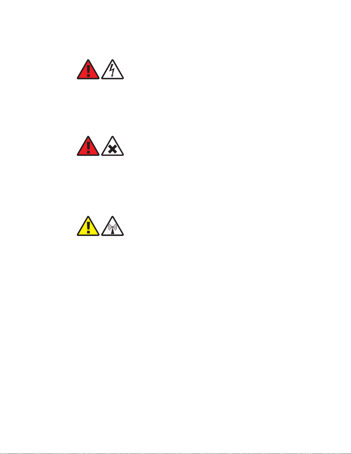
DANGER
Electric-shock hazard
Working in severe weather can result in personal injury or death and damage to the
equipment.
Never install or perform maintenance during severe weather (high winds, lightning,
blizzards, hurricane etc.).
DANGER
Noxious-substance hazard
Use of unspecified cleaning agents can result in personal injury.
Use only specified cleaning agents. Never use flammable solvents.
Always ensure there is adequate ventilation in the work area and wear the appropriate
personal protective equipment.
CAUTION
RF hazard
RF exposure in excess of applicable limits can result in personal injury.
Metro Cells are designed and installed in order that they are compliant with the
international exposure guidelines laid down by the International Commission on
Non-Ionizing Radiation Protection (ICNIRP).
For all staff that are required to work in close proximity to the equipment, for example
maintenance personnel, contact with the antenna should be avoided. No such persons
shall stay in front of the product at a distance of less than 8 cm.
No other persons shall stay in front of the product at a distance of less than 22 cm.
....................................................................................................................................................................................................................................
Alcatel-Lucent 9763 MCI
3MN-MCI-IMOP
Issue 1 December 2013
Alcatel-Lucent – Proprietary
Use pursuant to applicable agreements
1-5
Page 21
Safety statements Safety - specific hazards
....................................................................................................................................................................................................................................
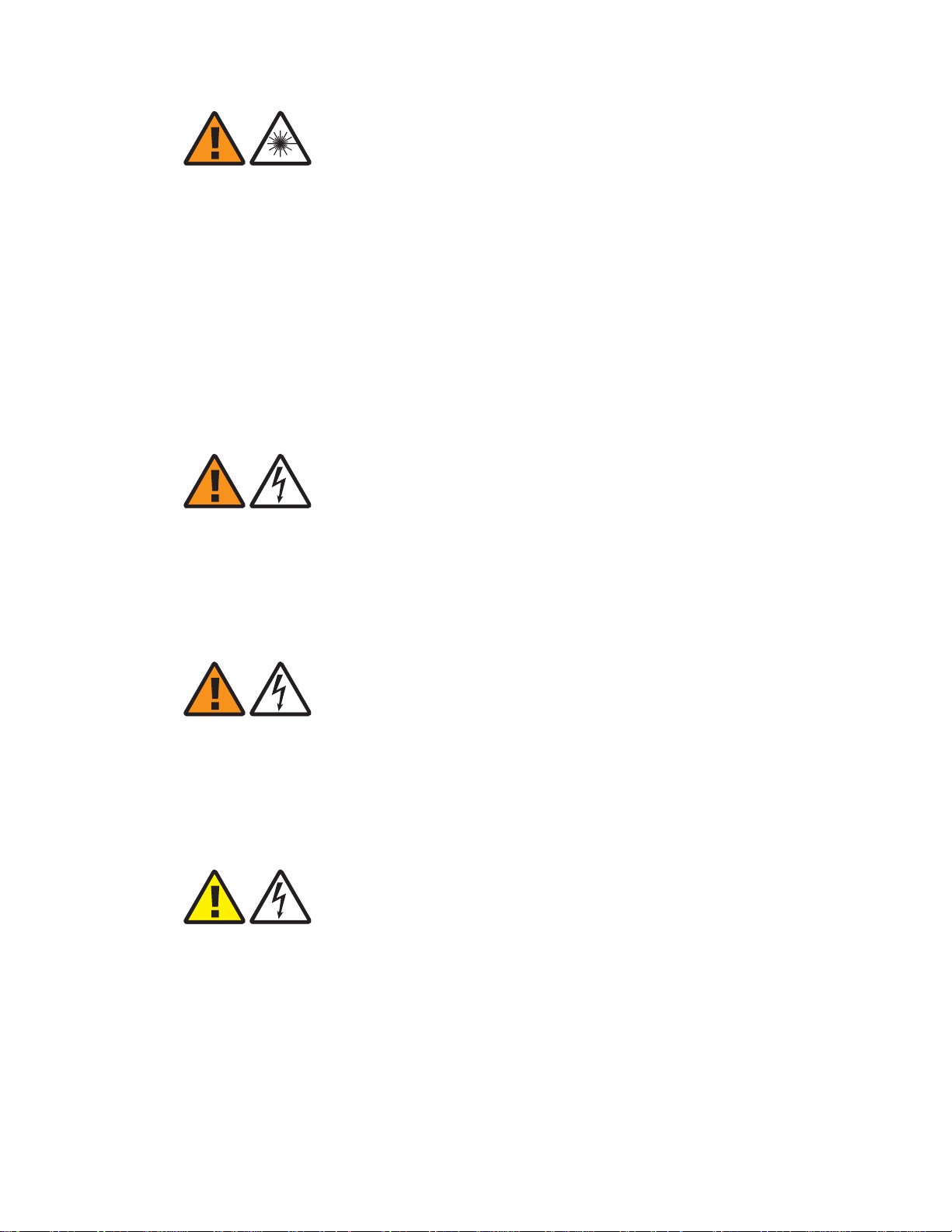
WARNING
Laser hazard
Use of controls or adjustments or performance of procedures other than those specified
herein may result in hazardous laser radiation exposure.
Do not view directly into the laser beam with optical instruments such as a fiber
microscope because viewing of laser emission in excess of Class 1 limits significantly
increases the risk of eye damage.
Never look into the end of an exposed fiber or an open connector as long as the optical
source is switched on.
Ensure that the optical source is switched off before disconnecting optical fiber
connectors.
WARNING
Electric-shock hazard
Some parts of all electrical installations are energized. Failure to observe this fact and
the safety warnings may lead to bodily injury and property damage.
For this reason, only trained and qualified personnel (electrical workers as defined in
IEC 60215 + A1 or EN 60215) may install or service the installation.
WARNING
Electric-shock hazard
The power supply lines to the equipment are energized. Contact with parts carrying
current can cause serious injury, possibly including death, even hours after the event.
Turn off and lock out the system power at the disconnect device before working on or
servicing the equipment.
CAUTION
Electric-shock hazard
DOUBLE POLE/NEUTRAL FUSING
A fuse is used in the neutral of single-phase equipment either permanently connected or
provided with a non-reversible plug. After operation of the fuse, parts of the equipment
that remain energized might represent a hazard during servicing.
Failure to observe this fact and the safety warnings may lead to bodily injury and
property damage.
....................................................................................................................................................................................................................................
1-6
Alcatel-Lucent – Proprietary
Use pursuant to applicable agreements
Alcatel-Lucent 9763 MCI
3MN-MCI-IMOP
Issue 1 December 2013
Page 22
Safety statements Safety - specific hazards
....................................................................................................................................................................................................................................
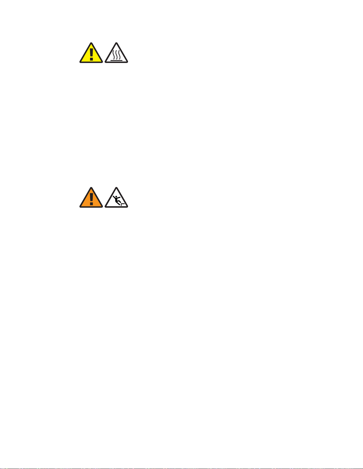
CAUTION
Hot-surface hazard
The surfaces of the MCI can become hot enough to cause burns on unprotected skin.
Before handling the unit, wait until its surfaces have cooled and, where the following
conditions apply, ensure that it is mounted out of the public's reach.
For installations in ambient temperatures exceeding 25° C, the surface temperature of the
aluminium housing may be considerably higher:
• 52°C at an ambient temperature of 25°C
• 64°C at an ambient temperature of 35°C
• 81°C at an ambient temperature of 50°C
In these situations, this equipment is intended for installation where access is restricted to
only qualified service personnel.
WARNING
Fall hazard
Falls can occur when working at heights resulting in serious personal injury or death.
To prevent a fall when working at heights (ladder, scaffold, manlift, roof etc.) follow safe
work practices and wear appropriate fall protection equipment.
....................................................................................................................................................................................................................................
Alcatel-Lucent 9763 MCI
3MN-MCI-IMOP
Issue 1 December 2013
Alcatel-Lucent – Proprietary
Use pursuant to applicable agreements
1-7
Page 23

Safety statements Safety - specific hazards
....................................................................................................................................................................................................................................
NOTICE
ESD hazard
Semiconductor devices can be damaged by electrostatic discharges (ESD)
The following rules must be complied with when handling any module containing
semiconductor components:
• Wear conductive or antistatic working clothes (for example, coat made of 100%
cotton).
• Wear a grounded wrist strap.
• Wear shoes with conductive soles on a conductive floor surface or conductive work
mat.
• Leave the modules in their original packaging until ready for use.
• Make sure there is no difference in potential between yourself, the workplace, and the
packaging before removing, unpacking, or packing a module.
• Whenever handling ESD-sensitive components, do not touch any connection pins or
tracks.
• Place modules removed from the equipment on a conductive surface.
• Test or handle the module only with grounded tools on grounded equipment.
• Handle defective modules exactly like new ones to avoid causing further damage.
NOTICE
Condensation
Sudden changes in the weather may lead to the formation of condensation on
components. Operating the unit when condensation moisture is present can destroy the
unit.
Units which show signs of condensation must be dried before installation.
NOTICE
Tools
Tools left in the working area can cause short circuits during operation which can lead to
the destruction of units.
Make sure after finishing your work that no tools, testing equipment, flashlights, etc.,
have been left in or on the equipment.
....................................................................................................................................................................................................................................
1-8
Alcatel-Lucent – Proprietary
Use pursuant to applicable agreements
Alcatel-Lucent 9763 MCI
3MN-MCI-IMOP
Issue 1 December 2013
Page 24

Safety statements Product safety
....................................................................................................................................................................................................................................
Product safety
Equipment safety
Safety information for this equipment can be found on various Caution, Warning, Danger,
information labels or instructions affixed to or included with the product or included
within this document. Informational and cautionary labels may appear near the item they
address or may be grouped in a single location on the equipment. Warnings are typically
adjacent to the hazard that is noted on the label. The instructions, cautions and warnings
found on these labels must be understood and observed by all personnel involved with the
equipment installation and maintenance.
....................................................................................................................................................................................................................................
Alcatel-Lucent 9763 MCI
3MN-MCI-IMOP
Issue 1 December 2013
Alcatel-Lucent – Proprietary
Use pursuant to applicable agreements
1-9
Page 25

Safety statements Product safety
....................................................................................................................................................................................................................................
....................................................................................................................................................................................................................................
1-10
Alcatel-Lucent – Proprietary
Use pursuant to applicable agreements
Alcatel-Lucent 9763 MCI
3MN-MCI-IMOP
Issue 1 December 2013
Page 26

2 2Hardware architecture
and functionality
Overview
Purpose
This chapter provides an overview of the hardware architecture and product functionality
of the Alcatel-Lucent 9763 Metro Cell Indoor.
Contents
Functional description 2-2
Physical description 2-3
Supported installation options 2-8
Hardware and ancillary items 2-10
...................................................................................................................................................................................................................................
Alcatel-Lucent 9763 MCI
3MN-MCI-IMOP
Issue 1 December 2013
Alcatel-Lucent – Proprietary
Use pursuant to applicable agreements
2-1
Page 27

Hardware architecture and functionality Functional description
....................................................................................................................................................................................................................................
Functional description
General description
Alcatel-Lucent Metro Cells product family enables mobile service providers (MSPs) to
deliver cost-effective capacity to high-density areas. They also enhance the quality of
experience (QoE) for end users by enabling faster, more reliable data connections and
higher data throughput on 4G networks. The product can be deployed by mobile operators
to provide a transparent outdoor capacity layer to complement the macro cell “umbrella”
coverage layer.
The Alcatel-Lucent 9763 Metro Cell Indoor product specified here is targeted for indoor,
high user density locations where additional capacity is required within a small footprint,
such as businesses and shopping malls.
Product features and capabilities
The product features and capabilities in this release are as follows:
• Supports LTE FDD.
• Single LTE carrier.
• PCS (1900 MHz - B25) frequency band.
• Supports up to 64 users simultaneously.
• High transmit power: 250mW at each antenna connector, and an Equivalent
Isotropically Radiated Power (EIRP) of 28 dBm per path.
• Capable of supporting 30 Mbps downlink (1930 to 1995 MHz) and a 9 Mbps uplink
(1850 to 1915 MHz) in the 5 MHz bandwidth.
• Supports two internal, quasi-omnidirectional, spatially-separated antennas (4 dBi
gain).
Supports cabling to optional external antennas (used instead of the integrated
antennas).
• Standard 2x2 MIMO configurations, 2 transmit and 2 receive diversity.
• Receiver sensitivity for LTE channel bandwidths 5 MHz optimized to permit near far
simultaneous operation, with Rx sensitivity at -98 dBm.
• Supports Gigabit Ethernet backhaul and daisy chaining to one additional 9763 MCI.
Attention: The 9763 MCI product has feature parity with some but not all macro
eNodeB features. See the Alcatel-Lucent LTE RAN eNodeB Macro and Metro
Products - LR13.3.L - FDD Release Notes, 9YZ-05817-0001-FMZZA.
....................................................................................................................................................................................................................................
2-2
Alcatel-Lucent – Proprietary
Use pursuant to applicable agreements
Alcatel-Lucent 9763 MCI
3MN-MCI-IMOP
Issue 1 December 2013
Page 28

Hardware architecture and functionality Physical description
....................................................................................................................................................................................................................................
Physical description
Product overview
The Alcatel-Lucent 9763 Metro Cell Indoor is designed for indoor installations and is
housed in an Alcatel-Lucent passively-cooled enclosure containing the following active
components/modules:
Module Functions
Power AC/DC power conversion
MEMO board Digital processing
Backhaul board Backhaul interface
Radio Radio, PA, Filter, Antennas
The 9763 MCI external views are reflected in the following figure.
Figure 2-1 9763 MCI hardware- front and back views
Front view
Weights and dimensions
The physical dimensions of the 9763 MCI are:
Dimensions (Length x Width x
Depth)
Back view
287 x 227 x107 (mm)
Volume 6.9 L
Weight 4.8 kg
....................................................................................................................................................................................................................................
Alcatel-Lucent 9763 MCI
3MN-MCI-IMOP
Issue 1 December 2013
Alcatel-Lucent – Proprietary
Use pursuant to applicable agreements
2-3
Page 29

Hardware architecture and functionality Physical description
....................................................................................................................................................................................................................................
Connection interfaces
The following figure shows the connection interfaces for the 9763 MCI.
Figure 2-2 9763 MCI connection interfaces
Power supply
Connection location Description
9763 MCI (back) External GPS antenna connector (for external GPS antenna)
RF antenna connectors (two)
SFP connectors (two) - one for backhaul and one for
daisychaining
AC power supply connector
The 9763 MCI requires an uninterruptible AC power feed (single phase, three-wire
voltage source).
• Input voltage range: 85Vac - 270Vac
• Nominal voltages: 110Vac and 230Vac
• Frequency: 47Hz - 63Hz
A power module unit inside the 9763 MCI:
• Supports 90W power consumption.
• Provides AC/DC conversion (5.3V output) and distributes 5.3V to PCBs within the
unit.
....................................................................................................................................................................................................................................
2-4
Alcatel-Lucent – Proprietary
Use pursuant to applicable agreements
Alcatel-Lucent 9763 MCI
3MN-MCI-IMOP
Issue 1 December 2013
Page 30

Hardware architecture and functionality Physical description
....................................................................................................................................................................................................................................
The AC input port satisfies the first and second level surge protection requirements
specified for port type 7 in GR-1089, Issue 6. Voltage spikes with a duration of ≤10µs are
ignored.
The internal power module is designed such that when an “under voltage”, “over
voltage”, or “over temperature” condition occurs, the power module automatically shuts
off, then automatically restarts when the conditions are within the acceptable limits.
Backhaul
The 9763 MCI supports two SFP interfaces for backhaul. as follows:
• 1000Base-X GigE optical transceiver
• 10/100/1000Base-T electrical transceiver
One SFP (BH1) may be cabled for backhaul to the network while the other SFP (BH2)
may be cabled for daisychaining to another 9763 MCI. Two 9763 MCIs may be
daisychained together.
RF Antennas
The 9763 MCI contains two internal quasi-omnidirectional, spatially-separated antennas
configured for 2x2 MIMO.
The vertical plane half-power beamwidth (HPBW) is typically 90° for each of the
antennas
The RF antenna connectors are located externally on the rear of the unit, providing the
service provider the option of connecting the internal RF antennas or connecting two
externally cabled RF antennas.
GPS Antenna
The 9763 MCI has a connector for an external GPS antenna to provide frequency and
phase synchronization.
Status indicator
The 9763 MCI supports a single bi-color LED (red/green) which is located on the rear
lower portion of the 9763 MCI. The LED is not intended for use during normal operation
of the equipment, however, it can provide a visual status of the equipment during initial
installation and commissioning. Refer to the LED interpretation table in
“LED State Description”
Appendix A,
for details.
....................................................................................................................................................................................................................................
Alcatel-Lucent 9763 MCI
3MN-MCI-IMOP
Issue 1 December 2013
Alcatel-Lucent – Proprietary
Use pursuant to applicable agreements
2-5
Page 31

Hardware architecture and functionality Physical description
....................................................................................................................................................................................................................................
Figure 2-3 LED position and orientation
Product labelling
The 9763 MCI module has the following labelling:
1. A product label reflecting:
2. A regulatory label reflecting:
LED
• Vendor name/Icon
• Model name
• Part number
• Serial number
• Data matrix barcode for Part number and Serial number
• Vendor name/Icon
• Product name
• Regulatory rules
• Power input
• Enclosure rating
• Applicable regulatory and environmental certification logos
• Manufacturer name
....................................................................................................................................................................................................................................
2-6
Alcatel-Lucent – Proprietary
Use pursuant to applicable agreements
Alcatel-Lucent 9763 MCI
3MN-MCI-IMOP
Issue 1 December 2013
Page 32

Hardware architecture and functionality Physical description
....................................................................................................................................................................................................................................
3. An FCC label reflecting:
• Vendor name/Icon
• FCC ID
Product base items and configuration
The 9763 MCI product is delivered with the following base items:
• Alcatel-Lucent 9763 Metro Cell Indoor
Ancillary orderable items
In addition to the 9763 MCI base items, the following ancillary and variable items can be
ordered depending on the product configuration and deployment scenario:
• Mounting frame for wall installation
• AC power cable, 4.5 m (15 ft)
• SFP modules:
– GBE 1000BaseSX (optical)
– GBE 10/100/1000BaseT (electrical)
• Backhaul cables:
– Multimode Dual Fiber LC-LC, various lengths (optical)
– Ethernet cable, various lengths (electrical)
• External GPS antenna, installation kit and jumper cable
....................................................................................................................................................................................................................................
Alcatel-Lucent 9763 MCI
3MN-MCI-IMOP
Issue 1 December 2013
Alcatel-Lucent – Proprietary
Use pursuant to applicable agreements
2-7
Page 33

Hardware architecture and functionality Supported installation options
....................................................................................................................................................................................................................................
Supported installation options
Overview
The following section describes the supported installation options for the Alcatel-Lucent
9763 Metro Cell Indoor V1.0 B25 LTE 2x250mW product. These include:
• Standard wall mount installation.
• Standard wall mount installation with daisy chaining where two 9763 MCI modules
are daisy chained together and share the same backhaul port.
Standard installation options
The 9763 MCI can be installed in any indoor place such as business environments or
indoor public places (shopping malls, airports. etc.) and is designed to address mobile
service providers' (MSPs) need to place coverage and capacity where it's needed fast
(such as indoor high-use hotspots).
Figure 2-4 Wall mount Installation example
Front view
(9763 MCI locked to
mounting frame)
Back view
(9763 MCI unlocked
from mounting frame)
Daisy chain installation options
In a daisy chain installation configuration two 9763 MCIs can be daisy chained together,
where they share the same backhaul port, thus reducing the investment cost needed to
connect the 9763 MCIs to the backhaul network and aggregating the uplink traffic. Daisy
chain connectivity scenarios support 9763 MCIs that are co-located or 9763 MCIs that are
separated by some distance.
....................................................................................................................................................................................................................................
2-8
Alcatel-Lucent – Proprietary
Use pursuant to applicable agreements
Alcatel-Lucent 9763 MCI
3MN-MCI-IMOP
Issue 1 December 2013
Page 34

Hardware architecture and functionality Supported installation options
....................................................................................................................................................................................................................................
Figure 2-5 9763 MCI daisy chain installation example
9763 MCI 2x250mW
BH1
BH2
Electrical SFP
Backhaul
system
or
Optical SFP
Electrical cable or
Optical cable to
Backhaul system
9763 MCI 2x250mW
BH1
BH2
Electrical SFP
or
Optical SFP
Electrical or Optical
daisy chain cable
Note: Daisy chain installation configurations will be available at LR13.3.L GA. The
backhaul chain will be limited to two MCI in this initial release.
....................................................................................................................................................................................................................................
Alcatel-Lucent 9763 MCI
3MN-MCI-IMOP
Issue 1 December 2013
Alcatel-Lucent – Proprietary
Use pursuant to applicable agreements
2-9
Page 35

Hardware architecture and functionality Hardware and ancillary items
....................................................................................................................................................................................................................................
Hardware and ancillary items
Overview
The following section lists the Alcatel-Lucent 9763 Metro Cell Indoor V1.0 B25 LTE
2x250mW base hardware equipment, the installation kits and ancillary items that can be
ordered from Alcatel-Lucent.
9763 MCI base items
The 9763 MCI packaging contains the following base items:
• Alcatel-Lucent 9763 Metro Cell Indoor V1.0 B25 LTE 2x250mW module
Mounting bracket
The following table list the mounting bracket that is available for order from
Alcatel-Lucent in support of the equipment installation options.
Item Description Use
Ancillary items
Mounting bracket Bracket for mounting 9763 MCI onto
a wall or ceiling
Mandatory
All installation scenarios (wall/ceiling)
The following tables list the ancillary items that are available for order from
Alcatel-Lucent in support of the defined equipment installation and configuration options.
Power
Item Description Use
Power cable AC patch power cord compatible
with a Standard IEC60320 C16
socket
SFP modules
Item Description Use
SFP module 10/100/1000Base-T electrical
transceiver
SFP module 1000Base-SX GigE optical
transceiver
Mandatory
Optional
Used if backhaul interface is optical
Optional
Used if backhaul interface is electrical
....................................................................................................................................................................................................................................
2-10
Alcatel-Lucent – Proprietary
Use pursuant to applicable agreements
Alcatel-Lucent 9763 MCI
3MN-MCI-IMOP
Issue 1 December 2013
Page 36

Hardware architecture and functionality Hardware and ancillary items
....................................................................................................................................................................................................................................
Ethernet cable - Electrical
Item Description Use
Electrical Ethernet cable 2m outdoor, 4 pairs, 2 RJ45 Optional
Use with 10/100/1000Base-T electrical
transceiver
Electrical Ethernet cable 25m outdoor, 4 pairs, 2 RJ45 Optional
Use with 10/100/1000Base-T electrical
transceiver
Electrical Ethernet cable 100m outdoor, 4 pairs, 2 RJ45 Optional
Use with 10/100/1000Base-T electrical
transceiver
Ethernet cable - Optical
Item Description Use
Fiber Optic cable 2.5m Multimode Dual Fiber LC-LC Optional
1000Base-SX GigE optical transceiver
Fiber Optic cable 5m Multimode Dual Fiber LC-LC Optional
1000Base-SX GigE optical transceiver
Fiber Optic cable 15m Multimode Dual Fiber LC-LC Optional
1000Base-SX GigE optical transceiver
Fiber Optic cable 30m Multimode Dual Fiber LC-LC Optional
1000Base-SX GigE optical transceiver
Fiber Optic cable 50m Multimode Dual Fiber LC-LC Optional
1000Base-SX GigE optical transceiver
Fiber Optic cable 70m Multimode Dual Fiber LC-LC Optional
1000Base-SX GigE optical transceiver
Fiber Optic cable 85m Multimode Dual Fiber LC-LC Optional
1000Base-SX GigE optical transceiver
Fiber Optic cable 100m Multimode Dual Fiber LC-LC Optional
1000Base-SX GigE optical transceiver
Fiber Optic cable 150m Multimode Dual Fiber LC-LC Optional
1000Base-SX GigE optical transceiver
Fiber Optic cable 200m Multimode Dual Fiber LC-LC Optional
1000Base-SX GigE optical transceiver
Fiber Optic cable 250m Multimode Dual Fiber LC-LC Optional
1000Base-SX GigE optical transceiver
Fiber Optic cable 300m Multimode Dual Fiber LC-LC Optional
1000Base-SX GigE optical transceiver
....................................................................................................................................................................................................................................
Alcatel-Lucent 9763 MCI
3MN-MCI-IMOP
Issue 1 December 2013
Alcatel-Lucent – Proprietary
Use pursuant to applicable agreements
2-11
Page 37

Hardware architecture and functionality Hardware and ancillary items
....................................................................................................................................................................................................................................
....................................................................................................................................................................................................................................
2-12
Alcatel-Lucent – Proprietary
Use pursuant to applicable agreements
Alcatel-Lucent 9763 MCI
3MN-MCI-IMOP
Issue 1 December 2013
Page 38

3 39763 MCI installation
Overview
Purpose
This chapter provides information and procedures for mounting the Alcatel-Lucent 9763
Metro Cell Indoor onto a wall.
Contents
9763 MCI pre-installation 3-2
9763 MCI Pre-installation information 3-3
9763 MCI installation clearances 3-5
9763 MCI daisy chain requirements 3-6
9763 MCI installation 3-9
Procedure 3-1: Mount the 9763 MCI onto a wall 3-10
...................................................................................................................................................................................................................................
Alcatel-Lucent 9763 MCI
3MN-MCI-IMOP
Issue 1 December 2013
Alcatel-Lucent – Proprietary
Use pursuant to applicable agreements
3-1
Page 39

9763 MCI installation
9763 MCI pre-installation
....................................................................................................................................................................................................................................
Overview
9763 MCI pre-installation
Overview
Purpose
This section provides pre-installation information (including required tools and materials
and installation clearances) as well as outlining the possible daisy chain deployment
scenarios and requirements for the Alcatel-Lucent 9763 Metro Cell Indoor product.
Contents
9763 MCI Pre-installation information 3-3
9763 MCI installation clearances 3-5
9763 MCI daisy chain requirements 3-6
....................................................................................................................................................................................................................................
3-2
Alcatel-Lucent – Proprietary
Use pursuant to applicable agreements
Alcatel-Lucent 9763 MCI
3MN-MCI-IMOP
Issue 1 December 2013
Page 40

9763 MCI installation
9763 MCI pre-installation
....................................................................................................................................................................................................................................
9763 MCI Pre-installation information
9763 MCI Pre-installation information
Verify site preparation
The following site preparation requirements should be checked and met before the
installation of the equipment can begin. If some of the requirements are not met, the
installer must do so now:
• Ensure equipment is planned to be installed as high as possible to avoid obstructions
• Consider nearby sources of interference. Also check possibility of future obstructions.
• Ensure adequate clearance is provided for service access
• Ground, power and backhaul cabling has been routed and is in place
• Ensure any site specific fixing materials (screws, washers, wall plugs) for pole/wall
mounting the equipment are available.
Product delivery contents
Unpack and examine the product packaging contents. If you notice any damage, or
missing items as listed in the Packing List, immediately notify the carrier that delivered
the unit and contact your Alcatel-Lucent representative.
The product packaging contains the following items:
• The Alcatel-Lucent 9763 Metro Cell Indoor V1.0 B25 LTE 2x250mW.
Installation materials
In addition to the standard product deliverable ensure the appropriate mounting brackets,
installation kits and ancillary items are available to support the product mounting options.
Figure 3-1 9763 MCI mounting bracket
....................................................................................................................................................................................................................................
Alcatel-Lucent 9763 MCI
3MN-MCI-IMOP
Issue 1 December 2013
Alcatel-Lucent – Proprietary
Use pursuant to applicable agreements
3-3
Page 41

9763 MCI installation
9763 MCI pre-installation
....................................................................................................................................................................................................................................
9763 MCI Pre-installation information
Table 3-1 Recommended wall anchor materials
Surface structure Recommended anchor materials Recommended screw torque
Wood Screw Hex T M8x70 stainless steel (x4)
Concrete Screw CHC M6x80 stainless steel (x4)
Tools required for installation
The following tools may be used during installation:
• Drill (pneumatic hammer) and assorted drill bits
• Pliers
• Adjustable spanners
• M17 socket wrench
• Screwdrivers (power and/or manual):
– Phillips (flat blade)
– Torx (T-25 and T-40)
• HRS (Hirose) HT206/TM21p-88p crimping tool (for RJ45 cable)
7.0 N.m (62.0 lb.in).
Washer plain M8x16x1.6 stainless steel (x4)
7.0 N.m (62.0 lb.in).
Washer plain M6x12x1.6mm stainless steel (x4)
Washer spring M6x12x1.2mm stainless steel (x4)
Plug expansion Rawlnut M6x50 (x4)
• Data cable tester for shielded RJ45 (optional)
• Measuring tape
• Digital compass (to aid establishing product orientation)
• Marker, to mark wall mounting holes
• Vacuum cleaner or equivalent (required for clearing debris from wall mounting holes)
• Spirit level
• Hammer
• PIB (self-amalgamating) tape and 3M Super 33+ vinyl tape
• Ear protectors and safety goggles/glasses
• Assorted cable ties (various lengths)
• Heavy duty tape
• Adjustable straps
....................................................................................................................................................................................................................................
3-4
Alcatel-Lucent – Proprietary
Use pursuant to applicable agreements
Alcatel-Lucent 9763 MCI
3MN-MCI-IMOP
Issue 1 December 2013
Page 42

9763 MCI installation
9763 MCI pre-installation
....................................................................................................................................................................................................................................
9763 MCI installation clearances
9763 MCI installation clearances
Minimum installation clearances
The following provides the minimum wall mount clearances recommended around the
Alcatel-Lucent 9763 Metro Cell Indoor V1.0 B25 LTE 2x250mW.
Figure 3-2 9763 Metro Cell Indoor installation clearances
Front view
(9763 MCI locked to
mounting frame)
9763 MCI Minimum clearances
Comment
Back view
(9763 MCI unlocked
from mounting frame)
mm (inches)
Side 250 mm (10 inches) To swing the 9763 MCI away from the
mounting frame to gain access to the back of
the unit.
Top 400 mm (16 inches) For free air flow and cable routing.
Bottom 400 mm (16 inches) For free air flow and cable routing.
Front 250 mm (10 inches) To swing the 9763 MCI away from the
mounting frame to gain access to the back of
the unit and the connection interfaces.
Rear Not applicable Rear clearance is defined by the supplied
mounting frame.
....................................................................................................................................................................................................................................
Alcatel-Lucent 9763 MCI
3MN-MCI-IMOP
Issue 1 December 2013
Alcatel-Lucent – Proprietary
Use pursuant to applicable agreements
3-5
Page 43

9763 MCI installation
9763 MCI pre-installation
....................................................................................................................................................................................................................................
9763 MCI daisy chain requirements
9763 MCI daisy chain requirements
Overview
Two 9763 MCI can be daisy chained together to share the same backhaul port, reducing
the investment cost needed to connect individual 9763 MCI to the backhaul network and
aggregating the uplink traffic. The daisy chain link between two 9763 MCI can be the
same as the backhaul link (either electrical or optical) or a mixed link configuration is
possible as shown in the following deployment scenario's.
Note: Physically the backhaul SFP port BH1 is on top of daisy chain SFP port BH2.
BH1SFP port
BH2 SFP port
(back)
(front)
Electrical link for backhaul and daisy chain
The following shows the deployment scenario for electrical backhaul and daisy chaining.
For daisy chaining to another 9763 MCI and additional cable and SFP are required.
Figure 3-3 Electrical backhaul and daisy chain configuration
9763 MCI 2x250mW
10/100/1000Base-T
SFP
BH1
Backhaul
system
Electrical cable to
Backhaul system
BH2
10/100/1000Base-T
SFP
Electrical
daisy chain cable
9763 MCI 2x250mW
BH1
BH2
....................................................................................................................................................................................................................................
3-6
Alcatel-Lucent – Proprietary
Use pursuant to applicable agreements
Alcatel-Lucent 9763 MCI
3MN-MCI-IMOP
Issue 1 December 2013
Page 44

9763 MCI installation
9763 MCI daisy chain requirements
9763 MCI pre-installation
....................................................................................................................................................................................................................................
Optical link for backhaul and daisy chain
The following shows the deployment scenario for optical backhaul and daisy chaining.
For daisy chaining to another 9763 MCI and additional cable and SFP are required.
Figure 3-4 Optical backhaul and daisy chain configuration
1000Base-SX SFP
(850nm wavelength)
Backhaul
system
Optical (multimode dual fiber)
cable to backhaul system
Mixed link for backhaul and daisy chain
The following shows the deployment scenario's for mixed optical/electrical backhaul and
daisy chaining. For daisy chaining to another 9763 MCI and additional cable and SFP are
required.
9763 MCI 2x250mW
BH1
BH2
1000Base-SX SFPs
(850nm wavelength)
Optical (multimode dual fiber)
daisy chain cable
9763 MCI 2x250mW
BH1
BH2
Figure 3-5 Mixed optical backhaul with electrical daisy chain configuration
9763 MCI 2x250mW
1000Base-SX SFP
(850nm wavelength)
10/100/1000Base-T
BH1
BH2
Backhaul
system
Optical (multimode dual fiber)
cable to backhaul system
....................................................................................................................................................................................................................................
Alcatel-Lucent 9763 MCI
3MN-MCI-IMOP
Issue 1 December 2013
Alcatel-Lucent – Proprietary
Use pursuant to applicable agreements
SFP
Electrical
daisy chain cable
9763 MCI 2x250mW
BH1
BH2
3-7
Page 45

9763 MCI installation
9763 MCI daisy chain requirements
9763 MCI pre-installation
....................................................................................................................................................................................................................................
Figure 3-6 Mixed electrical backhaul with optical daisy chain configuration
10/100/1000Base-T
SFP
Backhaul
system
9763 MCI 2x250mW
BH1
Electrical cable to
Backhaul system
BH2
1000Base-SX SFPs
(850nm wavelength)
Optical (multimode dual fiber)
daisy chain cable
9763 MCI 2x250mW
BH1
BH2
....................................................................................................................................................................................................................................
3-8
Alcatel-Lucent – Proprietary
Use pursuant to applicable agreements
Alcatel-Lucent 9763 MCI
3MN-MCI-IMOP
Issue 1 December 2013
Page 46

9763 MCI installation
9763 MCI installation
....................................................................................................................................................................................................................................
Overview
9763 MCI installation
Overview
Purpose
This section provides the installation instructions for mounting the Alcatel-Lucent 9763
Metro Cell Indoor onto a wall.
Contents
Procedure 3-1: Mount the 9763 MCI onto a wall 3-10
....................................................................................................................................................................................................................................
Alcatel-Lucent 9763 MCI
3MN-MCI-IMOP
Issue 1 December 2013
Alcatel-Lucent – Proprietary
Use pursuant to applicable agreements
3-9
Page 47

9763 MCI installation
9763 MCI installation
....................................................................................................................................................................................................................................
Procedure 3-1: Mount the 9763 MCI onto a wall
Procedure 3-1: Mount the 9763 MCI onto a wall
Purpose
This topic describes the procedures to be followed when installing the Alcatel-Lucent
9763 Metro Cell Indoor onto a wall or solid flat surface.
Prerequisites
A site survey has been conducted and a location for the device has been selected that is
both central to the public space and elevated in order to maximize coverage. Before
installation begins you should ensure the following are in place:
• Ensure adequate clearance is provided. See
(p. 3-5)
• Power cable has been routed and is in place
• Backhaul cable has been routed and is in place
• If required, daisy chain cable has been routed and is in place
• Any site specific fixing materials are available (for example, bolts, washers and wall
plug materials).
Attention: The 9763 MCI must be mounted with the appropriate mounting hardware
suitable for the various supporting structures, building materials and construction
methods. Following a site survey, it is the responsibility of the customer to ensure
that:
• the installation support structure is adequate and compliant with ICC IBC (2012):
International Building Code, and all other national and local codes
• the appropriate mounting hardware and any necessary recommended supporting
anchor fixings are used.
Wall mount installation
The 9763 MCI weighs 4.8 kg (10.6 lbs) and can be easily mounted onto solid concrete or
wooden flat surface using the following installation kits, anchor materials and tools.
“9763 MCI installation clearances”
• For installation and recommended anchor materials, see
“Installation materials”
(p. 3-3)
• For a list of installation tools, see “Tools required for installation” (p. 3-4)
Before you begin
Before you begin the following should be noted:
• Record the product 9763 MCI 18 digit serial number
• Equipment cabling should only be carried out by suitably trained or qualified
personnel and must comply with local and national electrical codes.
....................................................................................................................................................................................................................................
3-10
Alcatel-Lucent – Proprietary
Use pursuant to applicable agreements
Alcatel-Lucent 9763 MCI
3MN-MCI-IMOP
Issue 1 December 2013
Page 48

9763 MCI installation
9763 MCI installation
....................................................................................................................................................................................................................................
Procedure 3-1: Mount the 9763 MCI onto a wall
• As a prerequisite, backhaul cable has been routed from the backhaul system to the
9763 MCI.
• SFP port “BH1” may be cabled for backhaul to the network while the other SFP port
“BH2” may be cabled for daisy chaining to another 9763 MCI.
Perform standard wall mount installation
WARNING
Fall hazard
Falls can occur when working at heights resulting in serious personal injury or death.
To prevent a fall when working at heights (ladder, scaffold, manlift, roof etc.) follow safe
work practices and wear appropriate fall protection equipment.
Perform the following procedure to mount the 9763 MCI directly onto a wall.
...................................................................................................................................................................................................
Mount the 9763 MCI wall bracket (mounting frame) to the wall.
1
...................................................................................................................................................................................................
Attach 9763 MCI to the mounting bracket.
2
...................................................................................................................................................................................................
3
WARNING
Laser hazard
Use of controls or adjustments or performance of procedures other than those specified
herein may result in hazardous laser radiation exposure.
Do not view directly into the laser beam with optical instruments such as a fiber
microscope because viewing of laser emission in excess of Class 1 limits significantly
increases the risk of eye damage.
Never look into the end of an exposed fiber or an open connector as long as the optical
source is switched on.
Ensure that the optical source is switched off before disconnecting optical fiber
connectors.
....................................................................................................................................................................................................................................
Alcatel-Lucent 9763 MCI
3MN-MCI-IMOP
Issue 1 December 2013
Alcatel-Lucent – Proprietary
Use pursuant to applicable agreements
3-11
Page 49

9763 MCI installation
9763 MCI installation
....................................................................................................................................................................................................................................
Procedure 3-1: Mount the 9763 MCI onto a wall
NOTICE
ESD hazard
Semiconductor devices can be damaged by electrostatic discharges (ESD)
Always observe the general ESD instructions for handling modules containing
semiconductor components.
Install SFP module(s) into the SFP ports on the rear of the 9763 MCI.
...................................................................................................................................................................................................
Attach the Ethernet cable(s) to the SFP module(s) at the rear of the 9763 MCI.
4
...................................................................................................................................................................................................
Check attachment of RF antenna cables:
5
If you are using... Then...
the internal RF antennas antenna cables should already be attached to
the RF antenna connectors on the rear of the
9763 MCI.
external RF antennas detach the internal RF antenna 9763 MCI from
the connectors and attach the external RF
antenna cables.
...................................................................................................................................................................................................
6
WARNING
Electric-shock hazard
The current to the unit must be limited by an external fuse or circuit breaker incorporated
in the fixed wiring. The fuse or circuit breaker can be used as a disconnect device to turn
off the power to the system.
Ensure that the system power is off and that power cables are safe to handle before you
proceed with this procedure.
WARNING
Electric-shock hazard
The power supply lines to the equipment are energized. Contact with parts carrying
current can cause serious injury, possibly including death, even hours after the event.
Turn off and lock out the system power at the disconnect device before working on or
servicing the equipment.
....................................................................................................................................................................................................................................
3-12
Alcatel-Lucent – Proprietary
Use pursuant to applicable agreements
Alcatel-Lucent 9763 MCI
3MN-MCI-IMOP
Issue 1 December 2013
Page 50

9763 MCI installation
9763 MCI installation
....................................................................................................................................................................................................................................
Procedure 3-1: Mount the 9763 MCI onto a wall
Ensure that the power that feeds the AC power cable to the 9763 MCI is OFF. Block
access so that no one can restore power to that cable during this procedure.
Attention: Blocking access likely consists of not only putting a physical impediment
in the way, but also broadly circulating or broadcasting a warning about the hazard
and getting the cooperation of persons who have the authority to limit the access of
others.
Attach the power cable to the power connector on the rear of the 9763 MCI.
...................................................................................................................................................................................................
Swing the 9763 MCI toward the wall bracket (mounting frame) to hide access to the rear
7
of the unit, and lock the 9763 MCI in position using the key supplied with the 9763 MCI.
...................................................................................................................................................................................................
Ensure all cables are externally routed and secured.
8
E ND OF STEPS
...................................................................................................................................................................................................
....................................................................................................................................................................................................................................
Alcatel-Lucent 9763 MCI
3MN-MCI-IMOP
Issue 1 December 2013
Alcatel-Lucent – Proprietary
Use pursuant to applicable agreements
3-13
Page 51

9763 MCI installation Procedure 3-1: Mount the 9763 MCI onto a wall
....................................................................................................................................................................................................................................
....................................................................................................................................................................................................................................
3-14
Alcatel-Lucent – Proprietary
Use pursuant to applicable agreements
Alcatel-Lucent 9763 MCI
3MN-MCI-IMOP
Issue 1 December 2013
Page 52

Appendix A: LED State Description
Overview
Purpose
This chapter describes the LED status and descriptions for 9763 MCI.
Contents
LED status for 9763 MCI A-2
...................................................................................................................................................................................................................................
Alcatel-Lucent 9763 MCI
3MN-MCI-IMOP
Issue 1 December 2013
Alcatel-Lucent – Proprietary
Use pursuant to applicable agreements
A-1
Page 53

LED State Description LED status for 9763 MCI
....................................................................................................................................................................................................................................
LED status for 9763 MCI
Overview
This topic describes the LED status of the 9763 MCI device.
Figure A-1 LED position and orientation
LED
Hardware LED interpretation table
The following table describes the possible states for the single bi-color LED:
State Description LED
Power off Power off OFF
Initial state Power on or Restart ON (Red)
System Initializing, registering, and
performing auto-configuration
Failure Cell start-up or operational failure ON (Red)
Cell becomes operational Cell becoming operational ON (Green)
....................................................................................................................................................................................................................................
A-2
Software downloading Blinking (Green)
(Note: LED is switched OFF
after 15 minutes of stable
operation)
Alcatel-Lucent – Proprietary
Use pursuant to applicable agreements
Alcatel-Lucent 9763 MCI
Issue 1 December 2013
3MN-MCI-IMOP
Page 54

LED State Description LED status for 9763 MCI
....................................................................................................................................................................................................................................
State Description LED
Cell is operational Cell has been in stable operation for 15 minutes OFF
....................................................................................................................................................................................................................................
Alcatel-Lucent 9763 MCI
3MN-MCI-IMOP
Issue 1 December 2013
Alcatel-Lucent – Proprietary
Use pursuant to applicable agreements
A-3
Page 55

LED State Description LED status for 9763 MCI
....................................................................................................................................................................................................................................
....................................................................................................................................................................................................................................
A-4
Alcatel-Lucent – Proprietary
Use pursuant to applicable agreements
Alcatel-Lucent 9763 MCI
3MN-MCI-IMOP
Issue 1 December 2013
Page 56

Appendix B: Product conformance statements
Overview
Purpose
This section presents the product conformance statements that apply to the Alcatel-Lucent
9763 Metro Cell Indoor access point equipment.
The statements that are required are determined primarily by national or multi-national
regulations. However, in some regions, contract terms determine which statements are
required.
The presence of the statement indicates that the product does comply with that statement
wherever it is required to do so.
Contents
United States compliance B-2
Federal Communications Commission B-3
Product safety conformance statements B-4
Antenna exposure statements B-5
FDA/IEC optical transmitter product compliance statements B-6
Eco-environmental statements B-7
...................................................................................................................................................................................................................................
Alcatel-Lucent 9763 MCI
3MN-MCI-IMOP
Issue 1 December 2013
Alcatel-Lucent – Proprietary
Use pursuant to applicable agreements
B-1
Page 57

Product conformance statements
United States compliance
....................................................................................................................................................................................................................................
Introduction
United States compliance
Introduction
Purpose
The statements that follow are the product conformance statements that apply to the
Alcatel-Lucent 9763 Metro Cell Indoor when deployed in the United States.
Contents
Federal Communications Commission B-3
Product safety conformance statements B-4
Antenna exposure statements B-5
FDA/IEC optical transmitter product compliance statements B-6
Eco-environmental statements B-7
....................................................................................................................................................................................................................................
B-2
Alcatel-Lucent – Proprietary
Use pursuant to applicable agreements
Alcatel-Lucent 9763 MCI
3MN-MCI-IMOP
Issue 1 December 2013
Page 58

Product conformance statements
United States compliance
....................................................................................................................................................................................................................................
Federal Communications Commission
Federal Communications Commission
Federal Communications Commission
Important! Changes or modifications not expressly approved by Alcatel-Lucent, Inc.
could void the user’s authority to operate the equipment.
This device complies with Part 15 of the 47 CFR FCC Rules. Operation is subject to the
following two conditions:
(1) this device may not cause harmful interference, and
(2) this device must accept any interference received, including interference that may
cause undesired operation.
47 CFR FCC Part 15 Class B
Note: This equipment has been tested and found to comply with the limits for a Class
B digital device, pursuant to Part 15 of the 47 CFR FCC Rules.
These limits are designed to provide reasonable protection against harmful
interference in a residential installation.
RF approval
This equipment generates, uses, and can radiate radio frequency energy and, if not
installed and used in accordance with the instructions, may cause harmful interference
to radio communications. However, there is no guarantee that interference will not
occur in a particular installation.
If this equipment does cause harmful interference to radio or television reception,
which can be determined by turning the equipment off and on, the user is encouraged
to try to correct the interference by one or more of the following measures:
• Reorient or relocate the receiving antenna
• Increase the separation between the equipment and receiver
• Connect the equipment into an outlet on a circuit different from that to which the
receiver is connected
• Consult the dealer or an experienced radio/TV technician for help.
This equipment complies with Part 2, Subpart J - Equipment Authorization Procedures, of
the 47 CFR FCC Rules.
This equipment complies with Part 24 - Personal Communications Services, Subpart E Broadband PCS.
....................................................................................................................................................................................................................................
Alcatel-Lucent 9763 MCI
3MN-MCI-IMOP
Issue 1 December 2013
Alcatel-Lucent – Proprietary
Use pursuant to applicable agreements
B-3
Page 59

Product conformance statements
United States compliance
....................................................................................................................................................................................................................................
Product safety conformance statements
Product safety conformance statements
Product safety conformance
This equipment is Safety Certified for the United States of America by a Nationally
Recognized Test Laboratory (NRTL) accredited by the US Department of Labor,
Occupational Safety and Health Administration (OSHA), such as UL, CSA, or others.
The product bears this certification mark of this certification laboratory on its main
nameplate label. Should the local authority having jurisdiction (AHJ) require prior or
additional verification of this certification, a product certificate of compliance can be
obtained from the specific certification laboratory by the business/product unit Applicant
for the product or by contacting Alcatel-Lucent Technical Support. See the Alcatel-Lucent
Support web site ( (
Any modifications to this equipment are not permitted without review and official written
authorization from the specific Certification Body. Unauthorized changes may violate the
Product Safety Certification. Modifications or changes authorized by official CN/CNN
are assumed to have received prior approval from this Lab.
http://www.alcatel-lucent.com/support/)) for contact information.
Indoor applications
When external antennas are used, this equipment is intended for installation in restricted
access locations where access is controlled or where access can only be gained by service
personnel with a key or tool. Access to this equipment is restricted to qualified service
personnel only.
....................................................................................................................................................................................................................................
B-4
Alcatel-Lucent – Proprietary
Use pursuant to applicable agreements
Alcatel-Lucent 9763 MCI
3MN-MCI-IMOP
Issue 1 December 2013
Page 60

Product conformance statements
United States compliance
....................................................................................................................................................................................................................................
Antenna exposure statements
Antenna exposure statements
Antenna exposure
Equipment with integrated antennas
This equipment complies with FCC RF radiation exposure limits set forth in 47 CFR Part
1, Subpart I, Section 1.1310 for a general population/uncontrolled exposure environment.
The antenna(s) used for this transmitter shall be installed to provide a separation distance
of at least 20 cm from all persons when they are not co-located or operating in
conjunction with any other antenna or transmitter.
This equipment is equipped with two integrated quasi-omnidirectional antennas. Any
changes to the antenna or other equipment in the transmit path may require re-evaluation
of the exposures to electromagnetic fields.
Equipment with external antennas
Antenna installations for this equipment shall be performed in accordance with all
applicable manufacturer's recommendations, and national laws and regulations. To ensure
correct antenna installation, the antenna installer shall perform all necessary calculations
and/or field measurements to evaluate compliance with applicable national laws or
regulations regarding exposure to electromagnetic fields. The supplier of radio
equipment, the supplier of antenna equipment and the integrator and builder of the site
must provide sufficient information so that the limits of the exclusion zones can be
determined. Any changes to the antenna or other equipment in the transmit path may
require re-evaluation of the exposures to electromagnetic fields.
Pursuant to 47 CFR Part 1, Subpart I, subject to the provisions of section 1.1307, all
installations must be evaluated for requirements contained in Table 1, “Limits for
maximum permissible exposure”, in section 1.1310.
....................................................................................................................................................................................................................................
Alcatel-Lucent 9763 MCI
3MN-MCI-IMOP
Issue 1 December 2013
Alcatel-Lucent – Proprietary
Use pursuant to applicable agreements
B-5
Page 61

Product conformance statements
United States compliance
....................................................................................................................................................................................................................................
FDA/IEC optical transmitter product compliance statements
FDA/IEC optical transmitter product compliance statements
FDA/IEC optical transmitter product compliance
Alcatel-Lucent declares that this equipment complies with the Food and Drug
Administration’s Center for Devices and Radiological Health (FDA/CDRH) regulations
21 CFR 1040.10 and 1040.11. It is a Class I/1 laser optical fiber communication systems
“product” under the FDA.
This Product is designed to ensure that personnel operating the product are not
endangered by laser radiation during normal operation and fault conditions. This product
does not present a risk of eye injury because it is fully enclosed and does not contain
embedded lasers greater than Class I/1 unless otherwise noted.
....................................................................................................................................................................................................................................
B-6
Alcatel-Lucent – Proprietary
Use pursuant to applicable agreements
Alcatel-Lucent 9763 MCI
3MN-MCI-IMOP
Issue 1 December 2013
Page 62

Product conformance statements
United States compliance
....................................................................................................................................................................................................................................
Eco-environmental statements
Eco-environmental statements
Packaging collection and recovery requirements
Countries, states, localities, or other jurisdictions may require that systems be established
for the return and/or collection of packaging waste from the consumer, or other end user,
or from the waste stream. Additionally, reuse, recovery, and/or recycling targets for the
return and/or collection of the packaging waste may be established.
For more information regarding collection and recovery of packaging and packaging
waste within specific jurisdictions, contact the Alcatel-Lucent Environment, Health and
Safety organization or Alcatel-Lucent Hazardous Waste Center technical support at (888)
539-2783.
Material content compliance
The following notification applies to Alcatel-Lucent products distributed for sale, resale,
or use.
This product, part, or both may include a lithium-manganese dioxide battery, which
contains very small amounts of a perchlorate substance. Special handling may apply.
For California:
Perchlorate Material - special handling may apply.
See (
http://www.dtsc.ca.gov/hazardouswaste/perchlorate/).
....................................................................................................................................................................................................................................
Alcatel-Lucent 9763 MCI
3MN-MCI-IMOP
Issue 1 December 2013
Alcatel-Lucent – Proprietary
Use pursuant to applicable agreements
B-7
Page 63

Product conformance statements Eco-environmental statements
....................................................................................................................................................................................................................................
....................................................................................................................................................................................................................................
B-8
Alcatel-Lucent – Proprietary
Use pursuant to applicable agreements
Alcatel-Lucent 9763 MCI
3MN-MCI-IMOP
Issue 1 December 2013
Page 64

Glossary
...................................................................................................................................................................................................................................
Numerics
3GPP
3rd Generation Partnership Project
...................................................................................................................................................................................................................................
A A (Ampere)
Base SI unit of electrical current.
A-GPS
Assisted Global Positioning System
AC (Alternating Current)
Continuously variable current, rising to a maximum in one direction, falling to zero, then
reversing direction and repeating the cycle in the other direction.
AC convenience outlet
Sites must be equipped with at least two duplex outlets for installation and maintenance
procedures. The outlets are required to power test equipment and installation tools.
ACF (AC Fail)
The AC Fail (ACF) alarm indicates that AC input to one or more rectifiers in the power plant is
absent or outside of the operating range of the equipment
Ambient temperature
The temperature of air or other media in a designated area, particularly the area
ANSI (American National Standards Institute)
An organization chartered to accredit standards developed by a wide variety of industry groups,
without influence from any one company or organization. Does not develop standards, but
reviews and implements those developed by other organizations. ANSI is a member of the
International Standards Organization (ISO).
Antenna
An elevated device for radiating or receiving radio waves. It changes electrical currents into
electromagnetic waves, and vice versa.
AP (Application Processor)
Network element located at the MSC which provides the radio control logic for managing calls.
The AP is a general purpose computer that can host a number of RCS virtual machines.
....................................................................................................................................................................................................................................
Alcatel-Lucent 9763 MCI
3MN-MCI-IMOP
Issue 1 December 2013
Alcatel-Lucent – Proprietary
Use pursuant to applicable agreements
GL-1
Page 65

Glossary
....................................................................................................................................................................................................................................
AWG (American Wire Gauge)
American standard for classifying wire diameter.
...................................................................................................................................................................................................................................
B Backup
Facility used to replace an element which has failed.
Base station
The equipment that provides the air interface that allows mobile terminals to communicate with
the telecommunications network.
Bonding
Permanent connection of metallic parts to form an electrically conductive path that will assure
electrical continuity and have the capability to safely conduct any current likely to be imposed.
Branch circuit
The circuit conductors between the final overcurrent device protecting the circuit and the
outlet(s).
Breaker, circuit
A cut-out device which breaks a circuit when preset limits of current are exceeded.
Buried cable
A communication cable manufactured or produced for the purpose of burial in direct contact with
the earth.
Buried ring ground
A buried, bare, tinned, solid copper cable encircling the site building and/or tower foundation.
Bus bar
One or more conductors that serves as a common connection for a group of related devices.
Busy hour
The uninterrupted period of 60 minutes for which the average intensity of traffic is at maximum.
...................................................................................................................................................................................................................................
C Cable run
Referring to cable routing.
Cable sweep
(See Sweep)
Cell site
An installation located within a cell that houses the equipment needed to set up and complete calls
on a cellular telephone.
....................................................................................................................................................................................................................................
GL-2
Alcatel-Lucent – Proprietary
Use pursuant to applicable agreements
Alcatel-Lucent 9763 MCI
3MN-MCI-IMOP
Issue 1 December 2013
Page 66

Glossary
....................................................................................................................................................................................................................................
CFR
Code of Federal Regulations
Circuit
1. The complete path between two terminals over which one-way or two-way communications
may be provided. 2. An electronic path between two or more points, capable of providing a
number of channels. 3. A number of conductors connected together for the purpose of carrying an
electrical current. 4. An electronic closed-loop path among two or more points used for signal
transfer. 5. A number of electrical components, such as resistors, inductances, capacitors,
transistors, and power sources connected together in one or more closed loops.
Coaxial cable
A cable with one or more coaxial pairs under one outer sheath. The cable consists of a center
conductor surrounded by an insulating material and a concentric outer conductor.
Configuration
An arrangement of functional units according to their nature, number, and chief characteristics.
Controlled environment
An indoor location in which temperature, humidity, and ventilation are maintained at specific
levels.
CPRI
Common Public Radio Interface
CSA (Canadian Standards Association)
An independent, non-government, not-for-profit association for the development, by consensus,
of Canadian standards and product certifications.
CSC (Cell Site Configuration)
Sheets provided in this document for documenting cell site configuration, conditions, and other
pertinent information for reference during product deployment, and future additions.
...................................................................................................................................................................................................................................
D d2U
digital 2U-height box.
dBi
Decibels relative to an isotropic antenna gain
dBi (Decibel)
A unit which expresses the ratio of two voltages, currents, or powers. It is used to specify
transmission loss, gain, or relative level. It is equal to 20 times the common logarithm of the ratio
of two voltages or two currents, or 10 times the common logarithm of the ratio of two powers.
DC (Direct Current)
Current flow in one direction.
....................................................................................................................................................................................................................................
Alcatel-Lucent 9763 MCI
3MN-MCI-IMOP
Issue 1 December 2013
Alcatel-Lucent – Proprietary
Use pursuant to applicable agreements
GL-3
Page 67

Glossary
....................................................................................................................................................................................................................................
Diversity
A method of radio transmission and/or reception, which counteracts the effects of fading by
combining several signals all bearing the same information.
Down conductor
A vertical conductor of low impedance that connects the cell site grounding electrode system to
the grounding electrode system.
Driven ground rod
A copper-clad steel or stainless steel rod, a minimum of 2.4 meters (8 feet) long and 5/8 inch in
diameter.
...................................................................................................................................................................................................................................
EE1
A four-wire voice and data trunking facility that carries 30 duplex channels in 64-kbps time slices.
E1 facilities are commonly used in countries outside of North America.
Earthquake zone
Seismic ratings ranging from zone 1 (relatively low central office operational shock and vibration
levels) to the most severe zone 4 levels. Equipment must be able to withstand earthquake zone
requirements under both operational and non-operational conditions.
Electrolytic ground electrode (rods)
A low resistance grounding rod (pipe) using low resistivity materials.
ESD
Electrostatic Discharge
Exothermic weld
A method of making electrical connections of copper to copper or copper to steel using high
temperature fusion. The molten copper flows over conductors in a mold, melting and welding
them together.
...................................................................................................................................................................................................................................
F FA (Fuse Alarm)
The fuse alarm (FA) indicates that the power system battery and load protection fuse opens.
Facility
Any element of physical telephone equipment needed to provide service, such as cables,
switching systems, and microwave radio transmission systems.
FCC (Federal Communications Commission)
A group founded in 1934 to regulate all types of communications in the United States.
Float
To operate a power load on a main-driven rectifier in parallel with a low impedance storage
battery, which is kept fully charged by the rectifier and is itself only called upon to provide power
....................................................................................................................................................................................................................................
GL-4
Alcatel-Lucent – Proprietary
Use pursuant to applicable agreements
Alcatel-Lucent 9763 MCI
3MN-MCI-IMOP
Issue 1 December 2013
Page 68

Glossary
....................................................................................................................................................................................................................................
during temporary and short-duration peaks for which the rectifier output is insufficient.
Frequency
For a periodic wave, such as alternating current, the number of complete cycles per unit of time.
The unit of frequency is cycles per second, or hertz.
Fuse
An overcurrent protective device that has as its critical component a metal wire or strip that will
melt when heated by a prescribed (design) amperage, creating an open in the circuit of which it is
a part, thereby protecting the circuit from an overcurrent condition.
...................................................................................................................................................................................................................................
G Gain
The ratio of output current, voltage, or power to input current, voltage, or power, respectively.
Gain is usually expressed in dB. If the ratio is less than unity, the gain, expressed in dB, will be
negative, in which case there is a loss between input and output.
Garmin 45XLS
A handheld GPS receiver that can be used to verify GPS reception at a cell site. It has a removable
antenna and provides +5 VDC on the center pin of the RF connection to power external active
antennas. If poor GPS reception is suspected, the Garmin 45XLS can be used to verify that the
GPS antenna and cable system is working acceptably. It will also verify that the GPS antenna
location is acceptable.
GFCI (Ground Fault Circuit Interrupter)
A device intended for protection of personnel that functions to de-energize a circuit or portion
thereof within an established period of time when a current to ground exceeds some
predetermined value that is less than that required to operate the overcurrent protective device of
the supply circuit.
GPS (Global Positioning System)
A system of 24 satellites that provides, among other things, extremely accurate timing information
to the cell sites.
Ground
A conducting connection between equipment or an electrical circuit and earth, or conductive body
that is used in place of earth.
Grounding conductor
A conductor used to connect equipment or a grounded electrical circuit to the grounding electrode
system.
Grounding electrode system
The conductive objects that are intentionally bonded to furnish connection to earth (i.e., buried
ring ground with ground rods, electrically continuous buried metallic water pipe, electrolytic
ground electrode, etc.).
....................................................................................................................................................................................................................................
Alcatel-Lucent 9763 MCI
3MN-MCI-IMOP
Issue 1 December 2013
Alcatel-Lucent – Proprietary
Use pursuant to applicable agreements
GL-5
Page 69

Glossary
....................................................................................................................................................................................................................................
Guy
Steel wire or rope used to hold a pole upright.
...................................................................................................................................................................................................................................
H Handoff
A automatic transfer of a cellular telephone call from one cell to another, maintaining call quality
as the mobile user moves through the coverage area.
Heat dissipation
The heat generated by cabinets during operation.
HVAC (Heating, Ventilation, Air Conditioning)
Hz (hertz)
A unit of frequency of a periodic process equal to one cycle per second.
...................................................................................................................................................................................................................................
I Indoor site
Installation site in a controlled environment, allowing the use of indoor cabinets.
INTR (Intrusion Alarm)
The Intrusion (INTR) alarm indicates a door or access panel to the power system is open.
...................................................................................................................................................................................................................................
L Load
The power consumed by a device or circuit in performing its function.
Loss
The diminution, usually expressed in dB, of signal level in a communications medium. The
power, usually expressed in watts, consumed by a circuit or component. The energy dissipated
without accomplishing useful work or purpose.
LTE
Long Term Evolution
...................................................................................................................................................................................................................................
M MCI
Metro Cell Indoor
MGB (Main Ground Bus)
A copper bus bar used to provide the electrical interfaces for connection of the isolated ground
plane to the integrated ground system.
MHz (Megahertz)
Reference of radio frequency spectrum of one-million cycles.
MOP (Method of Procedure)
....................................................................................................................................................................................................................................
GL-6
Alcatel-Lucent – Proprietary
Use pursuant to applicable agreements
Alcatel-Lucent 9763 MCI
3MN-MCI-IMOP
Issue 1 December 2013
Page 70

Glossary
....................................................................................................................................................................................................................................
Cell site walk-through where site preparation activities are verified prior to installing the 9412
eNodeB Compact equipment.
MSC (Mobile Switching Center)
In an automatic cellular mobile system, the interface between the radio system and the public
switched telephone network. The MSC performs all signaling functions that are necessary to
establish calls to and from mobile stations.
...................................................................................................................................................................................................................................
N NEC (National Electric Code)
Standard that governs the use of electric wire, cable, and fixtures, and electrical and optical
communication cable installed in buildings.
Network
A set of terminals, the communications link that joins them, and the protocols that allow them to
function together and communicate with each other.
NFPA (National Fire Protection Association)
Standards and code writing organization made up of volunteer industrial and institutional
subject-matter-expert committees.
NIU (Network Interface Unit)
A device that performs interface functions, such as code conversion, protocol conversion, and
buffering, required for communications to and from a network. The device is used primarily
within a local area network to allow a number of independent devices, with varying protocols, to
communicate with each other. An NIU converts each device protocol into a common transmission
protocol. The transmission protocol may be chosen to accommodate directly a number of the
devices used within the network without the need for protocol conversion for those devices by the
NIU.
Nominal
Specified value or intended value independent to any uncertainty in its realization. In a device that
realizes a physical quantity, it is the value of such a quantity specified by the manufacturer.
Non-Alcatel-Lucent power
3rd party power systems, or power systems other than Alcatel-Lucent.
...................................................................................................................................................................................................................................
P Pair cable
Cable made up of one or more separately insulated wire pairs, none of which is arranged with
another quads.
PDU
Power Distribution Unit
....................................................................................................................................................................................................................................
Alcatel-Lucent 9763 MCI
3MN-MCI-IMOP
Issue 1 December 2013
Alcatel-Lucent – Proprietary
Use pursuant to applicable agreements
GL-7
Page 71

Glossary
....................................................................................................................................................................................................................................
Phase
The number of separate voltage waves in commercial alternating current, designated as "single
phase", "three phase", etc.
Pigtail
A short length of electrical conductor permanently affixed to a component, used to connect the
component to another.
PMJ
Conditions that impacts service of the power system and/or requires immediate attention are
classified as major alarms and designated as Power Major (PMJ) alarms.
PMN
Conditions requiring service, but having no immediate impact on the power system output are
classified as minor alarms and designated as Power Minor (PMN) alarms.
PVC (Polyvinyl Chloride)
A thermoplastic made of polymers, which is tough, nonflammable, and water resistant and is used
as an insulation.
...................................................................................................................................................................................................................................
Q QaM
Quadrature Amplitude Modulation
QoE
Quality Of Experience
...................................................................................................................................................................................................................................
R Receive-only
Pertaining to a device or a mode of operation capable of receiving messages, but not transmitting
messages.
RF (Radio Frequency)
Electromagnetic wave used for, among other things, cellular voice and data communications.
RMS (Root Mean Square)
Effective value of an alternative wave. For AC, this is numerically equal to DC value of the
current with the same heating effect.
RoHS
Restriction of Hazardous Substances
Rx (Receive)
...................................................................................................................................................................................................................................
S Sector
The coverage area within the degree of directionality of the antennas.
....................................................................................................................................................................................................................................
GL-8
Alcatel-Lucent – Proprietary
Use pursuant to applicable agreements
Alcatel-Lucent 9763 MCI
3MN-MCI-IMOP
Issue 1 December 2013
Page 72

Glossary
....................................................................................................................................................................................................................................
Service provider
Customer who purchases switching and Site equipment from system vendors, which, in turn, is
provided to end-user subscribers through resellers and distribution channels.
SFP (Small Form-Factor Pluggable)
A compact, hot-pluggable transceiver that interfaces a network device motherboard to a
fiber-optic or copper networking cable to support telecommunication and data communications.
Shield
A housing, screen, sheath, or cover that substantially reduces the coupling of electric, magnetic, or
electromagnetic fields into or out of circuits or transmission lines.
Short-term
No more than 96 consecutive hours or 15 days per year.
Single-phase
A circuit in which there is only one sinusoidal voltage variation.
Site
An installation that houses the equipment needed to set up and complete calls on a cellular
telephone.
Site preparation
To perform the requirements necessary at the site before installation can begin.
Stranded
Wires twisted together to form a strong flexible cable.
Surge protector
Protective device used to limit surge voltages by discharging or bypassing any unwanted surge
current that may enter a building or equipment.
Sweep
To vary the frequency of a signal over a whole band as a means of checking the response of
equipment under test.
...................................................................................................................................................................................................................................
TT1
A four-wire voice and data trunking facility that carries 24 duplex channels over 56-kbps time
slots.
THHN (Thermoplastic high-heat resistant nylon-coated)
Three-phase
An alternating current supply with three sinusoidal voltages differing in phase by 120°.
THWN (Thermoplastic heat and water resistant nylon-coated)
....................................................................................................................................................................................................................................
Alcatel-Lucent 9763 MCI
3MN-MCI-IMOP
Issue 1 December 2013
Alcatel-Lucent – Proprietary
Use pursuant to applicable agreements
GL-9
Page 73

Glossary
....................................................................................................................................................................................................................................
TRDU (Transmit Receive Duplex Unit)
Twisted pair cable
Cable made up of one or more separately insulated twisted-wire pairs, none of which is arranged
with another to form quads.
Tx (Transmit)
TYP (Typical)
...................................................................................................................................................................................................................................
U UBC
Uniform Building Code
UL (Underwriters Laboratories)
Laboratories that test and approve materials and equipment against pre-determined performance
standards.
UV (Ultraviolet)
The portion of the electromagnetic spectrum in which the longest wavelength is just below the
visible spectrum, extending from approximately 4 nm to approximately 400 nm. Some authorities
place the lower limit of uv at values between 1 and 40 nm, 1 nm being the upper wavelength limit
of x-rays. The 400-nm limit is the lowest visible wavelength, i.e., the highest visible frequency,
violet.
...................................................................................................................................................................................................................................
V V (Volt)
The derived SI unit of electrical potential difference. It is the difference in potential between two
points of a conducting wire carrying a constant current of 1 ampere when the power dissipated
between these two points is equal to 1 watt.
Vac (Volts Alternating Current)
VDC (Volts Direct Current)
Vrms (Volts Root Mean Square)
VSWR (Voltage Standing Wave Ratio)
In a transmission line, the ratio of maximum to minimum voltage in a standing wave pattern. The
VSWR is a measure of impedance mismatch between the transmission line and its load. The
higher the VSWR, the greater the mismatch. The minimum VSWR, i.e., that which corresponds to
a perfect impedance match, is unity.
...................................................................................................................................................................................................................................
W W (watts)
The derived SI unit of power. It is equivalent to 1 joule per second, or 1 volt-ampere.
....................................................................................................................................................................................................................................
GL-10
Alcatel-Lucent – Proprietary
Use pursuant to applicable agreements
Alcatel-Lucent 9763 MCI
3MN-MCI-IMOP
Issue 1 December 2013
Page 74

Glossary
....................................................................................................................................................................................................................................
Walk-through
A critical examination of a design or product undertaken to ensure that it is of adequate quality.
Waveform
The characteristic shape of a periodic wave, determined by the frequencies present and their
amplitudes and relative phases.
WEEE
Waste Electrical and Electronic Equipment
....................................................................................................................................................................................................................................
Alcatel-Lucent 9763 MCI
3MN-MCI-IMOP
Issue 1 December 2013
Alcatel-Lucent – Proprietary
Use pursuant to applicable agreements
GL-11
Page 75

Glossary
....................................................................................................................................................................................................................................
....................................................................................................................................................................................................................................
GL-12
Alcatel-Lucent – Proprietary
Use pursuant to applicable agreements
Alcatel-Lucent 9763 MCI
3MN-MCI-IMOP
Issue 1 December 2013
Page 76

Index
about this document
A
Power, 2-10
Pre-installation, 3-3
glossary,
GL-1
Ancillary orderable items, 2-7
Antenna
GPS antenna,
2-5
RF antenna, 2-5
AWG conversion table, xiii
.............................................................
Backhaul, 2-5
B
Basic site requirements
Installation clearances,
.............................................................
Connectors, 2-4
C
.............................................................
Device placement, 3-3
D
3-5
document support, xiv
.............................................................
glossary, GL-1
G
.............................................................
Hardware and ancillary items
H
9763 MCI Module base items,
2-10
Ethernet cable (electrical), 2-11
Ethernet cable (optical), 2-11
Installation kits, 2-10
SFP modules, 2-10
Hardware architecture and
functionality,
.............................................................
Installation materials, 3-3
I
.............................................................
LED, 2-5
L
2-1
9763 MCI, A-2
LED state description, A-1
LED status, A-2
.............................................................
Metro Cell Indoor
M
device placement,
3-3
pre-installation, 3-3
product delivery contents, 3-3
Metro Dock Indoor
installation materials, 3-3
Standard wall mount, 3-11
tools, 3-4
.............................................................
phone numbers
P
for document support,
xiv
Physical description, 2-3
Power supply, 2-4
Product base items, 2-7
product conformance statements,
B-1
Product delivery contents, 3-3
Product features and attributes, 2-2
Product labelling, 2-6
.............................................................
Standard wall mount, 3-11
S
Status indicator, 2-5
Supported installation options
Daisy chain,
2-8
Standard, 2-8
Systems supported, xi
.............................................................
Tools, 3-4
T
.............................................................
Weights and dimensions, 2-3
W
Wire cross-sectional area table,
xiii
Wire size table, xiii
....................................................................................................................................................................................................................................
Alcatel-Lucent 9763 MCI
3MN-MCI-IMOP
Issue 1 December 2013
Alcatel-Lucent – Proprietary
Use pursuant to applicable agreements
IN-1
Page 77

Index
....................................................................................................................................................................................................................................
....................................................................................................................................................................................................................................
IN-2
Alcatel-Lucent – Proprietary
Use pursuant to applicable agreements
Alcatel-Lucent 9763 MCI
3MN-MCI-IMOP
Issue 1 December 2013
 Loading...