

Page 1

APPLICANT: Alcatel-Lucent EXHIBIT 3 FCC ID: AS5BBTRX-08
EXHIBIT 3
Section 2.1033 (c)(3) INSTALLATION AND OPERATING INSTRUCTIONS
A copy of the installation and operating instructions to be furnished to the user. A draft copy of the
instructions may be submitted if the actual document is not available. The actual document shall be
furnished to the FCC when it becomes available.
Response
A copy of Alcatel-Lucent 9764 LightRadio™ Metro Cell Outdoor B13 LTE 2x5W Hardware Installation
manual is attached to this exhibit.
Page 1 of 1
Page 2

Alcatel-Lucent 9764
lightRadioTM Metro Cell Outdoor V1.0 B13 LTE 2x5W
Hardware Installation
3MN-01651-0002-RJZZA
Issue 0.05 | January 2013
Alcatel-Lucent – Proprietary
Use pursuant to applicable agreements
Page 3

Legal notice
Alcatel, Lucent, Alcatel-Lucent and the Alcatel-Lucent logo are trademarks of Alcatel-Lucent. All other trademarks are the property of their respective
owners.
The information presented is subject to change without notice. Alcatel-Lucent assumes no responsibility for inaccuracies contained herein.
Copyright © 2013 Alcatel-Lucent. All rights reserved.
Contains proprietary/trade secret information which is the property of Alcatel-Lu cent and must not be made available to, or copied or used by anyone outside
Alcatel-Lucent without its written authorization.
Not to be used or disclosed except in accordance with applicable agreements.
Alcatel-Lucent – Proprietary
Use pursuant to applicable agreements
Page 4
About this document
Purpose
The purpose of this document is to provide hardware installation instructions for an
Alcatel-Lucent Metro Cell Outdoor LTE 2x5W BC13 700 MHz.
Procedures are provided for mounting, grounding, powering, and cabling the Metro Cell.
Reason for reissue
The reissue reasons are:
Issue number Issue Date Reason for reissue
0.05 January 2013 Further updates
0.04 September 2012 Post GCD review
0.03 May 2012 Post mock install
0.02 May 2012 Post review
0.01 April 2012 Review
New in this release
This is a new document.
Intended audience
The audience for this document is Installation
personnel. Supported systems
This document applies to the Alcatel-Lucent 9764 lightRadioTM Metro Cell
Outdoor 2x5W B13 LTE product.
9764 MCO B13 LTE 2x5W Alcatel-Lucent – Proprietary xi
3MN-01651-0002-RJZZA Use pursuant to applicable agreements
Issue 0.05 January 2013
Page 5

How to use this document
Start with the first chapter and work through the manual to the end. Once you have done
this, you will have carried out the hardware installation completely and in the proper
sequence.
Prior to installing the cabinet, the installer should be familiar with the safety precautions,
warnings, and product conformance statements. Required tools and materials
recommended for installation, and a process checklist, are listed in topic “Pre-installation
information”.
Safety information
For your safety, this document contains safety statements. Safety statements are given at
points where risks of damage to personnel, equipment, and operation may exist. Failure to
follow the directions in a safety statement may result in serious consequences.
Prerequisites
None
Conventions used
Vocabulary conventions
In this document, all parts are described as they are shipped. Metric parts are specified in
metric units. Non-metric parts are specified in non-metric units.
Lengths and other measurements are given in metric units, with non-metric units given as
equivalents for use in non-metric markets.
For manufactured parts, the following system of conventions is used:
Metric sizes of nuts, bolts, flat washers, and lock washers are identified by an
uppercase letter M followed immediately by a size in millimeters (example: M10)
American fractional sizes of nuts, bolts, anchor bolts, and washers are identified by a
number followed immediately by a double apostrophe (example: 3/8"). In the case of
lengths measured in feet, “2 feet” is used rather than “2'” so that the single apostrophe
is not overlooked.
The illustrations in this document do not contain all details and exceptions, but are
intended to highlight main points. Dimensions are usually shown in millimeters, with
inches in parentheses. For example, 680.0 (26.77) equals 680 millimeters or 26.77 inches.
Wire gauges are specified in metric units. Equivalent sizes in the American Wire Gauge
(AWG) system are given in the following table:
Standard cross-sections and wire diameter of round copper conductors
xii Alcatel-Lucent – Proprietary 9764 MCO B13 LTE 2x5W
Use pursuant to applicable agreements 3MN-01651-0002-RJZZA
Issue 0.05 January 2013
Page 6

About this document
The following table is from CEI/IEC 60947-1:2004, Table 1, Standard cross-sections of
round copper conductors and approximate relationship between mm2 and AWG/kcmil
sizes for reference. Additional wire sizes are included in this document as appropriate for
the topic.
ISO rated cross-sectional area (mm2 )
0.2 24
0.34 22
0.5 20
0.75 18
1 -
1.5 16
2.5 14
4 12
6 10
10 8
16 6
25 4
35 2
- 1
50 0 (1/0)
AWG/kcmil size
70 00 (2/0)
95 000 (3/0)
- 0000 (4/0)
120 250 kcmil
150 300 kcmil
185 350 kcmil
- 400 kcmil
240 500 kcmil
300 600 kcmil
NOTE: The dash, when it appears, counts as a size when considering connecting capacity (see
7.1.7.2 in the standard).
9764 MCO B13 LTE 2x5W Alcatel-Lucent – Proprietary xiii
3MN-01651-0002-RJZZA Use pursuant to applicable agreements
Issue 0.05 January 2013
Page 7
About this document
Typographical conventions
The following typographical conventions are used in this document:
Appearance Description
italicized text
IP reference, reference number
Related information
For information on subjects related to the content of this document, refer to the
documents listed in the following table:
Refer to this document At this location For more information on
Alcatel-Lucent Metro Cell
Outdoor LTE 2x5W BC13
700 MHz - Site
Preparation, 401-382-030
Standard for Installation of
Lightning Protection Systems,
NFPA
Recommended Practices on
Surge Voltages in Low
Voltage AC Power Circuits,
IEEE C62.41 (Latest Edition)
File and directory names
Emphasized information
Related document that is referenced in
the document
http://www.cic.lucent.com/
Site preparation
Lightning protection systems
Power
Document support
For support in using this or any other Alcatel-Lucent document, contact Alcatel-Lucent
at one of the following telephone numbers:
1-888-582-3688 (for the United States)
1-317-377-8618 (for all other countries)
Technical support
For technical support, contact your local Alcatel-Lucent customer support team. See the
Alcatel-Lucent Support web site (http://www.alcatel-lucent.com/support/) for contact
information.
xiv Alcatel-Lucent – Proprietary 9764 MCO B13 LTE 2x5W
Use pursuant to applicable agreements 3MN-01651-0002-RJZZA
Issue 0.05 January 2013
Page 8

About this document
How to order
To order Alcatel-Lucent documents, contact your local sales representative or use Online
Customer Support (OLCS) (http://support.alcatel-lucent.com).
How to comment
To comment on this document, go to the Online Comment Form (http://infodoc.alcatel-
lucent.com/comments/)
(comments@alcatel-lucent.com
or e-mail your comments to the Comments Hotline
).
9764 MCO B13 LTE 2x5W Alcatel-Lucent – Proprietary xv
3MN-01651-0002-RJZZA Use pursuant to applicable agreements
Issue 0.05 January 2013
Page 9

1 Safety statements
Overview
Purpose
This chapter provides general information on the structure of safety instructions and
summarizes general safety requirements.
General safety and residual risk
The equipment has been developed in line with state-of-the-art technology and conforms
with current national and international safety requirements.
The equipment is considered safe during normal operation when safe working
practices are complied with. However, hazards may arise if procedures are not
followed correctly or safe working practices are not complied with.
Contents
Structure of safety statements 1-2
Safety 1-4
Safety - specific hazards 1-5
Product safety 1-8
9764 MCO B13 LTE 2x5W Alcatel-Lucent – Proprietary 1-1
3MN-01651-0002-RJZZA Use pursuant to applicable agreements
Issue 0.05 January 2013
Page 10
Safety statements Structure of safety statements
Structure of safety statements
Overview
This topic describes the components of safety statements that appear in this document.
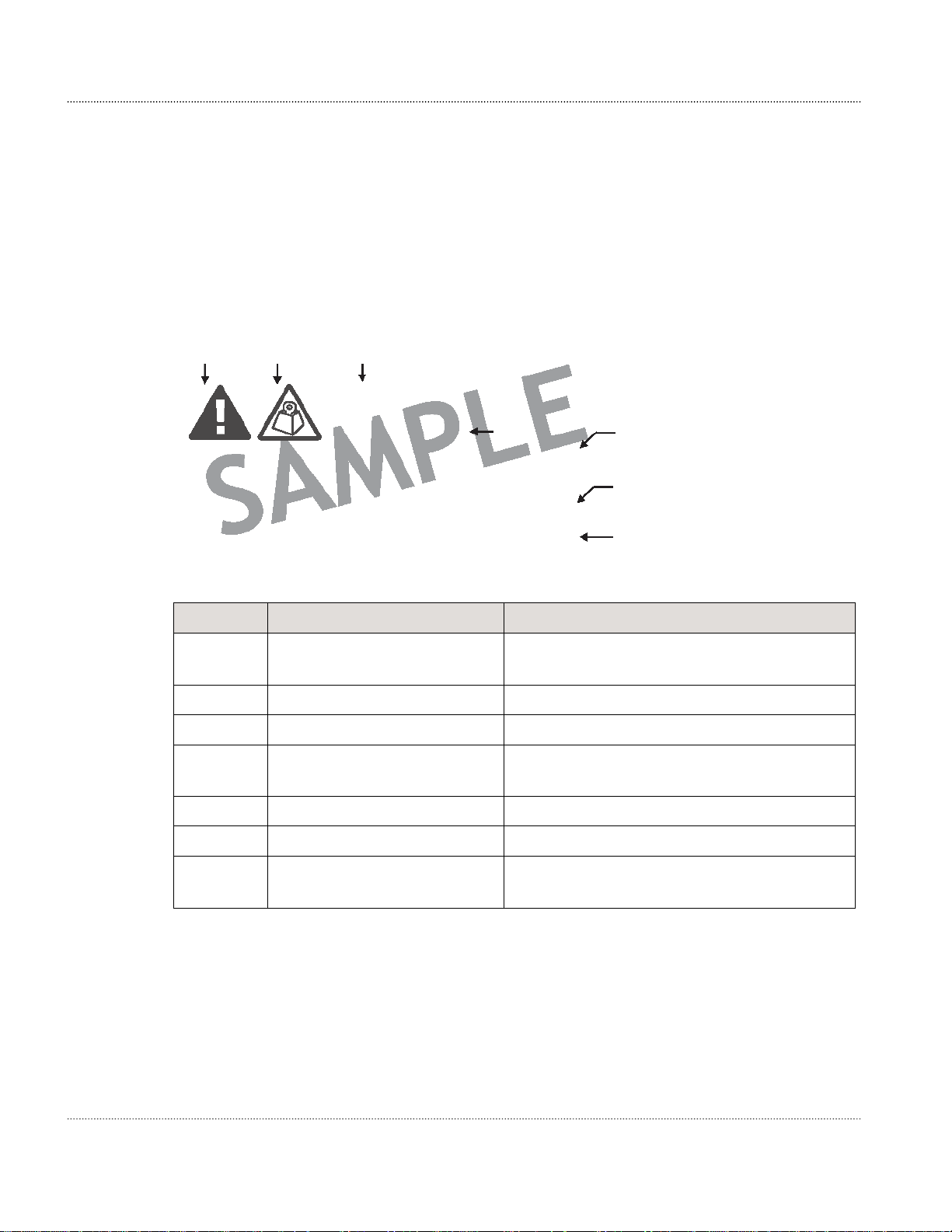
General structure
Safety statements include the following structural elements:
B C D
CAUTION
Lifting hazard
Lifting this equipment by yourself can result in injury
due to the size and weight of the equipment.
Always use three people or a lifting device to transport
and position this equipment. [ABC123]
Item Structure element Purpose
B Safety alert symbol
C Safety symbol Indicates hazard type (optional)
D Signal word Indicates the severity of the hazard
E Hazard type
E F
G
H
Indicates the potential for personal injury
(optional)
Describes the source of the risk of damage
or injury
F Safety message Consequences if protective measures fail
G Avoidance message Protective measures to take to avoid the hazard
H Identifier
1-2 Alcatel-Lucent – Proprietary 9764 MCO B13 LTE 2x5W
Use pursuant to applicable agreements 3MN-01651-0002-RJZZA
The reference ID of the safety
statement (optional)
Issue 0.05 January 2013
Page 11
Safety statements Structure of safety statements
Signal words
The signal words identify the hazard severity levels as follows:
Signal word Meaning
DANGER
Indicates an extremely hazardous situation which, if not avoided,
will result in death or serious injury.
WARNING
Indicates a hazardous situation which, if not avoided, could result
in death or serious injury.
CAUTION
Indicates a hazardous situation which, if not avoided, could result
in minor or moderate injury.
NOTICE Indicates a hazardous situation not related to personal injury.
9764 MCO B13 LTE 2x5W Alcatel-Lucent – Proprietary 1-3
3MN-01651-0002-RJZZA Use pursuant to applicable agreements
Issue 0.05 January 2013
Page 12

Safety statements Safety
Safety
General precautions for installation procedures
WARNING
Failure to observe these safety precautions may result in personal
injury or damage to equipment.
Read and understand all instructions.
Follow all warnings and instructions marked on this product.
Installation and maintenance procedures must be followed and performed
by trained personnel only.
The equipment must be provided with a readily accessible disconnect device
as part of site preparation.
Grounding and circuit continuity is vital for safe operation of the
equipment. Never operate the equipment with grounding/bonding conductor
disconnected.
Install only equipment identified in the product's installation manual. Use of
Use caution when installing or modifying telecommunications equipment.
Before servicing, disconnect power input to reduce the risk of energy
For continued protection against risk offire, all fuses used in this product
Never install telecommunications equipment during a lightning storm or
when conditions are wet.
Never touch uninsulated wiring or terminals carrying direct current or
Never spill liquids of any kind on the product.
To reduce the risk of an electrical shock, do not disassemble the product.
other equipment may result in an improper connection which could lead to
fire or injury.
hazards.
must be replaced only with fuses of the same type and rating.
ringing current, and never leave this wiring exposed. Protect and tape
uninsulated wiring and terminals to avoid risk offire, electrical shock, and
injury to personnel.
Opening and removing covers and/or circuit boards may expose you to
dangerous voltages or other risks. Incorrect reassembly can cause electrical
shock when the unit is subsequently used.
for PERMANENTLY CONNECTED EQUIPMENT, a readily accessible
disconnect device must be incorporated external to the equipment.
1-4 Alcatel-Lucent – Proprietary 9764 MCO B13 LTE 2x5W
Use pursuant to applicable agreements 3MN-01651-0002-RJZZA
Issue 0.05 January 2013
Page 13
Safety statements Safety - specific hazards
Safety - specific hazards
DANGER
Electric-shock hazard
Working in severe weather can result in personal injury or death
and damage to the equipment.
Never install or perform maintenance during severe weather (high winds, lightning,
blizzards, hurricane etc.).
DANGER
Noxious-substance hazard
Use of unspecified cleaning agents can result in
personal injury. Use only specified cleaning agents. Never use
flammable solvents.
Always ensure there is adequate ventilation in the work area and
wear the appropriate personal protective equipment.
CAUTION
RF hazard
RF exposure in excess of applicable limits can result in personal injury.
Metro Cells are designed and installed in order that they are compliant with the
international exposure guidelines laid down by the International Commission
on Non-Ionizing Radiation Protection (ICNIRP).
For all staff that are required to work in close proximity to the equipment, for
example maintenance personnel, contact with the antenna should be avoided. No such
persons shall stay in front of the product at a distance of less than 8 cm.
No other persons shall stay in front of the product at a distance of less
than 22 cm.
WARNING
Electric-shock hazard
Some parts of all electrical installations are energized. Failure to observe this fact and
the safety warnings may lead to bodily injury and property damage.
For this reason, only trained and qualified personnel (electrical workers as defined in
IEC 60215 + A1 or EN 60215) may install or service the installation.
9764 MCO B13 LTE 2x5W Alcatel-Lucent – Proprietary 1-5
3MN-01651-0002-RJZZA Use pursuant to applicable agreements
Page 14
Safety statements Safety - specific hazards
WARNING
Electric-shock hazard
The power supply lines to the network element are energized. Contact
with parts carrying voltage can cause health problems, possibly including death, even
hours after the event.
Open and lockout the load disconnect switch in the distribution box to completely
de-energize the network element.
WARNING
Electric-shock hazard
This product may be connected to an AC main power supply and may contain an internal
battery supply. Disconnecting one power source may not de-energize the system, and can
lead to serious injury.
Disconnect and lock out the AC main power supply, ifpresent, and the internal battery
supply, ifpresent, before servicing the equipment.
CAUTION
Electric-shock hazard
DOUBLE POLE/NEUTRAL FUSING
A fuse is used in the neutral of single-phase equipment either permanently connected or
provided with a non-reversible plug. After operation of the fuse, parts of the equipment
that remain energized might represent a hazard during servicing.
Failure to observe this fact and the safety warnings may lead to bodily injury and
property damage.
CAUTION
Hot-surface hazard
The surfaces of the MCO can become hot enough to cause burns on unprotected skin. On
the product label, the universal symbol for Hot Surface (shown here) emphasizes this
hazard.
Before handling the unit, wait until its surfaces have cooled and, where the following
conditions apply, ensure that it is mounted out of the public's reach.
For installations in ambient temperatures exceeding 46° C, surface temperature may
exceed 70° C. In these situations, this equipment is intendedfor installation where access
is restricted to only qualified service personnel.
1-6 Alcatel-Lucent – Proprietary 9764 MCO B13 LTE 2x5W
Use pursuant to applicable agreements 3MN-01651-0002-RJZZA
Issue 0.05 January 2013
Page 15

Safety statements Safety - specific hazards
WARNING
Fall hazard
Falls can occur when working at heights resulting in serious personal
injury or death.
To prevent a fall when working at heights (ladder, scaffold, manlift, roof etc.) follow
safe work practices and wear appropriate fall protection equipment.
NOTICE
Condensation
Sudden changes in the weather may lead to the formation of condensation on
components. Operating the unit when condensation moisture is present can destroy the
unit.
Units which show signs of condensation must be dried before installation.
NOTICE
Tools
Tools left in the working area can cause short circuits during operation which can lead
to the destruction of units.
Make sure after finishing your work that no tools, testing equipment, flashlights, etc.,
have been left in or on the equipment.
9764 MCO B13 LTE 2x5W Alcatel-Lucent – Proprietary 1-7
3MN-01651-0002-RJZZA Use pursuant to applicable agreements
Issue 0.05 January 2013
Page 16

Safety statements Product safety
Product safety
Equipment safety
Safety information for this equipment can be found on various Caution, Warning, Danger,
information labels or instructions affixed to or included with the product or included
within this document. Informational and cautionary labels may appear near the item they
address or may be grouped in a single location on the equipment. Warnings are typically
adjacent to the hazard that is noted on the label. The instructions, cautions and warnings
found on these labels must be understood and observed by all personnel involved with the
equipment installation and maintenance.
1-8 Alcatel-Lucent – Proprietary 9764 MCO B13 LTE 2x5W
Use pursuant to applicable agreements 3MN-01651-0002-RJZZA
Issue 0.05 January 2013
Page 17

2 Product overview
Overview
Purpose
This chapter provides an overview of the Alcatel-Lucent lightRadioTM Metro
Cell Outdoor 2x5W B13 LTE product.
Contents
Functional description
Physical description
2-2
2-3
9764 MCO B13 LTE 2x5W Alcatel-Lucent – Proprietary
3MN-01651-0002-RJZZA Use pursuant to applicable agreements
Issue 0.05 January 2013
2-1
Page 18

Product overview Functional description
Functional description
General description
A Metro Cell is a public wireless access node that uses licensed spectrum with
substantially lower coverage and serving a smaller number of users than Macro Cells. The
Alcatel-Lucent 9764 lightRadioTM Metro Cell Outdoor 2x5W B13 LTE specified here
supports 3GPP Band 13 (DL 746-756MHz, UL 777-787MHz ).
The Metro Cell is for targeted for high user density locations where additional capacity is
required or even in areas where increased wireless coverage is needed at short notice. The
product can be deployed by mobile operators to provide a transparent outdoor capacity
layer to complement the macro cell “umbrella” coverage layer.
Product features and attributes
The product capabilities in this release are:
Supports Band 13 Upper C block (DL 746-756MHz; UL 777-787MHz)
Utilizes 115V or 220V AC
Supports 2x2 MIMO transmit/receive configurations (2 transmit and 2 receive
streams)
Supports traffic backhauled through the standard IP network. The default backhaul
connection from the Access Point is via one Gigabit Ethernet 1000Base-X (SFP
module) port (optical or electrical)
Antenna configuration:
– Omnidirectional antennas mounted directly onto transmit/receive connectors
– Antenna cables mounted directly onto transmit/receive connectors for connection to
Utilizes GPS Synchronization
Utilizes GPS Synchronization
Front access installation and service.
Installation options
The Metro Cell is designed to be used outdoors can be installed using the following
options:
pole mounted
remote antenna site.
wall mounted
floor mounted (via floor stand)
2-2 Alcatel-Lucent – Proprietary 9764 MCO B13 LTE 2x5W
Use pursuant to applicable agreements 3MN-01651-0002-RJZZA
Issue 0.05 January 2013
Page 19
Product overview Physical description
Physical description
Product overview
The Metro Cell Outdoor is housed in a weatherized, rated Type 4 and/or IP65 outdoor,
passively cooled enclosure containing the following active components:
Backhaul/Digital/Radio board (DA Board)
RF Filter
Power board
Power Amplifier board
The Metro Cell Outdoor 2x5W product is shown in the following figures:
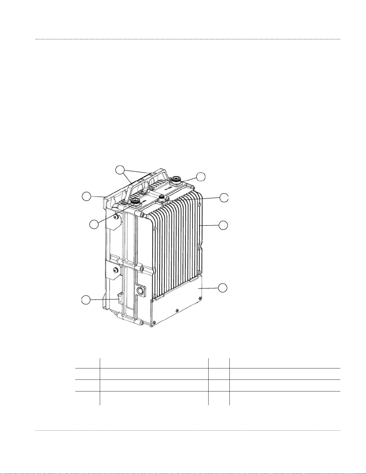
Figure 2-1 Metro Cell Outdoor (front/top view)
5
4
3
6
4
7
1
2
Legend:
1 Metro Cell Outdoor 2x5W 5 Metro Cell mounting bracket
2 Metro Cell connection panel 6 Metro Cell lifting points
3 Metro Cell Outdoor grounding point 7 GPS Antenna connector
4 RF Antenna connector(s)
9764 MCO B13 LTE 2x5W Alcatel-Lucent – Proprietary 2-3
3MN-01651-0002-RJZZA Use pursuant to applicable agreements
Issue 0.05 January 2013
Page 20

Product overview Physical description
Figure 2-2 Metro Cell Outdoor (front/bottom view)
4
3
2
1
Legend:
Power and electrical
1
ground cable entry point
Backhaul cable entry point (via conduit)
2
Backhaul cable entry
3
point (via Pflitch grand)
Junction box cable entry point
4
The physical dimensions of the
Metro Cell Outdoor (excluding solar cover, antenna, and mounting hardware) are:
Dimension Value
Height x Width x Depth
400mm x 270mm x 176mm
(15.8 x 10.6 x 6.9 inches)
Volume 18L
Weight 18 kg (39.6 lbs).
2-4 Alcatel-Lucent – Proprietary 9764 MCO B13 LTE 2x5W
Use pursuant to applicable agreements 3MN-01651-0002-RJZZA
Issue 0.05 January 2013
Page 21
Product overview Physical description
Connection interfaces
The following figure shows the connection interfaces for antenna, power and
backhaul cabling on the Metro Cell Outdoor.
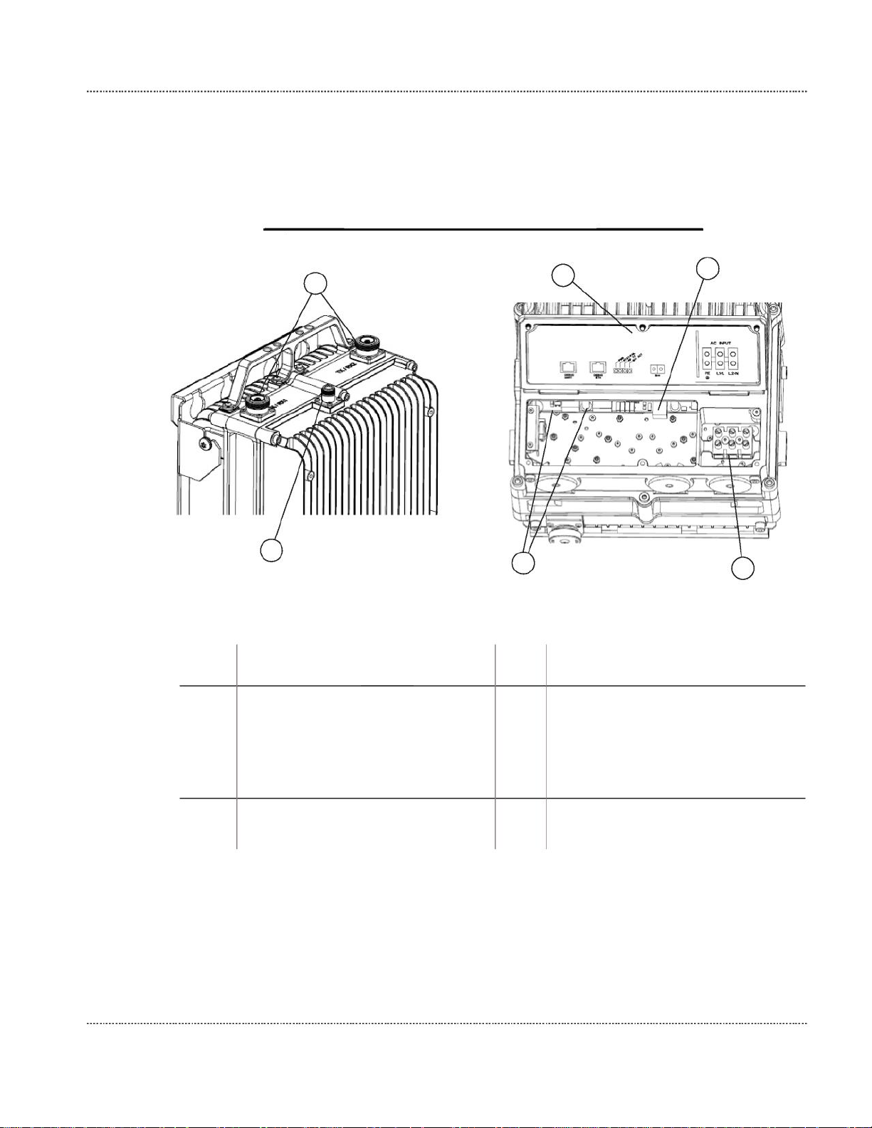
Figure 2-3 Metro Cell connection interfaces
Top of unit Bottom of unit
1
6
5
Legend:
1
2
3
2
RF Antenna connectors
( 7/16” DIN male)
GPS Antenna connector (N Type
male)
RJ-45 connection points (Debug
UART and Debug ETH)
34
4
Power and grounding terminal block
5 SFP port supporting either:
1000Base-X GigE optical
transceiver
10/100/1000Base-T electrical
transceiver
6
Cable connection cover
9764 MCO B13 LTE 2x5W
3MN-01651-0002-RJZZA
Issue 0.05 January 2013
Alcatel-Lucent – Proprietary 2-5
Use pursuant to applicable agreements
Page 22

Product overview Physical description
Figure 2-4 Metro Cell connection cover label
Connectors provided are external and waterproof. They are also protected by surge and
lightning arrestor.
Power supply
The Metro Cell requires 115 VAC or 220 VAC nominal (60 Hz, Single Phase).
RF Antenna
GPS Antenna
The Meto Cell does not contain surge protection, therefore external surge protection is
required. Surge protection requirements are:
First level (no damage to equipment, no service interruption): +/-2KV, 1.2/50us; 1KA,
8/20us; 5 repetitions each polarity from Line to Neutral, Line to Ground, and Neutral
to Ground
Second level (no safety hazard): +/-6KV, 1.2/50us; 3KA, 8/20us; 1 repetition each
polarity from Line to Neutral, Line to Ground, and Neutral to Ground
The Metro Cell Outdoor has two external Rx/Tx antenna connectors (7/16” DIN male)
located on the top the device allowing for the following antenna connection options:
+2dBi Omnidirectional antennas mounted directly onto transmit/receive connectors
Antenna cables mounted directly onto transmit/receive connectors for connection to
remote antenna site.
The Metro Cell Outdoor has an external GPS antenna connector located on the top the
device allowing for the GPS antenna connection options:
GPS antenna mounted directly on the product
GPS antenna cable connection for cabling to a remote GPS antenna site.
2-6 Alcatel-Lucent – Proprietary 9764 MCO B13 LTE 2x5W
Use pursuant to applicable agreements 3MN-01651-0002-RJZZA
Issue 0.05 January 2013
Page 23

Product overview Physical description
Debug interface
When the external connection interface cover is open a number of LEDs are available for
debugging purposes.
LED Label Description Color
LED1 PWR Power Green
LED2 STAT/FAIL Fault Red/Yellow/Green
LED3 RF TX RF TX active Red/Yellow/Green
LED4 B/H ACT Backhaul active Red/Yellow/Green
Additional LEDs for Ethernet connectivity status are available at the SFP and RJ-45
connectors.
Product labelling
A product label provides the following information:
Model name
Part number
Serial number
MAC address
CE Approval marking
Environmental marking (WEEE/ROHS) applicable to the device.
Product base items and configuration
The Metro Cell Outdoor product is delivered with the following base items:
Metro Cell Outdoor 2x5W 700 MHz unit
Wall mount bracket
Ancillary orderable items
In addition to the Metro Cell Outdoor base items the following ancillary and variable
items can be ordered depending on the product configuration and deployment scenario:
RF Antenna:
– Directly mounted +2dBi Omnidirectional Antennas
– RF Antenna cables for cabling to a remote antenna site
GPS Antenna:
– Directly mounted GPS Antenna with support brackets
– GPS Antenna cable for cabling to a remote GPS Antenna site
9764 MCO B13 LTE 2x5W Alcatel-Lucent – Proprietary 2-7
3MN-01651-0002-RJZZA Use pursuant to applicable agreements
Issue 0.05 January 2013
Page 24

Product overview Physical description
Pole mounting kit
Wall mounting kit
Floor mounting kit
Solar shield installation kit
“Pflitsch” cable gland kit
2-8 Alcatel-Lucent – Proprietary 9764 MCO B13 LTE 2x5W
Use pursuant to applicable agreements 3MN-01651-0002-RJZZA
Issue 0.05 January 2013
Page 25

3 Installation
Overview
Purpose
This chapter provides general instructions for mounting and grounding the Metro Cell.
Contents
Installation 3-2
Pre-installation information 3-3
Procedure 3-1: To mount the hardware to a wall 3-5
Pole mount installation overview 3-13
Procedure 3-2: To mount hardware to pole with pole bands 3-15
Procedure 3-3: To mount hardware to pole with through pole bolts 3-18
Procedure 3-4: To mount hardware to pole with back-to-back pole brackets 3-21
Procedure 3-5: To install the Metro Cell on pole weldment assemblies 3-24
Procedure 3-6: To mount the hardware to a floor stand 3-26
Cabling 3-30
Procedure 3-7: Metro Cell cabling 3-31
Post-installation activities 3-39
Procedure 3-8: Close faceplate cover 3-40
Procedure 3-9: Install the solar shield 3-41
Procedure 3-10: Post installation activities and checks 3-42
9764 MCO B13 LTE 2x5W Alcatel-Lucent – Proprietary 3-1
3MN-01651-0002-RJZZA Use pursuant to applicable agreements
Issue 0.05 January 2013
Page 26

Installation
Installation
Installation
Overview
Purpose
This sections contains instructions for mounting the Metro Cell.
Contents
Pre-installation information
Procedure 3-1: To mount the hardware to a wall
Pole mount installation overview
Procedure 3-2: To mount hardware to pole with pole bands
Procedure 3
-3: To mount hardware to pole with through pole bolts
Overview
3-3
3-5
3-13
3-15
3-18
Procedure 3-4: To mount hardware to pole with back-to-bac k pole brackets
Procedure 3-5: To install the Metro Cell on pole weldment assemblies
Procedure 3-6: To mount the hardware to a floor stand
3-21
3-24
3-26
3-2 Alcatel-Lucent – Proprietary
Use pursuant to applicable agreements
9764 MCO B13 LTE 2x5W
3MN-01651-0002-RJZZA
Issue 0.05 January 2013
Page 27

Installation Pre-installation information
Installation
Pre-installation information
Product delivery contents
The following items are supplied with the Metro Cell:
Wall mounting kit
Note: The wall mounting bracket, also referred as the main bracket, is required for all
mounting options.
Variable parts and ancillary items
In addition to the standard delivered parts, the following variable and ancillary items are
supplied as needed:
RF Antennas:
– Pair of directly mounted +2dBi omnidirectional antennas
– RF antenna cables for cabling to a remote antenna site
– External GPS antenna:
– Directly mounted GPS Antenna with support brackets
– GPS antenna cable for cabling to a remote GPS antenna site
Pole mounting kit:
– With pole band bracket for small diameter pole
– With through pole bracket for large diameter pole
– With back-to-back bracket for 50 mm diameter pole
Solar shield installation kit
“Pflitsch” cable gland kit
Installation tools required
The following tools may be used during installation:
Tool Purpose
10 mm socket Grounding bolts
14 mm socket Unistrut mounting bolts
17 mm socket Floor stand or pole mount bracket mounting bolts
Flat blade
screwdriver
AC input terminal block
T20 Torx driver AC input protective cover securing screw
T25 Torx driver Mounting screws for faceplate cover solar shield and solar shield
9764 MCO B13 LTE 2x5W Alcatel-Lucent – Proprietary 3-3
3MN-01651-0002-RJZZA Use pursuant to applicable agreements
Issue 0.05 January 2013
Page 28

Installation Pre-installation information
Installation
Tool Purpose
T25 secure Torx
I/O panel cover
driver
T40 secure Torx
Metro to wall mount bracket securing screws
driver
11/4” (33 mm) torque
DIN 7/16 connector
wrench
3/4” torque wrench N-type connector
RF jumper stripping
tool
PPC tool kit
Level or plumb line Ensuring the Metro Cell is level
3-4 Alcatel-Lucent – Proprietary 9764 MCO B13 LTE 2x5W
Use pursuant to applicable agreements 3MN-01651-0002-RJZZA
Issue 0.05 January 2013
Page 29

Installation Procedure 3-1: To mount the hardware to a wall
Installation
Procedure 3-1: To mount the hardware to a wall
Purpose
This topic describes the procedures to be followed when installing the Metro Cell onto a
solid concrete wall. The Metro Cell can be mounted either directly onto the wall, or
indirectly using the Unistrut system.
Prerequisites
A site survey has been conducted and a location for the device has been selected that is
both central to the public space and elevated, to maximize coverage.
Before installation begins, ensure that the following are in place:
Internet service is available for backhaul.
The fiber optic Ethernet cable has been routed and is in place.
The ground cable has been routed and is in place.
Site specific fixing materials (screws, washers, wall plugs) are available for wall
mounting the Metro Cell.
120-240 V AC power is available
Anchors or Unistrut in place on the wall
Wall mount brackets
Various building materials and construction methods dictate that the Metro Cell must be
fastened to the wall with appropriate mounting hardware. It is the responsibility of the
customer to provide any necessary support material and structures to ensure that the
installation will be in compliance with Building Officials and Code Administrators
(BOCA), Uniform Building Code (UBC), and all local codes.
The following figure illustrates the wall mounting bracket (also referred to as the main
bracket) that is required to mount the Metro Cell onto a wall:
9764 MCO B13 LTE 2x5W Alcatel-Lucent – Proprietary 3-5
3MN-01651-0002-RJZZA Use pursuant to applicable agreements
Issue 0.05 January 2013
Page 30

Installation Procedure 3-1: To mount the hardware to a wall
Installation
Figure 3-1 Wall mounting bracket (main bracket)
Wall mounting bracket hole pattern
The following graphic shows the wall mounting bracket hole pattern for the Metro Cell.
The dimension shown are in millimeters and inches:
3-6 Alcatel-Lucent – Proprietary 9764 MCO B13 LTE 2x5W
Use pursuant to applicable agreements 3MN-01651-0002-RJZZA
Issue 0.05 January 2013
Page 31

Installation Procedure 3-1: To mount the hardware to a wall
Installation
Figure 3-2 Wall mounting bracket hole pattern
199.8 mm
(7.87 in)
82.4 mm
(3.24 in)
350 mm
(13.78 in)
Indirect wall mounting bracket (Unistrut)
You can mount the Metro Cell either directly onto a wall, or to a Unistrut wall mounting
bracket. If a Unistrut wall mounting bracket is used, it must have been attached to the
wall during site preparation.
9764 MCO B13 LTE 2x5W Alcatel-Lucent – Proprietary 3-7
3MN-01651-0002-RJZZA Use pursuant to applicable agreements
Issue 0.05 January 2013
Page 32

Installation Procedure 3-1: To mount the hardware to a wall
Installation
The following figure shows the Unistrut wall mounting bracket:
Figure 3-3 Unistrut wall mounting bracket
Before you begin
Note: Record the 11 digit serial number before mounting the Metro Cell.
Install Metro Cell directly onto wall
WARNING
Fall hazard
Falls can occur when working at heights resulting in serious personal
injury or death.
To prevent a fall when working at heights (ladder, scaffold, manlift, roof etc.) follow
safe work practices and wear appropriate fall protection equipment.
3-8 Alcatel-Lucent – Proprietary 9764 MCO B13 LTE 2x5W
Use pursuant to applicable agreements 3MN-01651-0002-RJZZA
Issue 0.05 January 2013
Page 33

Installation Procedure 3-1: To mount the hardware to a wall
Installation
To mount the Metro Cell directly onto a wall or flat surface, perform the following steps:
1 Using the hole pattern of the wall bracket as a as a guide, ensure that the anchor locations
are correct. See Figure 3-2, “Wall mounting bracket hole pattern” (p. 3-7).
Check the horizontal position with a spirit level.
2 Attach the main bracket to the wall using appropriate screw fixings.
Note: Depending on the wall the device must be mounted to, different screw fixings
might be needed. After site survey these mounting accessories must be procured
locally.
3 Insert the appropriate screws into the upper two bolt holes of the Metro Cell, but do not
tighten them.
4 Using the lifting point on the Metro Cell, align the bolt holes on the Metro Cell with the
bolt holes in the main bracket. Do this by hanging the Metro Cell from the upper bolt
holes in the main bracket, and then swing the Metro Cell down to align the lower bolt
holes. The bolt holes are shown in the following figure:
9764 MCO B13 LTE 2x5W Alcatel-Lucent – Proprietary 3-9
3MN-01651-0002-RJZZA Use pursuant to applicable agreements
Issue 0.05 January 2013
Page 34

Installation
Installation
Procedure 3-1: To mount the hardware to a wall
Figure 3-4 Bolt holes and lifting point on the Metro Cell
Lifting point
Upper bolt hole
Lower bolt hole
Important! When lifting the Metro Cell, do not rest the bottom side on the ground.
5 Insert the appropriate screw fixings into the lower bolt holes and tighten all four screw
fixings using a T40 secure Torx driver.
6 After mounting the Metro Cell to the wall, the cables must be connected. Continue with
Procedure 3-7: “Metro Cell cabling” (p. 3-31).
END O F STEPS
3-10 Alcatel-Lucent – Proprietary
Use pursuant to applicable agreements
9764 MCO B13 LTE 2x5W
3MN-01651-0002-RJZZA
Issue 0.05 January 2013
Page 35

Installation Procedure 3-1: To mount the hardware to a wall
Installation
Install Metro Cell onto Unistrut bracket
CAUTION
Personal Injury
The bolts on the Metro Cell can pinch and damage
your fingers. Keep fingers clear when lowering the Metro Cell
into position.
To mount the Metro Cell onto a Unistrut wall mounting bracket, perform the following
procedure:
1 Attach the main bracket to the Unistrut bracket using four M10 (3/8 in) hex bolts with
flatwasher, lockwasher and, springnut. Level and properly torque the bolts.
2 Loosely attach the two side top M10 hex bolts, flat washers, and lock washers to the Metro
Cell as supplied with the wall mounting kit. Do not tighten yet. Tape the washers to the
heads of the bolts.
Important! When lifting the Metro Cell, do not rest the bottom side on the ground.
3 Lift the Metro Cell into position. Position to the M10 hex bolts on the Metro Cell in the
top mounting slots of the main bracket. Do not tighten the bolts yet.
4 Install the two bottom side M10 hex bolts, flat washers, and lock washers through the
main bracket.
Remove tape from top hardware.
5 If necessary, level brackets to insure that the Metro Cell will be mounted level. Use a
level to level the top of the Metro Cell.
6 Tighten all the M10 hex bolts and use a torque wrench to tighten all the nuts 32.2 Nm (25
ft-lb).
7 Install tamper-proof screws.
9764 MCO B13 LTE 2x5W Alcatel-Lucent – Proprietary 3-11
3MN-01651-0002-RJZZA Use pursuant to applicable agreements
Issue 0.05 January 2013
Page 36

Installation Procedure 3-1: To mount the hardware to a wall
Installation
8 After mounting the Metro Cell to the Unistrut bracket, the cables must be connected.
Continue with Procedure 3-7: “Metro Cell cabling” (p. 3-31).
E ND O F STEPS
3-12 Alcatel-Lucent – Proprietary 9764 MCO B13 LTE 2x5W
Use pursuant to applicable agreements 3MN-01651-0002-RJZZA
Issue 0.05 January 2013
Page 37

Installation Pole mount installation overview
Installation
Pole mount installation overview
Overview
This section describes the procedures to be followed when installing the Metro Cell on a
pole.
There are three types of pole mounting installation:
Pole band brackets for small pole diameters
Through pole brackets for large pole diameters
Back to back mounting brackets for small pole diameters
Pole mounting brackets
This topic shows the types of brackets that can be sued to mount a Metro Cell to a
pole. Pole band bracket
For pole diameters from 50 mm to 152 mm, pole band brackets are required.
Figure 3-5 Pole band bracket
Pole band bracket
Through pole bracket
For pole diameters from 50 mm to 152 mm, through pole brackets are required.
9764 MCO B13 LTE 2x5W Alcatel-Lucent – Proprietary 3-13
3MN-01651-0002-RJZZA Use pursuant to applicable agreements
Issue 0.05 January 2013
Page 38

Installation Pole mount installation overview
Installation
Figure 3-6 Through pole bolt
Through pole bracket
Back to back mounting brackets
For pole diameters from 50 mm to 152 mm, back to back mounting brackets can be used.
Figure 3-7 Back to back mounting bracket
Bact-to-back pole bracket
3-14 Alcatel-Lucent – Proprietary 9764 MCO B13 LTE 2x5W
Use pursuant to applicable agreements 3MN-01651-0002-RJZZA
Issue 0.05 January 2013
Page 39

Installation Procedure 3-2: To mount hardware to pole with pole bands
Installation
Procedure 3-2: To mount hardware to pole with pole bands
Purpose
This section describes the procedures to be followed when installing the Metro Cell on a
152 (6 in) mm to 380 mm (15 in) diameter pole with pole brackets.
WARNING
Fall hazard
Falls can occur when working at heights resulting in serious personal
injury or death.
To prevent a fall when working at heights (ladder, scaffold, manlift, roof etc.) follow
safe work practices and wear appropriate fall protection equipment.
Before you begin
The following mounting hardware is required to mount up to the Metro Cell on a pole:
Pole mounting bands (qty. 2)
Pole brackets (qty. 2)
Main bracket
M10 bolts, lock washers, and flat washers (qty. 4).
Measure and mark pole and pole bands
Perform the following procedure to measure and mark the upper and lower pole band
locations and the pole bands.
1 Use a tape measure to determine and mark the position of the upper and lower pole bands
350 mm (13.8 in) apart for Metro Cells. Refer to specific cell site engineering information
for measurement details.
2 Measure the circumference (distance around the pole) at the heights of the bands to be
installed.
3 Measure the distances you calculated in Step 2 on the pole bands from the fixed retainer
extrusion.
4 Mark the bands at that point.
9764 MCO B13 LTE 2x5W Alcatel-Lucent – Proprietary 3-15
3MN-01651-0002-RJZZA Use pursuant to applicable agreements
Issue 0.05 January 2013
Page 40

Installation Procedure 3-2: To mount hardware to pole with pole bands
Installation
5 Use a nail and a chalked plumb line or plumb bob to mark a vertical line on the pole so
that the upper and lower brackets will be aligned.
E ND O F STEPS
Place weldment(s) on pole bands
Perform the following procedure to place the pole weldment on the upper and lower pole
bands.
1 Remove the sliding retainer extrusion from the pole bands.
2 Thread the weldment(s) onto the pole bands.
3 Replace the sliding retainer extrusion on each pole band so that the beveled ends of
extrusion faces the open end of the band.
E ND O F STEPS
Bend the bands
Perform the following procedure to bend the upper and lower pole bands.
1 Bend the bands at the previously marked spot so that the pointed end of the band will be
inside the band after installation.
2 Strike the bands with a hammer to create a sharp radius that allows the retainer to lock
into place.
3 Make a 90 degree bend at the base of each retainer extrusion to allow the retainers and
carriage bolt to properly align and lock into place.
E ND O F STEPS
3-16 Alcatel-Lucent – Proprietary 9764 MCO B13 LTE 2x5W
Use pursuant to applicable agreements 3MN-01651-0002-RJZZA
Issue 0.05 January 2013
Page 41

Installation Procedure 3-2: To mount hardware to pole with pole bands
Installation
Install pole bands on pole
Perform the following procedure to install the upper and lower pole bands on the pole.
1 Place the pole bands around the pole at the determined height.
2 Insert the carriage bolt through both retainers, making sure that the head of bolt properly
locks into the fixed retainer.
3 Install the nut and tighten it just enough so that the band and weldment(s) maintain their
position on the pole. Do not fully tighten the nut.
4 Adjust the position of the weldment(s) so that they are centered on the horizontal and
vertical lines marked on the pole. Use a level or plumb line to verify that the weldment(s)
are level.
5 Adjust the bands so that they are snug and do not slide down pole (the bands may need
adjustment when attaching the main bracket).
6 Attach main bracket using four M10 hex bolts, lockwasher, and flatwasher. Use a level or
plumb line to verify that the brackets are level.
7 Torque each bolt 32.2 Nm (25 ft lb.).
8 Fully tighten each band.
E ND O F STEPS
9764 MCO B13 LTE 2x5W Alcatel-Lucent – Proprietary 3-17
3MN-01651-0002-RJZZA Use pursuant to applicable agreements
Issue 0.05 January 2013
Page 42

Installation Procedure 3-3: To mount hardware to pole with through
Installation pole bolts
Procedure 3-3: To mount hardware to pole with through pole
bolts
Purpose
This section describes the procedures to follow when installing the Metro Cell on a
pole with M16 (5/8 in) through bolts.
Mounted bracket
The following graphic shows a pair of through pole brackets mounted on a wooden pole:
Figure 3-8 Through pole brack ets mounted on a wooden pole
3-18 Alcatel-Lucent – Proprietary 9764 MCO B13 LTE 2x5W
Use pursuant to applicable agreements 3MN-01651-0002-RJZZA
Issue 0.05 January 2013
Page 43

Installation Procedure 3-3: To mount hardware to pole with through
Installation pole bolts
WARNING
Fall hazard
Falls can occur when working at heights resulting in serious personal
injury or death.
To prevent a fall when working at heights (ladder, scaffold, manlift, roof etc.) follow
safe work practices and wear appropriate fall protection equipment.
Before you begin
The following mounting hardware is required to mount the Metro Cell on a pole using
through pole bolts:
16 mm (5/8 inch) through bolts with nuts (qty. 2)
Pole weldment (qty. 2)
Main bracket
M10 bolts, lock washers, and flat washers (qty. 4)
Curved washers (qty. 2).
Measure and mark pole and attach weldments
Perform the following procedure to measure and mark the upper and lower through bolt
locations and attach weldments.
1 Use a tape measure to determine and mark the position of the upper and lower through
bolts on the pole. Refer to specific cell site engineering information for measurement
details.
2 Mark and drill two 19 mm (0.75 in) holes at a distance of 540 mm (21.26 in) apart.
Job aid Use a nail and a chalked plumb line or plumb bob to mark a vertical line on
the pole so that the upper and lower weldments will be aligned.
3 Line up the upper pole weldment and insert a M16 (5/8) through bolt with washer through
the center hole and loosely attach to pole at the other end, using M16 (5/8”) curved
washer and hex nut.
4 Repeat previous step for the lower bracket.
5 Pre-install four M10 hex bolts, lock washers and flat washers.
9764 MCO B13 LTE 2x5W Alcatel-Lucent – Proprietary 3-19
3MN-01651-0002-RJZZA Use pursuant to applicable agreements
Issue 0.05 January 2013
Page 44

Installation Procedure 3-3: To mount hardware to pole with through
Installation pole bolts
Important! Do not tighten yet. The main bracket of the Metro Cell will need to be
hung on these four bolts.
E ND O F STEPS
How to continue
Continue hardware installation with the installation of the Metro Cell on the pole
weldment assemblies: Procedure 3-5: “To install the Metro Cell on pole weldment
assemblies” (p. 3-24)
3-20 Alcatel-Lucent – Proprietary 9764 MCO B13 LTE 2x5W
Use pursuant to applicable agreements 3MN-01651-0002-RJZZA
Issue 0.05 January 2013
Page 45

Installation
Installation
Procedure 3-4: To mount hardware to pole with
back-to-back pole brackets
Procedure 3-4: To mount hardware to pole with back-to-back
pole brackets
Purpose
This section describes the procedures to be followed when installing the Metro Cell on
a 50 mm (2 in) to 152 mm (6 in) diameter pole with back-to-back pole brackets.
Mounted bracket
The following graphic shows a pair of back-to-back pole brackets mounted on a pole:
Figure 3-9 Back-to-back pole brackets mounted on a pole
Small pole (back to back)
mounting brackets
Pole
Main bracket
9764 MCO B13 LTE 2x5W
3MN-01651-0002-RJZZA
Issue 0.05 January 2013
Small pole (back to
mounting brackets
Alcatel-Lucent – Proprietary 3-21
Use pursuant to applicable agreements
back)
Page 46

Installation Procedure 3-4: To mount hardware to pole with
Installation back-to-back pole brackets
WARNING
Fall hazard
Falls can occur when working at heights resulting in serious personal
injury or death.
To prevent a fall when working at heights (ladder, scaffold, manlift, roof etc.) follow
safe work practices and wear appropriate fall protection equipment.
Before you begin
The following mounting hardware is required to mount up to the Metro Cell on a small
diameter pole:
Pole mounting brackets (qty. 2x2)
300 mm M10 hex nut bolts (qty. 4)
80 mm M10 hex nut bolts (qty. 4)
Lock washers (qty. 12), flat washers (qty. 12), for M10 bolts
M10 nuts (qty. 4)
Main bracket
Measure and mark pole and attach pole brackets
1 Use a tape measure to determine and mark the position of the upper pole bracket.
2 Attach the upper pole bracket to the main bracket using two 80 mm long M10 hex bolts,
lock washers, flat washers. Insert bolts through inner holes of the main bracket.
Repeat for the lower pole bracket.
3 Insert a 300 mm M10 hex bolt, equipped with lock washer and flat washer, through the
upper left-most hole in the bracket, through the attached pole bracket.
4 Insert opposite bracket over threaded portion of the 300 mm bolt, and secure with flat
washer, lockwasher, and hex nut.
5 Adjust to estimated pole diameter.
6 Lift the subassembly to the marked height.
3-22 Alcatel-Lucent – Proprietary 9764 MCO B13 LTE 2x5W
Use pursuant to applicable agreements 3MN-01651-0002-RJZZA
Issue 0.05 January 2013
Page 47

Installation Procedure 3-4: To mount hardware to pole with
Installation back-to-back pole brackets
7 Insert 300 mm long, M10 hex bolt, lock washer, and flat washer through the right- most
upper hole in main bracket, through the attached pole bracket and the opposite bracket,
and secure with lock washer, flat washer and hex nut.
8 Equally tighten all bolts.
9 Install opposite end of lower pole bracket using 300 mm, M10 long hex bolts, lock
washers, and flat washers.
10 Equally tighten all bolts.
E ND O F STEPS
How to continue
Continue hardware installation with the installation of the Metro Cell: Procedure 3-5:
“To install the Metro Cell on pole weldment assemblies” (p. 3-24)
9764 MCO B13 LTE 2x5W Alcatel-Lucent – Proprietary 3-23
3MN-01651-0002-RJZZA Use pursuant to applicable agreements
Issue 0.05 January 2013
Page 48

Installation Procedure 3-5: To install the Metro Cell on pole weldment
Installation assemblies
Procedure 3-5: To install the Metro Cell on pole weldment
assemblies
Purpose
This section describes the procedures to be followed when installing the Metro Cell to
pole weldment assemblies.
WARNING
Fall hazard
Falls can occur when working at heights resulting in serious personal
injury or death.
To prevent a fall when working at heights (ladder, scaffold, manlift, roof etc.) follow
safe work practices and wear appropriate fall protection equipment.
Before you begin
Site preparation activities must have been completed.
Install Metro Cell on pole weldment assemblies
Perform the following procedure to install the Metro Cell on the mounting hardware.
1 Carefully raise the Metro Cell into position.
2 Loosely attach the two side top M10 hex bolts, flat washers, and lock washers to the
Metro Cell as supplied with the wall mounting kit. Do not tighten yet, install only
halfway. Tape the washers to the bolts.
Note: When lifting the Metro Cell, do not rest the bottom side of the Metro Cell on
the ground.
3 At the upper corners of the Metro Cell, pull the washers to the sides. Position the M10
hex bolts on the Metro Cell in the top mounting slots of the bracket.
4 Install the two bottom side M10 hex bolts, flat washers, and lock washers through the
wall mount bracket.
Remove tape from top hardware.
3-24 Alcatel-Lucent – Proprietary 9764 MCO B13 LTE 2x5W
Use pursuant to applicable agreements 3MN-01651-0002-RJZZA
Issue 0.05 January 2013
Page 49

Installation Procedure 3-5: To install the Metro Cell on pole weldment
Installation assemblies
5 If necessary, level brackets to insure that the Metro Cell will be mounted level. Use a
spirit level to level the top of the Metro Cell.
6 Tighten all the M10 hex bolts and use a torque wrench to tighten all the nuts to 32.2 Nm
(25 ft/lb).
7 Install tamper proof screws.
E ND O F STEPS
9764 MCO B13 LTE 2x5W Alcatel-Lucent – Proprietary 3-25
3MN-01651-0002-RJZZA Use pursuant to applicable agreements
Issue 0.05 January 2013
Page 50

Installation Procedure 3-6: To mount the hardware to a floor stand
Installation
Procedure 3-6: To mount the hardware to a floor stand
Purpose
This topic describes the procedures to install the Metro Cell onto a floor stand.
Floor stand
The following figure shows the floor stand and the positions of the mounting holes.
Figure 3-10 Floor stand and mounting
holes
Mounting holes (1 of 4)
to attach Metro Cell
(main bracket required)
Prerequisites
Ground
(1 of 2)
Floor mounting holes
(1 of 4)
A site survey has been conducted and a location for the device has been selected that is
both central to the public space and elevated in order to maximize coverage.
Before installation begins, ensure that the following are in place:
Before you begin
Internet service is available.
The Ethernet cable has been routed and is in place.
The ground cable has been routed and is in place.
Site specific fixing materials (screws, washers) for mounting the Metro Cell.
Anchor holes for the floor stand have been prepared.
A main bracket is available to attach the Metro Cell to the floor stand.
Page 51

Note: Record the 11 digit serial number before mounting the Metro Cell.
3-26 Alcatel-Lucent – Proprietary 9764 MCO B13 LTE 2x5W
Use pursuant to applicable agreements 3MN-01651-0002-RJZZA
Issue 0.05 January 2013
Page 52

Installation Procedure 3-6: To mount the hardware to a floor stand
Installation
Fix the floor stand to the floor
If the floor stand has not already fixed to the floor at the selected installation location,
perform the following steps to fix the floor stand to the floor:
1 Center the floor stand over the drilled anchor holes.
2 Set and torque the anchor bolts.
E ND O F STEPS
Mount the Metro Cell onto the floor stand
To mount the Metro Cell onto a floor stand perform the following steps:
1 Attach the main bracket to the floor stand using M10 or 3/8 inch bolts, as shown in the
following figure:
9764 MCO B13 LTE 2x5W Alcatel-Lucent – Proprietary 3-27
3MN-01651-0002-RJZZA Use pursuant to applicable agreements
Issue 0.05 January 2013
Page 53

Installation Procedure 3-6: To mount the hardware to a floor stand
Mounting bracket
Floor stands
Installation
Figure 3-11 Floor stand with main bracket attached
Use a level and plumb line to verify that the
bracket is level. Tighten the bolts
using a 17 mm socket wrench.
2 Insert the appropriate screws into the upper two bolt holes of the Metro Cell, but do not
tighten them.
3 Using the lifting point on the Metro Cell, align the bolt holes on the Metro Cell with the
bolt holes in the main bracket. Do this by hanging the Metro Cell from the upper bolt
holes in the main bracket, and then swing the Metro Cell down to align the lower bolt
holes, as shown in the following figure:
3-28 Alcatel-Lucent – Proprietary 9764 MCO B13 LTE 2x5W
Use pursuant to applicable agreements 3MN-01651-0002-RJZZA
Issue 0.05 January 2013
Page 54

Installation
Installation
Procedure 3-6: To mount the hardware to a floor stand
Figure 3-12 Lifting point and bolt holes on Metro Cell
Lifting point
Upper bolt hole
Lower bolt hole
Important! When lifting the Metro Cell, do not rest the bottom side on the ground.
4 Insert the appropriate screw fixings into the lower bolt holes and tighten all four screw
fixing using a T40 secure Torx driver.
5 After mounting the Metro Cell to the floor stand, the cables must be connected. Continue
with Procedure 3-7: “Metro Cell cabling” (p. 3-31).
END O F STEPS
9764 MCO B13 LTE 2x5W
3MN-01651-0002-RJZZA
Issue 0.05 January 2013
Alcatel-Lucent – Proprietary 3-29
Use pursuant to applicable agreements
Page 55

Installation
Cabling
Cabling
Overview
Purpose
This section contains instructions for connecting cables to the Metro Cell.
Contents
Overview
Procedure 3-7: Metro Cell cabling
3-31
3-30 Alcatel-Lucent – Proprietary
Use pursuant to applicable agreements
9764 MCO B13 LTE 2x5W
3MN-01651-0002-RJZZA
Issue 0.05 January 2013
Page 56

Installation Procedure 3-7: Metro Cell cabling
Cabling
Procedure 3-7: Metro Cell cabling
Purpose
This topic describes the procedures to be followed when connecting the following
cables to the Metro Cell:
Ground
RF cables for connection to remote omnidirectional antennas
RF cable for connection to remote assisted GPS (A-GPS) antenna
Optical fiber Ethernet backhaul
AC power
Connections
The following figure shows the connection interfaces of the Metro Cell:
Figure 3-13 Connection interfaces
Top of unit Bottom of unit
1
2
6
34
5
Before you begin
Ensure the following:
All site preparation activities for cabling have been completed.
All installation procedures for the Metro Cell have been completed.
9764 MCO B13 LTE 2x5W Alcatel-Lucent – Proprietary 3-31
3MN-01651-0002-RJZZA Use pursuant to applicable agreements
Issue 0.05 January 2013
Page 57

Installation Procedure 3-7: Metro Cell cabling
Cabling
Connect the ground cable
Note: The Metro Cell must be grounded with a 16 mm2 ground cable (Type
NYY-1x16 mm2 or similar) to a grounding system.
The grounding cable is not included in the delivery and must be locally supplied.
To attach the ground cable perform the following steps:
1 Route the ground cable from the ground system to the Metro Cell.
2 At the Metro Cell cut the cable to a proper length, strip the cable end and crimp a ground
lug, with a hole suitable for an M6 screw, on the end of the cable.
Clean the contact surface area and use antioxidant to avoid oxidation.
3 Connect the ground lug to the grounding point on the Metro Cell using the supplied M6
screws, lock washers, and flat washers. Use antioxidant at the grounding pads.
Figure 3-14 Position of grounding point
Grounding point
4 Finally, secure the grounding cable to the wall, pole or floor stand.
E ND O F STEPS
3-32 Alcatel-Lucent – Proprietary 9764 MCO B13 LTE 2x5W
Use pursuant to applicable agreements 3MN-01651-0002-RJZZA
Issue 0.05 January 2013
Page 58

Installation Procedure 3-7: Metro Cell cabling
Cabling
Connect the omnidirectional antennas
To attach the omnidirectional antennas perform the following steps:
1
If... Then...
You wish to mount the antennas directly
onto the Metro Cell
You wish to connect antennas at a remote
site to the Metro Cell using a cable
Connect the pair of omnidirectional antennas
to the 7/16 DIN external RF antenna
connectors on the top of the Metro Cell.
Connect the antenna cables to the 7/16 DIN
external RF antenna connectors on the top of
the Metro Cell.
Important! Alcatel-Lucent recommends that the antenna connection nuts are torqued
to between 0.7 Nm (0.516 lb-ft) minimum and 1.1 Nm (0.811 lb-ft) maximum, to
avoid loose connections.
Note: Antenna connectors are at least IP 67 rated, therefore no additional
weatherproofing of the connectors is required if these are torqued to the recommended
value. However, if additional waterproof protection is thought necessary, then PIB
(self-amalgamating) tape can be applied to the connector joint and then overlaid with
3M Super 33+ vinyl tape (for UV protection).
E ND O F STEPS
Open faceplate cover
Perform the following steps to open the cable connection cover (faceplate cover):
1 Unscrew the three captive screws on the lower edge of the faceplate. Then swing the
faceplate cover up.
9764 MCO B13 LTE 2x5W Alcatel-Lucent – Proprietary 3-33
3MN-01651-0002-RJZZA Use pursuant to applicable agreements
Issue 0.05 January 2013
Page 59

Installation
Cabling
Procedure 3-7: Metro Cell cabling
Figure 3-15 Faceplate cover
Captive screws
Faceplate cover
E ND O F STEPS
3-34 Alcatel-Lucent – Proprietary
Use pursuant to applicable agreements
9764 MCO B13 LTE 2x5W
3MN-01651-0002-RJZZA
Issue 0.05 January 2013
Page 60

Installation Procedure 3-7: Metro Cell cabling
Cabling
Connect the Ethernet cable
To attach the Ethernet cable, perform the following steps:
1 Route the supplied Ethernet cable from the Metro Cell to the router. The maximum length of
the Metro Cell copper backhaul cable is 100 m.
2 To connect an optical fiber Ethernet cable to the Metro Cell, attach the connector at the end
of the cable to the optical Ethernet SFP connector on the bottom of the Metro Cell as
shown in the following figure:
Figure 3-16 Position of optical fiber entry point
Primary Optical Fiber Interface (SFP)
Supporting a 1000Base-X GigE optical
transceiver
Optical Fiber entry Optical Fiber entry
point (via Pflitch gland) point (via conduit)
3
To connect a copper backhaul cable to the Metro Cell, cut the cable to the required length
and crimp the supplied RJ45 connector onto the end of the cable. Then plug the RJ45
connector at the end of the Ethernet cable into the RJ45 connector on the bottom of the
Metro Cell.
4 Finally, secure the Ethernet cable to the wall, pole or floor stand.
E ND O F STEPS
9764 MCO B13 LTE 2x5W Alcatel-Lucent – Proprietary 3-35
3MN-01651-0002-RJZZA Use pursuant to applicable agreements
Issue 0.05 January 2013
Page 61

Installation Procedure 3-7: Metro Cell cabling
Cabling
A-GPS antenna cable connection
The Metro Cell has Assisted GPS (A-GPS) capability for localization of the unit.
One Type N connector is provided for the connection of an external A-GPS antenna.
To attach the A-GPS antenna, perform the following steps:
1
If... Then...
Power supply
1 Remove the plastic cover from the terminal block by unscrewing the M4 screw in the top
2 Route the power cable through the conduit.
You wish to mount the antenna directly
onto the Metro Cell
You wish to connect an antenna at a
remote site to the Metro Cell using a cable
E ND O F STEPS
Connect the A-GPS antenna to the Type
N connector on the top of the Metro Cell.
Connect the A-GPS cable to the Type N
connector on the top of the Metro Cell.
Power is supplied to the Metro Cell using 120/220 V AC. The power cable is routed
through a 1 inch conduit.
To attach the AC power cable perform the following steps:
right corner of the plastic cover.
3 Connect the conduit to the cabinet and tighten the conduit fittings.
4 Connect the AC power cable to the terminal block on the bottom right of the Metro Cell.
3-36 Alcatel-Lucent – Proprietary 9764 MCO B13 LTE 2x5W
Use pursuant to applicable agreements 3MN-01651-0002-RJZZA
Issue 0.05 January 2013
Page 62

Installatio n
Cabling
Figure 3-17 Terminal block
AC INPUT
PE L1/L L2/N
Enlarged terminal block label
M4 screw to secure
terminal block cover
Terminal block
(secured with
T20 Torx screws)
Procedure 3-7: Metro Cell cabling
The following table shows the connections on the terminal block to use for different
AC voltages.
Voltage L1?L L2/N
120 L N
220 L1 L2
5 Replace the plastic cover over the terminal block and fix it in place using the M4 screw in
the top right corner of the plastic cover.
END O F STEPS
9764 MCO B13 LTE 2x5W
3MN-01651-0002-RJZZA
Issue 0.05 January 2013
Alcatel-Lucent – Proprietary 3-37
Use pursuant to applicable agreements
Page 63

Installation Procedure 3-7: Metro Cell cabling
Cabling
How to continue
After the antenna and cable connections have been completed, continue with
“Post-installation activities” (p. 3-39).
3-38 Alcatel-Lucent – Proprietary 9764 MCO B13 LTE 2x5W
Use pursuant to applicable agreements 3MN-01651-0002-RJZZA
Issue 0.05 January 2013
Page 64

Installation
Post-installation activities
Post-installation activities
Overview
Purpose
This section contains instructions for the post-installation activities and checks.
Contents
Procedure 3-8: Close faceplate cover
Overview
3-40
Procedure 3-9: Install the solar shield
Procedure 3-10: Post installation activities and checks
3-41
3-42
9764 MCO B13 LTE 2x5W Alcatel-Lucent – Proprietary
3MN-01651-0002-RJZZA Use pursuant to applicable agreements
Issue 0.05 January 2013
3-39
Page 65

Installation Procedure 3-8: Close faceplate cover
Post-installation activities
Procedure 3-8: Close faceplate cover
Close faceplate
Once the Metro Cell is installed, perform the following steps to close the cable
connection cover (faceplate cover):
1 Check all cable connections are secure and correctly routed.
2 Swing the faceplate cover down, then screw the faceplate to the Metro Cell using a T25
secure Torx driver to tighten the three captive screws on the lower edge of the
faceplate. Torque to 1.5 Nm (13 lb in).
Figure 3-18 Faceplate cover
Captive screws
E ND O F STEPS
Faceplate cover
3-40 Alcatel-Lucent – Proprietary 9764 MCO B13 LTE 2x5W
Use pursuant to applicable agreements 3MN-01651-0002-RJZZA
Issue 0.05 January 2013
Page 66

Installation Procedure 3-9: Install the solar shield
Post-installation activities
Procedure 3-9: Install the solar shield
Overview
A solar shield may be needed if a Metro Cell is used outdoors. This topic provides all
necessary information and procedural instructions to install the optional solar shield onto
a Metro Cell.
A torque driver (1.5 Nm) with Torx T20 bit is required to complete the installation.
Install the solar shield
Perform the following steps to install the solar shield onto a Metro Cell:
1 Locate the solar shield on the front of the Metro Cell and align the four captive screws the
solar shield with the screw holes on the front of the Metro Cell.
Figure 3-19 Solar shield
2 Secure the solar shield onto the Metro Cell using the captive screws. Use a T25 Torx
driver to tighten them.
E ND O F STEPS
9764 MCO B13 LTE 2x5W Alcatel-Lucent – Proprietary 3-41
3MN-01651-0002-RJZZA Use pursuant to applicable agreements
Issue 0.05 January 2013
Page 67

Installation Procedure 3-10: Post installation activities and checks
Post-installation activities
Procedure 3-10: Post installation activities and checks
Final installation checks
Before leaving the installation site, check the following:
1 Secure all cables along their routes.
2 Verify that all the exterior conduit and cable connections are secure.
3 Inspect the site for loose tools, materials, and parts. Remove all such loose tools,
materials, and parts.
E ND O F STEPS
3-42 Alcatel-Lucent – Proprietary 9764 MCO B13 LTE 2x5W
Use pursuant to applicable agreements 3MN-01651-0002-RJZZA
Issue 0.05 January 2013
 Loading...