

Page 1

APPLICANT: Alcatel-Lucent EXHIBIT 3 FCC ID: AS5BBTRX-05
EXHIBIT 3
Section 2.1033 (c)(3) INSTALLATION AND OPERATING INSTRUCTIONS
A copy of the installation and operating instructions to be furnished to the user. A draft copy of the
instructions may be submitted if the actual document is not available. The actual document shall be
furnished to the FCC when it becomes available.
Response
A copy of the “Alcatel-Lucent 9927 Distributed Base Station
is attached to this exhibit.
Outdoor Site Preparation Guidelines” manual
Page 1 of 1
Page 2

Use pursuant to applicable agreements
Title page
Alcatel-Lucent 9927 Distributed Base Station
Outdoor Site Preparation Guidelines
401-703-516
Issue 1 | March 2012
Alcatel-Lucent – Proprietary
Use pursuant to applicable agreements
Page 3

Use pursuant to applicable agreements
Legal notice
Legal notice
Alcatel, Lucent, Alcatel-Lucent and the Alcatel-Lucent logo are trademarks of Alcatel-Lucent. All other trademarks are the property of their respective
owners.
The information presented is subject to change without notice. Alcatel-Lucent assumes no responsibility for inaccuracies contained herein.
Copyright © 2012 Alcatel-Lucent. All rights reserved.
Contains proprietary/trade secret information which is the property of Alcatel-Lucent and must not be made available to, or copied or used by anyone outside
Alcatel-Lucent without its written authorization.
Not to be used or disclosed except in accordance with applicable agreements.
Notice
Every effort was made to ensure that the information in this Information Product (IP) was complete and accurate at the time of printing. However,
information is subject to change.
Ordering information
The ordering number for this document is 401-703-516. To order this or other Alcatel-Lucent information products, see “To obtain documentation, training,
and technical support or submit feedback” on the Flexent
documentation web site at (https://wireless.support.lucent.com/amps/rls_info/rls_doc/cd_docs/customer.support/customer.support_toc.pdf.wen).
Technical support
For technical support, see “To obtain documentation, training, and technical support or submit feedback” on the Flexent®/AUTOPLEX®Wireless Networks
System Documentation CD-ROM, 401-010-001 or the documentation web site at ( (https://wireless.support.lucent.com/amps/rls_info/rls_doc/cd_docs/
customer.support/customer.support_toc.pdf.wen).
®
/AUTOPLEX®Wireless Networks System Documentation CD-ROM, 401-010-001 or the
Alcatel-Lucent – Proprietary
Use pursuant to applicable agreements
Page 4

Aboutthis documentAbout this document
Purpose
This Information Product (IP) describes the basic site requirements that should be used to
plan a Alcatel-Lucent 9927 Distributed Base Station outdoor site. This document includes
specific tasks that should be completed at the job site before an installation can begin.
Reason for reissue
This document is Alcatel-Lucent 9927 Distributed Base Station Outdoor Site Preparation
Guidelines, document number 401-703-516, Issue 1. This issue incorporates information
available as of December 2011.
This is the second issue of this document. Whenever this document is reissued, the
reasons for reissue will be provided in this section.
The reasons for reissue are shown in the table below.
Issue Reason
2
Intended audience
This IP is intended for customers preparing a 9927 Distributed Base Station outdoor site.
Conventions used
The following conventions are used in this IP:
Measurements
All measurements are shown in metric form, and are followed by the English conversion
in parentheses.
...................................................................................................................................................................................................................................
9927 Dist BTS Outdoor
401-703-516
Issue 1 March 2012
Alcatel-Lucent – Proprietary
Use pursuant to applicable agreements
xi
Page 5

About this document
....................................................................................................................................................................................................................................
Naming conventions
In this IP, the Alcatel-Lucent 9927 Distributed Base Station Outdoor Cabinet is referred
to as 9927 Distributed Base Station Outdoor Cabinet.
Standard cross-sections and wire diameters of round copper conductors
The following table is from CEI/IEC 60947-1:2004, Table 1, Standard cross-sections of
round copper conductors and approximate relationship between mm
2
and AWG/kcmil
sizes for reference. Additional wire sizes are included in this information product as
appropriate for the topic.
ISO rated cross-sectional area (mm2) AWG/kcmil size
0.2 24
0.34 22
0.5 20
0.75 18
1-
1.5 16
2.5 14
412
610
10 8
16 6
25 4
35 2
-1
50 0 (1/0)
70 00 (2/0)
95 000 (3/0)
- 0000 (4/0)
120 250 kcmil
150 300 kcmil
185 350 kcmil
- 400 kcmil
240 500 kcmil
300 600 kcmil
....................................................................................................................................................................................................................................
xii
Alcatel-Lucent – Proprietary
Use pursuant to applicable agreements
9927 Dist BTS Outdoor
401-703-516
Issue 1 March 2012
Page 6

About this document
....................................................................................................................................................................................................................................
ISO rated cross-sectional area (mm2) AWG/kcmil size
NOTE: The dash, when it appears, counts as a size when considering connecting capacity (see
7.1.7.2 in the standard).
Related documentation
Base station planners and site preparation personnel must have the appropriate reference
material, and all applicable local, regional and national code documentation.
Alcatel-Lucent documents (required, or required as applicable)
• Grounding and Lightning Protection Guidelines for Alcatel-Lucent Network Wireless
System Cell Sites, 401-200-115
• Installation Instructions, Interface Kit for Attachment of 60ECv2 Battery Cabinet to
Outdoor 9927 Base Station Primary Cabinet with Integrated Power, 109621573
• Installation Instructions, Interface Kit for Non-Standard Attachment of 60ECv2
Battery Cabinet to Outdoor 9927 Base Station Primary Cabinet with Integrated
Power, 109676239
• Installation Instructions, Interface Kit for Installation of Second 60ECv2 Battery
Cabinet with First 60ECv2 Battery Cabinet, 109683177
®
• Engineering Rules for Flexent
Modular Cell 4.0B, ER_0102_0004
• Engineering Rules for Factory and Field Installation Kits for 9927 Distributed Base
Station, ER_0105_0006
Other documents (required)
• Standard for Installation of Lightning Protection Systems, NFPA 780
• Recommended Practices on Surge Voltages in Low Voltage AC Power Circuits, IEEE
C62.41 (Latest Edition)
• GR-487-CORE, Telcordia
• GR-63-CORE, Telcordia
Alcatel-Lucent documents (not required)
The following documents are related but not required for a 9927 Distributed Base Station
Outdoor Cabinet outdoor site.
• Alcatel-Lucent 9927 Distributed Base Station System Description, 401-703-729
• Alcatel-Lucent CDMA Operations, Administration and Maintenance, 401-703-407
• Engineering Rules/Guidelines Flexent
™
9927 4.0, ER_XXXX_XXXX
• Power & Battery Engineering Rules for Alcatel-Lucent 9927 Distributed Base
Station, ER_XXXX_XXXX_PWR
....................................................................................................................................................................................................................................
9927 Dist BTS Outdoor
401-703-516
Issue 1 March 2012
Alcatel-Lucent – Proprietary
Use pursuant to applicable agreements
xiii
Page 7

About this document
....................................................................................................................................................................................................................................
Related training
Alcatel-Lucent offers the following product-related training for the 9927 Distributed Base
Station Outdoor Cabinet:
• ______________________________________________________________
• ______________________________________________________________
To obtain technical support, documentation, and training or submit feedback
The Online Customer Support (OLCS) web site, http://support.lucent.com, provides
access to technical support, related documentation, related training and feedback tools.
On the right side of the page is a technical support telephone number lookup tool. The site
also provides account registration for new users.
Site preparation checklists
All site preparation activities, as well as adherence to the guidelines, should be verified
before the installation of the cell site equipment.
Checklists and punchlists have been provided in Appendix A, “9927 Distributed Base
Station Outdoor
intended to
Cabinet site preparation checklists”. These checklists and punchlists are
aid customers and Alcatel-Lucent personnel during a base station site Method
of Procedure (MOP) walk-through before equipment installation. Utilization of the
checklists helps ensure a quality installation and provides a base station site history file
for later reference. The punchlist sheets are used to track completion of any outstanding
site preparation items, and to aid in the project management of installation resources.
Base station configuration sheets
Configuration sheets are provided in Appendix C, “ 9927 Distributed Base Station
Outdoor Cabinet cell site information” to aid the Customer, Equipment Engineering, and
Wireless
Project Management during the various stages of product deployment. The
configuration sheets are used to document the base station equipment configuration,
conditions, and other pertinent information for reference during product deployment, and
future additions. The configuration sheets should be completed during the equipment
engineering phase. Reference to this information during MOP walk-through assists with
completion of the site preparation checklists.
Safety information
For your safety, this document contains safety statements. Safety statements are given at
points where risks of damage to personnel, equipment, and operation may exist. Failure to
follow the directions in a safety statement may result in serious consequences.
....................................................................................................................................................................................................................................
xiv
Alcatel-Lucent – Proprietary
Use pursuant to applicable agreements
9927 Dist BTS Outdoor
401-703-516
Issue 1 March 2012
Page 8

About this document
....................................................................................................................................................................................................................................
How to comment
To comment on this document, go to the Online Comment Form (http://infodoc.alcatel-
lucent.com/comments/) or e-mail your comments to the Comments Hotline
(comments@alcatel-lucent.com).
....................................................................................................................................................................................................................................
9927 Dist BTS Outdoor
401-703-516
Issue 1 March 2012
Alcatel-Lucent – Proprietary
Use pursuant to applicable agreements
xv
Page 9

1 1Safety
Overview
Purpose
This chapter covers safety precautions for the 9927 Distributed Base Station Outdoor
Cabinet installation.
Contents
Structure of safety statements 1-2
Safety - specific hazards 1-5
Product safety 1-8
...................................................................................................................................................................................................................................
9927 Dist BTS Outdoor
401-703-516
Issue 1 March 2012
Alcatel-Lucent – Proprietary
Use pursuant to applicable agreements
1-1
Page 10
Safety Structure of safety statements
....................................................................................................................................................................................................................................
Structure of safety statements
Overview
This topic describes the components of safety statements that appear in this document.
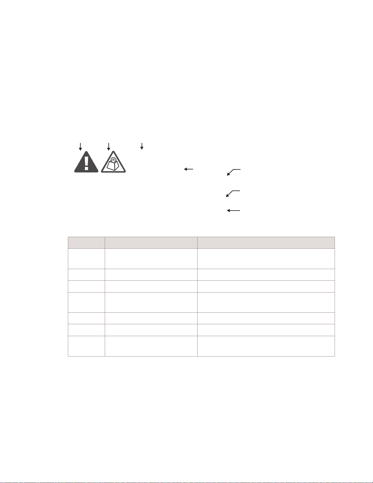
General structure
Safety statements include the following structural elements:
BC D
CAUTION
Lifting hazard
Lifting this equipment by yourself can result in injury
due to the size and weight of the equipment.
Always use three people or a lifting device to transport
and position this equipment. [ABC123]
SAMPLE
Item Structure element Purpose
1 Safety alert symbol Indicates the potential for personal injury
2 Safety symbol Indicates hazard type (optional)
3 Signal word Indicates the severity of the hazard
4 Hazard type Describes the source of the risk of damage or
5 Safety message Consequences if protective measures fail
6 Avoidance message Protective measures to take to avoid the hazard
7 Identifier The reference ID of the safety statement
E
(optional)
injury
(optional)
F
G
H
....................................................................................................................................................................................................................................
1-2
Alcatel-Lucent – Proprietary
Use pursuant to applicable agreements
9927 Dist BTS Outdoor
401-703-516
Issue 1 March 2012
Page 11

Safety Structure of safety statements
....................................................................................................................................................................................................................................
Signal words
The signal words identify the hazard severity levels as follows:
Signal word Meaning
DANGER Indicates an extremely hazardous situation which, if not avoided, will
result in death or serious injury.
WARNING Indicates a hazardous situation which, if not avoided, could result in
death or serious injury.
CAUTION Indicates a hazardous situation which, if not avoided, could result in
minor or moderate injury.
NOTICE Indicates a hazardous situation not related to personal injury.
Within this IP, the safety label typically includes additional information such as the hazard
type, a description of the damage that can be caused, and the steps that should be taken to
avoid the hazard.
....................................................................................................................................................................................................................................
9927 Dist BTS Outdoor
401-703-516
Issue 1 March 2012
Alcatel-Lucent – Proprietary
Use pursuant to applicable agreements
1-3
Page 12

Safety Structure of safety statements
....................................................................................................................................................................................................................................
WARNING
Personal Injury or Damage to Equipment
Failure to observe these safety precautions may result in personal injury or damage to
equipment.
• Read and understand all instructions.
• Follow all warnings and instructions marked on this product.
• Installation and maintenance procedures must be followed and performed by trained
personnel only.
• Grounding and circuit continuity is vital for safe operation of the equipment. Never
operate the equipment with grounding/bonding conductor disconnected.
• Install only equipment identified in the product's installation manual. Use of other
equipment may result in an improper connection which could lead to fire or injury.
• Use caution when installing or modifying telecommunications lines.
• The product has multiple power inputs. Before servicing, Disconnect all inputs to
reduce the risk of energy hazards.
• For continued protection against risk of fire, all fuses used in this product must be
replaced only with fuses of the same type and rating.
• Never install telecommunications wiring during a lightning storm.
• Never install telecommunications connections in wet locations.
• Never touch uninsulated telecommunications wiring or terminals unless the
telecommunications line has been disconnected at the interface.
• Never push objects of any kind into the product through slots, as they may touch
dangerous voltage points or short-out parts that could result in a fire or an electrical
short.
• Never spill liquids of any kind on the product.
• Slots and openings in the product are provided for ventilation. To protect it from
overheating, these openings must not be blocked or covered. The product should not
be placed in a built-in installation unless proper ventilation is provided.
• To reduce the risk of an electrical shock, do not disassemble the product. Opening and
removing covers and/or circuit boards may expose you to dangerous voltages or other
risks. Incorrect reassembly can cause electrical shock when the unit is subsequently
used.
....................................................................................................................................................................................................................................
1-4
Alcatel-Lucent – Proprietary
Use pursuant to applicable agreements
9927 Dist BTS Outdoor
401-703-516
Issue 1 March 2012
Page 13

Safety Safety - specific hazards
....................................................................................................................................................................................................................................
Safety - specific hazards
DANGER
Lightning Strikes!
Lightning strikes are possible during stormy weather and could result in death or severe
injury.
Do not work on the installation itself or on the power supply lines or antenna feeders of a
9927 during stormy weather.
WARNING
Energy Hazard!
Some parts of all electrical installations are energized. Failure to observe this fact and
the safety warnings may lead to bodily injury and property damage.
For this reason, only trained and qualified personnel may install or service the
installation.
WARNING
Energy Hazard!
The power supply lines to the network element are energized. Short circuits can cause
burns to the face and hands.
Open the load disconnect switch in the distribution box to completely de-energize the
network element.
....................................................................................................................................................................................................................................
9927 Dist BTS Outdoor
401-703-516
Issue 1 March 2012
Alcatel-Lucent – Proprietary
Use pursuant to applicable agreements
1-5
Page 14

Safety Safety - specific hazards
....................................................................................................................................................................................................................................
WARNING
Beryllium Oxide Poisoning Hazard!
The transmitter units include components which contain beryllium oxide (BeO). In this
form, BeO ceramics do not constitute a hazardous material as long as this material is not
destroyed by external mechanical forces.
In the event that repair work is carried out by the customer or by third parties, the
following regulations must be observed:
• Applicable version of the Regulation on Hazardous Materials in the Workplace
• Appropriate accident prevention regulations
The following must be specifically observed:
• Eating, drinking, and smoking are not permitted in workplaces where BeO ceramic
components are being worked on.
• Wash your hands carefully under running water after working with BeO ceramic
components.
If the following symptoms occur, contact a physician:
• Irritation of the respiratory organs
• Difficulty breathing or skin irritation
NOTICE
Condensation may cause a short circuit!
Sudden changes in the weather may lead to the formation of condensation on
components. Operating the unit when condensation moisture is present can destroy the
unit.
Units which show signs of condensation must be dried before installation.
....................................................................................................................................................................................................................................
1-6
Alcatel-Lucent – Proprietary
Use pursuant to applicable agreements
9927 Dist BTS Outdoor
401-703-516
Issue 1 March 2012
Page 15

Safety Safety - specific hazards
....................................................................................................................................................................................................................................
NOTICE
ESD hazard
Semiconductor elements can be damaged by static discharges.
The following rules must be complied with when handling any module containing
semiconductor components:
• Wear conductive or antistatic work clothes (for example, coat made of 100% cotton).
• Wear grounded ESD wrist strap.
• Wear shoes with conductive soles.
• Leave the modules in their original packaging until ready for use.
• Make sure there is no difference in potential between yourself, the workplace, and the
package before removing, unpacking, or packing a module.
• Hold the module only by the grip without touching the connection pins, tracks, or
components.
• Place modules removed from the equipment on a conductive surface.
• Test or handle the module only with grounded tools on grounded equipment.
• Handle defective modules exactly like new ones to avoid causing further damage.
DANGER
Cabinet lifting hazard!
When lifting cabinets, incorrect or improperly installed eyebolts will fail endangering
personnel to bodily injury and destroying the equipment.
Avoid using the wrong eyebolts by following these guideline:
• If a ½- inch eyebolt threads easily and fully into a lifting nut on the top of the cabinet,
then use the ½- inch eyebolts.
• If not, check the threads for 12 mm eyebolts. The 12 mm eyebolt should thread all the
way down without binding, until it bottoms out.
• A 12-mm eyebolt is too small for a ½-inch lifting nut, but will not hand thread all the
way into the ½-inch nut unless forced. It will cross thread if forced, and may pull out
when hoisting, presenting a serious danger. Do NOT force 12-mm eyebolts into
½-inch lifting nuts. Doing so will damage the threads of the lifting nuts.
• A ½-inch eyebolt will thread less than half a thread into a 12-mm lifting nut. Do NOT
force ½-inch eyebolts into 12-mm lifting nuts. Doing so will damage the threads of
the lifting nuts.
....................................................................................................................................................................................................................................
9927 Dist BTS Outdoor
401-703-516
Issue 1 March 2012
Alcatel-Lucent – Proprietary
Use pursuant to applicable agreements
1-7
Page 16

Safety Product safety
....................................................................................................................................................................................................................................
Product safety
Conformance statements
See Appendix G, “Product conformance statements” for all conformance statements that
apply to this product.
Equipment safety
Safety information for this equipment can be found on various Caution, Warning, Danger,
information labels or instructions affixed to or included with the cabinet, its internal
assemblies or included within this document. Informational and cautionary labels may
appear near the item they address or may be grouped in a single location on the
equipment. Warnings are typically adjacent to the hazard that is noted on the label. The
instructions, cautions and warnings found on these labels must be understood and
observed by all personnel involved with the equipment installation and maintenance.
Important! Refer to “Structure of safety statements” (p. 1-2) for definitions of safety
labels.
Equipment safety for 1900 MHz, 4x45W (65 MHz) RRH
The message below applies to the 1900 MHz, 4x45W (65 MHz) RRH.
Important! These units are intended for installation only in restricted access areas,
where access can only be gained by trained service personnel and through the use of a
tool, lock and key or other means of security, and where access is controlled by the
authority responsible for the location
....................................................................................................................................................................................................................................
1-8
Alcatel-Lucent – Proprietary
Use pursuant to applicable agreements
9927 Dist BTS Outdoor
401-703-516
Issue 1 March 2012
Page 17

2 2Product overview for 9927
Distributed Base Station
Outdoor cabinet
Overview
Purpose
This chapter provides an overview of the 9927 Distributed Base Station Outdoor Cabinet.
Contents
Network view 2-2
Configurations 2-3
Product overview 2-4
Physical description 2-6
Components inside cabinet 2-13
Weights and dimensions of equipment 2-14
60ECv2 battery cabinet overview 2-19
...................................................................................................................................................................................................................................
9927 Dist BTS Outdoor
401-703-516
Issue 1 March 2012
Alcatel-Lucent – Proprietary
Use pursuant to applicable agreements
2-1
Page 18

Product overview for 9927 Distributed Base Station
Outdoor cabinet
....................................................................................................................................................................................................................................
Network view
Network view
Overview
The 9927 Distributed Base Station is a Multi-Technology, Multi-Band BTS that supports
multiple access technologies. The RRHs are multi-functional and support both CDMA
and LTE.
For CDMA, the MT-BBU interfaces with the RRHs via optical link.
The 1900 MHz (PCS) RRH operates in BC1 band and supports both LTE and CDMA.
The 800 MHz RRH operates in BC10 band and supports CDMA only.
The LTE RRH is hardware ready to support PCS in the G-Block.
LTE in the BC10 band is not supported in initial deployment.
Backhaul to the network is provided via the SAR-7705, either as:
• Fiber optic cable
• Microwave cable
• T1/E1 line
• OC3
• DS3
The -48 VDC power source inside the cabinet provides -48 VDC to the components
inside the cabinet and to the RRHs.
Signal flow block diagram
The high-level signal flow diagram below shows how signals flow within the
Alcatel-Lucent 9927 Distributed Base Station outdoor cabinet and to the RRHs and
Backhaul Network. (4G Backhaul is assumed to be available at the cell site.)
....................................................................................................................................................................................................................................
2-2
Alcatel-Lucent – Proprietary
Use pursuant to applicable agreements
9927 Dist BTS Outdoor
401-703-516
Issue 1 March 2012
Page 19

Product overview for 9927 Distributed Base Station
Outdoor cabinet
....................................................................................................................................................................................................................................
Configurations
Configurations
Configurations
In FID 15364.0, the 9927 Distributed BTS supports the following configurations:
• Up to 4 carriers/3 sectors PCS (1x-A and EVDO) with 4-BR, if PCS RRH is shared
with LTE [5 MHz on G block (band class 25)].
• Up to 1 carrier/3 sectors BC10 (1x-A) 2- BR .
If a higher CDMA carrier count is needed, a second PCS RRH may be required.
The 9927 Distributed BTS supports the following configurations:
• One MT-BBU, 8 Carriers/3 Sectors (4 Carriers 1x/1x Advance and 4 Carriers EVDO)
— 3 BC1, 4x40W RRH with 4 branch Rx
— 3 BC10, 2x50W RRH with 2 branch Rx
— No daisy chaining
• One MT-BBU and one LTE BBU, 10 Carriers/3 Sectors (4 Carriers 1x/1x Advance
and 4 Carriers EVDO)
— 3 BC1, 4x40W LTE RRH with 4 branch Rx
— 3 BC10, 2x50W RRH with 2 branch Rx
— Daisy chaining
....................................................................................................................................................................................................................................
9927 Dist BTS Outdoor
401-703-516
Issue 1 March 2012
Alcatel-Lucent – Proprietary
Use pursuant to applicable agreements
2-3
Page 20

Product overview for 9927 Distributed Base Station
Outdoor cabinet
....................................................................................................................................................................................................................................
Product overview
Product overview
Introduction
This document supports the following product:
• Alcatel-Lucent 9927 Distributed Base Station outdoor cabinet
Product description for Alcatel-Lucent 9927 Distributed Base Station
The Alcatel-Lucent 9927 Distributed Base Station is a multi-modal baseband cabinet,
configured with Remote Radio Heads (RRHs), which provides:
• CDMA in the PCS band (Bandclass 1 or 14) and 800 MHz band (Bandclass 10)
• Optional LTE in the PCS band (typically Block G). Resources are shared with
CDMA.
The signal flow diagram below shows how CDMA, 1xEV-DO, and LTE signals are
routed from the baseband cabinet to the RRHs. One sector is shown.
CDMA is processed by the Digital Shelf, which uses 9927 common platform architecture.
Backhaul to the Network is accomplished with T1/E1 lines, fiber optic cable, or
microwave.
The RRHs that are used are as follows:
• 1900 MHz, 4x40W (25 MHz)
• 1900 MHz, 4x45W (65 MHz)
• 800 MHz, 2x50W
The cabinet is equipped with a top solar shield. See Chapter 4, “Site configurations for
9927 Distributed
Requirements
BTS Outdoor Cabinet” for line-up configurations.
The following table lists the requirements for the 9927 Distributed Base Station Outdoor
Cabinet.
Requirements Values
Frequency Bands • 3GPP2 Band Class 1 (1900 MHz – United States PCS frequency
band spectrum). Blocks A,B,C,D,E,F. [FID 15597.0]
• 3GPP2 Band Class 10 [FID 15599.0]
• PCS – G Block (band class 25) used only for LTE.
Operating Temperature • -40 °C to +46 °C (-40 °F to +115 °F) standard
• -40 °C to 50 °C (-40 °F to 122 °F) extended
....................................................................................................................................................................................................................................
2-4
Alcatel-Lucent – Proprietary
Use pursuant to applicable agreements
9927 Dist BTS Outdoor
401-703-516
Issue 1 March 2012
Page 21

Product overview for 9927 Distributed Base Station
Outdoor cabinet
....................................................................................................................................................................................................................................
Product overview
Requirements Values
Power
Battery backup
Operating Voltage
Sectors
T1/E1 Facilities
User Alarms
GPS Antenna
Integrated Power
Up to two 60ECv2 battery cabinets
-48 VDC
3,sector
Up to 16 T1/E1s (optional)
32 for external User Alarms
Yes
....................................................................................................................................................................................................................................
9927 Dist BTS Outdoor
401-703-516
Issue 1 March 2012
Alcatel-Lucent – Proprietary
Use pursuant to applicable agreements
2-5
Page 22

Product overview for 9927 Distributed Base Station
Outdoor cabinet
....................................................................................................................................................................................................................................
Physical description
Physical description
Diagram
The figure below shows the 9927 Distributed BTS outdoor cabinet with the front door
closed.
....................................................................................................................................................................................................................................
2-6
Alcatel-Lucent – Proprietary
Use pursuant to applicable agreements
9927 Dist BTS Outdoor
401-703-516
Issue 1 March 2012
Page 23

Product overview for 9927 Distributed Base Station
Physical description
Outdoor cabinet
....................................................................................................................................................................................................................................
....................................................................................................................................................................................................................................
9927 Dist BTS Outdoor
401-703-516
Issue 1 March 2012
Alcatel-Lucent – Proprietary
Use pursuant to applicable agreements
2-7
Page 24

Product overview for 9927 Distributed Base Station
Physical description
Outdoor cabinet
....................................................................................................................................................................................................................................
The figure below illustrates the position of each component inside the 9927 Distributed
BTS cabinet.
....................................................................................................................................................................................................................................
2-8
Alcatel-Lucent – Proprietary
Use pursuant to applicable agreements
9927 Dist BTS Outdoor
401-703-516
Issue 1 March 2012
Page 25

Product overview for 9927 Distributed Base Station
Physical description
Outdoor cabinet
....................................................................................................................................................................................................................................
The following figure is a left-side view of the 9927 Distributed Base Station Outdoor
Cabinet. The dimensions are shown in mm and inches.
....................................................................................................................................................................................................................................
9927 Dist BTS Outdoor
401-703-516
Issue 1 March 2012
Alcatel-Lucent – Proprietary
Use pursuant to applicable agreements
2-9
Page 26

Product overview for 9927 Distributed Base Station
Physical description
Outdoor cabinet
....................................................................................................................................................................................................................................
The following figure is a front view of the 9927 Distributed Base Station Outdoor
Cabinet. The dimensions are shown in mm and inches.
....................................................................................................................................................................................................................................
2-10
Alcatel-Lucent – Proprietary
Use pursuant to applicable agreements
9927 Dist BTS Outdoor
401-703-516
Issue 1 March 2012
Page 27

Product overview for 9927 Distributed Base Station
Outdoor cabinet
....................................................................................................................................................................................................................................
Physical description
The following figure is a right-side view of the 9927 Distributed Base Station Outdoor
Cabinet. The dimensions are shown in mm and inches.
Description
This 9927 Distributed Base Station Outdoor Cabinet features Fresh Air Cooling (FAC).
The FAC uses filter membrane technology to achieve clean-room conditions inside the
baseband cabinet.
....................................................................................................................................................................................................................................
9927 Dist BTS Outdoor
401-703-516
Issue 1 March 2012
Alcatel-Lucent – Proprietary
Use pursuant to applicable agreements
2-11
Page 28

Product overview for 9927 Distributed Base Station
Outdoor cabinet
....................................................................................................................................................................................................................................
Physical description
The 9927 Distributed Base Station Outdoor Cabinet is equipped with the following
features:
• Filter Life Alarm - The cabinet has a pressure sensing alarm that sends an alarm when
more than the normal amount of suction is needed to draw air into the baseband
cabinet.
The interior of the baseband cabinet is held at negative pressure (lower than ambient air
pressure). All openings on the cabinet must be sealed to maintain negative pressure inside
the baseband cabinet when the baseband cabinet is in operation.
Important! Refer to Appendix D, “Guidelines for lifting and moving cabinets ” for
guidelines
regarding
lifting and moving of the cabinet.
....................................................................................................................................................................................................................................
2-12
Alcatel-Lucent – Proprietary
Use pursuant to applicable agreements
9927 Dist BTS Outdoor
401-703-516
Issue 1 March 2012
Page 29

Product overview for 9927 Distributed Base Station
Outdoor cabinet
....................................................................................................................................................................................................................................
Components inside cabinet
Components inside cabinet
Purpose
This section lists the components that can be populated in the 9927 Distributed Base
Station Outdoor Cabinet.
9927 Distributed Base Station Outdoor Cabinet components
The table below lists the components inside the 9927 Distributed Base Station Outdoor
Cabinet.
Components inside 9927 Distributed Base Station Outdoor Cabinet
The 9927 Distributed Base Station Outdoor Cabinet can contain the following modules:
• SAR 7705 SAR-8 (expandable) or 7705 SAR-F (fixed). 7705 SAR-M (future).
• Two 7210 SAS M (-48 VDC) -- only for microwave backhaul
• LTE TDD, 2.6 GHz (Optional) or
• CDMA MT-BBU
• CDMA MT-BBU Growth
• One or two -48 VDC PDPs -- second unit is optional. Needed only for cabinet is upgrade.
• 4-Position SEC-B Tray (ETSI) -- used only with T1/E1 Backhaul. T1/E1 Backhaul is via the SAR.
• Thermal Switch for Power Injectors
• Microwave Power Injector (PIB), -48 VDC
• ACPDA
• GFCI Convenience Outlet
• Heater Assembly
• User Alarm interface
• Alarms
....................................................................................................................................................................................................................................
9927 Dist BTS Outdoor
401-703-516
Issue 1 March 2012
Alcatel-Lucent – Proprietary
Use pursuant to applicable agreements
2-13
Page 30

Product overview for 9927 Distributed Base Station
Outdoor cabinet
....................................................................................................................................................................................................................................
Weights and dimensions of equipment
Weights and dimensions of equipment
Introduction
This section provides physical specifications for one configuration of the 9927
Distributed Base Station Outdoor Cabinet.
The weights and dimensions, listed in the table below, include the top solar shield.
9927 Distributed Base Station Outdoor Cabinet weights and dimensions
The table below lists the weights and dimensions for a half-loaded and fully-loaded 9927
Distributed Base Station Outdoor Cabinet.
Cabinets Configuration Shipped Weight
9927 Distributed Base
Station Outdoor
Cabinet with Integrated
Power
Half loaded
• CDMA
• One BBU
• One 7210
• One SAR 8
• Three DC-DC convertors
Fully loaded
• CDMA
• Four BBUs
• Two 7210s
• One SAR 8
• Six DC-DC convertors
• 8 Injectors
including pallet
(estimate)
470 kg
(1033 lbs)
529 kg
(1162 lbs)
60ECv2 battery cabinet weights and dimensions
The table below provides the weights and dimensions of the 60ECv2 battery cabinet.
Maximum
Installed Weight
(estimate)
430 kg
(945 lbs)
489 kg
(1074 lbs)
Reference Dimensions
(Width x Depth x Height)
900 mm x 960 mm x 1925
mm
(35.4 inches x 37.8 inches x
75.8 inches)
Cabinets Configuration Shipped Weight
60ECv2 Battery System 60ECv2 battery cabinet
equipped with 20 12IR145
batteries
....................................................................................................................................................................................................................................
2-14
Alcatel-Lucent – Proprietary
Use pursuant to applicable agreements
including pallet
(estimate)
195 (430) 1284 (2830) 760x790x1500 (30 x 31 x
Maximum
Installed Weight
(estimate)
Reference Dimensions
(Width x Depth x Height)
60)
9927 Dist BTS Outdoor
401-703-516
Issue 1 March 2012
Page 31

Product overview for 9927 Distributed Base Station
Outdoor cabinet
....................................................................................................................................................................................................................................
Weights and dimensions of equipment
Component weights
The following table provides approximate weights for batteries and other miscellaneous
hardware.
Item Weight
12IR145 battery
KS24734 Rectifier
Pallet
45 kg (100 lbs)
6 kg (14 lbs)
40 kg (88 lbs)
....................................................................................................................................................................................................................................
9927 Dist BTS Outdoor
401-703-516
Issue 1 March 2012
Alcatel-Lucent – Proprietary
Use pursuant to applicable agreements
2-15
Page 32

Product overview for 9927 Distributed Base Station
Outdoor cabinet
....................................................................................................................................................................................................................................
Weights and dimensions of equipment
9927 Distributed Base Station Outdoor Cabinet dimensions
The following figure is a left-side view of the 9927 Distributed Base Station Outdoor
Cabinet. The dimensions are shown in mm and inches.
....................................................................................................................................................................................................................................
2-16
Alcatel-Lucent – Proprietary
Use pursuant to applicable agreements
9927 Dist BTS Outdoor
401-703-516
Issue 1 March 2012
Page 33

Product overview for 9927 Distributed Base Station
Weights and dimensions of equipment
Outdoor cabinet
....................................................................................................................................................................................................................................
The following figure is a front view of the 9927 Distributed Base Station Outdoor
Cabinet. The dimensions are shown in mm and inches.
....................................................................................................................................................................................................................................
9927 Dist BTS Outdoor
401-703-516
Issue 1 March 2012
Alcatel-Lucent – Proprietary
Use pursuant to applicable agreements
2-17
Page 34

Product overview for 9927 Distributed Base Station
Weights and dimensions of equipment
Outdoor cabinet
....................................................................................................................................................................................................................................
The following figure is a right-side view of the 9927 Distributed Base Station Outdoor
Cabinet. The dimensions are shown in mm and inches.
....................................................................................................................................................................................................................................
2-18
Alcatel-Lucent – Proprietary
Use pursuant to applicable agreements
9927 Dist BTS Outdoor
401-703-516
Issue 1 March 2012
Page 35

Product overview for 9927 Distributed Base Station
60ECv2 battery cabinet overview
Outdoor cabinet
....................................................................................................................................................................................................................................
60ECv2 battery cabinet overview
60ECv2 description
This topic provides a description of the 60ECv2 battery cabinet.
The optional 60ECv2 battery cabinet provides battery backup for the 9927 Distributed
Base Station Outdoor Cabinet. The 60ECv2 battery cabinet can contain up to (20)
12IR-145 batteries. Up to two 60ECv2 battery cabinets can be installed to the right of the
9927 Distributed Base Station Outdoor Cabinet.
Hole for
Padlock
(Top View)
Front
View
Lock
Lock
Unlock
(4 Places)
Unlock
(2 Places)
Hole for
Padlock
(Top View)
Rear
View
2
25 mm # 2 AWG( ) Ground/Earth Lug
to Ground/Earth Bar (2 Places)
....................................................................................................................................................................................................................................
9927 Dist BTS Outdoor
401-703-516
Issue 1 March 2012
Alcatel-Lucent – Proprietary
Use pursuant to applicable agreements
2-19
Page 36

Product overview for 9927 Distributed Base Station
60ECv2 battery cabinet overview
Outdoor cabinet
....................................................................................................................................................................................................................................
....................................................................................................................................................................................................................................
2-20
Alcatel-Lucent – Proprietary
Use pursuant to applicable agreements
9927 Dist BTS Outdoor
401-703-516
Issue 1 March 2012
Page 37

3 3Product overview for RRHs
Overview
Purpose
This chapter provides an overview of the Alcatel-Lucent Remote Radio Head, with
optional power and battery back up.
Contents
Typical RRH/antenna array 3-2
External views of RRHs 3-3
Detailed physical description 3-6
Functional description of RRHs 3-18
Antenna Remote Electronic Tilt (RET) — FID 13019.36 3-19
RRH mounting configurations 3-20
RRHs and related equipment 3-23
...................................................................................................................................................................................................................................
9927 Dist BTS Outdoor
401-703-516
Issue 1 March 2012
Alcatel-Lucent – Proprietary
Use pursuant to applicable agreements
3-1
Page 38

Product overview for RRHs Typical RRH/antenna array
....................................................................................................................................................................................................................................
Typical RRH/antenna array
Typical RRH/antenna arrays on tower
The figure below shows a typical RRH/antenna array on a tower.
....................................................................................................................................................................................................................................
3-2
Alcatel-Lucent – Proprietary
Use pursuant to applicable agreements
9927 Dist BTS Outdoor
401-703-516
Issue 1 March 2012
Page 39

Product overview for RRHs External views of RRHs
....................................................................................................................................................................................................................................
External views of RRHs
Orthogonal view of 1900 MHz, PCS, 4x40W (25 MHz) RRH
The following figure is an orthogonal view of the 1900 MHz, PCS, 4x40W (25 MHz)
RRH. Dimensions are shown in mm.
330
(13.0)
580
(22.8)
440
(17.3)
....................................................................................................................................................................................................................................
9927 Dist BTS Outdoor
401-703-516
Issue 1 March 2012
Alcatel-Lucent – Proprietary
Use pursuant to applicable agreements
3-3
Page 40

Product overview for RRHs External views of RRHs
....................................................................................................................................................................................................................................
Orthogonal view of 1900 MHz, PCS, 4x45W (65 MHz) RRH
The following figure is an orthogonal view of the 1900 MHz, PCS, 4x45W (65 MHz)
RRH. Dimensions are shown in mm.
272
637
282
Orthogonal view of 800 MHz, 2x50W RRH (OEM1)
The following figure is an orthogonal view of the OEM1, 800 MHz, 2x50W RRH.
Dimensions are shown in mm.
500
800 Mhz
(23 kg/50.6 lbs)
385
330
....................................................................................................................................................................................................................................
3-4
Alcatel-Lucent – Proprietary
Use pursuant to applicable agreements
9927 Dist BTS Outdoor
401-703-516
Issue 1 March 2012
Page 41

Product overview for RRHs External views of RRHs
....................................................................................................................................................................................................................................
Orthogonal view of 800 MHz, 2x50W RRH (OEM2)
The following figure is an orthogonal view of the OEM2, 800 MHz, 2x50W RRH.
Dimensions are shown in mm.
330
400
255
800 Mhz
(23 kg/50.6 lbs)
....................................................................................................................................................................................................................................
9927 Dist BTS Outdoor
401-703-516
Issue 1 March 2012
Alcatel-Lucent – Proprietary
Use pursuant to applicable agreements
3-5
Page 42

Product overview for RRHs Detailed physical description
....................................................................................................................................................................................................................................
Detailed physical description
Identify RRHs according to front, top and bottom views
Use the table below to identify each RRH using the front, top and bottom views.
Front, top and bottom views of RRHs-- for identification
Frequency Front View Top View Bottom View
1900 MHz PCS Refer to “Front view of 1900
MHz, PCS, 4x40W (25 MHz)
RRH” (p. 3-7)
1900 MHz PCS
,
4X45W
65
MHz
OEM1, 800
2x50W
MHz,
Refer to “Front view of 1900
MHz, PCS, 4x45W (65 MHz)
RRH” (p. 3-10)
Refer
to “Front view of
OEM1, 800 MHz, 2x50W
RRH” (p. 3-13)
Refer
OEM2, 800
2x50W
MHz,
to “Front view of
OEM2, 800 MHz, 2x50W
RRH” (p. 3-14)
Refer to “Top view of 1900
PCS, 4x40W (25
MHz,
MHz) RRH ” (p. 3-8)
Refer to“Top view of 1900
PCS, 4x45W (65
MHz,
MHz) RRH ” (p. 3-11)
Refer to “Top view of
OEM1,
800 MHz, 2x50W
RRH” (p. 3-13)
Refer to “Top view of
OEM2,
800 MHz, 2x50W
RRH” (p. 3-15)
Refer to “Bottom view of
MHz, PCS, 4x40W
1900
(25 MHz) RRH ” (p. 3-9)
Refer to“Bottom view of
MHz, PCS, 4x45W
1900
(65 MHz) RRH ” (p. 3-12)
Refer to “Bottom view of
OEM1,
800 MHz, 2x50W
RRH” (p. 3-14)
Refer to “Bottom view of
OEM2,
800 MHz, 2x50W
RRH” (p. 3-15)
....................................................................................................................................................................................................................................
3-6
Alcatel-Lucent – Proprietary
Use pursuant to applicable agreements
9927 Dist BTS Outdoor
401-703-516
Issue 1 March 2012
Page 43

Product overview for RRHs Detailed physical description
....................................................................................................................................................................................................................................
Front view of 1900 MHz, PCS, 4x40W (25 MHz) RRH
The following figure is a front view of the 1900 MHz PCS, 4x40W (25 MHz) RRH.
....................................................................................................................................................................................................................................
9927 Dist BTS Outdoor
401-703-516
Issue 1 March 2012
Alcatel-Lucent – Proprietary
Use pursuant to applicable agreements
3-7
Page 44

Product overview for RRHs Detailed physical description
....................................................................................................................................................................................................................................
Top view of 1900 MHz, PCS, 4x40W (25 MHz) RRH
The following figure is a top view of the 1900 MHz PCS, 4x40W (25 MHz) RRH.
....................................................................................................................................................................................................................................
3-8
Alcatel-Lucent – Proprietary
Use pursuant to applicable agreements
9927 Dist BTS Outdoor
401-703-516
Issue 1 March 2012
Page 45

Product overview for RRHs Detailed physical description
....................................................................................................................................................................................................................................
Bottom view of 1900 MHz, PCS, 4x40W (25 MHz) RRH
The following figure shows the connectors on the bottom of the 1900 MHz, PCS, 4x40W
(25 MHz) RRH.
Tx2 MON
ALM
Tx2 MON
AUX Rx2
AUX Rx1
CPRI PRI
CPRI SEC
ASIG
....................................................................................................................................................................................................................................
9927 Dist BTS Outdoor
401-703-516
Issue 1 March 2012
Alcatel-Lucent – Proprietary
Use pursuant to applicable agreements
3-9
Page 46

Product overview for RRHs Detailed physical description
....................................................................................................................................................................................................................................
Front view of 1900 MHz, PCS, 4x45W (65 MHz) RRH
The following figure is a front view of the 1900 MHz, PCS, 4x45W (65 MHz) RRH.
....................................................................................................................................................................................................................................
3-10
Alcatel-Lucent – Proprietary
Use pursuant to applicable agreements
9927 Dist BTS Outdoor
401-703-516
Issue 1 March 2012
Page 47

Product overview for RRHs Detailed physical description
....................................................................................................................................................................................................................................
Top view of 1900 MHz, PCS, 4x45W (65 MHz) RRH
The following figure is a top view of the 1900 MHz, PCS, 4x45W (65 MHz) RRH.
....................................................................................................................................................................................................................................
9927 Dist BTS Outdoor
401-703-516
Issue 1 March 2012
Alcatel-Lucent – Proprietary
Use pursuant to applicable agreements
3-11
Page 48

Product overview for RRHs Detailed physical description
....................................................................................................................................................................................................................................
Bottom view of 1900 MHz, PCS, 4x45W (65 MHz) RRH
The following figure shows the connectors on the bottom of the 1900 MHz, PCS, 4x45W
(65 MHz) RRH.
....................................................................................................................................................................................................................................
3-12
Alcatel-Lucent – Proprietary
Use pursuant to applicable agreements
9927 Dist BTS Outdoor
401-703-516
Issue 1 March 2012
Page 49

Product overview for RRHs Detailed physical description
....................................................................................................................................................................................................................................
Front view of OEM1, 800 MHz, 2x50W RRH
The following figure is a front view of the OEM1, 800 MHz, 2x50W RRH.
Top view of OEM1, 800 MHz, 2x50W RRH
The following figure is a top view of the OEM1, 800 MHz, 2x50W RRH.
....................................................................................................................................................................................................................................
9927 Dist BTS Outdoor
401-703-516
Issue 1 March 2012
Alcatel-Lucent – Proprietary
Use pursuant to applicable agreements
3-13
Page 50

Product overview for RRHs Detailed physical description
....................................................................................................................................................................................................................................
Bottom view of OEM1, 800 MHz, 2x50W RRH
The following figure is a bottom view of the OEM1, 800 MHz, 2x50W RRH.
Front view of OEM2, 800 MHz, 2x50W RRH
The following figure is a front view of the OEM2, 800 MHz, 2x50W RRH.
....................................................................................................................................................................................................................................
3-14
Alcatel-Lucent – Proprietary
Use pursuant to applicable agreements
9927 Dist BTS Outdoor
401-703-516
Issue 1 March 2012
Page 51

Product overview for RRHs Detailed physical description
....................................................................................................................................................................................................................................
Top view of OEM2, 800 MHz, 2x50W RRH
The following figure is a top view of the OEM2, 800 MHz, 2x50W RRH.
Bottom view of OEM2, 800 MHz, 2x50W RRH
The following figure shows the connectors on the bottom of the OEM2, 800 MHz,
2x50W RRH.
AUX Rx1
Bottom view of 1900 MHz, 4x40W (65 MHz) RRH
AUX RX2
Tx1 MON
CPRI PRI
Tx2 MON
CPRI PRI
ALM
ALD
STATUS
-48VIN
Get figs from attachment!
....................................................................................................................................................................................................................................
9927 Dist BTS Outdoor
401-703-516
Issue 1 March 2012
Alcatel-Lucent – Proprietary
Use pursuant to applicable agreements
3-15
Page 52

Product overview for RRHs Detailed physical description
....................................................................................................................................................................................................................................
Connectors on 1900 MHz RRH
The following table lists the connectors on the 1900 MHz RRH and the function of each
connector.
Connectors on 1900 MHz RRH
Connector Function
TX1/RX1 (25 MHz — top of RRH/ 65 MHz
Transmit and receive, antenna path 1
— bottom of RRH)
TX2/RX2 (25 MHz — top of RRH/ 65 MHz
Transmit and receive, antenna path 2
— bottom of RRH)
TX3/RX3 (25 MHz — top of RRH/ 65 MHz
Transmit and receive, antenna path 3
— bottom of RRH)
TX4/RX4 (25 MHz — top of RRH/ 65 MHz
Transmit and receive, antenna path 4
— bottom of RRH)
Grounding Points (on left and right side of 25
MHz RRH)RRH grounding points [Left and
25 MHz / Bottom for 65 MHz]
for
Right
Connect 6 AWG (outdoor) or 2 AWG (indoor)
ground wire terminated with 2–hole lug to
RRH.
AUX RX1 Antenna-sharing port
AUX RX2 N/A
CPRI PRI CPRI optical main port
CPRI SEC CPRI optical daisy-chained port
AISG Remote Electronic Tilt (RET)
ALM 2 x 8 pin circular
TX1 MON
TX2 MON
-48 V
RRH connectors on OEM2 RRH
The following table lists the connectors on the OEM2 RRH and the function of each
connector.
Connectors on OEM2 RRH
Connector Function
TX/RX1 (at top of RRH) Transmit and receive, antenna path 1
TX/RX2 (at top of RRH) Transmit and receive, antenna path 2
....................................................................................................................................................................................................................................
3-16
Alcatel-Lucent – Proprietary
Use pursuant to applicable agreements
9927 Dist BTS Outdoor
401-703-516
Issue 1 March 2012
Page 53

Product overview for RRHs Detailed physical description
....................................................................................................................................................................................................................................
Connector Function
Grounding Points (on left and right sides of
Grounding point
RRHs)RRH grounding points
AUX RX1 Antenna-sharing
port
AUX RX2 Antenna-sharing port
CPRI PRI CPRI optical main port
CPRI SEC CPRI optical daisy-chained port
STATUS
ALM 2 x 8 pin circular
TX1 MON
TX2 MON
ALD
-48 V IN –48 VDC input power
....................................................................................................................................................................................................................................
9927 Dist BTS Outdoor
401-703-516
Issue 1 March 2012
Alcatel-Lucent – Proprietary
Use pursuant to applicable agreements
3-17
Page 54

Product overview for RRHs Functional description of RRHs
....................................................................................................................................................................................................................................
Functional description of RRHs
General description
The three RRHs pictured below are used with 800 MHz CDMA, PCS CDMA, and LTE
technologies.
Product configurations
The configurations offered in this release are as follows:
• One sector (consists of two 1900 MHz RRHs and one 800 MHz RRH per sector)
Product capabilities
The product capabilities for the RRHs are as follows:
• 1900 MHz
— PCS CDMA
—LTE
— Outdoor, -48 VDC
• 800 MHz
— CDMA
— Outdoor, -48 VDC
....................................................................................................................................................................................................................................
3-18
Alcatel-Lucent – Proprietary
Use pursuant to applicable agreements
9927 Dist BTS Outdoor
401-703-516
Issue 1 March 2012
Page 55

Product overview for RRHs Antenna Remote Electronic Tilt (RET) — FID 13019.36
....................................................................................................................................................................................................................................
Antenna Remote Electronic Tilt (RET) — FID 13019.36
General description
FID-13019.36 introduces a Remote Radio Head (RRH) with an associated RET/ALD
controller that operates the RET.
The RET consists of an actuator motor with supporting control electronics. The RET
adjusts the antenna down-tilt angle by electrically changing the antenna phase angle. By
altering the phase of the antenna signal, the RET also tilts the antenna beam.. This results
in decreased main, side and backward lobes. This overcomes the shortcomings of
mechanical tilt antennas, where the whole antenna is physically tilted. This system moves
the backward lobe in upward direction and distorts the side-lobe patterns.
AISG interface on RRH
The RRHs are equipped with an Antenna Interface Standards Group (AISG) power and
signaling interface connector that supports third party Antenna Remote Electronic Tilt
(RET) equipment. The PCS RRH 4x and 800 MHz RRH 2x are hardware ready to
support the third party RET.
....................................................................................................................................................................................................................................
9927 Dist BTS Outdoor
401-703-516
Issue 1 March 2012
Alcatel-Lucent – Proprietary
Use pursuant to applicable agreements
3-19
Page 56

Product overview for RRHs RRH mounting configurations
....................................................................................................................................................................................................................................
RRH mounting configurations
RRH mounting configurations
The RRHs can be mounted on a:
• Pole
• Wall
• Floor Stand.
Pole mounted RRHs
The following figure shows the 800 MHz/1900 MHz RRH configuration mounted on a
pole. The 800 MHz RRH is mounted directly above the 1900 MHz RRH. Each RRH is
equipped with a lifting handle. The antenna assembly is mounted opposite the RRHs.
Wall mounted RRHs
The following figure shows a typical RRH mounted on a wall with Unitstruts.
....................................................................................................................................................................................................................................
3-20
Alcatel-Lucent – Proprietary
Use pursuant to applicable agreements
9927 Dist BTS Outdoor
401-703-516
Issue 1 March 2012
Page 57

Product overview for RRHs RRH mounting configurations
....................................................................................................................................................................................................................................
Floor Stand mounted RRHs [800 MHz and 4x40W (25 MHz) PCS]
he following figure shows the floor stand that is used with 800 MHz and 4x40W (25
MHz) PCS RRHs. The wall mounting bracket is shown attached.
....................................................................................................................................................................................................................................
9927 Dist BTS Outdoor
401-703-516
Issue 1 March 2012
Alcatel-Lucent – Proprietary
Use pursuant to applicable agreements
3-21
Page 58

Product overview for RRHs RRH mounting configurations
....................................................................................................................................................................................................................................
....................................................................................................................................................................................................................................
3-22
Alcatel-Lucent – Proprietary
Use pursuant to applicable agreements
9927 Dist BTS Outdoor
401-703-516
Issue 1 March 2012
Page 59

Product overview for RRHs RRHs and related equipment
....................................................................................................................................................................................................................................
RRHs and related equipment
Weights and dimensions
This topic covers the weights and dimensions for RRHs and related equipment.
Weights and dimensions of RRHs and accessories
The following table provides weights and dimensions for the RRHs and floor stand.
RRH type or accessory Description Estimated
maximum
installed
Height
mm
(inches)
Width
mm
(inches)
Depth
mm
(inches)
weight
without
mounting
brackets
kg (lbs)
RRH, 800 MHz, OEM1 CDMA/LTE,
23 (50.6) 500 (19.7) 330 (13.0 ) 385 (15.2 )
Dual
RRH, 800 MHz, OEM2 23 (50.6) 400 (15.8) 330 (13.0 ) 255 (10.0 )
Technology, 2
x 50 Watts
RRH, 1900 MHz, 25 MHz
per Tx port
CDMA/LTE,
Dual
Technology, 4
x 40 Watts
47 (104)
[includes 2
RRHs and
mounting
580 (22.8) 330 (13.0 ) 440 (17.3)
brackets]
RRH. 1900 MHz, 65 MHz
per Tx port
CDMA/LTE,
Dual
60 (132) 637 (25.1 ) 282 (11.1 ) 272 (10.7 )
Technology, 4
x 45 Watts
Notch Filter 4 ( 8.8)
Floor Stand n/a 23 (51) 509 (20.1) 360 (14.2) 1226 (48.3)
Miscellaneous hardware weights
The following table provides approximate weights for miscellaneous hardware.
Item Weight kg (lbs)
Pallet ____ (___)
Wall Bracket (RRH) 3.5 (7.7)
Side Support Bracket 3.5 (7.7)
Pole Bracket (Low Profile) 4.3 (9.5)
....................................................................................................................................................................................................................................
9927 Dist BTS Outdoor
401-703-516
Issue 1 March 2012
Alcatel-Lucent – Proprietary
Use pursuant to applicable agreements
3-23
Page 60

Product overview for RRHs RRHs and related equipment
....................................................................................................................................................................................................................................
Item Weight kg (lbs)
Floor Stand (RRH) 23 (50)
Grounding points on RRHs
The grounding points on the 1900 MHz and 800 MHz RRHs are located at the bottom, on
the left and right sides.
....................................................................................................................................................................................................................................
3-24
Alcatel-Lucent – Proprietary
Use pursuant to applicable agreements
9927 Dist BTS Outdoor
401-703-516
Issue 1 March 2012
Page 61

Product overview for RRHs RRHs and related equipment
....................................................................................................................................................................................................................................
The following figure shows how grounding wire is routed to the RRHs.
Ground connection
at top of RRH
(on left side)
Ground connection
at bottom of RRH
(left or right side may
be used)
850 RRH
(Side View)
AWS, PCS RRH
(Front View)
Ground connection
Front sideRear side
Surge protector Surge protector
at top of RRH
(on right side)
Ground connection
at bottom of RRH
(left or right side may
be used)
Ground cable, #6 AWG
The following figures show the grounding points on the OEM2 RRH.
6ft 6ft
Ground cable, #6 AWG
Ground bus bar Ground bus bar
Ground bus barGround bus bar
Note: For antenna sharing 850,AWS, PCS RRHs,
ground connection for surge protector
must be within 6 feet of a ground bus bar.
....................................................................................................................................................................................................................................
9927 Dist BTS Outdoor
401-703-516
Issue 1 March 2012
Alcatel-Lucent – Proprietary
Use pursuant to applicable agreements
3-25
Page 62

Product overview for RRHs RRHs and related equipment
....................................................................................................................................................................................................................................
The left–side grounding point on the OEM2 RRH is located at the left bottom, as shown
in the figure below.
The right–side grounding point on the OEM2 RRH is located at the right bottom, as
shown in the figure below.
The following figures show the grounding points on the 1900 MHz RRH.
....................................................................................................................................................................................................................................
3-26
Alcatel-Lucent – Proprietary
Use pursuant to applicable agreements
9927 Dist BTS Outdoor
401-703-516
Issue 1 March 2012
Page 63

Product overview for RRHs RRHs and related equipment
....................................................................................................................................................................................................................................
The left-side grounding point on the 1900 MHz, 4x40W RRH is located at the left
bottom, as shown in the figure below.
The right–side grounding point on the 1900 MHz, 4x40W RRH is located at the right
bottom, as shown in the figure below.
The following figures shows the grounding points on the 1900 MHz, 4x45W RRH.
....................................................................................................................................................................................................................................
9927 Dist BTS Outdoor
401-703-516
Issue 1 March 2012
Alcatel-Lucent – Proprietary
Use pursuant to applicable agreements
3-27
Page 64

Product overview for RRHs RRHs and related equipment
....................................................................................................................................................................................................................................
The grounding points on the 1900 MHz, 4x45W RRH are located on the bottom, as
shown in the figure below.
....................................................................................................................................................................................................................................
3-28
Alcatel-Lucent – Proprietary
Use pursuant to applicable agreements
9927 Dist BTS Outdoor
401-703-516
Issue 1 March 2012
Page 65

4 4Site configurations for
9927 Distributed BTS
Outdoor Cabinet
Overview
Purpose
This chapter describes configurations and site layouts for the 9228 Distributed Base
Station site.
Contents
Line-up configuration 4-2
Line-up configuration 4-3
Site layout 4-4
9927 Distributed Base Station Outdoor Cabinet site layout 4-5
...................................................................................................................................................................................................................................
9927 Dist BTS Outdoor
401-703-516
Issue 1 March 2012
Alcatel-Lucent – Proprietary
Use pursuant to applicable agreements
4-1
Page 66

Site configurations for 9927 Distributed BTS Outdoor
Cabinet
Line-up configuration
....................................................................................................................................................................................................................................
Overview
Line-up configuration
Overview
Purpose
This section discusses the line-up configuration for the 9927 Distributed Base Station
Outdoor Cabinet.
Contents
Line-up configuration 4-3
....................................................................................................................................................................................................................................
4-2
Alcatel-Lucent – Proprietary
Use pursuant to applicable agreements
9927 Dist BTS Outdoor
401-703-516
Issue 1 March 2012
Page 67

Site configurations for 9927 Distributed BTS Outdoor
Cabinet
Line-up configuration
....................................................................................................................................................................................................................................
Line-up configuration
Line-up configuration
Purpose
This section describes the only line-up that is available for the 9927 Distributed Base
Station Outdoor Cabinet.
Line-up
At the present time, the only line-up available for the 9927 Distributed Base Station
Outdoor Cabinet consists of the 9927 Distributed Base Station Outdoor Cabinet and up to
two 60ECv2 battery cabinets.
The block diagram below shows the line-up for the 9927 Distributed Base Station
Outdoor Cabinet and two 60ECv2 battery cabinets.
LEGEND
P
Power
9927 Distributed BTS
Outdoor Cabinet
P
Optional
60ECv2
Battery
Cabinet
60ECv2
Battery
Cabinet
....................................................................................................................................................................................................................................
9927 Dist BTS Outdoor
401-703-516
Issue 1 March 2012
Alcatel-Lucent – Proprietary
Use pursuant to applicable agreements
4-3
Page 68

Site configurations for 9927 Distributed BTS Outdoor
Cabinet
Site layout
....................................................................................................................................................................................................................................
Overview
Site layout
Overview
Purpose
This section shows the site layout for the 9927 Distributed Base Station Outdoor Cabinet.
Contents
9927 Distributed Base Station Outdoor Cabinet site layout 4-5
....................................................................................................................................................................................................................................
4-4
Alcatel-Lucent – Proprietary
Use pursuant to applicable agreements
9927 Dist BTS Outdoor
401-703-516
Issue 1 March 2012
Page 69

Site configurations for 9927 Distributed BTS Outdoor
Cabinet
Site layout
....................................................................................................................................................................................................................................
9927 Distributed Base Station Outdoor Cabinet site layout
9927 Distributed Base Station Outdoor Cabinet site layout
Purpose
This section shows how the 9927 Distributed Base Station Outdoor Cabinet and two
60ECv2 battery cabinets can be arranged on a concrete pad.
Mounting options
The 9927 Distributed Base Station Outdoor Cabinet can be mounted in the following
manner:
• On a concrete pad (with optional mounting bases)
• On a rooftop (may be supported by a mounting structure or raised platform provided
by the customer)
....................................................................................................................................................................................................................................
9927 Dist BTS Outdoor
401-703-516
Issue 1 March 2012
Alcatel-Lucent – Proprietary
Use pursuant to applicable agreements
4-5
Page 70

Site configurations for 9927 Distributed BTS Outdoor
9927 Distributed Base Station Outdoor Cabinet site layout
Cabinet
Site layout
....................................................................................................................................................................................................................................
New site installation of 9927 Distributed Base Station Outdoor Cabinet
9927 Distributed Base Station Outdoor Cabinet and two 60ECv2 battery cabinets
The figure below shows how the 9927 Distributed Base Station Outdoor Cabinet and two
60ECv2 battery cabinets can be situated on a concrete pad. Shown also are the conduits,
cables, and support structure associated with the installation. (This configuration applies
to a new site installation.)
GPS SURGE PROTECTOR
1 ½ INCH CONDUIT
(FOR -48 VDC AND
FIBER OPTIC CABLE
TO DC DISTRIBUTION/
POWER MANAGEMENT BOX )
SUPPORT STRUCTURE
(CUSTOMER-PROVIDED)
REAR
JUMPER CABLE
ASSEMBLY
1 OR 2 60ECv2
BATTERYCABINETS
(2nd BATTERY CABINET
IS OPTIONAL)
1 ½ INCH AC CONDUIT
9927 DISTRIBUTED BTS OUTDOOR CABINET
GPS ANTENNA CABLE
WITH SURGE PROTECTION
CONCRETE PAD
OR ROOFTOP PLATFORM
(CUSTOMER-SUPPLIED)
....................................................................................................................................................................................................................................
4-6
Alcatel-Lucent – Proprietary
Use pursuant to applicable agreements
9927 Dist BTS Outdoor
401-703-516
Issue 1 March 2012
Page 71

5 5Basic site preparation
requirements and
footprints for 9927
Distributed Base Station
outdoor cabinet
...................................................................................................................................................................................................................................
9927 Dist BTS Outdoor
401-703-516
Issue 1 March 2012
Alcatel-Lucent – Proprietary
Use pursuant to applicable agreements
5-1
Page 72

Basic site preparation requirements and footprints for 9927
Distributed Base Station outdoor cabinet
....................................................................................................................................................................................................................................
Overview
Overview
Purpose
This chapter provides the site requirements for the installation site for 9927 Distributed
Base Station Outdoor Cabinet and the procedures that may be performed to prepare the
installation site.
Contents
Site requirements for 9927 Distributed Base Station Outdoor cabinet 5-3
Environmental requirements 5-4
Site requirements 5-6
Mounting options 5-9
Support structure, ice bridge and service access clearances 5-11
Anchoring requirements 5-12
Anchoring footprints 5-13
Site preparation procedures 5-15
Drill anchor holes 5-16
....................................................................................................................................................................................................................................
5-2
Alcatel-Lucent – Proprietary
Use pursuant to applicable agreements
9927 Dist BTS Outdoor
401-703-516
Issue 1 March 2012
Page 73

Basic site preparation requirements and footprints for 9927
Distributed Base Station outdoor cabinet
Site requirements for 9927 Distributed Base Station
....................................................................................................................................................................................................................................
Outdoor cabinet
Overview
Site requirements for 9927 Distributed Base
Station Outdoor cabinet
Overview
Purpose
This section describes the requirements for the installation site for the 9927 Distributed
Base Station Outdoor Cabinet.
Contents
Environmental requirements 5-4
Site requirements 5-6
Mounting options 5-9
Support structure, ice bridge and service access clearances 5-11
Anchoring requirements 5-12
Anchoring footprints 5-13
....................................................................................................................................................................................................................................
9927 Dist BTS Outdoor
401-703-516
Issue 1 March 2012
Alcatel-Lucent – Proprietary
Use pursuant to applicable agreements
5-3
Page 74

Basic site preparation requirements and footprints for 9927
Distributed Base Station outdoor cabinet
Site requirements for 9927 Distributed Base Station
....................................................................................................................................................................................................................................
Outdoor cabinet
Environmental requirements
Environmental requirements
Environmental requirements for outdoor installations
Outdoor cabinet installations are exposed to variations in temperature, humidity, and
ventilation.
The 9927 Distributed Base Station cabinet has been weather-hardened. When equipped
with a heat exchanger, the cabinet will operate under the conditions described in the table
below.
Condition Specification
Operating
-40 °C to +46 °C (-40 °F to +115 °F)
temperature
Extended operating
-40 °C to 50 °C (-40 °F to 122 °F)
temperature
Relative humidity 5 to 100% (non-condensing but not to exceed 0.024 kg water/kg of dry
air)
Enclosure rating Type 3R (NEMA)
IP35 (IEC 60529)
Acoustic noise
65 dBA at 25 °C (77 °F) and sea level
suppression
Operating altitude -60.96 to 1798 m (-200 to 5,900 ft.) above sea level
Extended operating
altitude
-60.96 to 3048 m (-200 to 10,000 ft.). An operating temperature
de-rating of 1 °C per 1000 feet above 6000 feet is allowed
Wind driven rain Refer to Telcordia GR-487-CORE
Dust and water
Refer to Telcordia GR-487-CORE
ingress
Bullet resistance Refer to Telcordia GR-487-CORE
Wind resistance Refer to Telcordia GR-487-CORE
Storage requirements Refer to Telcordia GR-63-CORE, Section 4.1.1
Minimum installation temperatures
Insulation on power cables tends to crack when handled at extremely cold temperatures.
Minimum installation temperatures have been established for this reason.
The following wire insulation types are affected :
• Class B: THHN type insulation (T90 NYLON type insulation in Canada).
....................................................................................................................................................................................................................................
5-4
Alcatel-Lucent – Proprietary
Use pursuant to applicable agreements
9927 Dist BTS Outdoor
401-703-516
Issue 1 March 2012
Page 75

Basic site preparation requirements and footprints for 9927
Distributed Base Station outdoor cabinet
Site requirements for 9927 Distributed Base Station
....................................................................................................................................................................................................................................
Outdoor cabinet
Environmental requirements
The minimum storage and working temperatures are as follows:
• Storage prior to installation: 20 °C (68 °F)
• Working (Installation): -25 °C (-13 °F)
Installations at -25 °C (-13 °F) or below
If shelter is available, do the following:
• Store cables in a heated area (20 °C [68 °F] or higher) for 24 hours prior to
installation.
• Keep cables sheltered from wind and temperatures below -25 °C (-13 °F) during
installation.
• It is recommended to perform the installation in a heated tent.
If shelter cannot be provided, the following cable along with the associated hardware is
recommended. The size of the cable determines the correct tool to use, as well as the
inside diameter of the lug and the insulating sleeve.
• Industrial Wire & Cable Corp. Type MTW Machine Tool Wire
• FCI Terminal Lug (or equivalent), 3/8" Bolt Size, Straight, 2-Hole, 1" Center to
Center
• FCI Terminal Lug (or equivalent), 1/4" Bolt Size, Straight, 2-Hole, 5/8" Center to
Center
• FCI Terminal Lug (or equivalent), 5/16 Bolt Size, Straight, One-Hole
• Panduit (or equivalent) Type HSTTV 75-T2 Insulating Sleeve, Heat Shrink, Red
• Panduit (or equivalent) Type HSTTV 75-T Insulating Sleeve, Heat Shrink, Black
....................................................................................................................................................................................................................................
9927 Dist BTS Outdoor
401-703-516
Issue 1 March 2012
Alcatel-Lucent – Proprietary
Use pursuant to applicable agreements
5-5
Page 76

Basic site preparation requirements and footprints for 9927
Distributed Base Station outdoor cabinet
Site requirements for 9927 Distributed Base Station
....................................................................................................................................................................................................................................
Outdoor cabinet
Site requirements
Site requirements
General requirements
The following general requirements must be met before the installation of the 9927
Distributed Base Station site can be started:
• An appropriate installation site must be selected. For more information, see
“Mounting options” (p. 5-9).
• Adequate clearance
structure” (p.
5-11).
• The environment
installations” (p.
• Cabinet anchor
• Support structure
must be provided for service access, as described in “Support
must comply with “Environmental requirements for outdoor
5-4).
holes must be drilled, as described in “Drill anchor holes” (p. 5-16).
and ice bridge (if required) must be installed, as described in
“Support structure, ice bridge and service access clearances” (p. 5-11).sss
• Tower
light power must be installed (if required).
• Tower light alarm must be installed (if required).
• Conduits must be installed, as described in “Conduit requirements” (p. 5-7).
• AC electric
service for the 9927 Distributed Base Station Outdoor Cabinet must be
installed as described in Chapter 8, “Electrical power requirements for 9927
Distributed Base
• DC electric
“Electrical power
• GPS antenna
requirements for
Station Outdoor Cabinet”.
service for the RRHs must be installed as described in Chapter 8,
requirements for 9927 Distributed Base Station Outdoor Cabinet”.
runs must be installed, as described in Chapter 10, “Site preparation
9927 Distributed Base Station Outdoor cabinet GPS antenna and
microwave antenna cable”.
ge
• Sur
preparation requirements
protection for antennas must be installed, as described in Chapter 10, “Site
for 9927 Distributed Base Station Outdoor cabinet GPS
antenna and microwave antenna cable”
• Grounding
electrode
system must be installed with sufficient pigtails, as described in
Chapter 12, “Grounding and lightning protection requirements for 9927 Distributed
Base Station
• T1/E1 and
Outdoor Cabinet”.
User Alarm facilities must be installed at demarcation point as described in
Chapter 14, “Site preparation -- T1/E1 and User Alarm facilities for 9927 Distributed
Base Station
Refer to Appendix
Outdoor Cabinet”.
A, “9927 Distributed Base Station Outdoor Cabinet site preparation
checklists” of this document for checklists of detailed requirements.
....................................................................................................................................................................................................................................
5-6
Alcatel-Lucent – Proprietary
Use pursuant to applicable agreements
9927 Dist BTS Outdoor
401-703-516
Issue 1 March 2012
Page 77

Basic site preparation requirements and footprints for 9927
Distributed Base Station outdoor cabinet
Site requirements for 9927 Distributed Base Station
....................................................................................................................................................................................................................................
Outdoor cabinet
Conduit requirements
Site requirements
Rigid conduits
Rigid conduits are used to bring various types of cables to the installation site. It is the
responsibility of the customer to provide the rigid conduit and install it as part of site
preparation.
The following table describes the rigid conduits that are required:
Required
Purpose Conduit specifications
conduit
AC power
supply conduit
AC power cables are brought to the
installation site in the AC power
1 1/2-inch rigid conduit must be steel
supply conduit.
NIU conduit T1/E1 cables and the User Alarm
1-inch rigid conduit must be steel
cable are terminated at the Network
Interface Unit (NIU) and brought to
the installation site in the NIU
conduit.
Flexible conduit
Flexible conduit is used in installation to connect cables to the 9927 Distributed Base
Station Outdoor Cabinet. It is the responsibility of the customer to provide all flexible
conduit and associated fittings to the installer.
The following table describes the flexible conduits that are required:
Required
conduit
Purpose Required Supplies
AC conduit Connects AC power supply to 9927
Distributed Base Station Outdoor
1 1/2-inch liquid-tight flexible metal
conduit and 2 inch connectors
Cabinet.
T1/E1 conduit Connects T1/E1 and User Alarms to
9927 Distributed Base Station
1-inch liquid-tight flexible metal
conduit and 2 inch connectors
Outdoor Cabinet
Architectural considerations
All architectural considerations shall comply with all applicable national and local codes,
including the following:
• Uniform Building Code (UBC)
• Building Officials and Code Administrators (BOCA)
• Southern Uniform Building Code (SUBC)
....................................................................................................................................................................................................................................
9927 Dist BTS Outdoor
401-703-516
Issue 1 March 2012
Alcatel-Lucent – Proprietary
Use pursuant to applicable agreements
5-7
Page 78

Basic site preparation requirements and footprints for 9927
Distributed Base Station outdoor cabinet
Site requirements for 9927 Distributed Base Station
....................................................................................................................................................................................................................................
Outdoor cabinet
Site requirements
• American Concrete Institute (ACI)
• American National Standard Institute (ANSI)
• American Standard Testing Methodology (ASTM)
• National Fire Protection Association (NFPA)
....................................................................................................................................................................................................................................
5-8
Alcatel-Lucent – Proprietary
Use pursuant to applicable agreements
9927 Dist BTS Outdoor
401-703-516
Issue 1 March 2012
Page 79

Basic site preparation requirements and footprints for 9927
Distributed Base Station outdoor cabinet
Site requirements for 9927 Distributed Base Station
....................................................................................................................................................................................................................................
Outdoor cabinet
Mounting options
Mounting options
Purpose
This topic describes the mounting options for 9927 Distributed Base Station Outdoor
Cabinet.
Structural requirements
Floor loading, roof loading, and foundations must be considered during site preparation.
In some cases, the cell site equipment will not rest directly on the concrete pad, floor, or
rooftop. In those cases, the cell equipment will need to be supported by an intermediate
structure that is fastened directly to the mounting surface. The cabinets must be supported
along all four edges. The support structure must be designed in compliance with BOCA
national building codes and all other applicable codes.
If the cabinets are elevated more than 152.4 mm (6 inches) above the floor surface, it is
recommended that a platform be placed under the cabinets to provide a safe and
convenient work surface for technicians. The customer may use a custom-designed
platform and will be responsible for supplying the 12 mm (1/2 inch.) bolt size hardware.
A platform bolt-down kit is available from Alcatel-Lucent.
Concrete pad requirements
If cabinets will be installed on a concrete pad, the concrete pad must be supplied as part
of site preparation and must meet the following requirements:
• Minimum pressure = 175 kg/cm
• Minimum thickness = 114 mm (4.5 inches)
• The surface of the concrete pad must comply with national and local building codes.
• The concrete pad must be able to support the maximum weight of the cabinets.
• The concrete pad must be able to allow drilling of up to 100 mm anchor holes to
secure the cabinets to the pad.
• The concrete pad must be level and the total variation of the top flat surface must be
±1/4 inch.
Rooftop requirements
The following requirements must be met when cabinets are installed on the roof of a
building:
• The building must comply with Building Officials and Code Administrators (BOCA)
building codes.
• Additional support structure is required.
2
(2500 psi)
....................................................................................................................................................................................................................................
9927 Dist BTS Outdoor
401-703-516
Issue 1 March 2012
Alcatel-Lucent – Proprietary
Use pursuant to applicable agreements
5-9
Page 80

Basic site preparation requirements and footprints for 9927
Distributed Base Station outdoor cabinet
Site requirements for 9927 Distributed Base Station
....................................................................................................................................................................................................................................
Outdoor cabinet
Mounting options
• The rooftop must be able to support the maximum weight of the cabinets and other
auxiliary equipment.
• Adequate clearance must be provided to transport the cabinet to the roof.
Raised platform
Rooftop installations must be supported by a customer-provided mounting structure or
raised platform. It is the responsibility of the customer to design the rooftop platform.
....................................................................................................................................................................................................................................
5-10
Alcatel-Lucent – Proprietary
Use pursuant to applicable agreements
9927 Dist BTS Outdoor
401-703-516
Issue 1 March 2012
Page 81

Basic site preparation requirements and footprints for 9927
Distributed Base Station outdoor cabinet
Site requirements for 9927 Distributed Base Station
....................................................................................................................................................................................................................................
Outdoor cabinet
Support structure, ice bridge and service access clearances
Support structure, ice bridge and service access clearances
Purpose
This topic describes the site preparation requirements with regard to the support structure
and ice bridge for the 9927 Distributed Base Station Outdoor Cabinet.
Support structure
Support brackets and support structures must meet the requirements specified in this
document and all current applicable ASTM specifications.
A customer-supplied support structure shall be used to support GPS antenna cable,
hybriflex cables, microwave cables, the ice bridge, and grounding cables.
Ice bridge
At installations where falling ice can damage cables, a customer-supplied ice bridge
should be used to support the Hybriflex and microwave cable runs, and to protect them
from falling ice. The height and position of the ice bridge must not interfere with access
to the connections at the left or right of the 9927 Distributed Base Station cabinet.
Service access clearances
Proper clearance must be provided around the cabinet to allow for service access.
The following minimum clearances are recommended around the 9927 Distributed BTS
outdoor cabinet. The clearances are given when looking at the front of the cabinet.
Side Clearance Reason
Front 36 inches Front connections, opening of door
Left 6 inches T1, User Alarm, cable gland connections
Right 6 inches DC Distribution/Fiber Management Box, 60ECv2
Rear 36 inches Rear connections
....................................................................................................................................................................................................................................
9927 Dist BTS Outdoor
401-703-516
Issue 1 March 2012
Alcatel-Lucent – Proprietary
Use pursuant to applicable agreements
5-11
Page 82

Basic site preparation requirements and footprints for 9927
Distributed Base Station outdoor cabinet
Site requirements for 9927 Distributed Base Station
....................................................................................................................................................................................................................................
Outdoor cabinet
Anchoring requirements
Anchoring requirements
Overview
Cabinet anchoring must meet all requirements of the local codes, taking into
consideration the seismic zone of the installation site.
Anchor specifications
Use the following table to determine the type of anchor to use, and the hole size and depth
required for the anchor hole.
Equipment Seismic
Zone
Anchor Type Number of
Anchors
Required
Hole Size/Depth Anchor set
before or
after unit
placement?
9927
Distributed
Base Station
Outdoor
Cabinet
60ECv2
battery cabinet
Notes:
0, 1, 2 1/2" drop-in
anchor
3, 4 12 mm
expansion stud
anchor
0, 1, 2 1/2 inch
drop-in anchor
3, 4 12 mm
expansion stud
anchor
4 16 mm (5/8 inch) bit /50
mm (2 inches) deep
4 18 mm (11/16 inch) bit
/101 mm (4 inches)
minimum deep
1
4 16 mm bit (5/8 inch) /50
mm (2 inches) deep
4 18 mm (11/16 inch) bit /
minimum 101 mm (4
inches) deep
1
Before
After
Before
After
1. If a 101 mm (4 inch) hole depth cannot be attained for a 12 mm expansion stud anchor, a 76 mm (3 inch)
hole depth can be used. To make the anchor fit the shorter depth, a spacer may be removed from the anchor
assembly and 25 mm (1 inch) may be cut from the end of the threaded rod prior to setting the anchor.
....................................................................................................................................................................................................................................
5-12
Alcatel-Lucent – Proprietary
Use pursuant to applicable agreements
9927 Dist BTS Outdoor
401-703-516
Issue 1 March 2012
Page 83

Basic site preparation requirements and footprints for 9927
Distributed Base Station outdoor cabinet
Site requirements for 9927 Distributed Base Station
....................................................................................................................................................................................................................................
Outdoor cabinet
Anchoring footprints
Anchoring footprints
New site anchoring footprint for 9927 Distributed Base Station Outdoor Cabinet and 60ECv2
battery cabinet
The diagram below is an anchoring footprint for the 9927 Distributed Base Station
Outdoor Cabinet and 60ECv2 battery cabinet when located side by side.
Anchoring footprint for 60ECv2 battery cabinet
The following diagram shows the 60ECv2 battery cabinet anchoring footprint required
for site preparation.
....................................................................................................................................................................................................................................
9927 Dist BTS Outdoor
401-703-516
Issue 1 March 2012
Alcatel-Lucent – Proprietary
Use pursuant to applicable agreements
5-13
Page 84

Basic site preparation requirements and footprints for 9927
Anchoring footprints
Distributed Base Station outdoor cabinet
Site requirements for 9927 Distributed Base Station
....................................................................................................................................................................................................................................
Outdoor cabinet
....................................................................................................................................................................................................................................
5-14
Alcatel-Lucent – Proprietary
Use pursuant to applicable agreements
9927 Dist BTS Outdoor
401-703-516
Issue 1 March 2012
Page 85

Basic site preparation requirements and footprints for 9927
Distributed Base Station outdoor cabinet
Site preparation procedures
....................................................................................................................................................................................................................................
Overview
Site preparation procedures
Overview
Purpose
This section contains the procedures that must be performed to prepare the site for
installation of the 9927 Distributed Base Station Outdoor Cabinet.
Contents
Drill anchor holes 5-16
....................................................................................................................................................................................................................................
9927 Dist BTS Outdoor
401-703-516
Issue 1 March 2012
Alcatel-Lucent – Proprietary
Use pursuant to applicable agreements
5-15
Page 86

Basic site preparation requirements and footprints for 9927
Distributed Base Station outdoor cabinet
Site preparation procedures
....................................................................................................................................................................................................................................
Drill anchor holes
Drill anchor holes
Purpose
Use this procedure to drill anchor holes in a concrete surface for the following:
• 9927 Distributed Base Station Outdoor Cabinet
• Mounting bases
Related information
See the following topics in this document:
• “Anchoring requirements” (p. 5-12)
• “Anchoring footprints” (p. 5-13)
Steps
Use the following procedure to drill the anchor holes in a concrete surface.
...................................................................................................................................................................................................
If using the optional drilling template, place the template in position.
1
...................................................................................................................................................................................................
Mark the surface for all cabinets to be installed. Refer to “Anchoring footprints”
2
(p. 5-13) for cabinet anchoring dimensions.
...................................................................................................................................................................................................
If using the optional drilling template, remove the template.
3
...................................................................................................................................................................................................
Drill the anchor holes to the proper size and depth as specified in “Anchoring
4
requirements” (p. 5-12). Refer to the following figure for the anchor hole drilling method.
1
DEPTH
GAUGE
ANCHOR
2
....................................................................................................................................................................................................................................
5-16
Alcatel-Lucent – Proprietary
Use pursuant to applicable agreements
9927 Dist BTS Outdoor
401-703-516
Issue 1 March 2012
Page 87

Basic site preparation requirements and footprints for 9927
Distributed Base Station outdoor cabinet
Site preparation procedures
....................................................................................................................................................................................................................................
...................................................................................................................................................................................................
Vacuum out the holes.
5
...................................................................................................................................................................................................
Tape over the open holes to prevent debris from falling inside.
6
Drill anchor holes
Important! Do not install the anchors at this time. Anchors will be installed as part of
cabinet installation by equipment installers.
E ND OF STEPS
...................................................................................................................................................................................................
....................................................................................................................................................................................................................................
9927 Dist BTS Outdoor
401-703-516
Issue 1 March 2012
Alcatel-Lucent – Proprietary
Use pursuant to applicable agreements
5-17
Page 88

Basic site preparation requirements and footprints for 9927
Drill anchor holes
Distributed Base Station outdoor cabinet
....................................................................................................................................................................................................................................
....................................................................................................................................................................................................................................
5-18
Alcatel-Lucent – Proprietary
Use pursuant to applicable agreements
9927 Dist BTS Outdoor
401-703-516
Issue 1 March 2012
Page 89

6 6Basic site preparation
requirements and
footprints for RRHs
Overview
Purpose
This chapter discusses how to prepare the site for installation of RRHs.
Contents
Site requirements for RRHs 6-2
Storing RRHs in non-powered state 6-3
Environmental requirements 6-4
Site requirements for RRHs 6-5
RRH cabinet clearances 6-6
Site requirements for pole mount installations 6-8
Site requirements for wall mount installations 6-11
Site requirements for floor stand installations 6-16
...................................................................................................................................................................................................................................
9927 Dist BTS Outdoor
401-703-516
Issue 1 March 2012
Alcatel-Lucent – Proprietary
Use pursuant to applicable agreements
6-1
Page 90

Basic site preparation requirements and footprints for
RRHs
Site requirements for RRHs
....................................................................................................................................................................................................................................
Overview
Site requirements for RRHs
Overview
Purpose
This section describes the site requirements at the installation site for RRHs
Contents
Storing RRHs in non-powered state 6-3
Environmental requirements 6-4
Site requirements for RRHs 6-5
RRH cabinet clearances 6-6
Site requirements for pole mount installations 6-8
Site requirements for wall mount installations 6-11
Site requirements for floor stand installations 6-16
....................................................................................................................................................................................................................................
6-2
Alcatel-Lucent – Proprietary
Use pursuant to applicable agreements
9927 Dist BTS Outdoor
401-703-516
Issue 1 March 2012
Page 91

Basic site preparation requirements and footprints for
RRHs
Site requirements for RRHs
....................................................................................................................................................................................................................................
Storing RRHs in non-powered state
Storing RRHs in non-powered state
Purpose
Important! Alcatel-Lucent does not provide support for RRHs that have been left
non-powered for an extended period of time and not stored in an environmentallycontrolled space. The Alcatel-Lucent Design Team provides the following guidelines
to minimize the build-up of moisture inside RRHs that must remain in the
non-powered state for an extended period of time.
This section describes how to properly store RRHs that have been delivered to an
installation site but have not been yet installed. The main concern with non-powered
cabinets is condensation inside the cabinet, which can result in corrosion or electrical
shorts. The location and length of storage time determine the severity of the problem.
These guidelines include prevention and drying steps.
Moisture problem prevention
To prevent moisture from collecting inside non-powered RRHs that are in storage, all
openings and connectors must be tightly sealed. The units should also be covered with a
waterproof tarp. The tarp should be sealed with duct tape. A desiccant packet should be
placed under the tarp to absorb moisture. The amount of desiccant is related to storage
time and to size of the unit. A visual check should be made to check for condensation
after uncovering the tarp.
Additional storage requirements
After performing the procedures above, ensure that the following steps are taken:
• The cabinet must be properly grounded.
• RF cables should not be connected to the RRH.
• Any connectors must be sealed with watertight plugs.
• All holes must be plugged with watertight plugs.
....................................................................................................................................................................................................................................
9927 Dist BTS Outdoor
401-703-516
Issue 1 March 2012
Alcatel-Lucent – Proprietary
Use pursuant to applicable agreements
6-3
Page 92

Basic site preparation requirements and footprints for
RRHs
Site requirements for RRHs
....................................................................................................................................................................................................................................
Environmental requirements
Environmental requirements
Environmental requirements for outdoor installations
In an outdoor installation temperature, humidity, and ventilation cannot be controlled.
The RRH cabinets are weather-hardened to operate under the environmental conditions
listed in the table below.
Condition Specification
Operating
-40 °C to +46 °C (-40 °F to +115 °F)
temperature
Extended operating
-40 °C to 50 °C (-40 °F to 122 °F)
temperature
Relative humidity 5 to 100% (non-condensing but not to exceed 0.024 kg water/kg of dry
air)
Enclosure rating Type 3R (NEMA)
IP35 (IEC 60529)
Acoustic noise
65 dBA at 25 °C (77 °F) at sea level
suppression
Operating altitude -60.96 to 1798 m (-200 to 5,900 ft.) above sea level
Extended operating
altitude
-60.96 to 3048 m (-200 to 10,000 ft.). An operating temperature
de-rating of 1 °C per 1000 feet above 6000 feet is allowed
Wind driven rain Refer to Telcordia GR-487-CORE
Dust and water
Refer to Telcordia GR-487-CORE
ingress
Bullet resistance Refer to Telcordia GR-487-CORE
Wind resistance Refer to Telcordia GR-487-CORE
Storage requirements Refer to Telcordia GR-63-CORE, Section 4.1.1
RRH heat dissipation
The following table provides heat dissipation information for the various types of RRHs.
RRH type Estimated DC heat dissipation [typical/maximum]
1900 MHz 750 watts
800 MHz 425 watts
....................................................................................................................................................................................................................................
6-4
Alcatel-Lucent – Proprietary
Use pursuant to applicable agreements
9927 Dist BTS Outdoor
401-703-516
Issue 1 March 2012
Page 93

Basic site preparation requirements and footprints for
RRHs
Site requirements for RRHs
....................................................................................................................................................................................................................................
Site requirements for RRHs
Site requirements for RRHs
General requirements
The following general requirements must be met before the installation of the RRH can
begin at the site:
• Adequate clearance must be provided for service access.
• Grounding electrode system must be installed.
• RF antenna runs must be installed .
• Tower light power must be installed (if required).
• Tower light alarm must be installed (if required).
• Cable supports must be installed.
Refer to Appendix A, “9927 Distributed Base Station Outdoor Cabinet site preparation
checklists” of this document for checklists of detailed requirements.
Structural requirements
Pole, wall loading, and wind must be considered during site preparation.
In some cases, cell site equipment may not be mounted directly to a wall without a plate
or Unistrut. A plate or Unistrut is necessary to properly distribute the weight of the RRHs.
The support structure must be in compliance with national building and other applicable
codes.
....................................................................................................................................................................................................................................
9927 Dist BTS Outdoor
401-703-516
Issue 1 March 2012
Alcatel-Lucent – Proprietary
Use pursuant to applicable agreements
6-5
Page 94

Basic site preparation requirements and footprints for
RRHs
Site requirements for RRHs
....................................................................................................................................................................................................................................
RRH cabinet clearances
RRH cabinet clearances
Minimum clearances table
The following table provides the minimum wall mount clearances recommended around
RRHs.
Side of RRH
Clearance in mm (inches) Comments
cabinet
Front 914 (36) Installation access
Rear 50 (1.97) Zero rear clearance is allowed using
Right 300 (11.82) Air flow
Left 300 (11.82) Air flow
Top 300 (11.82) Air flow
Bottom 355 (14) Conduit routing
Minimum clearances for wall mounted RRHs
The following figure shows an example of typical distances between adjacent RRH
cabinets. These clearances satisfy the minimum clearance requirements.
RX 1
TX/RX 0
RX 1
TX/RX 0
supplied mounting brackets.
RX 1
TX/RX 0
To wall
obstruction
or
300 mm
(11.82in.)
RRH
300 mm
(11.82in.)
RRH
300 mm
(11.82in.)
RRH
Cables provided by Alcatel-Lucent
Hybriflex cable shall be provided by Alcatel-Lucent to connect the RRHs to the DC
Distribution/Fiber Management Box. The Hybriflex cable contains fiber optic and DC
power cables.
....................................................................................................................................................................................................................................
6-6
Alcatel-Lucent – Proprietary
Use pursuant to applicable agreements
9927 Dist BTS Outdoor
401-703-516
Issue 1 March 2012
Page 95

Basic site preparation requirements and footprints for
RRH cabinet clearances
RRHs
Site requirements for RRHs
....................................................................................................................................................................................................................................
Fiber optic cable shall be provided by Alcatel-Lucent to connect the 9927 Distributed
BTS outdoor cabinet to the DC Distribution/Fiber Management Box.
....................................................................................................................................................................................................................................
9927 Dist BTS Outdoor
401-703-516
Issue 1 March 2012
Alcatel-Lucent – Proprietary
Use pursuant to applicable agreements
6-7
Page 96

Basic site preparation requirements and footprints for
RRHs
Site requirements for RRHs
....................................................................................................................................................................................................................................
Site requirements for pole mount installations
Site requirements for pole mount installations
Prepare site for pole mounting installation
The following are required to prepare a site for pole mounting installation of the cabinet.
• Install grounding system
• Install RF runs
• DC Distribution/Fiber Management Box provided by Alcatel-Lucent.
• Hybriflex cable provided by Alcatel-Lucent
Pole mounting installation requirements
The following table provides the specifications for the low profile pole mount.
Low profile small pole mount specifications
Standoff mm
Application Pole diameter mm
(inches)
40 (1.6) Single cabinet installation 50 -152
The following figure shows the pole brackets needed for small diameter poles (50 mm to
152 mm).
Opposite bracket
Pole bracket
M10 nut
25 mm M10 hex bolt
Flatwasher
Lockwasher
....................................................................................................................................................................................................................................
6-8
Alcatel-Lucent – Proprietary
Use pursuant to applicable agreements
300 mm M10 hex bolt
9927 Dist BTS Outdoor
401-703-516
Issue 1 March 2012
Page 97

Basic site preparation requirements and footprints for
RRHs
Site requirements for RRHs
....................................................................................................................................................................................................................................
Site requirements for pole mount installations
Pole mounting example
The 800 MHz RRH and 1900 MHz, PCS, 4x40W RRH shall be mounted on a pole, as
shown in the figure below.
1900 MHz,4x40W RRH
....................................................................................................................................................................................................................................
9927 Dist BTS Outdoor
401-703-516
Issue 1 March 2012
Alcatel-Lucent – Proprietary
Use pursuant to applicable agreements
6-9
Page 98

Basic site preparation requirements and footprints for
Site requirements for pole mount installations
RRHs
Site requirements for RRHs
....................................................................................................................................................................................................................................
The 800 MHz RRH and 1900 MHz, PCS, 4x45W RRH shall be mounted on a pole, as
shown in the figure below.
....................................................................................................................................................................................................................................
6-10
Alcatel-Lucent – Proprietary
Use pursuant to applicable agreements
9927 Dist BTS Outdoor
401-703-516
Issue 1 March 2012
Page 99

Basic site preparation requirements and footprints for
RRHs
Site requirements for RRHs
....................................................................................................................................................................................................................................
Site requirements for wall mount installations
Site requirements for wall mount installations
Overview
This topic describes site requirements for installing RRHs on a wall.
Prepare site for wall mount installation
The following are required to prepare a site for wall mount installation of the cabinet.
• Install DC power runs
• Install grounding system
• Install RF runs
• DC Distribution/Fiber Management Box provided by Alcatel-Lucent
• fiber cable
Wall mounting shall comply with the applicable architectural codes listed on listed earlier
in this chapter.
Holes shall be pre-drilled with (customer supplied) anchor hardware, if mounting to a
concrete wall.
Unistruts shall be in place, if required for mounting cabinet.
Cabinet wall mounting hardware
The following is an example of customer-supplied mounting hardware that is required to
mount struts to a solid concrete wall:
• 1.5 inch x 1.5 inch Unistrut® or equivalent struts (2)
• M10 (3/8 inch) x 100 mm (4inch) long Power-Stud™ (formerly called Rawl-Stud®)
or equivalent anchor bolts for solid concrete walls (4)
• M10 (3/8 inch) nuts (4)
• M10 (3/8 inch) flat washers (8)
• M10 (3/8 inch) spring nuts from the same manufacturer as the struts (4)
• M10 (3/8 inch) x 80 mm (1 inch) long hex-head bolts (4)
• M10 (3/8 inch) lock washers (4).
....................................................................................................................................................................................................................................
9927 Dist BTS Outdoor
401-703-516
Issue 1 March 2012
Alcatel-Lucent – Proprietary
Use pursuant to applicable agreements
6-11
Page 100

Basic site preparation requirements and footprints for
RRHs
Site requirements for RRHs
....................................................................................................................................................................................................................................
Site requirements for wall mount installations
Wall mount hole pattern
The figure below show how holes should be drilled in the wall for mounting the 800
MHz, 2x50W RRH, 1900 MHz, 4x40W (25 MHz) RRH and the 1900 MHz, 4x45W (65
MHz) RRH.
....................................................................................................................................................................................................................................
6-12
Alcatel-Lucent – Proprietary
Use pursuant to applicable agreements
9927 Dist BTS Outdoor
401-703-516
Issue 1 March 2012
 Loading...