

Page 1

APPLICANT: Alcatel-Lucent FCC ID: AS5BBTRX-04
USERS MANUAL
Section 2.1033(C)(3)
Alcatel-Lucent
Use pursuant to Company Instructions
Page 2

APPLICANT: Alcatel-Lucent FCC ID: AS5BBTRX-04
USERS MANUAL
SECTION 2.1033(c) (3)
A copy of the insta l lation and operatin g inst ruc tions to b e f urn i she d the user . A dra ft cop y of the
instructions may be submitted if the actual document is not available. The actu al document shall
be furnished to FCC when it becomes available.
RESPONSE:
A copy of
(1) LTE Radio Access Network (RAN) - Alcatel-Lucent 9412eNodeB Compact OutdoorInstallation Manual is attached
.
Alcatel-Lucent
Use pursuant to Company Instructions
Page 3

Proprietary Use pursuant to Company instruction
Title page
Alcatel-Lucent Long Term Evolution (LTE)
Radio Access Network (RAN)
Alcatel-Lucent 9412 eNodeB Compact Outdoor
Installation Manual
INTERNAL DISTRIBUTION ONLY
Alcatel-Lucent – Internal
Proprietary – Use pursuant to Company instruction
418-000-415
Issue 4.1
August 2011
Page 4

Proprietary Use pursuant to Company instruction
Legal notice
Legal notice
Alcatel, Lucent, Alcatel-Lucent and the Alcatel-Lucent logo are trademarks of Alcatel-Lucent. All other trademarks are the property of their respective
owners.
The information presented is subject to change without notice. Alcatel-Lucent assumes no responsibility for inaccuracies contained herein.
Copyright © 2011 Alcatel-Lucent. All rights reserved.
Contains proprietary/trade secret information which is the property of Alcatel-Lucent and must not be made available to, or copied or used by anyone outside
Alcatel-Lucent without its written authorization.
Notice
Every effort was made to ensure that the information in this Information Product (IP) was complete and accurate at the time of printing. However,
information is subject to change.
Mandatory customer information
Product conformance statements can be found in Appendix A of this manual.
Proprietary – Use pursuant to Company instruction
Alcatel-Lucent – Internal
Page 5

Contents
About this document
Purpose
............................................................................................................................................................................................. ixix
1 Safety
Overview
Structure of safety statements
Safety - General precautions for installation procedures
Safety - specific hazards
...................................................................................................................................................................................... 1-11-1
............................................................................................................................................... 1-21-2
........................................................................................... 1-41-4
......................................................................................................................................................... 1-61-6
2 Product overview
Overview
...................................................................................................................................................................................... 2-12-1
Background information
Overview
Functional description
....................................................................................................................................................................................................................................
9412 eNB Compact
418-000-415
Issue 4.1 August 2011
...................................................................................................................................................................................... 2-32-3
............................................................................................................................................................. 2-42-4
Proprietary – Use pursuant to Company instruction
Alcatel-Lucent – Internal
iii
Page 6

Contents
....................................................................................................................................................................................................................................
Physical description
Overview
...................................................................................................................................................................................... 2-62-6
9412 cabinet overview (Standard DC cabinets)
9412 cabinet overview (-48V DC Distributed cabinet)
9412 cabinet overview (AC cabinet)
9412 eNodeB overall dimensions
EZBFo battery module overview
Equipment weights and dimensions
Physical interfaces
.................................................................................................................................................................. 2-182-18
3 Tools, materials, and checklist
Overview
...................................................................................................................................................................................... 3-13-1
Preparatory information
Overview
...................................................................................................................................................................................... 3-23-2
............................................................................................................2-72-7
.............................................................................................. 2-92-9
...............................................................................................................................2-102-10
..................................................................................................................................... 2-122-12
..................................................................................................................................... 2-142-14
................................................................................................................................ 2-162-16
Tools required for installation
Torque requirements
................................................................................................................................................................ 3-63-6
Physical installation process overview
Installation procedure checklist
Verify site preparation completed
.............................................................................................................................................. 3-33-3
.............................................................................................................................3-83-8
........................................................................................................................................... 3-93-9
..................................................................................................................................... 3-103-10
4 Transport, mount, and ground cabinet
Overview
Lifting and moving cabinets
Double stack floor stand lifting brackets
...................................................................................................................................................................................... 4-14-1
................................................................................................................................................. 4-24-2
..........................................................................................................................4-74-7
Install 9412 eNodeB Compact on the floor stand
Install 9412 eNodeB Compact on the pole
Pole mounting with pole band
........................................................................................................................................... 4-214-21
........................................................................................................4-94-9
...................................................................................................................4-194-19
Install 9412 eNodeB Compact on the wall
....................................................................................................................................................................................................................................
iv
Proprietary – Use pursuant to Company instruction
...................................................................................................................4-254-25
Alcatel-Lucent – Internal
9412 eNB Compact
Issue 4.1 August 2011
418-000-415
Page 7

Contents
....................................................................................................................................................................................................................................
Ground the 9412 eNodeB Compact cabinets and floor stand ................................................................................ 4-314-31
6 Connect power cables
Overview
...................................................................................................................................................................................... 6-16-1
Connect DC and AC power
Overview
...................................................................................................................................................................................... 6-26-2
Connect DC cables to 9412 eNodeB (+24 VDC and -48 VDC)
Connect DC power between RF and BB cabinet (AC configuration)
Connect DC power between RRH and BB cabinet (Distributed configuration)
Route and connect the AC cable
7 Finish the installation
Overview
...................................................................................................................................................................................... 7-17-1
GPS jumper cable
Overview
...................................................................................................................................................................................... 7-27-2
............................................................................. 6-36-3
................................................................... 6-86-8
............................................. 6-116-11
...................................................................................................................................... 6-136-13
Route and connect GPS jumper cable
GPS antenna sharing (optional)
....................................................................................................................................................................................................................................
9412 eNB Compact
418-000-415
Issue 4.1 August 2011
Proprietary – Use pursuant to Company instruction
...............................................................................................................................7-37-3
........................................................................................................................................... 7-57-5
Alcatel-Lucent – Internal
v
Page 8

Contents
....................................................................................................................................................................................................................................
RF jumper cables
Overview
About jumper cables
...................................................................................................................................................................................... 7-97-9
.............................................................................................................................................................. 7-107-10
Route and connect RF jumper cables
Final connections
Overview
Initial start-up and system test
................................................................................................................................................................................... 7-147-14
........................................................................................................................................... 7-157-15
Final cabinet installation procedures
..............................................................................................................................7-117-11
...............................................................................................................................7-167-16
....................................................................................................................................................................................................................................
vi
Proprietary – Use pursuant to Company instruction
Alcatel-Lucent – Internal
9412 eNB Compact
418-000-415
Issue 4.1 August 2011
Page 9

Contents
....................................................................................................................................................................................................................................
C Product conformance statements
Overview
Canada
..................................................................................................................................................................................... C-1C-1
.......................................................................................................................................................................................... C-2C-2
European Union
United States
.............................................................................................................................................................................. C-9C-9
........................................................................................................................................................................ C-5C-5
....................................................................................................................................................................................................................................
9412 eNB Compact
418-000-415
Issue 4.1 August 2011
Proprietary – Use pursuant to Company instruction
Alcatel-Lucent – Internal
vii
Page 10

Contents
....................................................................................................................................................................................................................................
....................................................................................................................................................................................................................................
viii
Proprietary – Use pursuant to Company instruction
Alcatel-Lucent – Internal
9412 eNB Compact
418-000-415
Issue 4.1 August 2011
Page 11

Aboutthis documentAbout this document
Purpose
This information product (IP), Alcatel-Lucent 9412 eNodeB Compact Outdoor
Installation Manual, 418-000-415, provides basic installation guidelines and
recommendations. Also, these guidelines are generic. Specific implementations may vary
from cell site to cell site.
Procedures are provided for cabinet handling, placement, grounding, powering, and
cabling.
If you are unfamiliar with this document, begin with this chapter, then work through the
materials in the subsequent chapters. This will help you understand how to use all the
provided materials: t he installation manual, the job specification, and the cabinet
hardware.
...................................................................................................................................................................................................................................
9412 eNB Compact
418-000-415
Issue 4.1 August 2011
Proprietary – Use pursuant to Company instruction
Alcatel-Lucent – Internal
ix
Page 12

About this document
....................................................................................................................................................................................................................................
....................................................................................................................................................................................................................................
xiv
Proprietary – Use pursuant to Company instruction
Alcatel-Lucent – Internal
9412 eNB Compact
418-000-415
Issue 4.1 August 2011
Page 13

1 1Safety
Overview
Purpose
This chapter presents the safety precautions that apply to the product. In regions such as
North America and the European Union, the statements that are required are determined
primarily by national or multi-national regulations. However, in some regions, contract
terms determine which statements are required. The presence of the statement indicates
that the product does comply with that statement wherever it is required to do so.
Contents
Structure of safety statements 1-2
Safety - General precautions for installation procedures 1-4
Safety - specific hazards 1-6
...................................................................................................................................................................................................................................
9412 eNB Compact
418-000-415
Issue 4.1 August 2011
Proprietary – Use pursuant to Company instruction
Alcatel-Lucent – Internal
1-1
Page 14
Safety Structure of safety statements
....................................................................................................................................................................................................................................
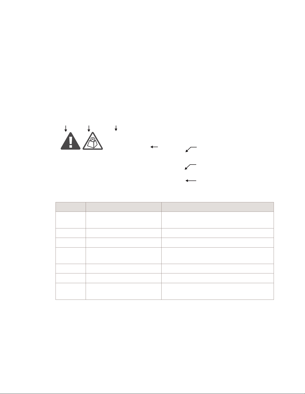
Structure of safety statements
Overview
Safety statements describe the safety risks relevant while performing tasks on
Alcatel-Lucent products during deployment and/or use. Failure to avoid the hazards may
have serious consequences.
General structure
Safety statements include the following structural elements:
BC D
CAUTION
Lifting hazard
Lifting this equipment by yourself can result in injury
due to the size and weight of the equipment.
Always use three people or a lifting device to transport
and position this equipment. [ABC123]
SAMPLE
Item Structure element Purpose
1 Safety alert symbol Indicates the potential for personal injury
2 Safety symbol Indicates hazard type (optional)
3 Signal word Indicates the severity of the hazard
4 Hazard type Describes the source of the risk of damage or
5 Safety message Consequences if protective measures fail
6 Avoidance message Protective measures to take to avoid the hazard
7 Identifier The reference ID of the safety statement
E
(optional)
injury
(optional)
F
G
H
....................................................................................................................................................................................................................................
1-2
Proprietary – Use pursuant to Company instruction
Alcatel-Lucent – Internal
9412 eNB Compact
418-000-415
Issue 4.1 August 2011
Page 15

Safety Structure of safety statements
....................................................................................................................................................................................................................................
Signal words
The signal words identify the hazard severity levels as follows:
Signal word Meaning
DANGER Indicates an extremely hazardous situation which, if not avoided, will
result in death or serious injury.
WARNING Indicates a hazardous situation which, if not avoided, could result in
death or serious injury.
CAUTION Indicates a hazardous situation which, if not avoided, could result i n
minor or moderate injury.
NOTICE Indicates a hazardous situation not related to personal injury.
Within this information product, the safety label typically includes additional information
such as the hazard type, a description of the damage that can be caused, and the steps that
should be taken to avoid the hazard.
....................................................................................................................................................................................................................................
9412 eNB Compact
418-000-415
Issue 4.1 August 2011
Proprietary – Use pursuant to Company instruction
Alcatel-Lucent – Internal
1-3
Page 16

Safety Safety - General precautions for installation procedures
....................................................................................................................................................................................................................................
Safety - General precautions for installation procedures
Overview
The following general precautions must be observed for installation procedures.
....................................................................................................................................................................................................................................
1-4
Proprietary – Use pursuant to Company instruction
Alcatel-Lucent – Internal
9412 eNB Compact
418-000-415
Issue 4.1 August 2011
Page 17

Safety Safety - General precautions for installation procedures
....................................................................................................................................................................................................................................
WARNING
Personal injury
Failure to observe these safety precautions may result in personal injury or damage to
equipment.
To avoid personal injury or damage to equipment, observe the following instructions:
• Read and understand all instructions.
• Follow all warnings and instructions marked on this product.
• Installation and maintenance procedures must be followed and performed by trained
personnel only.
• The equipment must be provided with a readily accessible disconnect device as part of
site preparation.
• Grounding and circuit continuity is vital for safe operation of the equipment. Never
operate the e quipment with grounding/bonding conductor disconnected.
• Install only equipment identified in the product's installation manual. Use of other
equipment may result in an improper connection which could lead to fire or injury.
• Use caution when installing or modifying telecommunications lines.
• The product has multiple power inputs. Before servicing, Disconnect all inputs to
reduce the risk of energy hazards.
• For continued protection against risk of fire, all fuses used in this product must be
replaced only with fuses of the same type and rating.
• Never install telecommunications wiring during a lightning storm.
• Never install telecommunications connections in wet locations.
• Never touch uninsulated telecommunications wiring or terminals unless the
telecommunications line has been disconnected at the interface.
• Never push objects of any kind into the product through slots, as they may touch
dangerous voltage points or short-out parts that could result in a fire or an electrical
short.
• Never spill liquids of any kind on the product.
• Slots and openings in the product are provided for ventilation. To protect it from
overheating, these openings must not be blocked or covered. The product should not
be placed in a built-in installation unless proper ventilation is provided.
• To reduce the risk of an electrical shock, do not disassemble the product. Opening and
removing covers and/or circuit boards may expose you to dangerous voltages or other
risks. Incorrect reassembly can cause electrical shock when the unit is subsequently
used.
....................................................................................................................................................................................................................................
9412 eNB Compact
418-000-415
Issue 4.1 August 2011
Proprietary – Use pursuant to Company instruction
Alcatel-Lucent – Internal
1-5
Page 18

Safety Safety - specific hazards
....................................................................................................................................................................................................................................
Safety - specific hazards
Overview
This topic reviews specific hazards for installation.
DANGER
Lightning Strikes!
Lightning strikes are possible during stormy weather, and could result in death or severe
injury.
Do not work on the installation itself or on the power supply lines or antenna feeders of a
Compact Cell during stormy weather.
WARNING
Energy Hazard!
Some parts of all electrical installations are energized. Failure to observe this fact and
the safety warnings may lead to bodily injury and property damage.
For this reason, only trained and qualified personnel (electrical workers as defined in
IEC 215 + A1 or EN 60215) may install or service the installation.
WARNING
Energy Hazard!
The power supply lines to the network element are energized. Short circuits can cause
burns to the face and hands.
Open the load disconnect switch in the distribution box to completely de-energize the
network element.
....................................................................................................................................................................................................................................
1-6
Proprietary – Use pursuant to Company instruction
Alcatel-Lucent – Internal
9412 eNB Compact
418-000-415
Issue 4.1 August 2011
Page 19

Safety Safety - specific hazards
....................................................................................................................................................................................................................................
WARNING
Beryllium Oxide Poisoning Hazard!
The transmitter units include components which contain beryllium oxide (BeO). In this
form, BeO ceramics do not constitute a hazardous material as long as this material is not
destroyed by external mechanical forces.
In the event that repair work is carried out by the customer or by third parties, the
following regulations must be observed:
• Applicable version of the Regulation on Hazardous Materials in the Workplace
• Appropriate accident prevention regulations.
The following must be specifically observed:
• Do not eat, drink, or smoke in areas where work is taking place on BeO ceramic
components.
• Wash your hands carefully under running water after working with BeO ceramic
components.
If the following symptoms occur, contact a physician:
• Irritation of the respiratory organs
• Difficulty breathing or skin irritation.
NOTICE
Condensation may cause a short circuit!
Sudden changes i n the weather may lead to the formation of condensation on
components. Operating the unit when condensation moisture is present can destroy the
unit.
Units which show signs of condensation must be dried before installation.
....................................................................................................................................................................................................................................
9412 eNB Compact
418-000-415
Issue 4.1 August 2011
Proprietary – Use pursuant to Company instruction
Alcatel-Lucent – Internal
1-7
Page 20

Safety Safety - specific hazards
....................................................................................................................................................................................................................................
NOTICE
Electrostatically Sensitive Components!
Semiconductor elements can be damaged by static discharges.
The following rules must be complied with when handling any module containing
semiconductor components:
• Wear conductive or antistatic work clothes (for example, a coat made of 100%
cotton).
• Wear grounded ESD wrist strap.
• Wear shoes with conductive soles.
• Leave the modules in their original packaging until ready for use.
• Make sure there is no difference in potential between yourself, the workplace, and the
package before removing, unpacking, or packing a module.
• Hold the module only by the grip without touching the connection pins, tracks, or
components.
• Place modules removed from the equipment on a conductive surface.
• Test or handle the module only with grounded tools on grounded equipment.
• Handle defective modules exactly like new ones to avoid causing further damage.
NOTICE
Grounding caution!
This equipment has a connection between the grounding conductor of the DC supply
circuit and the grounding conductor.
This equipment shall be connected directly to the DC supply system grounding electrode
conductor or to a bonding jumper from a grounding terminal bar or bus to which the DC
supply system grounding electrode conductor is connected.
This equipment shall be located in the same immediate area (such as, adjacent cabinets)
as any other equipment that has a connection between the grounded conductor of the
same DC supply circuit and the grounding conductor, and also the point of grounding of
the DC system. The DC system shall not be grounded elsewhere.
The DC supply source is to be located within the same premises as the equipment.
There shall be no switching or disconnecting devices in the grounded circuit conductor
between the DC source and the point of connection of the grounding electrode conductor.
....................................................................................................................................................................................................................................
1-8
Proprietary – Use pursuant to Company instruction
Alcatel-Lucent – Internal
9412 eNB Compact
418-000-415
Issue 4.1 August 2011
Page 21

2 2Product overview
Overview
Purpose
This chapter describes the 9412 eNodeB outdoor cabinets. This chapter also shows how
the eNodeB is used in a wireless network and describes its physical characteristics.
Then the physical characteristics of the eNodeB are discussed -- site requirements,
dimensions and weight, and the location of items and components inside the cabinet.
Installation procedures
Contents
Before installing the cabinet, the installer should become familiar with the safety
precautions, warnings, and product conformance statements. The recommended tools and
materials required for installation and the process checklist are listed i n
materials, and checklist”
Cabinet installation instructions are covered in
cabinet”
, which provides instructions for anchoring the cabinet to the floor. After
.
Chapter 4, “Transport, mount, and ground
Chapter 3, “Tools,
anchoring the cabinet, the cabinet is connected to the network with T1/E1 lines, according
to the instructions in
the user and power alarms to the cabinet are provided in
cables”
. Instructions for connecting the cabinet to a power source are given i n Chapter 6,
“Connect power cables”
Chapter 5, “Connect interface cables”. Instructions for connecting
Chapter 5, “Connect interface
. The eNodeB requires a +24 VDC power source, which can be
provided by a n external power converter or DC generator.
Instructions for connecting the cabinet to the cell antennas are given in
the installation”
Background information 2-3
Functional description 2-4
.
Chapter 7, “Finish
Physical description 2-6
...................................................................................................................................................................................................................................
9412 eNB Compact
418-000-415
Issue 4.1 August 2011
Proprietary – Use pursuant to Company instruction
Alcatel-Lucent – Internal
2-1
Page 22

Product overview Overview
....................................................................................................................................................................................................................................
9412 cabinet overview (Standard DC cabinets) 2-7
9412 cabinet overview (-48V DC Distributed cabinet) 2-9
9412 cabinet overview (AC cabinet) 2-10
9412 eNodeB overall dimensions 2-12
EZBFo battery module overview 2-14
Equipment weights and dimensions 2-16
Physical interfaces 2-18
....................................................................................................................................................................................................................................
2-2
Proprietary – Use pursuant to Company instruction
Alcatel-Lucent – Internal
9412 eNB Compact
418-000-415
Issue 4.1 August 2011
Page 23

Product overview
Background information
....................................................................................................................................................................................................................................
Overview
Background information
Overview
Purpose
The following section provides an overview of the 9412 eNodeB.
This material is provided to the installer so he can better understand the given installation
procedures.
Contents
Functional description 2-4
....................................................................................................................................................................................................................................
9412 eNB Compact
418-000-415
Issue 4.1 August 2011
Proprietary – Use pursuant to Company instruction
Alcatel-Lucent – Internal
2-3
Page 24

Product overview
Background information
....................................................................................................................................................................................................................................
Functional description
Functional description
Overview
This topic describes relevant product functional information.
Standard configuration
The standard 9412 Compact Outdoor comprises of the following two cabinets, which are
physically identical, but provide different functionality:
• BB (Baseband) cabinet
• RF (Radio Frequency) cabinet
The BB and RF cabinet are connected with CPRI fiber optic cable and an alarm cable,
both routing through the same 1-inch conduit. The alarm cable is required for DC cabinets
only.
Distributed configuration
The distributed 9412 Compact Outdoor comprises of the following:
• BB (Baseband) cabinet
• RRH (Remote Radio Head)
The BB and RRH are connected with CPRI fiber optic cable.
For the Distributed System or RRH installation, refer to Alcatel-Lucent 9442 Remote
Radio Head (RRH) 1721 MHz (AWS) Installation Manual, 418-000-427.
Product attributes
The following list the product attributes for the 9412 eNodeB.
• Flexible installation options: Floorstand/Pole/Wall mountable
• Without integrated power: (RF and BB cabinet)
• With integrated power (AC): (BB with integrated power provides DC power to RF
• Power: -48VDC (BB distributed)
- Power: +24VDC BB Cabinet and +24VDC RF Cabinet
- Power: -48VDC (BB Cabinet for Distributed System)
cabinet or RRHs).
- AC BB Cabinet Supplies +24 VDC to RF Cabinet
- AC BB Cabinet Supplies -48 VDC to RF Cabinet
• Without integrated power: (RF and BB cabinet)
• With integrated power (AC): (BB with integrated power provides DC power to RF
cabinet or RRHs).
• ?CPRI links between BB and RF cabinets or BB and RRHs
....................................................................................................................................................................................................................................
2-4
Proprietary – Use pursuant to Company instruction
Alcatel-Lucent – Internal
9412 eNB Compact
418-000-415
Issue 4.1 August 2011
Page 25

Product overview
Background information
....................................................................................................................................................................................................................................
Functional description
• The BB cabinet houses the d2U, a PDP (Power Distribution Panel), eAM (Enhanced
Alarm Module), a Fan tray, and a 2U user space depending upon the configuration
• The BB cabinet can support the SAR module
• The RF cabinet houses a PDP, a Fan tray and 3 TRDUs
• Accepts GigE fiber optic backhaul
• The system may support up to 32 user alarms
• Supports External Battery Backup (EZBFo)
• Supports public safety configuration.
....................................................................................................................................................................................................................................
9412 eNB Compact
418-000-415
Issue 4.1 August 2011
Proprietary – Use pursuant to Company instruction
Alcatel-Lucent – Internal
2-5
Page 26

Product overview
Physical description
....................................................................................................................................................................................................................................
Overview
Physical description
Overview
Purpose
This section provides an overview of the equipment inside the 9412 eNodeB.
Contents
9412 cabinet overview (Standard DC cabinets) 2-7
9412 cabinet overview (-48V DC Distributed cabinet) 2-9
9412 cabinet overview (AC cabinet) 2-10
9412 eNodeB overall dimensions 2-12
EZBFo battery module overview 2-14
Equipment weights and dimensions 2-16
Physical interfaces 2-18
....................................................................................................................................................................................................................................
2-6
Proprietary – Use pursuant to Company instruction
Alcatel-Lucent – Internal
9412 eNB Compact
418-000-415
Issue 4.1 August 2011
Page 27
Product overview
Physical description
....................................................................................................................................................................................................................................
9412 cabinet overview (Standard DC cabinets)
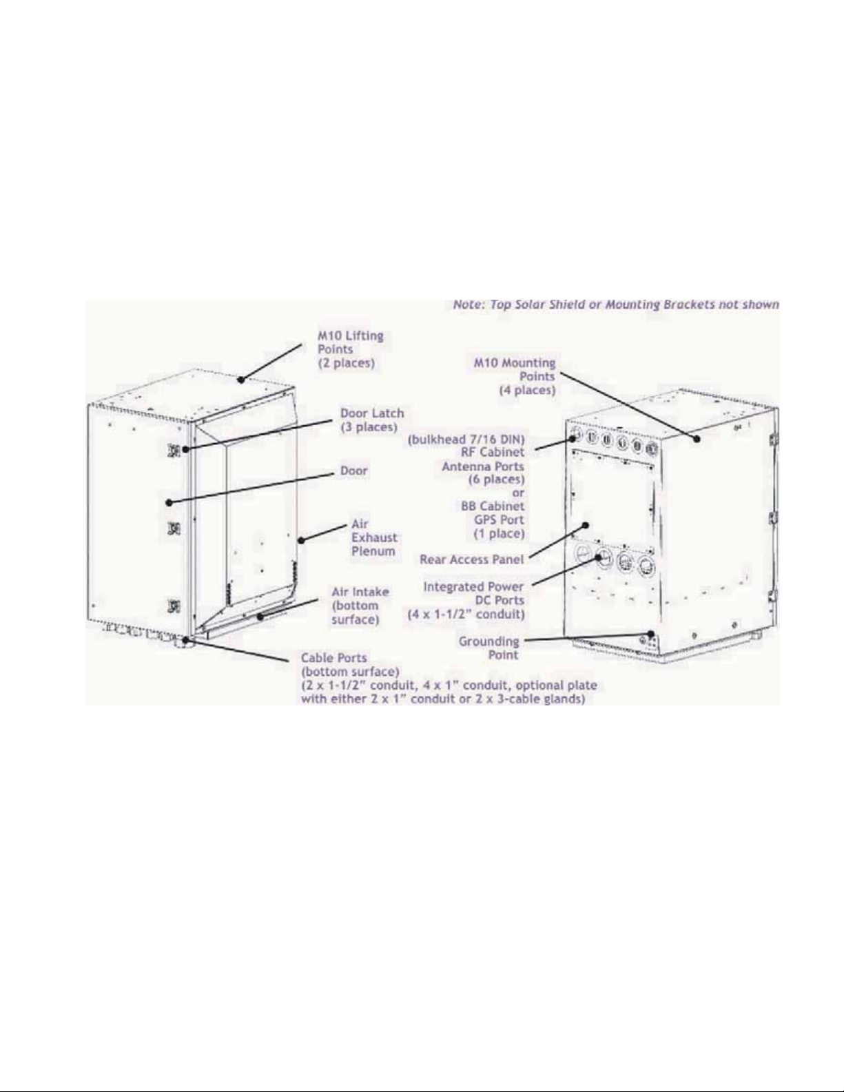
9412 cabinet overview (Standard DC cabinets)
Overview
This topic describes the various internal configurations for the cabinet.
9412 eNodeB- external view
The following diagram shows the external view for the 9412 eNodeB outdoor cabinet.
....................................................................................................................................................................................................................................
9412 eNB Compact
418-000-415
Issue 4.1 August 2011
Proprietary – Use pursuant to Company instruction
Alcatel-Lucent – Internal
2-7
Page 28
Product overview
9412 cabinet overview (Standard DC cabinets)
Physical description
....................................................................................................................................................................................................................................
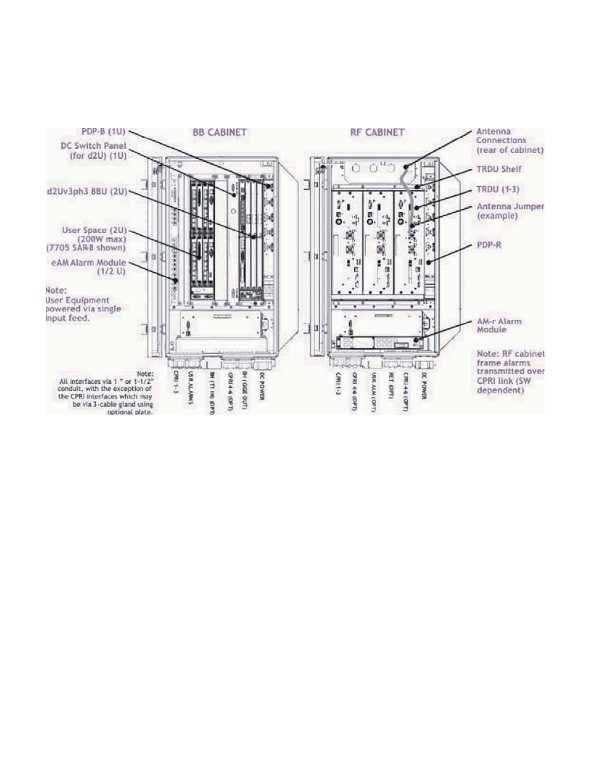
9412 eNodeB- internal view (+24 VDC version)
The following diagram shows the internal components in the 9412 eNodeB cabinet.
....................................................................................................................................................................................................................................
2-8
Proprietary – Use pursuant to Company instruction
Alcatel-Lucent – Internal
9412 eNB Compact
418-000-415
Issue 4.1 August 2011
Page 29

Product overview
Physical description
....................................................................................................................................................................................................................................
9412 cabinet overview (-48V DC Distributed cabinet)
9412 cabinet overview (-48V DC Distributed cabinet)
BB cabinet -Internal-view (DC Distributed version)
The following diagram shows the internal components in the 9412 eNodeB Distributed
cabinet (dual band).
....................................................................................................................................................................................................................................
9412 eNB Compact
418-000-415
Issue 4.1 August 2011
Proprietary – Use pursuant to Company instruction
Alcatel-Lucent – Internal
2-9
Page 30

Product overview
Physical description
....................................................................................................................................................................................................................................
9412 cabinet overview (AC cabinet)
9412 cabinet overview (AC cabinet)
AC BB cabinet and +24 V DC RF Cabinet (DC power for RF cabinet supplied by BB cabinet)
The following diagram shows the internal components in the 9412 Compact cabinet for a
+24V configuration.
....................................................................................................................................................................................................................................
2-10
Proprietary – Use pursuant to Company instruction
Alcatel-Lucent – Internal
9412 eNB Compact
418-000-415
Issue 4.1 August 2011
Page 31

Product overview
Physical description
....................................................................................................................................................................................................................................
9412 cabinet overview (AC cabinet)
AC BB cabinet and -48 V DC RF Cabinet (DC power for RF cabinet supplied by BB cabinet)
The following diagram shows the internal components in the 9412 Compact cabinet for a
-48V configuration.
....................................................................................................................................................................................................................................
9412 eNB Compact
418-000-415
Issue 4.1 August 2011
Proprietary – Use pursuant to Company instruction
Alcatel-Lucent – Internal
2-11
Page 32

Product overview
Physical description
....................................................................................................................................................................................................................................
9412 eNodeB overall dimensions
9412 eNodeB overall dimensions
9412 eNodeB -Overall Dimensions
Two following diagram shows the 9412 eNodeB outdoor cabinet with dimensions. For
more details on weights and dimensions, refer to
(p. 2-16)
“Equipment weights and dimensions”
....................................................................................................................................................................................................................................
2-12
Proprietary – Use pursuant to Company instruction
Alcatel-Lucent – Internal
9412 eNB Compact
418-000-415
Issue 4.1 August 2011
Page 33

Product overview
Physical description
....................................................................................................................................................................................................................................
9412 eNodeB overall dimensions
Dual floor-stand overall dimensions
The following diagram shows dimensions of the 9412 eNodeB cabinets configured on the
dual floor-stand
....................................................................................................................................................................................................................................
9412 eNB Compact
418-000-415
Issue 4.1 August 2011
Proprietary – Use pursuant to Company instruction
Alcatel-Lucent – Internal
2-13
Page 34

Product overview
EZBFo battery module overview
Physical description
....................................................................................................................................................................................................................................
EZBFo dimensions
The following shows the dimensions of the EZBFo:
776.2
[30.56]
614
[24 in.1]
736.6 **
ISO VIEW
(Full Assemb ly)
726.2 mm
(28.59 in.)
[29.0]
FRONT VIEW
(Full Assemb ly)
776.2
[30.56]
1456.2 mm
(57.33 in.)
730 mm
(28.74 in.)
726.2 mm
(28.59 in.)
FOOTPRINT
Swingout for
Hinged Door
FRONT
TOP
TOP VIEW
780.0
[30.71]
....................................................................................................................................................................................................................................
9412 eNB Compact
418-000-415
Proprietary – Use pursuant to Company instruction
Alcatel-Lucent – Internal
2-15
Issue 4.1 August 2011
Page 35

Product overview
Physical description
....................................................................................................................................................................................................................................
Physical interfaces
Physical interfaces
Overview
This topic covers the physical interfaces on the 9412 eNodeB outdoor cabinets, such as
RF connections, GPS connections, grounding points, and cable termination points.
Cable interfaces
The following cable interface points are found on the eNodeB:
• DC power
• AC power
• Grounding
• RF antennas (to RF cabinet)
• GPS antenna (to BB cabinet)
• User Alarm
• Fiber
....................................................................................................................................................................................................................................
2-18
Proprietary – Use pursuant to Company instruction
Alcatel-Lucent – Internal
9412 eNB Compact
418-000-415
Issue 4.1 August 2011
Page 36

Product overview
Physical interfaces
Physical description
....................................................................................................................................................................................................................................
Antenna interface
The following figure shows the antenna interface on the top-rear of the eNodeB cabinets.
....................................................................................................................................................................................................................................
9412 eNB Compact
418-000-415
Issue 4.1 August 2011
Proprietary – Use pursuant to Company instruction
Alcatel-Lucent – Internal
2-19
Page 37

Product overview
Physical interfaces
Physical description
....................................................................................................................................................................................................................................
DC cable termination points
The following figure shows the DC cable terminal block inside the RF and BB cabinets.
....................................................................................................................................................................................................................................
2-20
Proprietary – Use pursuant to Company instruction
Alcatel-Lucent – Internal
9412 eNB Compact
418-000-415
Issue 4.1 August 2011
Page 38

Product overview Physical interfaces
....................................................................................................................................................................................................................................
....................................................................................................................................................................................................................................
2-22
Proprietary – Use pursuant to Company instruction
Alcatel-Lucent – Internal
9412 eNB Compact
418-000-415
Issue 4.1 August 2011
Page 39

3 3Tools, materials, and
checklist
Overview
Purpose
This chapter provides general instructions for anchor installation and cabinet handling.
Also included a re the procedures for cabinet placement, anchoring, and grounding.
Contents
Preparatory information 3-2
Tools required for installation 3-3
Torque requirements 3-6
Physical installation process overview 3-8
Installation procedure checklist 3-9
Verify site preparation completed 3-10
...................................................................................................................................................................................................................................
9412 eNB Compact
418-000-415
Issue 4.1 August 2011
Proprietary – Use pursuant to Company instruction
Alcatel-Lucent – Internal
3-1
Page 40

Tools, materials, and checklist
Preparatory information
....................................................................................................................................................................................................................................
Overview
Preparatory information
Overview
Purpose
This section presents information and procedures that are relevant before the 9412
eNodeB can be placed, anchored, and grounded.
Also included in this section is information for verifying that site preparation
requirements have been met, so installation of the product can begin properly.
Reference documents
Further information on cabinet clearances and anchor holes can also be found in the
Alcatel-Lucent 9412 eNodeB Compact Outdoor Site Preparation Guidelines,
418-000-414.
Contents
Refer to the site-specific layout information for details on where the equipment must be
positioned.
This document also contains all necessary information on how to mark the positions of
the anchor holes and how to drill them.
Tools required for installation 3-3
Torque requirements 3-6
Physical installation process overview 3-8
Installation procedure checklist 3-9
Verify site preparation completed 3-10
....................................................................................................................................................................................................................................
3-2
Proprietary – Use pursuant to Company instruction
Alcatel-Lucent – Internal
9412 eNB Compact
418-000-415
Issue 4.1 August 2011
Page 41

Tools, materials, and checklist
Preparatory information
....................................................................................................................................................................................................................................
Tools required for installation
Tools required for installation
Overview
This section provides a master list of all tools, materials, and parts required to perform the
installation.
Tools
CAUTION
Personnel injury or equipment damage
If the installation is performed with energized DC circuits, be sure to use tools that are
properly insulated.
The following is a master list, in alphabetical order, of all tools that may be utilized
during installation:
• Adjustable open-ended wrench (or set of fixed open-ended wrenches)
• Antioxidant compound
• B connecting links, or equivalent (quantity 3)
• Bolt anchor setting tool
• Bonding clamps for facility and phone line cables (normally provided by telephone
company)
• Box cutter or equivalent for opening packages
• Chalk line
• Channel-lock pliers [for 2-1/2 inch nuts, 19 mm (3/4 inch) wide, maximum]
• Channel-lock pliers (standard)
• Crimping tools 22-16 gauge, 10-4/0 gauge (5-120 mm
2
) for installing terminal lugs
and c-taps
• Derrick, capable of lifting the cabinet
• Drill and drill bits [including 16 mm (5/8 inch) and 18 mm (11/16 inch) for drilling
anchor holes]
• Drill - Pneumatic Hammer (R-5006)
• Roto-Stop Hammer Kit (R-4416) with 1/2 inch (12 mm) chuck or equivalent to drill
anchor holes
• Ear protection gear
• Electrical conduit installation equipment and materials
• Electrical tape
....................................................................................................................................................................................................................................
9412 eNB Compact
418-000-415
Issue 4.1 August 2011
Proprietary – Use pursuant to Company instruction
Alcatel-Lucent – Internal
3-3
Page 42

Tools, materials, and checklist
Preparatory information
....................................................................................................................................................................................................................................
Tools required for installation
• ESD wrist strap
• Eye-bolts (M10/R-ITE-6111), for lifting cabinet
• Eye protection gear
• Fish tape
• Floor punch, for cutting asbestos floor tile prior to drilling
• Floor tile puller, for raised floor tiles
• Forklift, Hoist, Rol-A-Lift, or equivalent lift (non-tilt) capable of lifting and moving
the cabinet into final position
• Galvanizing paint
• Gloves -- Low-voltage rubber lineman's gloves (R-4285)
• Hammer, 0.5 kg (16 oz) for anchor installation, etc.
• Heat gun for heat shrink tubing
• Insulated gloves
• Insulated hand tools (for completing electrical connections)
• Ladder or work stand/stool so installer can access top of the cabinet and ladder rack.
Most connections are elevated. Two work platforms are required so two installers can
work efficiently.
• Level 1.5 meters (4 feet), steel
• Lifting device (R-5312) and lifting boom
• Marker, for marking floor for lineup and drilling
• Measuring tape
• Nut driver set (decimal) with 10 inch extension
• Nut driver set (metric) with 250 mm extension
• Ohmmeter (multimeter, volt/ohmmeter, or equivalent)
• Pliers
• Plumb line
• Pry bar
• Safety goggles or glasses (R-3055)
• Screwdrivers (power and manual), flat-blade, Phillips
• Silicone caulk
• Socket sets (decimal and metric) various drives
• Socket with 6”extension (to bolt cabinet to the floorstand)
• For stripping tools for jumper cables go to table for “Jumper cable and connector
stripping tools”
“Jumper cable and connector stripping tools” (p. 7-10)
• Torque wrenches,2-34Nm(17.7 - 300 in-lb)
• Torque wrenches, 6 - 200 Nm (4.4 - 150 ft-lb)
....................................................................................................................................................................................................................................
3-4
Proprietary – Use pursuant to Company instruction
Alcatel-Lucent – Internal
9412 eNB Compact
418-000-415
Issue 4.1 August 2011
Page 43

Tools, materials, and checklist
Preparatory information
....................................................................................................................................................................................................................................
Torque requirements
Metric
Screw
Size
SAE
Screw
Size
Torque - in-lb [or ft-lb] and (Nm)
Wire Connections Head Tightened Nut Tightened
Slotted
Machine
Hex or
Socket
Cap
Slotted
Machine
Hex or
Socket
Cap
Slotted
Machine
Hex or
Socket
Cap
M14 1/2-13 - 500 (56.5) - 585 (66.1) 585 (66.1) 710 (80.2)
M16 5/8-11 - [71] (96.3) - [97]
(131.5)
M20 3/4-10 - [125]
(169.5)
- [172]
(233.2)
[97]
(131.5)
[172]
(233.2)
[118]
(160.0)
[209]
(283.4)
Torque requirements for DC terminal block
The table below gives the torque requirements for the DC terminal block.
Terminal block Minimum torque (Nm) Maximum torque (Nm)
DC terminal block 6 (53 in-lb) 8 (71 in-lb)
....................................................................................................................................................................................................................................
9412 eNB Compact
418-000-415
Issue 4.1 August 2011
Proprietary – Use pursuant to Company instruction
Alcatel-Lucent – Internal
3-7
Page 44

Tools, materials, and checklist
Preparatory information
....................................................................................................................................................................................................................................
Physical installation process overview
Physical installation process overview
Overview
This topic provides the steps for installing the cabinet.
Installation process
Following are the high level steps of the installation process:
1. Verify site preparation is complete
2. Place cabinet
3. Anchor cabinet
4. Ground cabinet
5. Connect GigE backhaul fiber cable
6. Connect User Alarm cables
7. Connect AC/DC power cables
8. Install secondary GPS surge protector at BB cabinet
9. Connect GPS cable
10. Connect RF cables
11. Initial start-up & system test.
....................................................................................................................................................................................................................................
3-8
Proprietary – Use pursuant to Company instruction
Alcatel-Lucent – Internal
9412 eNB Compact
418-000-415
Issue 4.1 August 2011
Page 45

Tools, materials, and checklist
Preparatory information
....................................................................................................................................................................................................................................
Installation procedure checklist
Installation procedure checklist
Overview
The following is a procedure checklist.
Done N/A Task
“Verify site preparation completed” (p. 3-10)
“General installation procedure for twisted-pair cables” (p. 5-28)
“Route and connect User Alarm cable” (p. 5-23)
“Connect DC cables to 9412 eNodeB (+24 VDC and -48 VDC)” (p. 6-3)
“GPS jumper cable” (p. 7-2)
“RF jumper cables” (p. 7-9)
“Final connections” (p. 7-14)
....................................................................................................................................................................................................................................
9412 eNB Compact
418-000-415
Issue 4.1 August 2011
Proprietary – Use pursuant to Company instruction
Alcatel-Lucent – Internal
3-9
Page 46

Tools, materials, and checklist
Preparatory information
....................................................................................................................................................................................................................................
Verify site preparation completed
Verify site preparation completed
Overview
This topic describes what must be done to verify that the site preparation is complete so
that installation procedures can begin.
At this point, the installer must make sure that any requirements that have not been met
are met here.
Verify site preparation
Before installation of the 9412 eNodeB can begin, the site preparation must be complete,
in accordance with Alcatel-Lucent 9412 eNodeB Compact outdoor Site Preparation
Guidelines, 418-000-414.
The following general requirements must be met before the installation of the 9412
eNodeB Compact cabinet can begin:
• Adequate clearance must be provided for service access.
• GigE (fiber optic) backhaul must be installed, and capable of accepting fiber optic
Multi-Mode cable with LC connector.
• Grounding electrode system must be installed.
• RF and GPS antenna runs must be installed.
• Surge protection for RF antenna must be installed.
• Primary sure protector for GPS must be installed.
• Tower light power must be installed (if required).
• Tower light alarm must be installed (if required).
• Anchor holes must be drilled for floor stand mounting option.
• The environment must comply with limits listed in the site prep.
• Cable support structure must be installed.
• Conduits for routing cables to cabinet must be prepared.
....................................................................................................................................................................................................................................
3-10
Proprietary – Use pursuant to Company instruction
Alcatel-Lucent – Internal
9412 eNB Compact
418-000-415
Issue 4.1 August 2011
Page 47

4 4Transport, mount, and
ground cabinet
Overview
Purpose
This chapter provides general instructions for cabinet handling, cabinet placement, anchor
installation, anchoring, and grounding of the radio cabinet.
Contents
Lifting and moving cabinets 4-2
Double stack floor stand lifting brackets 4-7
Install 9412 eNodeB Compact on the floor stand 4-9
Install 9412 eNodeB Compact on the pole 4-19
Pole mounting with pole band 4-21
Install 9412 eNodeB Compact on the wall 4-25
Ground the 9412 eNodeB Compact cabinets and floor stand 4-31
...................................................................................................................................................................................................................................
9412 eNB Compact
418-000-415
Issue 4.1 August 2011
Proprietary – Use pursuant to Company instruction
Alcatel-Lucent – Internal
4-1
Page 48

Transport, mount, and ground cabinet Lifting and moving cabinets
....................................................................................................................................................................................................................................
Lifting and moving cabinets
Purpose
Cabinets are usually shipped to the customer via truck and are delivered to the installation
site. During installation, it may be necessary to lift the modular cell cabinet to move it to
a new location. This section describes how to safely lift a modular cell cabinet. Use this
information as you perform the procedures in this chapter.
Lifting machinery
To lift the cabinet, do one of the following:
• Use a forklift with forks that are at least 4 feet long to lift a cabinet that is attached to
a pallet, from the bottom.
• Install lifting eyebolts on the top of the cabinet, and use a derrick and slings to lift the
cabinet from its top.
• Use the recommended lifting device described on
(p. 4-6)
Safety precautions for using lifting machinery
WARNING
Personnel injury or equipment damage
Cabinets are too heavy to move without appropriate lifting devices.
Derrick equipment or a forklift must be used to lift the cabinet. Do not attempt to move
the cabinet manually, or remove it from the pallet manually.
WARNING
Personnel injury or equipment damage
Lifting double stack floor stand with BB and RF mounted on it.
Do NOT use the lifting points on the top of the cabinet, if lifting the double stack floor
stand with both BB and RF mounted on it. This could cause personal injury or damage to
the equipment. Lifting bracket must be used if lifting the double stack floor stand, refer to
“Double stack floor stand lifting brackets” (p. 4-7)
“Recommended lifting device”
....................................................................................................................................................................................................................................
4-2
Proprietary – Use pursuant to Company instruction
Alcatel-Lucent – Internal
9412 eNB Compact
418-000-415
Issue 4.1 August 2011
Page 49

Transport, mount, and ground cabinet Lifting and moving cabinets
....................................................................................................................................................................................................................................
Comply with the following guidelines when using lifting machinery:
• Only operators who are specifically trained and meet company requirements should
be permitted to operate derrick or forklift equipment.
• All persons working with derricks or forklifts must wear standard safety headgear,
footwear, eye protection, and insulated gloves (if required).
• Do not operate a derrick until both stabilizers are extended and firmly supported. Do
not extend stabilizers after a load is suspended from the derrick.
• While raising the derrick from the stowed position, be alert for overhead obstructions,
such as power lines, that may interfere.
• At all times, keep bystanders away from the work area.
• Operators must not suspend loads over people, nor can any person be permitted to
work, stand, or pass under a suspended load.
• When a cabinet is being lifted with slings, it is unsafe to lift the cabinet when lifting
sling angle is less than 45 degrees to the top of the cabinet.
Guidelines for using a derrick
When a derrick is used to move a cabinet, lifting eyebolts and slings are used to attach the
cabinet to the derrick.
Lifting eyebolts
Four R-ITE-6111 M10 lifting eyebolts are screwed into the eyebolt holes on the top of the
cabinet, as shown in the following figure.
Position each lifting eyebolt so that the plane of the eyebolt points at the center of the top
of the cabinet, as shown in the previous figure. When this is done, and the load is applied,
the plane of the eyebolt will align with the load. Eyebolts that are not aligned with the
load can bend as the load pulls on them sideways.
....................................................................................................................................................................................................................................
9412 eNB Compact
418-000-415
Issue 4.1 August 2011
Proprietary – Use pursuant to Company instruction
Alcatel-Lucent – Internal
4-3
Page 50

Transport, mount, and ground cabinet Lifting and moving cabinets
....................................................................................................................................................................................................................................
Observe the following guidelines about lifting eyebolts:
• The eyebolts screw into factory-installed nuts on top of the cabinet. These nuts must
be held in position while the lifting eyebolt is screwed in.
• Do not overtighten the lifting eyebolt.
• The shoulder of the lifting eyebolt must be properly seated (should bear firmly against
the mating part). If it is not, the working loads must be reduced substantially. A steel
washer or spacer may be required for proper seating.
Important! If the plane of the eyebolts does not point to the center of the cabinet after
tightening, the eyebolts may be loosen less than one turn.
• Tightness and seating must be checked after initial load.
• Lifting eyebolts should never be painted or otherwise coated, because such coatings
will cover up flaws.
Slings
Attach the slings to the boom line with a B-connecting link or clevis. Attach the other
ends of the slings to the lifting eyebolts with a B connecting link or clevis.
When a cabinet is being lifted with slings, it is unsafe to lift the cabinet when the lifting
sling angle is less than 45 degrees to the top of the cabinet. At closer than 45 degrees,
there is too much side stress on the lifting eyebolts. Use slings that are long enough to
keep the lifting sling angle at greater than 45 degrees from the top of the cabinet.
Lifting
Eyebolt
Boom line
B connecting link or clevis
Slings
Lifting sling
angle
Unsafe if lifting sling angle is
less than 45 degrees
to the top of the cabinet.
....................................................................................................................................................................................................................................
4-4
Proprietary – Use pursuant to Company instruction
Alcatel-Lucent – Internal
9412 eNB Compact
418-000-415
Issue 4.1 August 2011
Page 51

Transport, mount, and ground cabinet Lifting and moving cabinets
....................................................................................................................................................................................................................................
Control the cabinet while it is being lifted
NOTICE
When Moving Cabinet
When moving a cabinet in the following procedures, do not tilt the cabinet beyond 30
degrees from vertical. Do not stand under the cabinet.
A rope tied to the pallet attached to the cabinet should be used to guide the cabinet while
it is being lifted. The rope must be sufficiently long. As the cabinet is being lifted and
transported, use the rope to guide the cabinet and prevent the cabinet from tilting or
swinging.
Always lift cabinets carefully, and keep the boom line tight to prevent the cabinet from
tipping while it is moving. At the end of the lift, slowly place the cabinet on the ground.
....................................................................................................................................................................................................................................
9412 eNB Compact
418-000-415
Issue 4.1 August 2011
Proprietary – Use pursuant to Company instruction
Alcatel-Lucent – Internal
4-5
Page 52

Transport, mount, and ground cabinet Lifting and moving cabinets
....................................................................................................................................................................................................................................
Recommended lifting device
The following lifting truck is recommended for the 9412. The lifting devise is available
from Alcatel-Lucent (Part# R-5312).
....................................................................................................................................................................................................................................
4-6
Proprietary – Use pursuant to Company instruction
Alcatel-Lucent – Internal
9412 eNB Compact
418-000-415
Issue 4.1 August 2011
Page 53

Transport, mount, and ground cabinet Double stack floor stand lifting brackets
....................................................................................................................................................................................................................................
Double stack floor stand lifting brackets
Double stackl floor stand lifting overview
Note: The double stack floor stand with both BB and RF cabinets mounted to it, can
be lifted using lifting brackets.
....................................................................................................................................................................................................................................
9412 eNB Compact
418-000-415
Issue 4.1 August 2011
Proprietary – Use pursuant to Company instruction
Alcatel-Lucent – Internal
4-7
Page 54

Transport, mount, and ground cabinet Double stack floor stand lifting brackets
....................................................................................................................................................................................................................................
Install lifting brackets on the floor stand
WARNING
Personnel injury or equipment damage
Lifting double stack floor stand with BB and RF mounted on it.
Do NOT use the lifting points on the top of the cabinet if lifting the double stack floor
stand with both BB and RF mounted on it. This could cause personal injury or damage to
the equipment.
The lifting brackets are installed to the floor stand as shown in the following figure.
Note: The lifting sling angle at the lifting brackets should be 45°.
....................................................................................................................................................................................................................................
4-8
Proprietary – Use pursuant to Company instruction
Alcatel-Lucent – Internal
9412 eNB Compact
418-000-415
Issue 4.1 August 2011
Page 55

Transport, mount, and ground cabinet Install 9412 eNodeB Compact on the floor stand
....................................................................................................................................................................................................................................
SETTING
TOOL
...................................................................................................................................................................................................
Hold a level against the floor stand vertical upright support.
6
...................................................................................................................................................................................................
Insert combinations of 1.5 mm shims and 3 mm shims under corners of the floor stand
7
until both vertical uprights are true vertical as measured by the level.
Leveling is achieved by the use of shims. Each shim has a slot that is designed to fit
around the body of the anchor. Keep the slot properly aligned when performing this step
so that the anchor sleeves can later be set.
...................................................................................................................................................................................................
On the anchoring assembly, make sure the large plate washer, flat washer, and nut are
8
assembled, as shown in the following figure.
....................................................................................................................................................................................................................................
4-14
Proprietary – Use pursuant to Company instruction
Alcatel-Lucent – Internal
9412 eNB Compact
418-000-415
Issue 4.1 August 2011
Page 56

Transport, mount, and ground cabinet Install 9412 eNodeB Compact on the floor stand
....................................................................................................................................................................................................................................
...................................................................................................................................................................................................
Torque anchor bolts as specified in “Anchoring specifications ” (p. 4-9).
9
...................................................................................................................................................................................................
10
If ordered, install optional security cover plates on the feet of the floor stand, using
security screws.
E ND OF STEPS
...................................................................................................................................................................................................
To mount the floor stand with anchor bolts to a metal structure
Note: The following materials are required to install the cabinet on a metal support
structure.
Quantity Item
4 M12 (1/2") bolt, 60mm (2”) O. D. washer, M12 (1/2") lock washer, and
1 nut.
To install the bolts to a metal support stucture , perform the following steps.
...................................................................................................................................................................................................
Verify that the floor stand has been aligned and centered over the holes in the metal
1
support structure.
....................................................................................................................................................................................................................................
9412 eNB Compact
418-000-415
Issue 4.1 August 2011
Proprietary – Use pursuant to Company instruction
Alcatel-Lucent – Internal
4-15
Page 57

Transport, mount, and ground cabinet Install 9412 eNodeB Compact on the floor stand
....................................................................................................................................................................................................................................
...................................................................................................................................................................................................
At four places in the bottom sides of the floor stand, install a hex bolt through a flat
2
washer and then through the hole.
Make sure the 60 mm (2 inches) O.D. flat washer is underneath t he head of the bolt.
Otherwise, the bolt will not secure the floor stand.
...................................................................................................................................................................................................
Secure each bolt with a lock washer and nut.
3
...................................................................................................................................................................................................
Torque each bolt with a ratchet and deep socket to 25 ft-lb (32.2 Nm). Use a second
4
wrench to hold the nut.
E ND OF STEPS
...................................................................................................................................................................................................
....................................................................................................................................................................................................................................
4-16
Proprietary – Use pursuant to Company instruction
Alcatel-Lucent – Internal
9412 eNB Compact
418-000-415
Issue 4.1 August 2011
Page 58

Transport, mount, and ground cabinet Install 9412 eNodeB Compact on the floor stand
....................................................................................................................................................................................................................................
Install cabinet(s) on floor stand
Note: For double stack floor stand installation, remove the covers from the back of
the floor stand, and install the BB cabinet first.
Perform the following procedure to install the cabinet(s) on the floor stand.
...................................................................................................................................................................................................
Loosely attach two side M10 hex bolts, flat washers, and lock washers to the top
1
mounting holes on the back of the cabinet.
Do not tighten yet, install only halfway.
...................................................................................................................................................................................................
If you have not already done so, attach lifting harness to the two lifting points (eye bolts)
2
of the cabinet as covered in
...................................................................................................................................................................................................
3
CAUTION
“Lifting and moving cabinets” (p. 4-2).
Pinch Hazard
The bolts on the cabinet can pinch and damage your fingers. Keep fingers clear when
lowering cabinet i nto position.
Carefully raise the cabinet into position using the hoisting mechanism, if required.
...................................................................................................................................................................................................
Carefully raise the cabinet so that it can be slid back onto the floor stand. Align top.
4
...................................................................................................................................................................................................
Hang the cabinet on the top slot of the floor stand using previously installed bolts.
5
...................................................................................................................................................................................................
Attach top of the floor stand to top of the cabinet using (2) M10 hardware (bolt, flat
6
washer, and lock washer).
...................................................................................................................................................................................................
Install two M10 bolts with washers at the lower mounting holes of the cabinet.
7
...................................................................................................................................................................................................
Use torque wrench to tighten all the bolts to 32.2 Nm (25 ft-lbs).
8
....................................................................................................................................................................................................................................
9412 eNB Compact
418-000-415
Issue 4.1 August 2011
Proprietary – Use pursuant to Company instruction
Alcatel-Lucent – Internal
4-17
Page 59

Transport, mount, and ground cabinet Install 9412 eNodeB Compact on the floor stand
....................................................................................................................................................................................................................................
E ND OF STEPS
...................................................................................................................................................................................................
....................................................................................................................................................................................................................................
4-18
Proprietary – Use pursuant to Company instruction
Alcatel-Lucent – Internal
9412 eNB Compact
418-000-415
Issue 4.1 August 2011
Page 60

6 6Connect power cables
Overview
Purpose
The following chapter shows how to connect power cables to the 9412 eNodeB.
Contents
Connect DC and AC power 6-2
Connect DC cables to 9412 eNodeB (+24 VDC and -48 VDC) 6-3
Connect DC power between RF and BB cabinet (AC configuration) 6-8
Connect DC power between RRH and BB cabinet (Distributed configuration) 6-11
Route and connect the AC cable 6-13
...................................................................................................................................................................................................................................
9412 eNB Compact
418-000-415
Issue 4.1 August 2011
Proprietary – Use pursuant to Company instruction
Alcatel-Lucent – Internal
6-1
Page 61

Connect power cables
Connect DC and AC power
....................................................................................................................................................................................................................................
Overview
Connect DC and AC power
Overview
Purpose
The following section covers the procedures for connecting DC power to the 9412
eNodeB.
Contents
Connect DC cables to 9412 eNodeB (+24 VDC and -48 VDC) 6-3
Connect DC power between RF and BB cabinet (AC configuration) 6-8
Connect DC power between RRH and BB cabinet (Distributed configuration) 6-11
Route and connect the AC cable 6-13
....................................................................................................................................................................................................................................
6-2
Proprietary – Use pursuant to Company instruction
Alcatel-Lucent – Internal
9412 eNB Compact
418-000-415
Issue 4.1 August 2011
Page 62

Connect power cables
Connect DC and AC power
....................................................................................................................................................................................................................................
Connect DC cables to 9412 eNodeB (+24 VDC and -48 VDC)
Connect DC cables to 9412 eNodeB (+24 VDC and -48 VDC)
Overview
The following topic provides the procedure for connecting DC cables to the RF and BB
cabinet.
The RF and BB cabinet accepts one DC feeder cable. The DC feeder cable is (1AWG),
stranded copper wire.
....................................................................................................................................................................................................................................
9412 eNB Compact
418-000-415
Issue 4.1 August 2011
Proprietary – Use pursuant to Company instruction
Alcatel-Lucent – Internal
6-3
Page 63

Connect power cables
Connect DC and AC power
....................................................................................................................................................................................................................................
Connect DC cables to 9412 eNodeB (+24 VDC and -48 VDC)
+24 VDC cable connections
The following table provides information about the +24 VDC feeder cable connections on
each BB and RF cabinets.
Purpose Wire size Label on terminal block and wire color
Feeder 1 1 AWG FEED 1 +24 V
RTN
-48 VDC cable connections
The following table provides information about the -48 VDC feeder cable connections on
the BB and RF cabinets.
Purpose Wire size Label on terminal block and wire color
Feeder 1 1 AWG FEED 1 -48 V
RTN
....................................................................................................................................................................................................................................
6-4
Proprietary – Use pursuant to Company instruction
Alcatel-Lucent – Internal
9412 eNB Compact
418-000-415
Issue 4.1 August 2011
Page 64

Connect power cables
Connect DC and AC power
....................................................................................................................................................................................................................................
Connect DC cables to 9412 eNodeB (+24 VDC and -48 VDC)
DC terminal block
The following figure shows the DC terminal block at the front, lower-right of the eNodeB
cabinets.
Before you begin
Make sure power at DC source is turned off.
....................................................................................................................................................................................................................................
9412 eNB Compact
418-000-415
Issue 4.1 August 2011
Proprietary – Use pursuant to Company instruction
Alcatel-Lucent – Internal
6-5
Page 65

Connect power cables
Connect DC and AC power
....................................................................................................................................................................................................................................
Connect DC cables to 9412 eNodeB (+24 VDC and -48 VDC)
Route and connect DC power cables for the RF and BB cabinet
Perform the following procedure to connect the DC power cables to the eNodeB:
...................................................................................................................................................................................................
Route the DC power cables via 1-1/2” conduit through the eNodeB to the DC terminal
1
block located on the lower-right inside the RF and BB cabinet.
Note: The DC conduit must use an LB connector at the DC entry port as shown.
...................................................................................................................................................................................................
Cut each DC power cable to appropriate length so it reaches the terminals on the DC
2
terminal block. Strip 20 mm (0.8 in) of insulation from the end of each DC power cable.
The terminals on the DC terminal block are labeled as follows:
• FEED 1 (+24 V and RTN)
• FEED 1 (-48 V and RTN)
....................................................................................................................................................................................................................................
6-6
Proprietary – Use pursuant to Company instruction
Alcatel-Lucent – Internal
9412 eNB Compact
418-000-415
Issue 4.1 August 2011
Page 66

Connect power cables
Connect DC and AC power
....................................................................................................................................................................................................................................
Connect DC cables to 9412 eNodeB (+24 VDC and -48 VDC)
Important! Check polarity of cables before connecting to terminal blocks.
...................................................................................................................................................................................................
Insert the end of each DC power cable into its corresponding terminal and torque each
3
terminal to 6 to 8 Nm (57 to 71 in-lb), using a 3/16-inch wide, flat blade screwdriver.
E ND OF STEPS
...................................................................................................................................................................................................
....................................................................................................................................................................................................................................
9412 eNB Compact
418-000-415
Issue 4.1 August 2011
Proprietary – Use pursuant to Company instruction
Alcatel-Lucent – Internal
6-7
Page 67

Connect power cables
Connect DC and AC power
....................................................................................................................................................................................................................................
Connect DC power between RF and BB cabinet (AC
configuration)
Connect DC power between RF and BB cabinet (AC
configuration)
Route and connect DC cables between RF and BB cabinet
Note: If connecting DC power between the RRH and BB cabinet refer to “Connect
DC power between RRH and BB cabinet (Distributed configuration)” (p. 6-11)
Perform the following procedures to connect DC power between the RF and BB cabinet.
...................................................................................................................................................................................................
Connect LB and conduit connectors to the DC entry port on the rear of the RF and BB
1
cabinet.
....................................................................................................................................................................................................................................
6-8
Proprietary – Use pursuant to Company instruction
Alcatel-Lucent – Internal
9412 eNB Compact
418-000-415
Issue 4.1 August 2011
Page 68

Connect power cables
Connect DC and AC power
....................................................................................................................................................................................................................................
Connect DC power between RF and BB cabinet (AC
configuration)
...................................................................................................................................................................................................
Cut the required flexible conduit to sufficient length to fit between the cabinets.
2
....................................................................................................................................................................................................................................
9412 eNB Compact
418-000-415
Issue 4.1 August 2011
Proprietary – Use pursuant to Company instruction
Alcatel-Lucent – Internal
6-9
Page 69

Connect power cables
Connect DC and AC power
....................................................................................................................................................................................................................................
...................................................................................................................................................................................................
Connect the flexible conduit to the two installed LB connectors.
3
...................................................................................................................................................................................................
Remove plastic cover from the DC distribution panel on the rear of the BB cabinet.
4
...................................................................................................................................................................................................
Connect the DC cable lugs to Feed 1 (Red) and RTN (Black).
5
...................................................................................................................................................................................................
Connect the loose end of the DC cable to the DC terminal block inside the RF cabinet.
6
E ND OF STEPS
...................................................................................................................................................................................................
Connect DC power between RF and BB cabinet (AC
configuration)
....................................................................................................................................................................................................................................
6-10
Proprietary – Use pursuant to Company instruction
Alcatel-Lucent – Internal
9412 eNB Compact
418-000-415
Issue 4.1 August 2011
Page 70

Connect power cables
Connect DC and AC power
....................................................................................................................................................................................................................................
Connect DC power between RRH and BB cabinet
(Distributed configuration)
Connect DC power between RRH and BB cabinet (Distributed
configuration)
Route and connect DC cables between RRH and BB cabinet
Perform the following procedures to connect DC power between the RRH and BB
cabinet.
...................................................................................................................................................................................................
Install 11/2” to 1” conduit Reducer at the DC entry port on the rear of the BB cabinet.
1
BB
Install 11/2 to 1 Reducer
at DC entry
1-inch conduit
for DC cables
REAR
DC cable
to RRH1
DC cable
to RRH2
...................................................................................................................................................................................................
Cut the required 1-inch flexible conduit to sufficient length to fit between the BB and
2
DC cable
to RRH3
RRH(s).
...................................................................................................................................................................................................
Connect the flexible conduit to the installed Reducer.
3
...................................................................................................................................................................................................
Remove plastic cover from the DC distribution panel on the rear of the BB cabinet.
4
...................................................................................................................................................................................................
Connect the DC cable lugs to Feed 1 (Red) and RTN (Black).
5
....................................................................................................................................................................................................................................
9412 eNB Compact
418-000-415
Issue 4.1 August 2011
Proprietary – Use pursuant to Company instruction
Alcatel-Lucent – Internal
6-11
Page 71

Connect power cables
Connect DC and AC power
....................................................................................................................................................................................................................................
...................................................................................................................................................................................................
Connect the loose end of the DC cable to the DC terminal on the RRH.
6
...................................................................................................................................................................................................
To connect the DC cable to the RRH, refer to the appropriate RRH installation manual.
7
Connect DC power between RRH and BB cabinet
(Distributed configuration)
9442 RRH installation manual:
• 9442 RRH (AWS) Installation manual, 418-000-426
• 9442 RRH (700 MHz- Lower Band) Installation manual, 418-000-424
E ND OF STEPS
...................................................................................................................................................................................................
....................................................................................................................................................................................................................................
6-12
Proprietary – Use pursuant to Company instruction
Alcatel-Lucent – Internal
9412 eNB Compact
418-000-415
Issue 4.1 August 2011
Page 72

Connect power cables
Connect DC and AC power
....................................................................................................................................................................................................................................
Route and connect the AC cable
Route and connect the AC cable
Overview
The following topic covers the routing and connection AC cable in the 9412 Compact
cabinet.
Route and connect the AC cable in the BB cabinet
Perform the following steps to route and connect the three-wire AC cable to the Phoenix
terminal blocks and ground point in the 9412 Compact cabinet.
...................................................................................................................................................................................................
Route and dress the cable from its conduit entry point, to the Phoenix terminal block
1
location at t he bottom front of the BB cabinet. Refer to the following figure.
...................................................................................................................................................................................................
Remove the cover from the AC terminal blocks. Refer to the following figure.
2
....................................................................................................................................................................................................................................
9412 eNB Compact
418-000-415
Issue 4.1 August 2011
Proprietary – Use pursuant to Company instruction
Alcatel-Lucent – Internal
6-13
Page 73

Connect power cables
Connect DC and AC power
....................................................................................................................................................................................................................................
Route and connect the AC cable
...................................................................................................................................................................................................
Fan out the wires and lead them to the correct terminals. Refer to the following figure and
3
table.
AC TERMINAL BLOCK CONNECTIONS
PE
AC
INPUT
SIDE
L2/N
L1
AC/ +24v BB Cabinet
AC/ -48v BB Cabinet
...................................................................................................................................................................................................
Route the 25 inch ground wire from the end of the AC cable to the AC terminal block.
4
PE
L2/N
L1
L1
L1
....................................................................................................................................................................................................................................
6-14
Proprietary – Use pursuant to Company instruction
Alcatel-Lucent – Internal
9412 eNB Compact
418-000-415
Issue 4.1 August 2011
Page 74

Connect power cables
Connect DC and AC power
....................................................................................................................................................................................................................................
...................................................................................................................................................................................................
Attach the ring terminal lug to the screw hole with the supplied M5 screw and connect the
5
Route and connect the AC cable
ground wire to the ground point on the AC terminal block.
...................................................................................................................................................................................................
Connect the AC wires (L1 and L2/N) to the Phoenix terminal blocks on the AC terminal
6
as indicated in the table below. Refer to the
Step 3 figure for an illustration of the terminal
blocks.
+24V Terminal Block
AC cable wire
color
Terminal block
label
Function Block Position and
Color
North America and compatible markets
Red L1 L1 1 (Gray)
Black L2/N L2 2 (Blue)
Green PE GND 3 (Yellow/Green)
-48V Terminal Block
Terminal block label Function Block Position and Color
L1 L1, L1,L1 (these terminals are
1,2.3 (Gray)
jumpered)
L2/N L2 4 (Blue)
PE GND 5 (Yellow/Green)
...................................................................................................................................................................................................
Torque the screws to 1.5 to 1.8 Nm (13 to 16 in.-lb).
7
E ND OF STEPS
...................................................................................................................................................................................................
....................................................................................................................................................................................................................................
9412 eNB Compact
418-000-415
Issue 4.1 August 2011
Proprietary – Use pursuant to Company instruction
Alcatel-Lucent – Internal
6-15
Page 75

Connect power cables Route and connect the AC cable
....................................................................................................................................................................................................................................
....................................................................................................................................................................................................................................
6-16
Proprietary – Use pursuant to Company instruction
Alcatel-Lucent – Internal
9412 eNB Compact
418-000-415
Issue 4.1 August 2011
Page 76

Finish the installation
Final connections
....................................................................................................................................................................................................................................
Overview
Final connections
Overview
Purpose
This section addresses the final connections to be made after installation of the eNodeB
has been completed.
Contents
Initial start-up and system test 7-15
Final cabinet installation procedures 7-16
....................................................................................................................................................................................................................................
7-14
Proprietary – Use pursuant to Company instruction
Alcatel-Lucent – Internal
9412 eNB Compact
418-000-415
Issue 4.1 August 2011
Page 77

Finish the installation
Final connections
....................................................................................................................................................................................................................................
Initial start-up and system test
Initial start-up and system test
Important! The procedures for initial start-up and test are not covered in this
document. Refer to Integration Engineering Handbook, IEH 401.
Before initial start-up and test
To perform initial start-up and system test, the RF jumper cables will be temporarily
disconnected at the eNodeB by the personnel who perform initial start-up and system test.
After performing initial start-up and system test, the personnel will permanently connect
the RF j umper cables to the eNodeB.
After initial start-up and test
NOTICE
RF hazard!
If it is necessary to disconnect an RF jumper cable, make sure there is no transmit signal
in the RF jumper cable.
...................................................................................................................................................................................................
Once initial start-up and test have been completed, make sure the RF jumper cables are
1
properly connected to the radio cabinet. Refer to Connect RF jumper cables to eNodeB on
page 7-9.
...................................................................................................................................................................................................
2
Important! Hold the body of the 90 degree connector (part connected to the entry
cable) with a 22 mm open-end wrench. Torque the rotating nut with a 32 mm
open-end wrench.
Torque each RF connector at the radio cabinet to 25 Nm (221 in-lb).
...................................................................................................................................................................................................
Finally, secure the RF jumper cables along their route.
3
E ND OF STEPS
...................................................................................................................................................................................................
....................................................................................................................................................................................................................................
9412 eNB Compact
418-000-415
Issue 4.1 August 2011
Proprietary – Use pursuant to Company instruction
Alcatel-Lucent – Internal
7-15
Page 78

Finish the installation
Final connections
....................................................................................................................................................................................................................................
Final cabinet installation procedures
Final cabinet installation procedures
Overview
This topic describes the tasks that must be completed to finish installation of the eNodeB.
System test
Following installation of the eNodeB, the system should be tested before being put it into
operation. System test procedures are not covered in this installation document.
Information concerning system test and integration is contained in Integration
Engineering Handbook (IEH) 401.
Ensure that it is safe to turn on eNodeB
Use the following procedure to ensure the eNodeB can be turned on.
...................................................................................................................................................................................................
Inspect for loose tools, materials, and parts. Remove all such loose tools, materials, and
1
parts.
...................................................................................................................................................................................................
Verify that all the cable connections are secure.
2
E ND OF STEPS
...................................................................................................................................................................................................
Power up eNodeB
Use the following procedure to power up the eNodeB.
...................................................................................................................................................................................................
Turn on the DC circuit breakers at the DC power source.
1
...................................................................................................................................................................................................
Turn on the AC heaters, if available.
2
E ND OF STEPS
...................................................................................................................................................................................................
....................................................................................................................................................................................................................................
7-16
Proprietary – Use pursuant to Company instruction
Alcatel-Lucent – Internal
9412 eNB Compact
418-000-415
Issue 4.1 August 2011
Page 79

Appendix C: Product
conformance statements
Overview
Purpose
This section presents the product conformance statements that apply to the eNodeB
Compact cabinet.
In regions such as North America and the European Union, the statements that are
required are determined primarily by national or multi-national regulations. However, in
some regions, contract terms determine which statements are required.
The presence of the statement indicates that the product does comply with that statement
wherever it is required to do so.
Contents
Canada C-2
European Union C-5
United States C-9
...................................................................................................................................................................................................................................
9412 eNB Compact
418-000-415
Issue 4.1 August 2011
Proprietary – Use pursuant to Company instruction
Alcatel-Lucent – Internal
C-1
Page 80

Product conformance statements Canada
....................................................................................................................................................................................................................................
Canada
Introduction
The statements that follow are the product conformance statements that apply to the 9412
eNodeB when deployed in Canada.
Industry Canada
ICES-003: Interference-Causing Equipment Standard Digital Apparatus
This Class A digital apparatus complies with Canadian ICES-003.
Cet appareil numérique de la classe A est conforme à la norme NMB-003 du Canada.
IC CS-03: Specification for Terminal Equipment, Terminal Systems, Network
Protection Devices, Connection Arrangements and Hearing Aids Compatibility
This product meets the applicable Industry Canada technical specifications.
RF approval
• RSS-132: Cellular Telephones Employing New Technologies Operating in the Bands
824-849 MHz and 869-894 MHz
The term “IC” before the certification/registration number only signifies that the
Industry Canada technical specifications were met.
• RSS-133: PCS Radio Standards Specifications
The term “IC” before the certification/registration number only signifies that the
Industry Canada technical specifications were met.
Product safety conformance
This product is safety certified for Canada by a laboratory accredited by the Standards
Council of Canada (SCC), such as CSA, UL, or others. The product bears this
certification mark of this certification laboratory on its main nameplate label. Should the
local authority having jurisdiction (AHJ) require prior or additional verification of this
certification, a product certificate of compliance can be obtained from the specific
certification laboratory by the business/product unit Applicant for the product.
Any modifications to this equipment are not permitted without review and written official
authorization from the specific certification laboratory. Unauthorized changes may violate
the product safety certification. Modifications or changes authorized by official CN/CNN
are assumed to have received prior approval from this Lab.
The distributed cabinet has been listed with CSA to install only the following auxiliary
equipment in the 9412 cabinet user space.
• Tellabs 8605 Access Switch
• Kathrein 860 10006 CCU (Central Control Unit for Remote Electrical Tilt) RET.
....................................................................................................................................................................................................................................
C-2
Proprietary – Use pursuant to Company instruction
Alcatel-Lucent – Internal
9412 eNB Compact
418-000-415
Issue 4.1 August 2011
Page 81

Product conformance statements Canada
....................................................................................................................................................................................................................................
Antenna exposure
Antenna installations for the 9412 eNodeB shall be performed in accordance with all
applicable manufacturer's recommendations, and national laws and regulations. To ensure
correct antenna installation, the antenna installer shall perform all necessary calculations
and/or field measurements to evaluate compliance with applicable national laws or
regulations regarding exposure to electromagnetic fields. The supplier of radio
equipment, the supplier of antenna equipment and the integrator and builder of the site
must provide sufficient information so that the limits of the exclusion zones can be
determined. Any changes to the antenna or other equipment in the transmit path may
require re-evaluation of the exposures to electromagnetic fields.
Human exposure
Pursuant to Health Canada Safety Code 6, Limits of Human Exposure to Radio frequency
Electromagnetic Fields in the Frequency Range from 3 kHz to 300 GHz, all installations
must be evaluated against the Maximum Exposure Limits as described in Chapter 2,
Health Canada 99-EHD-237.
Optical transmitters
Alcatel-Lucent declares that 9412 eNodeB complies with the International
Electrotechnical Commission (IEC) standards IEC 60825-1 Edition 2.0 (2007) and IEC
60825-2 Edition 3.1 (2007). It is a Class I/1 laser optical fiber communication systems
"product" under the IEC classifications.
This product is designed to ensure that personnel operating the product are not
endangered by laser radiation during normal operation and fault conditions. This product
does not present a risk of eye injury because it is fully enclosed and does not contain
embedded lasers greater than Class I/1 unless otherwise noted.
Use of controls or adjustments or performance of procedures other than those specified
herein may result in hazardous laser radiation exposure.
Do not view directly into the laser beam with optical instruments such as a fiber
microscope because viewing of laser emission in excess of Class 1 limits significantly
increases the risk of eye damage.
CAUTION
Laser hazard
Never look into the end of an exposed fiber or an open connector as long as the optical
source is switched on.
Ensure that the optical source is switched off before disconnecting optical fiber
connectors.
....................................................................................................................................................................................................................................
9412 eNB Compact
418-000-415
Issue 4.1 August 2011
Proprietary – Use pursuant to Company instruction
Alcatel-Lucent – Internal
C-3
Page 82

Product conformance statements Canada
....................................................................................................................................................................................................................................
Packaging collection and recovery requirements
Countries, states, localities, or other jurisdictions may require that systems be established
for the return and/or collection of packaging waste from the consumer, or other end user,
or from the waste stream. Additionally, reuse, recovery, and/or recycling targets for the
return and/or collection of the packaging waste may be established.
For more information regarding collection and recovery of packaging and packaging
waste within specific jurisdictions, please contact the Alcatel-Lucent Services Environmental Health and Safety organization. For installations not performed by
Alcatel-Lucent Technologies, please contact the Alcatel-Lucent Customer Support Center
at:
Technical Support Services, within Canada: +1 630 224 4672, prompt 2
....................................................................................................................................................................................................................................
C-4
Proprietary – Use pursuant to Company instruction
Alcatel-Lucent – Internal
9412 eNB Compact
418-000-415
Issue 4.1 August 2011
Page 83

Product conformance statements European Union
....................................................................................................................................................................................................................................
European Union
Introduction
The statements that follow are the product conformance statements that apply to the 9412
eNodeB bearing the CE Marking and when deployed in the European Union.
Declaration of Conformity for radio and telecommunication terminal equipment under the scope
of Directive 1999/5/EC
Hereby, Alcatel-Lucent declares that the equipment documented in this publication is in
compliance with the essential requirements and other relevant provisions of Directive
1999/5/EC.
The technical documentation as required by the Conformity Assessment procedure is kept
at the Alcatel-Lucent location which is responsible for this product. For more information
please contact your local Alcatel-Lucent Customer Service Organization.
CE marking
This product has been CE-marked in accordance with the following European Directive:
• Radio and Telecommunication Terminal Equipment (R&TTE) 1999/5/EC
EMC and radio spectrum compliance for the 850 MHz p roduct
The equipment complies with the following EMC and radio spectrum specifications:
• EN 60950-1
• EN 60215
EMC and radio spectrum compliance for the 450 MHz p roduct
The equipment complies with the following EMC and radio spectrum specifications:
• ETSI EN 301 449 V1.1.1 (2005-05)
• ETSI EN 301 489-1 V1.6.1 (2005-09)
• Code of Federal Regulations FCC part 24(E)
• IS 3GPP2 - C.S0010-B
Product safety conformance
The equipment complies with the following product safety specifications:
• EN 60950-1:2001
• EN 60215:1989
Telecommunications Standards
The equipment complies with the following telecommunication specifications:
• Technical Basis Regulation TBR 13
....................................................................................................................................................................................................................................
9412 eNB Compact
418-000-415
Issue 4.1 August 2011
Proprietary – Use pursuant to Company instruction
Alcatel-Lucent – Internal
C-5
Page 84

Product conformance statements European Union
....................................................................................................................................................................................................................................
Antenna exposure
Antenna installations for the 9412 eNodeB shall be performed in accordance with all
applicable manufacturer's recommendations, and national laws and regulations. To ensure
correct antenna installation, the antenna installer shall perform all necessary calculations
and/or field measurements to evaluate compliance with applicable national laws or
regulations regarding exposure to electromagnetic fields. The supplier of radio
equipment, the supplier of antenna equipment and the integrator and builder of the site
must provide sufficient information so that the limits of the exclusion zones can be
determined. Any changes to the antenna or other equipment in the transmit path may
require re-evaluation of the exposures to electromagnetic fields.
Pursuant to
• European Council Recommendation 1999/519/EC “On the limitation of exposure of
the general public to electromagnetic fields” dated 12 July 1999 and
• ICNIRP (International Commission on Non-Ionising Radiation Protection)
“Guidelines for limiting exposure to time-varying electric, magnetic, and
electromagnetic fields”,
all installations must be evaluated against the Reference Levels, and if necessary
exclusion zones for public and installation workers defined.
The following information on Alcatel-Lucent supplied equipment is available from
customer representatives:
• Output power and antenna characteristic, if t he product is equipped with an integral
antenna.
• A detailed description of at least one typical normal configuration, including antenna
system (feeders, connectors, combiners, antennas etc.), if the product is intended to be
used with external antennas.
• Limit distances for general public and occupational exposure. If the product is
intended for use with external antennas, limit distances shall be given for the given
typical system configurations.
• Information how to specify exposure levels and limit distances for any optional
system configuration not specified in detail.
• Information on how to install the equipment/system or the external antennas in order
to ensure that the separation between the radiating antenna and general public are
exceeding the maximum allowed distances.
Information on the methodology used for the determination of RF safety compliance
distances and exclusion zones, and the results of the compliance evaluation shall be
available for inspection by officials of the governing authorities.
....................................................................................................................................................................................................................................
C-6
Proprietary – Use pursuant to Company instruction
Alcatel-Lucent – Internal
9412 eNB Compact
418-000-415
Issue 4.1 August 2011
Page 85

Product conformance statements European Union
....................................................................................................................................................................................................................................
Optical transmitters
Alcatel-Lucent declares that 9412 eNodeB complies with the CENELEC standards EN
60825-1 Edition 1994 and its amendment 1 (2002) and amendment 2 (2001) and EN
60825-2 Edition 2004. It is a Class I/1 laser optical fiber communication systems
“product” under t he IEC classifications.
This product is designed to ensure that personnel operating the product are not
endangered by laser radiation during normal operation and fault conditions. This product
does not present a risk of eye injury because it is fully enclosed and does not contain
embedded lasers greater than Class I/1 unless otherwise noted.
CAUTION
Laser hazard
Use of controls or adjustments or performance of procedures other than those specified
herein may result in hazardous laser radiation exposure.
Do not view directly into the laser beam with optical instruments such as a fiber
microscope because viewing of laser emission in excess of Class 1 limits significantly
increases the risk of eye damage.
Never look into the end of an exposed fiber or an open connector as long as the optical
source is switched on.
Ensure that the optical source is switched off before disconnecting optical fiber
connectors.
Packaging collection and recovery requirements
Countries, states, localities, or other jurisdictions may require that systems be established
for the return and/or collection of packaging waste from the consumer, or other end user,
or from the waste stream. Additionally, reuse, recovery, and/or recycling targets for the
return and/or collection of the packaging waste may be established.
For more information regarding collection and recovery of packaging and packaging
waste within specific jurisdictions, please contact the Alcatel-Lucent Services Environmental Health and Safety organization. For installations not performed by
Alcatel-Lucent Technologies, please contact the Alcatel-Lucent Customer Support Center
at:
Technical Support Services, from all other countries: +1 630 224 4672, prompt 2
....................................................................................................................................................................................................................................
9412 eNB Compact
418-000-415
Issue 4.1 August 2011
Proprietary – Use pursuant to Company instruction
Alcatel-Lucent – Internal
C-7
Page 86

Product conformance statements European Union
....................................................................................................................................................................................................................................
Recycling / take-back / disposal of product
Electronic products bearing or referencing the symbol shown below when put on the
market within the European Union, shall be collected and treated at the end of their useful
life, in compliance with applicable European Union and local legislation. They shall not
be disposed of as part of unsorted municipal waste. Due to materials that may be
contained in the product, such as heavy metals or batteries, the environment and human
health may be negatively impacted as a result of inappropriate disposal.
Important! In the European Union, a solid bar under the crossed-out wheeled bin
indicates that the product was put on the market after 13 August 2005.
Moreover, in compliance with legal requirements and contractual agreements, where
applicable, Alcatel-Lucent will offer to provide for the collection and treatment of
Alcatel-Lucent products bearing the logo at the end of their useful life, or products
displaced by Alcatel-Lucent equipment offers. For information regarding take-back of
equipment by Alcatel-Lucent, or for more information regarding the requirements for
recycling/disposal of product, please contact your Alcatel-Lucent Account Manager or
Alcatel-Lucent Takeback Support at:
takeback@alcatel-lucent.com.
Material content compliance
European Union (EU) Directive 2002/95/EC, “Restriction of the use of certain Hazardous
Substances” (RoHS), restricts the use of lead, mercury, cadmium, hexavalent chromium,
and certain flame retardants in electrical and electronic equipment. This Directive applies
to electrical and electronic products placed on the EU market after 1 July 2006, with
various exemptions, including an exemption for lead solder in network infrastructure
equipment. Alcatel-Lucent products shipped to the EU after 1 July 2006 comply with the
EU RoHS Directive.
....................................................................................................................................................................................................................................
C-8
Proprietary – Use pursuant to Company instruction
Alcatel-Lucent – Internal
9412 eNB Compact
418-000-415
Issue 4.1 August 2011
Page 87

Product conformance statements United States
....................................................................................................................................................................................................................................
United States
Introduction
The statements that follow are the product conformance statements that apply to the 9412
eNodeB when deployed in the United States.
Federal Communications Commission
Important! Changes or modifications not expressly approved by Alcatel-Lucent, Inc.
could void the user's authority to operate the equipment.
.
FCC Part 15
This device complies with Part 15 of the FCC Rules. Operation is subject to the following
two conditions: (1) This device may not cause harmful interference, and (2) this device
must accept any interference received, including interference that may cause undesired
operation.
FCC Part 15 Class A (as marketed)
Important! This equipment has been tested and found to comply with the limits for a
Class A digital device, pursuant to Part 15 of the FCC Rules. These limits are
designed to provide reasonable protections against harmful interference when the
equipment is operated in a commercial environment. This equipment generates, uses,
and can radiate radio frequency energy and, if not installed and used in accordance
with the instruction manual, may cause harmful interference to radio communications.
Operation of this equipment in a residential area is likely to cause harmful
interference, in which case the user will be required to correct the interference at the
user's expense.
FCC Part 15 Class B (as marketed)
Important! This equipment has been tested and found to comply with the limits for a
Class B digital device, pursuant to Part 15 of the FCC Rules. These limits are
designed to provide reasonable protection against harmful interference in a residential
installation. This equipment generates, uses, and can radiate radio frequency energy
and, if not installed and used in accordance with the instructions, may cause harmful
interference to radio communications. However, there is no guarantee that
interference will not occur in a particular installation. If this equipment does cause
harmful interference to radio or television reception, which can be determined by
turning the equipment off and on, the user is encouraged to try to correct the
interference by one or more of the following measures:
• Reorient or relocate the receiving antenna
• Increase the separation between the equipment and receiver
....................................................................................................................................................................................................................................
9412 eNB Compact
418-000-415
Issue 4.1 August 2011
Proprietary – Use pursuant to Company instruction
Alcatel-Lucent – Internal
C-9
Page 88

Product conformance statements United States
....................................................................................................................................................................................................................................
• Connect the equipment into an outlet on a circuit different from that to which the
receiver is connected
• Consult the dealer or an experienced radio/TV technician for help.
FCC Part 68
This equipment complies with Part 68 of the FCC rules and the requirements adopted by
the ACTA. On the cabinet assembly of this equipment is a label that contains, among
other information, a product identifier in the format of AAAEQ##TXXXX. If requested,
this number must be provided to the telephone company.
• FIC 04DU9-1SN
• SOC 6.0N
The T1 network interface on this equipment is hard wired to a punchdown block , which
meets the FCC specifications.
If this equipment 9412 eNodeB causes harm to the telephone network, the telephone
company will notify you in advance that temporary discontinuance of service may be
required. However, if advance notice is not practical, the telephone company will notify
the customer as soon as possible. Also, you will be advised of your right to file a
complaint with the FCC if you believe it is necessary.
The telephone company may make changes in its facilities, equipment, operations, or
procedures that could affect the operation of the equipment. If this happens, the telephone
company will provide advance notice in order for you to make necessary modifications to
maintain uninterrupted service.
FCC regulations prohibit the connection of customer-provided equipment to central office
implemented systems. Connection to party lines is subject to tariffs; users should contact
their state public utility commission, public service commission, or corporation
commission for information.
If the equipment is causing harm to the telephone network, the telephone company may
request that you disconnect the equipment until the problem is resolved.
If trouble is experienced with this equipment repair or warranty information may be
obtained by contacting:
Technical Support Services, within the United States: +1 630 224 4762, prompt 2
RF approval
This equipment complies with Part 2, Subpart J - Equipment Authorization Procedures, of
the FCC Rules.
This device complies with Part27-Miscellaneous Wireless
Communications services.
.
This device complies with Part 90-Public Safety 700 MHz
Nationwide Broadband Network.
....................................................................................................................................................................................................................................
C-10
Proprietary – Use pursuant to Company instruction
Alcatel-Lucent – Internal
9412 eNB Compact
418-000-415
Issue 4.1 August 2011
Page 89
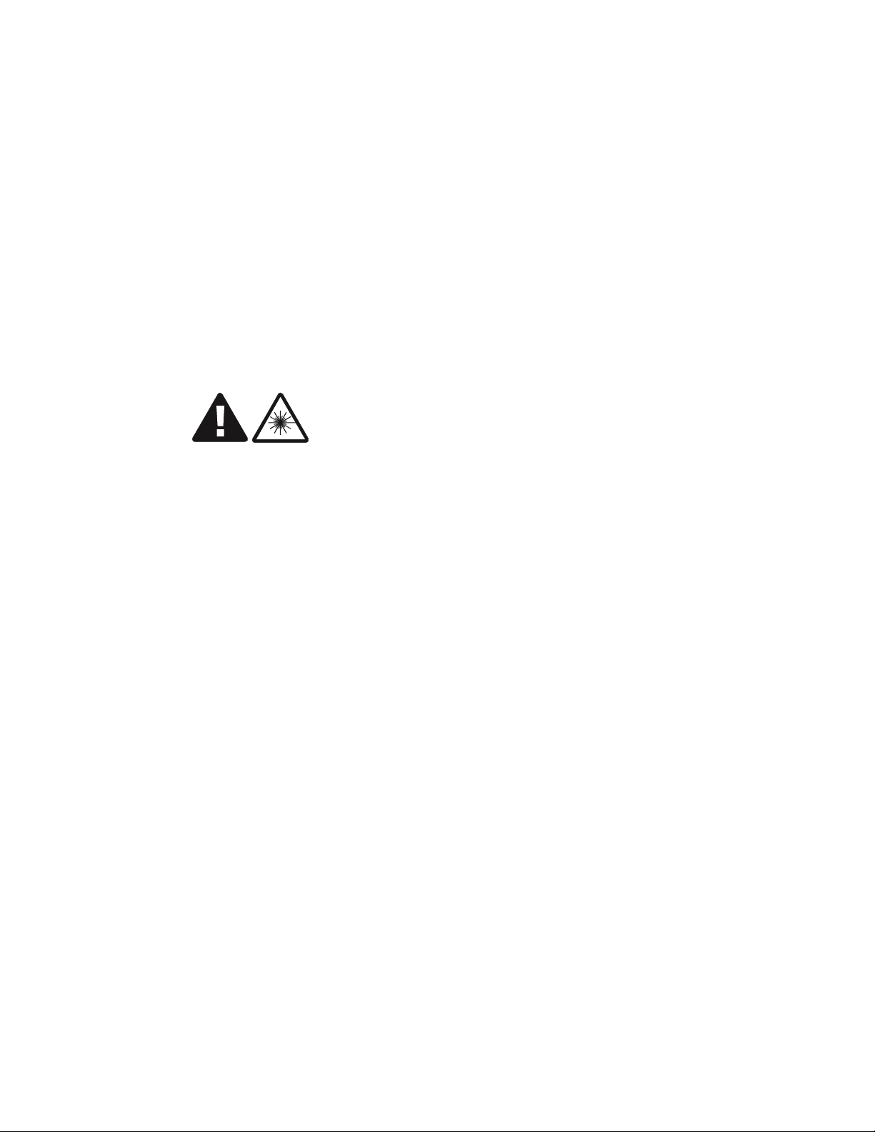
Product conformance statements United States
....................................................................................................................................................................................................................................
FDA/IEC optical transmitter product compliance
Alcatel-Lucent declares that 9412 eNodeB complies with the Food and Drug
Administration's Center for Devices and Radiological Health (FDA/CDRH) regulations
21 CFR 1040.10 and 1040.11. It is a Class I/1 laser optical fiber communication systems
"product" under the FDA.
This Product is designed to ensure that personnel operating t he product are not
endangered by laser radiation during normal operation and fault conditions. This product
does not present a risk of eye injury because it is fully enclosed and does not contain
embedded lasers greater than Class I/1 unless otherwise noted.
CAUTION
Laser hazard
Use of controls or adjustments or performance of procedures other t han those specified
herein may result in hazardous laser radiation exposure.
Do not view directly into the laser beam with optical instruments such as a fiber
microscope because viewing of laser emission in excess of Class 1 limits significantly
increases the risk of eye damage.
Never look into the end of an exposed fiber or an open connector as long as the optical
source is switched on.
Ensure that the optical source is switched off before disconnecting optical fiber
connectors.
Product safety conformance
This product is safety listed for the United States of America by a Nationally Recognized
Test Laboratory (NRTL) accredited by the US Department of Labor, Occupational Safety
and Health Administration (OSHA), such as UL, CSA, or others. The product bears t his
certification mark of this certification laboratory on its main nameplate label. Should the
local authority having jurisdiction (AHJ) require prior or additional verification of this
certification, a product certificate of compliance can be obtained from the specific
certification laboratory by the business/product unit Applicant for the product. “Any
modifications to this equipment are not permitted without review and written official
authorization from the specific certification laboratory. Unauthorized changes may violate
the product safety certification. Modifications or changes authorized by official CN/CNN
are assumed to have received prior approval from this Lab.
....................................................................................................................................................................................................................................
9412 eNB Compact
418-000-415
Issue 4.1 August 2011
Proprietary – Use pursuant to Company instruction
Alcatel-Lucent – Internal
C-11
Page 90

Product conformance statements United States
....................................................................................................................................................................................................................................
Baseband cabinet user space
The user space provided in the Baseband cabinet may be used for installing customer
specified equipment. However, the equipment must have been tested in the 9412 eNodeB
to FCC Part 15 (B) and met Class B requirements. Such an installation is subject to the
non-interference requirements of Section 15.5 and Part 2.953(d) of FCC rules.
Antenna exposure
Antenna installations for the9412 eNodeB shall be performed in accordance with all
applicable manufacturer's recommendations, and national laws and regulations. To ensure
correct antenna installation, the antenna installer shall perform all necessary calculations
and/or field measurements to evaluate compliance with applicable national laws or
regulations regarding exposure to electromagnetic fields. The supplier of radio
equipment, the supplier of antenna equipment and the integrator and builder of the site
must provide sufficient information so that the limits of the exclusion zones can be
determined. Any changes to the antenna or other equipment in the transmit path may
require re-evaluation of the exposures to electromagnetic fields.
Pursuant to 47 CFR Part 1, Subpart I, subject to the provisions of section 1.1307, all
installations must be evaluated for requirements contained in Table 1, “Limits for
maximum permissible exposure,” in section 1.1310.
Packaging collection and recovery requirements
Countries, states, localities, or other jurisdictions may require that systems be established
for the return and/or collection of packaging waste from the consumer, or other end user,
or from the waste stream. Additionally, reuse, recovery, and/or recycling targets for the
return and/or collection of the packaging waste may be established.
For more information regarding collection and recovery of packaging and packaging
waste within specific jurisdictions, please contact the Alcatel-Lucent Services Environmental Health and Safety organization. For installations not performed by
Alcatel-Lucent Technologies, please contact the Alcatel-Lucent Customer Support Center
at:
Technical Support Services, within the United States: +1 630 224 4762, prompt 2
....................................................................................................................................................................................................................................
C-12
Proprietary – Use pursuant to Company instruction
Alcatel-Lucent – Internal
9412 eNB Compact
418-000-415
Issue 4.1 August 2011
Page 91

Product conformance statements United States
....................................................................................................................................................................................................................................
Material content compliance
The following notification applies to Alcatel-Lucent products distributed for sale, resale
or use.
This product, part, or both may include a lithium-manganese dioxide battery, which
contains very small amounts of a perchlorate substance. Special handling may apply.
For California:
Perchlorate Material - special handling may apply.
See http://www.dtsc.ca.gov/hazardouswaste/perchlorate/
....................................................................................................................................................................................................................................
9412 eNB Compact
418-000-415
Issue 4.1 August 2011
Proprietary – Use pursuant to Company instruction
Alcatel-Lucent – Internal
C-13
Page 92

Product conformance statements United States
....................................................................................................................................................................................................................................
....................................................................................................................................................................................................................................
C-14
Proprietary – Use pursuant to Company instruction
Alcatel-Lucent – Internal
9412 eNB Compact
418-000-415
Issue 4.1 August 2011
 Loading...