

Page 1
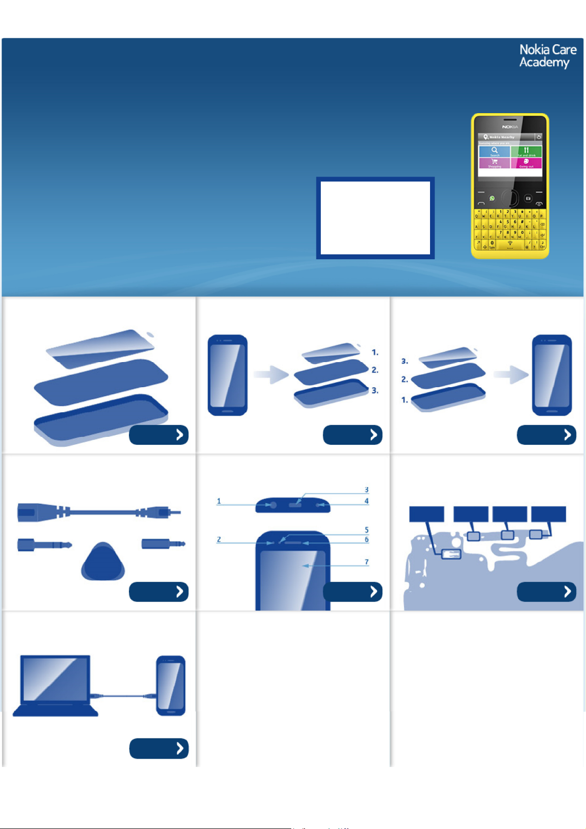
Service Manual for L1 and L2
z
z
z
z
z
Nokia Asha 210
RM-924, RM-928 (DS)
RM-925, RM-926, RM-929 (SS)
Key features
2.0 Mpix camera with innovative features
2.4" LCD display with 65k colors
QWERTY keyboard for fast and seamless messaging
Dual SIM functionality (RM-924, RM-928)
MicroSD card support up to 32 GB
Version 1.0
Check the repair
policy before
performing any
mechanical repair
on Service Level
1&2!
Exploded view Disassembly steps Assembly hints
More More More
Service devices Product controls and interfaces Solder components
Service concept
More More More
More
©2013 Nokia | Nokia Internal Use only | All Rights Reserved.
Page 2
Service Manual Level 1 and 2
Nokia Asha 210
RM-924, RM-925, RM-926, RM-928, RM-929
Version 1.0
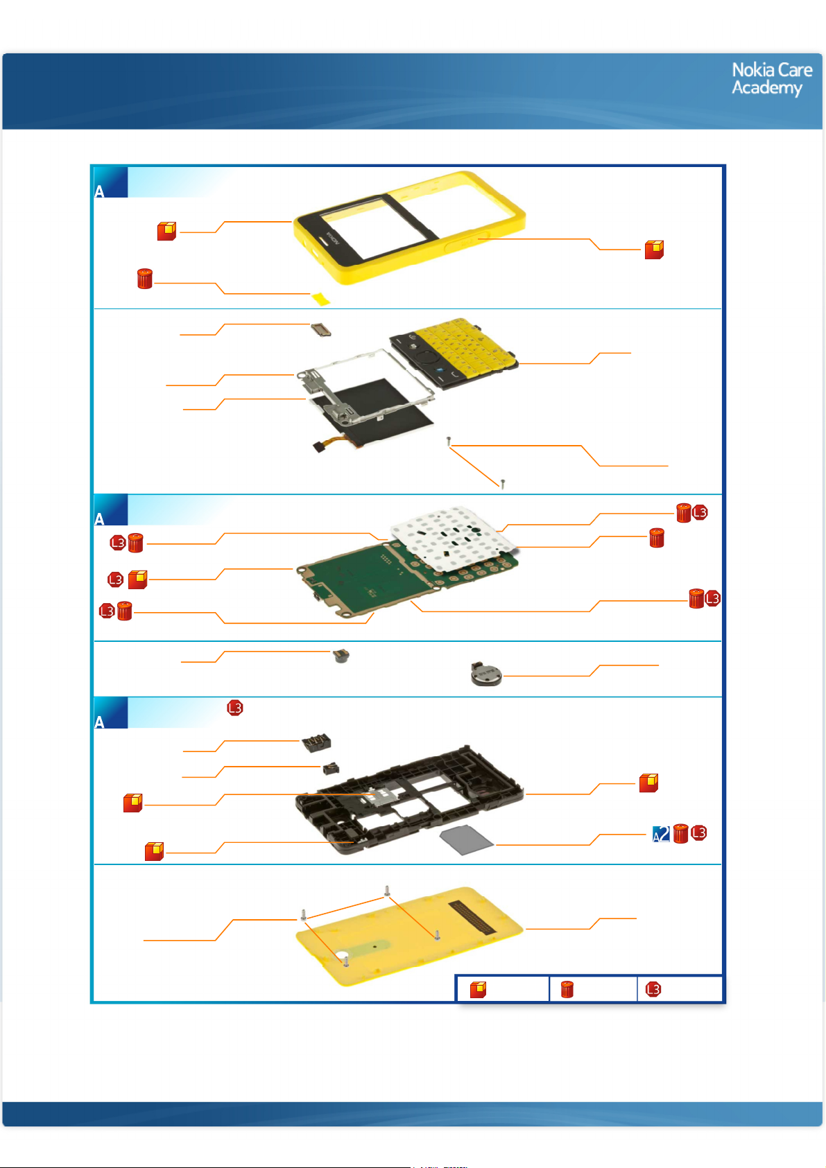
A-COVER ASSEMBLY
(I0001 - I0003)
1
A-COVER
I0001
EARPIECE MESH
I0003
EARPIECE
I0004
UI ASSEMBLY
I0007
DISPLAY
I0008
Exploded view
SIM DOOR
I0002
KEYMAT
I0005
SCREW TORX+
SIZE 4 RF 1.4 x 4.5
I0006
LIGHT SWAP PACKAGE
(I0009 - I0015)
2
BB SHIELDING LID
LIGHT SWAP PWB
WLAN SHIELDING LID
D-COVER ASSEMBLY
(I0017 - I0021 )
3
SIM LID ASSEMBLY
I0011
I0010
I0013
CAMERA
I0016
AV JACK
I0020
DC JACK
I0021
I0017
BT ANTENNA
I0018
FEM SHIELDING LID
I0012
DOMESHEET
I0009
BT_FEM SHIELDING LID
I0014
3 IN 1 SPEAKER
I0023
D-COVER
I0019
TYPE LABEL
I0015
SCREW TORX+
SIZE 6 RF 1.6 x 4.5
I0022
Only available
as assembly
©2013 Nokia | Nokia Internal Use only | All Rights Reserved.
B-COVER
I0024
Not reuseable
after removal
Repair/swap
only in level 3
Page 3
Service Manual Level 1 and 2
Nokia Asha 210
RM- 924, RM- 925, RM- 926, RM- 928, RM-929
Version 1.0
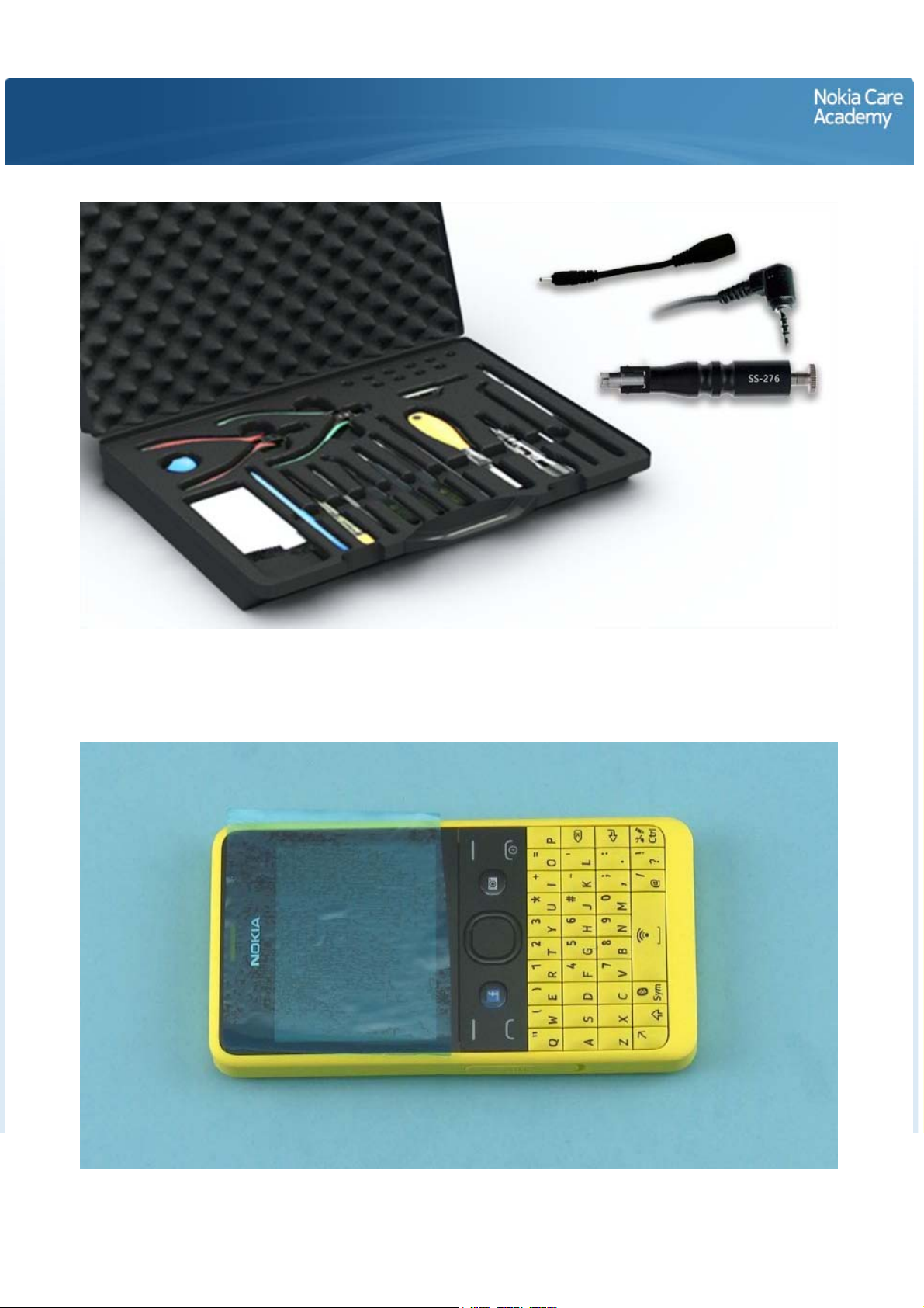
Disassembly steps
1) For disassembling you need the Nokia Standard toolkit version 2. You will also need a DC plug, an AV
plug and the camera removal tool SS-276. Note that the disassembly instructions are made with the dual
SIM variant (RM-924).
2) Protect the A-COVER with protective film.
Page 4
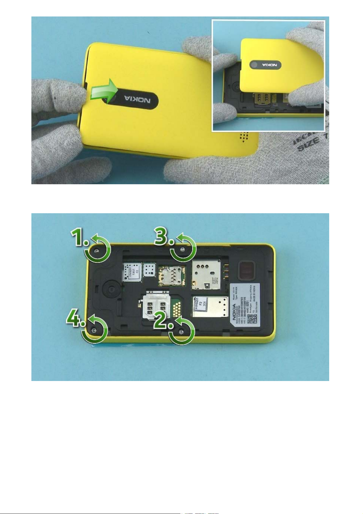
3) Use the finger groove to release the B-COVER
4) Unscrew the four Torx+ size 6 screws in the order shown.
Page 5
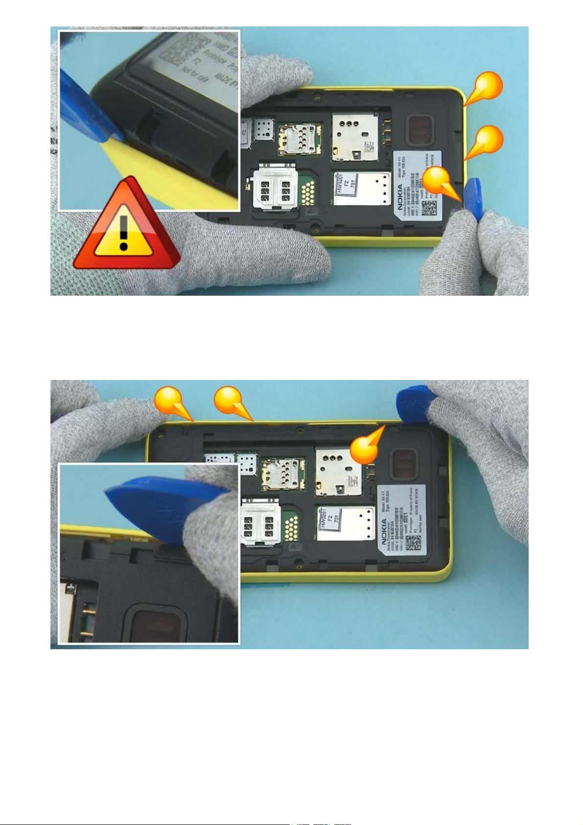
5) Start releasing the A-COVER from the bottom end of the device. Insert the SRT-6 between the ACOVER and D-COVER and release the three clips holding the A-COVER.
NOTE: SRT-6 must be inserted vertically to avoid damages in A-COVER.
6) Then release the shown clips on the SIM DOOR side. Pay attention not to damage the A-COVER.
Page 6
7) Release also the clips on the other side of the device with the SRT-6. Pay attention not to damage the
A-COVER.
8) Use the SRT-6 to release the two clips on the top end of the device. Pay attention not to damage the
A-COVER.
Page 7
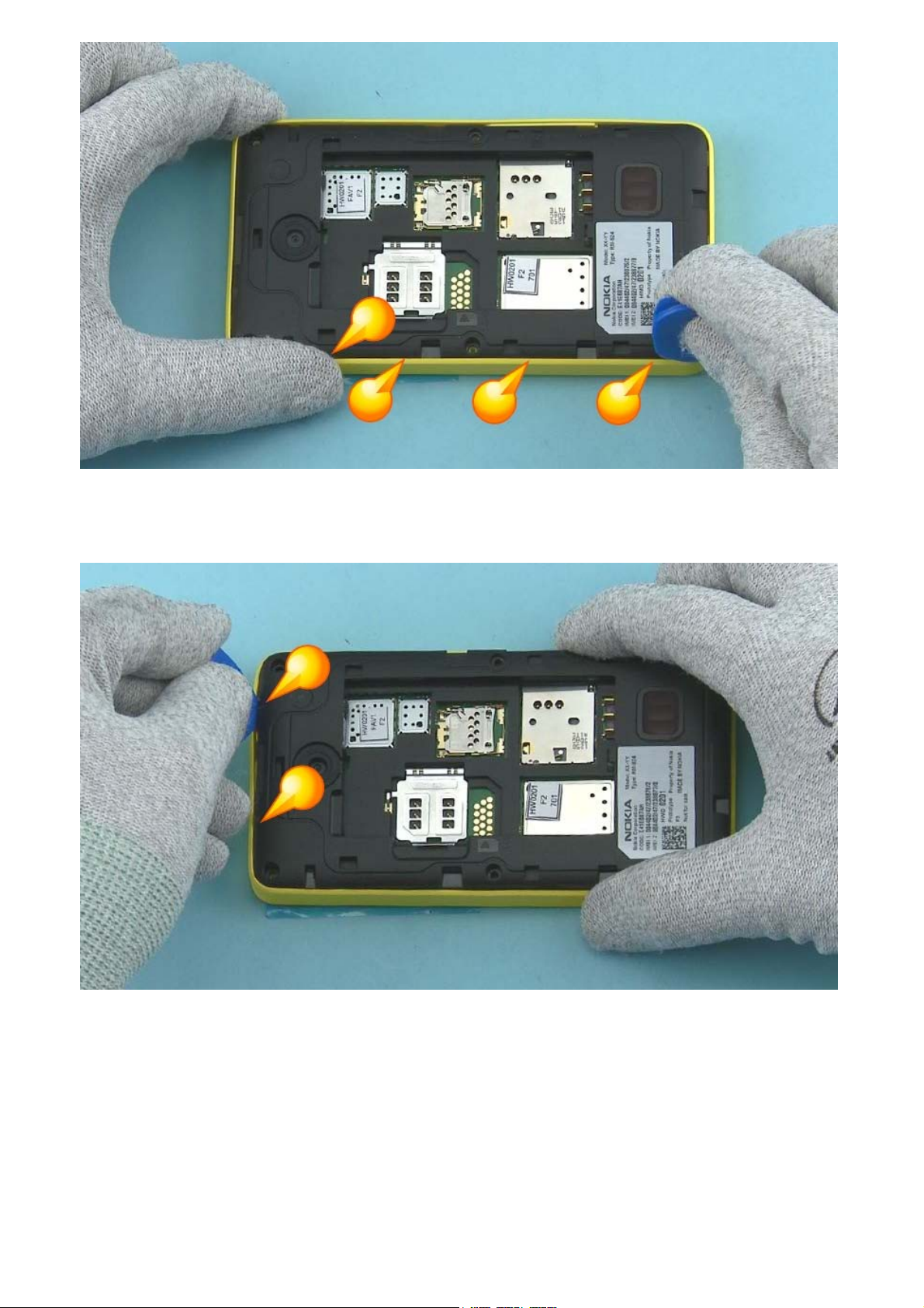
9) The A-COVER and the D-COVER with the ENGINE BOARD can now be separated.
10) Protect the DISPLAY with protective film.
Page 8
11) Protect also the other side of the A-COVER window.
12) Detach the KEYMAT by pushing it with fingers.
Page 9

13) Remove the KEYMAT.
14) Release the EARPIECE with the dental tool. Remove it with tweezers.
Be careful not to injure yourself with the sharp end of the dental tool.
Page 10

15) Use tweezers to remove the EARPIECE MESH. Do not use it again. Discard them.
16) Unscrew the two Torx+ size 4 screws in the order shown.
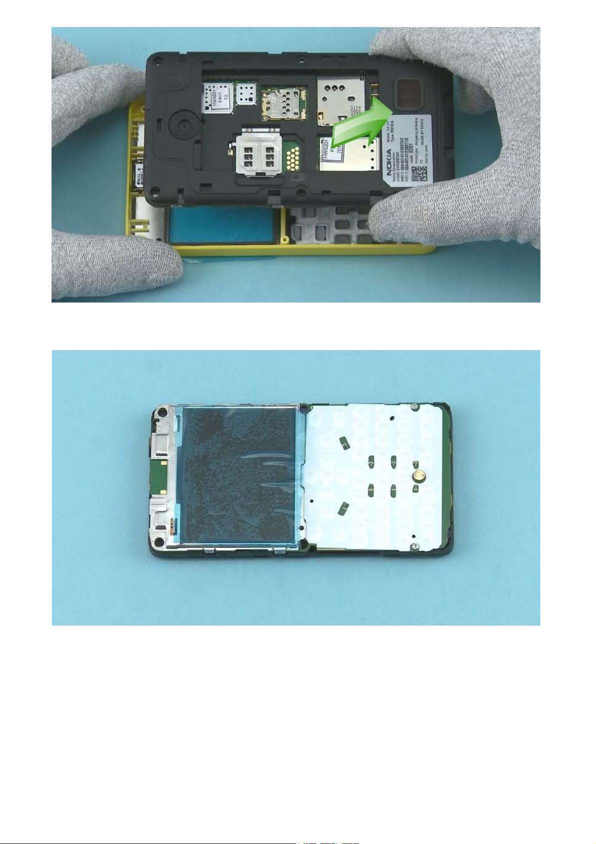
Page 11

17) Lever up the ENGINE BOARD with the SRT-6 from the shown place.
18) Lift up the ENGINE BOARD.
Page 12

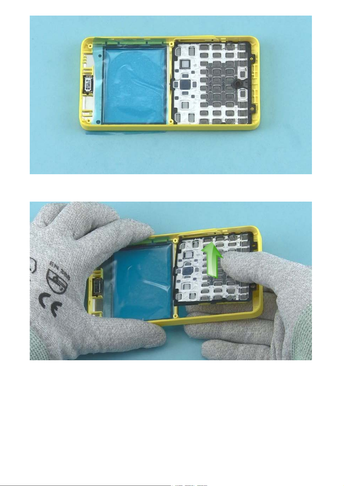
19) Disconnect the DISPLAY connector with the SS-93.
Be careful not to damage the connector or any components nearby.
20) Use the SS-93 to open the two clips holding the UI ASSEMBLY.
Page 13

21) Open also the two clips on the other side.
22) The UI ASSEMBLY and the DISPLAY can now be separated.
Page 14

23) Separate the DISPLAY from the UI ASSEMBLY.
24) Use tweezers to detach the DOMESHEET.
Page 15

25) The DOMESHEET can not be used again. Discard it.
26) Use the camera removal tool SS-276 to detach the CAMERA.
Page 16

27) Use the dental tool to lever out the 3 IN 1 SPEAKER.
Be careful not to make scratches onto the D-COVER.
28) Use tweezers to remove the 3 IN 1 SPEAKER.
Page 17

29) Use an AV plug to lift up and remove the AV JACK.
30) Use a DC plug to lift up and remove the DC JACK.
Page 18

31) The Nokia Asha 210 disassembly procedure is complete.
-END OF DISASSEMBLY-
©2013 Nokia | Nokia Internal Use only | All Rights Reserved.
Page 19

Service Manual Level 1 and 2
A
Nokia Asha 210
RM-924, RM-925, RM-926, RM-928, RM-929
Version 1.0
ssembly hints
1) Fasten the two TORX+ size 4 screws to the torque of 15 Ncm.
2) Fasten the four TORX+ size 6 screws to the torque of 17 Ncm.
-END OF ASSEMBLY HINTS-
©2013 Nokia | Nokia Internal Use only | All Rights Reserved.
Page 20

Service Manual Level 1 and 2
V
s
Nokia Asha 210
RM-924, RM-925, RM-926, RM-928, RM-929
ersion 1.0
Service device
CA-101 Service cable AC-11 Travel charger
AC-8C & CA-187C for China
SS-276 Camera removal tool Nokia Standard Toolkit (v2)
For more information, refer to the Service
Bulletin (SB-011) on Nokia Online. Supplier or
manufacturer contacts for tool re-order can be
found in “Recommended service equipment”
document on Nokia Online.
BL-4U Battery
©2013 Nokia | Nokia Internal Use only | All Rights Reserved.
Page 21

Service Manual Level 1 and 2
Nokia Asha 210
RM-924, RM-925, RM-926, RM-928, RM-929
Version 1.0
Product controls and interfaces
21
3
1 — Charger connector
2 — Headset connector (3.5mm )
3 —
Micro USB connector
4
4 — Earpiece
5 — Display
6 — Left selection key
5
9
6
7
8
10
11
12
13
7 — Facebook shortcut key
8 — Call key
9 — Scroll key
10 — Right selection key
11 — Camera key
12 — End/Power key
13 — Keyboard
14 — Camera
15 — Loudspeaker
16 — SIM card slot (SIM 2)
Only in dual SIM (RM-924, RM-928) variant!
17 — Antenna area
16
14
15
17
©2013 Nokia | Nokia Internal Use only | All Rights Reserved.
Page 22

Service Manual Level 1 and 2
Nokia Asha 210
RM-924, RM-925, RM-926, RM-928, RM-929
Version 1.0
Solder components
TOP
Engine board of RM-924 (DS / SC)
Keyboard
LED
V2422
V2421
Keyboard
LED
Keyboard
LED
V2424
V2423
Keyboard
LED
Keyboard
LED
V2426
V2425
Keyboard
LED
Keyboard
LED
V2428
V2427
Keyboard
LED
BOTTOM
Charger
fuse
F2051
F2050
USB
fuse
Note: F2050 only in
dual charging variants
(RM-928 / RM-929)
B2B
connector
X2500
G2200
Back-up
battery
E2750
Grounding
Spring
©2013 Nokia | Confidential | All Rights Reserved.
Page 23

Service Manual Level 1 and 2
Nokia Asha 210
RM-924, RM-925, RM-926, RM-928, RM-929
Version 1.0
Flashing concept
Service concept
Service
software
CA-101
FLS-5
BAT
Transceiver
©2013 Nokia | Nokia Internal Use only | All Rights Reserved.
Care Dummy Battery
with power supply
via Nokia charger or
product specific
battery
Page 24

Service Manual Level 1 and 2
V
V
y
Nokia Asha 210
RM-924, RM-925, RM-926, RM-928, RM-929
ersion 1.0
Version Date Description
1.0 25.04.2013 First published version
ersion histor
©2013 Nokia | Nokia Internal Use only | All Rights Reserved.
 Loading...