

Page 1

Programmes After Market Services
NPC-1 Series Transceivers
A ssembly & Disassembly
Instructions
Issue 1 10/01 ãNokia Corporation
Page 2

NPC-1
Assembly & Disassembly Instructions PAMS Technical Documentation
Table of Contents
Page No
Disassembling the NPC-1 Basic Transceiver ................................................................ 3
Assembling the NPC-1 Basic Transceiver..................................................................... 8
Page 2 ãNokia Corporation Issue 1 10/01
Page 3
NPC-1
c
PAMS Technical Documentation Assembly & Disassembly Instructions
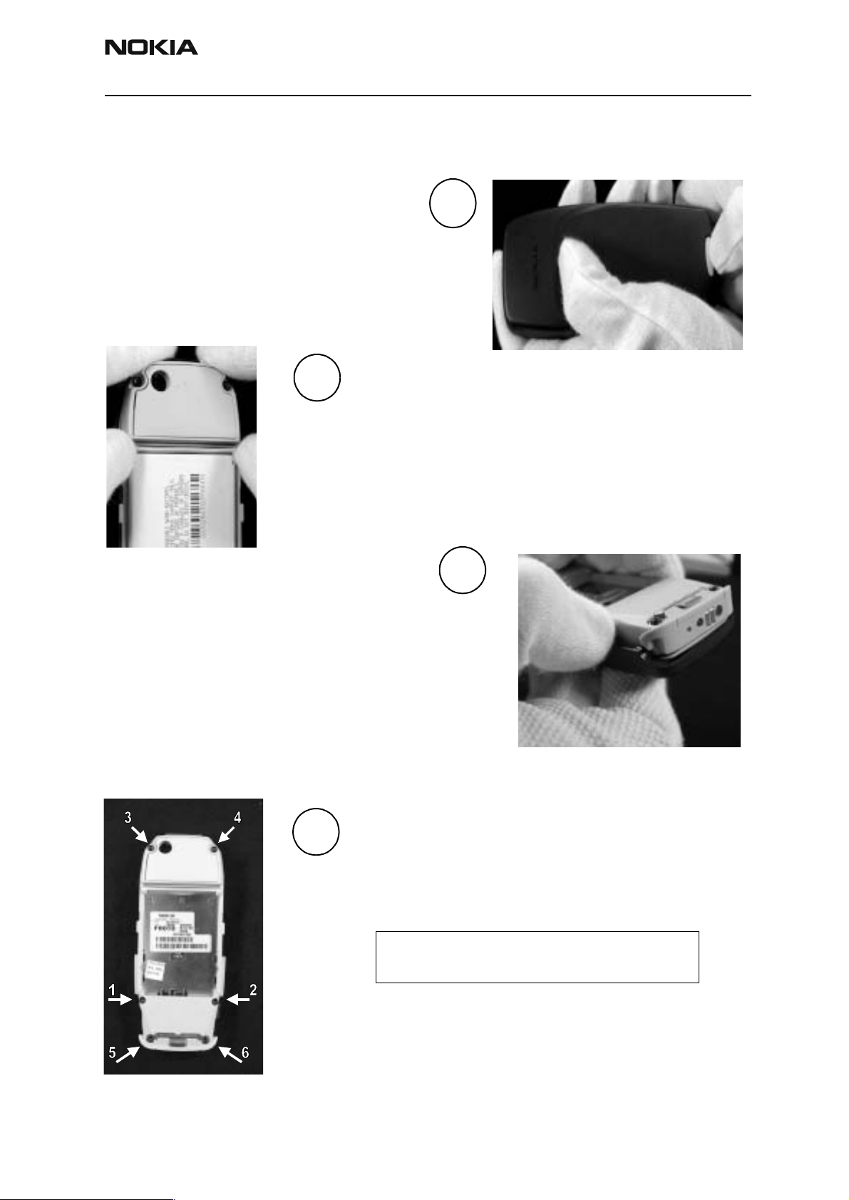
Disassembling the NPC-1 Basic Transceiver
Remove the back cover.
Step 1. Push down hard on the button.
Step 2. Slide the cover in the direction of the
arrow.
2.
Remove the battery.
Step 1. Place fingers on both ends of the battery lat
Step 2. Push the latch away from the battery.
The battery will “bounce off”.
Remove the front cover.
1.
3.
Step 1. Get a firm hold on the phone around the
accessory interfaces (in the D-cover).
Step 2. Hold the side of the front cover as indicated by
the arrow in the D-cover.
Step 3. Life the side up.
4.
Remove the PWB from the housing.
Remove 6 screws.
Note: The picture shows the assembly order.
Assembly is in the reverse order.
Issue 1 10/01 ãNokia Corporation Page 3
Page 4
NPC-1
Assembly & Disassembly Instructions PAMS Technical Documentation
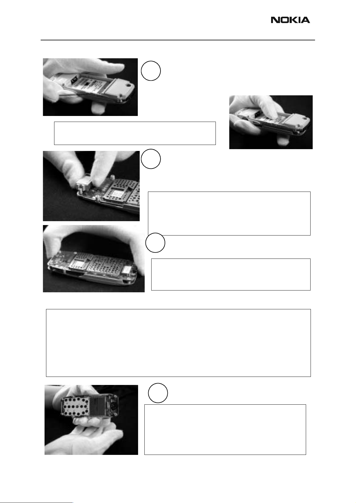
Disassemble C- and D-covers.
5.
Step 2. Lift the D-cover.
Step 1.
between the C- and D-covers’ snap feature.
Place a screwdriver with a chisel point
Note: The screwdriver must not hit the engine module’s
components during disassembly.
6.
Note: The use of gloves is mandatory while removing
the system connector, in order to prevent
fingerprints from appearing on the engine and
the springs. The springs may be damaged,
if touched.
Step 3. Remove the system connector.
The system connector assembly should
stay on the engine when the D-cover
is moved. It can be removed manually.
7.
Step 4. Remove the engine module.
Note: The use of gloves is mandatory while removing
the engine module, in order to prevent
fingerprints from appearing on the engine.
The engine module can be removed manually.
Note:
If the RF shield lid is removed, replace it with a new one as it is vital that the shield is
absolutely straight so that spurious radiation does not occur.
When removing the shield lid, please pay special attention to how it is done. The lid needs to
be removed extremely carefully, so as not to damage any other parts of the radio module.
Please use tweezers or a small screwdriver to remove the shield lid. Snap it open carefully.
Remove the LCD module.
8.
Note: If the LCD module is to be reused, the use of
gloves is mandatory to prevent fingerprints from
appearing on the domes and elastomer connector.
The domes and the elastomer connector may be
damaged, if touched.
Page 4 ãNokia Corporation Issue 1 10/01
Step 5. Lift it off the C-cover.
Page 5

NPC-1
PAMS Technical Documentation Assembly & Disassembly Instructions
9.
Step 4. Remove the speaker
assembly from the
C-cover.
Note: Handle with care, as the speaker and the
springs may be damaged, if touched.
10.
11.
Remove the battery latch.
Step 5. Get a firm hold on the middle of the
latch.
Step 6. Bend the latch and push it away
from the antenna.
Remove the antenna.
Step 7. Place a screwdriver with a flat
head between the antenna and the
D-cover.
Step 8. Lift the antenna.
Note: The antenna’s snap feature may be damaged
during disassembly. The broken snap will not
prevent the reuse of the ante nna.
Step 9. Remove the IR-window.
12.
You can remove the IR-window once the
antenna has been removed.
Remove the battery connector.
Step 10. Push the battery connector
13.
Note: Do not reuse the battery connector after
disassembly.
from the battery side to
remove it.
Issue 1 10/01 ãNokia Corporation Page 5
Page 6

NPC-1
Assembly & Disassembly Instructions PAMS Technical Documentation
Remove the release spring.
14.
Note: The broken heat staking features will not prevent replacing a new release spring
or buzzer onto the cover.
15.
Step 11. Use a flat-headed screwdriver to remove
the release spring from the D-cover.
The heat staking features will break during
disassembly.
Remove the vibra assembly.
Step 12. Lift the vibra assembly from its slot.
Use a screwdriver or your finger.
Remove the buzzer assembly.
Step 13. Place a screwdriver with a chisel-point
between the buzzer assembly and the
D-cover.
16.
Step 14. Lift the buzzer assembly.
The heat staking features will break during
disassembly.
Note: The broken heat staking features will not prevent the use of the buzzer.
Remove the metal deck.
Step 15. Release the four side locks with a
screwdriver.
17.
Step 16. Push the metal deck from the engine’s side.
Note: Do not reuse the metal deck after disassembly.
Page 6 ãNokia Corporation Issue 1 10/01
Page 7

NPC-1
PAMS Technical Documentation Assembly & Disassembly Instructions
The main parts of the phone disassembled.
Issue 1 10/01 ãNokia Corporation Page 7
Page 8

NPC-1
Assembly & Disassembly Instructions PAMS Technical Documentation
Assembling the NPC-1 Basic Transceive r
Assemble the D-cover assembly.
1.
2.
Step 4. Press the antenna into its place.
Note: Make sure that the antenna springs do not
get damaged or touched during assembly.
No fingerprints should get on the springs.
Step 1. Assemble the metal deck from the
back cover side by pressing it with your
fingers.
All six tabs should snap into the slots in the
D-cover.
Step 2. Place the IR-window onto the
D-cover before assembling the
antenna.
3.
The battery connector will be assembled onto the D-cover
with interference fixing.
Step 7. Place connector onto D-cover with tweezers.
Step 8. Push the connector into the D-cover slot with your fingers.
4.
Step 5. Place one end of the battery latch in to
the D-cover slot.
Step 6. Bend the latch and move the other
end into the D-cover slot.
Note: Make sure that the
battery connector is
below the D-cover edges after assembly. If the
buzzer- or vibra-assembly is in place, make
sure that the buzzer springs stay intact. The
may be damaged, if touched.
5.
Page 8 ãNokia Corporation Issue 1 10/01
Page 9

NPC-1
.
PAMS Technical Documentation Assembly & Disassembly Instructions
Step 9. Place the vibra assembly into its slot. Use
6.
Note: If the battery connector or the buzzer assembly is in
place, make sure that the battery connector springs
and the buzzer springs stay intact. the springs may be
damaged, if touched.
tweezers.
The vibra is assembled into the D-cover with
interference fixing.
Step 10. Place the buzzer assemble into its place.
Use tweezers.
The buzzer is assembled into the D-cover with
interference fixing.
Step 11. Place the release spring into the
8.
9.
D-cover slot.
The release spring is attached onto the
D-cover with screws that are used for
attaching the C- and D-covers. No heat
staking is needed.
Assemble the C-cover.
Step 1. Check the condition of the screw holes
If they are worn out, change the cover.
Step 2. Place the C-cover into a jig. Make sure
that the speaker with the speaker
gasket is in place.
7.
Note: Make sure that the speaker springs stay intact. They may be damaged, if touched.
Place the LCD-module onto the C-cover.
Note: the use of gloves or a vacuum picker
10.
Issue 1 10/01 ãNokia Corporation Page 9
is required, in order to prevent
fingerprints from appearing on the
LCD. Make sure that the elastomer
connector and domes stay intact
during assembly. Use compressed air
or a vacuum before assembling
the D-cover, in order to prevent
dust from getting onto the engine
layout.
Page 10

NPC-1
Assembly & Disassembly Instructions PAMS Technical Documentation
Note: The use of gloves is mandatory in
order to prevent fingerprints from
11.
Place the engine module on top of the
LCD-module.
appearing on the engine layout. Use
ionized air or a vacuum, before
assembling the D-cover, to remove
dust and other foreign particles
from the PWB assy.
Place the system connector on top of the
engine module.
12.
Note: The use of gloves is mandatory in orde r to
prevent fingerprints from appearing on
the engine layout and system connector
pads (charging pads). Make sure that the
system connector springs stay intact. The
springs may be damaged, if touched.
Assemble the D-cover assembly.
Step 1. Place the assembled D-cover on top of the
C-cover.
Step 2. Press the D-cover to snap the side locks.
14.
Assemble the keymat onto the front cover.
15.
Step 1. Place the keypad onto the front
cover before the cover is assembled
to the basic transceiver.
Step 2. Press the keypad into its place.
16.
13.
Assemble the screws.
Step 1. Fasten the 6 screws. The assembly
order is shown in the disassembly
section. The torque is 20 - 21 Ncm
350/RPM.
Assemble the front cover onto the basic
transceiver.
Step 1. First push the basic transceiver to the
front cover’s IR-window.
Step 2. Press the bottom part onto the front
part, so that it snaps onto the front
cover.
Page 10 ãNokia Corporation Issue 1 10/01
Page 11

NPC-1
PAMS Technical Documentation Assembly & Disassembly Instructions
Assemble the battery.
17.
Assemble the back cover.
Step 1. Place the back cover on the
phone.
Step 2. Slide the cover so that the spring snaps the
cover into place.
18.
Step 1. Push the battery connector interface.
Step 2. Press the battery down so that the
latch fits the battery in place.
Issue 1 10/01 ãNokia Corporation Page 11
Page 12

NPC-1
Assembly & Disassembly Instructions PAMS Technical Documentation
Page 12 ãNokia Corporation Issue 1 10/01
 Loading...