

Page 1

CCS Technical Documentation
NEM-2 Series Transceivers
Service Software Instructions
Issue 1 07/03 Copyright Nokia. All rights reserved.
Page 2

NEM-2 Company confidential
Service Software Instructions CCS Technical Documentation
[This page left intentionally blank]
Page 2 Copyright Nokia. All rights reserved. Issue 1 07/03
Page 3

Company confidential NEM-2
CCS Technical Documentation
Quick Guide for Phoenix Service SW Installation ........................................................ 3
Phoenix Installation Steps in Brief ..............................................................................3
Phoenix Service SW....................................................................................................... 4
Before Installation .......................................................................................................4
Startup ..........................................................................................................................5
Dongle Driver Installation and Version Check ...........................................................6
First Time Installation of Phoenix ...............................................................................7
Update Installation of Phoenix ..................................................................................10
How to Uninstall Phoenix ..........................................................................................11
Data Package for Phoenix (Product Specific).............................................................. 13
Before installation ......................................................................................................13
Installation of Phoenix Data Package (Product Specific) ..........................................14
How to Uninstall Data Package .................................................................................17
How to Manage Connections .....................................................................................18
Manual Settings....................................................................................................... 19
How to Update Flash Support Files for FPS-8* and FLS-4* ...................................... 21
Before Installation .....................................................................................................21
Installing the Flash Support Files ..............................................................................21
How to Update The FPS-8* Flash Prommer SW ......................................................24
FPS-8 Activation and Deactivation.............................................................................. 26
Activation ..................................................................................................................26
Deactivation ...............................................................................................................28
JBV-1 Docking Station SW ......................................................................................... 29
Before Installation .....................................................................................................29
Installing SW Needed for the JBV-1 SW Update .....................................................30
Updating the JBV-1 Docking Station Software .........................................................34
FPS-8/FLS-4S USB driver installation for NEM-X .................................................... 36
FPS-8C USB driver installation for NEM-X ............................................................... 38
Receiver tuning: Quick Guide for Tuning With Phoenix ............................................ 43
General remarks .........................................................................................................43
Service Tool Concept for RF Tuning Operations ........................................................ 44
Automated RF tunings for NEM-2 .............................................................................. 46
Autotuning .................................................................................................................46
Receiver Tuning: RX Channel Select Filter Calibration ...........................................50
RX Calibration ...........................................................................................................51
RX Band Filter Response Compensation ..................................................................54
Transmitter tuning........................................................................................................ 65
TX Power Level Tuning ............................................................................................65
TX I/Q Tuning ...........................................................................................................70
Service Tool Concept For Baseband Tuning Operations............................................. 73
Service Concept for NEM-2 Baseband tunings .........................................................74
Baseband Tuning operations........................................................................................ 75
Energy Management Tuning .....................................................................................75
LCD Contrast Tuning ................................................................................................77
Flashing Setup Instructions.......................................................................................... 79
POS (Point of Sales) Flash Concept via FLS-4 ......................................................79
Module Jig Concept ...................................................................................................80
Flash Concept via FPS-8 ...........................................................................................81
Issue 1 07/03 Copyright Nokia. All rights reserved.. Page 1
Page 4

NEM-2 Company confidential
CCS Technical Documentation
JBV-1 Service Concept ..............................................................................................82
Parallel Flash concept ................................................................................................83
Page 2 Copyright Nokia. All rights reserved. Issue 1 07/03
Page 5

Company confidential NEM-2
CCS Technical Documentation
Quick Guide for Phoenix Service SW Installation
Phoenix Installation Steps in Brief
DCT-4 generation Test and Service Software is called “Phoenix”
These are the basic steps to install the Phoenix
• Install the Phoenix Service SW
• Install the Data Package for Phoenix (product specific data and flash update package)
• Manage connection settings (depends on the tools you are using)
• Update FPS-8 SW (if you use FPS-8)
• Activate FPS-8
• Update JBV-1 Docking Station SW (only when needed)
The flash update files are delivered with then Phoenix Data Package so unless you want
to use certain version of this package, separate installation package is not needed anymore. If you want to use it, it should be installed after connection management, before
FPS-8 update.
Please refer to Service Manual and Technical Bulletins for more information concerning phone model specific service tools and equipment setup.
Issue 1 07/03 Copyright Nokia. All rights reserved.. Page 3
Page 6
NEM-2 Company confidential
Phoenix Service SW
Before Installation
• Check that a Dongle is attached to the parallel port of your computer.
• Download the installation package (e.g.
phoenix_service_sw_a3_03_83_005.exe) to your computer (e.g. C:\TEMP)
• Close all other programs
• Run the application file (e.g. phoenix_service_sw_a3_03_83_005.exe) and
follow instructions on the screen
• Administrator rights may be required to be able to install Phoenix depending
on the Operating System
• If the dongle driver is installed or updated, you need to reboot your PC before
the installation can continue.
CCS Technical Documentation
• If uninstalling or rebooting is needed at any point, you will be prompted by the
Install Shield program.
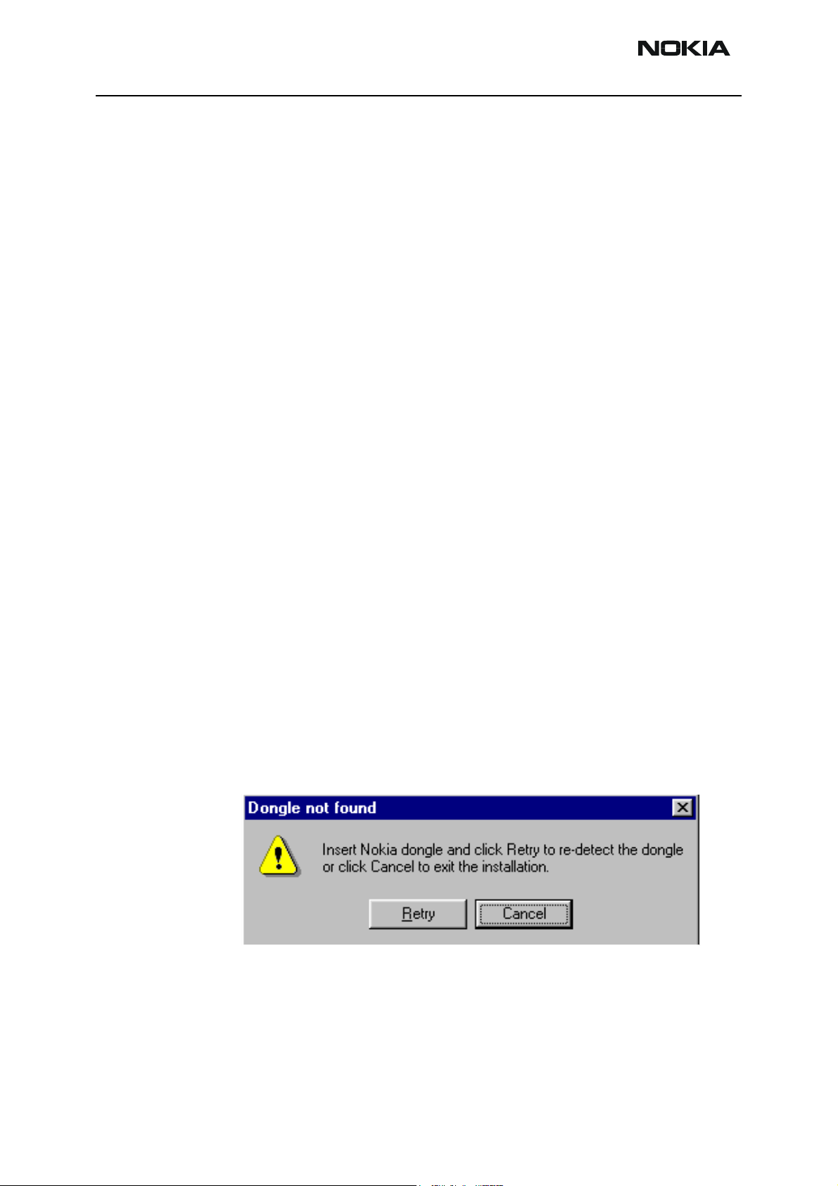
If at any point during installation you get this message, Dongle is not found and installation can´t continue.
Possible reasons may be defective or too old PKD-1Dongle (five digit serial number Dongle when used with FPS-8 Prommer) or that the FLS-4S POS Flash Dongle is defective or
power to it is not supplied by external charger.
Check the COM /parallel ports used first! After correcting the problem Installation can be
restarted.
Page 4 Copyright Nokia. All rights reserved. Issue 1 07/03
Page 7
Company confidential NEM-2
CCS Technical Documentation
Startup
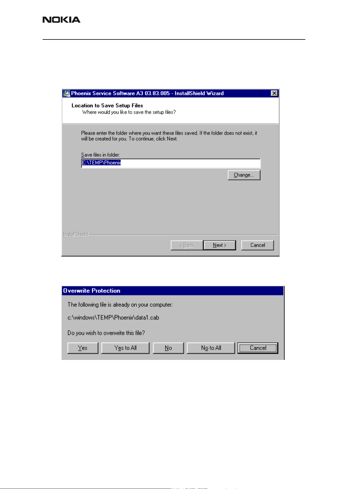
Run the phoenix_service_sw_a3_03_83_005.exe to start installation.
When you choose “Next” the files needed for installation will be extracted. Kindly wait.
If the setup files are already extracted (left in the file system from previous installation)
following dialog appears. Always click "Yes to All" to overwrite the existing setup files.
Issue 1 07/03 Copyright Nokia. All rights reserved.. Page 5
Page 8
NEM-2 Company confidential
Dongle Driver Installation and Version Check
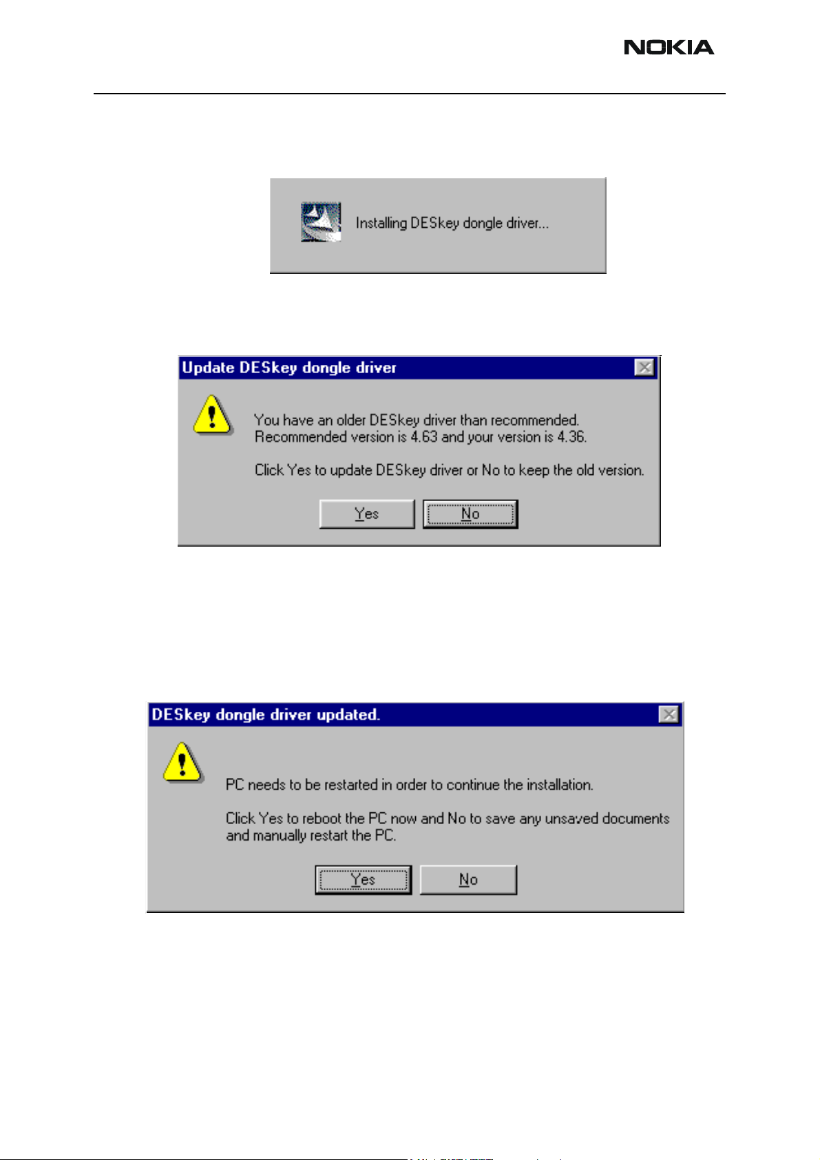
If there is no previously installed Dongle driver, installation will take place...
If the Dongle driver is installed and it is older than the latest supported version, the latest
version will be installed when you choose “Yes”. The latest version is always included in
the latest Phoenix installation package.
CCS Technical Documentation
PC needs to be rebooted before installation can continue. Click "Yes" to reboot the PC.
Setup is restarted automatically after reboot.
Page 6 Copyright Nokia. All rights reserved. Issue 1 07/03
Page 9
Company confidential NEM-2
CCS Technical Documentation
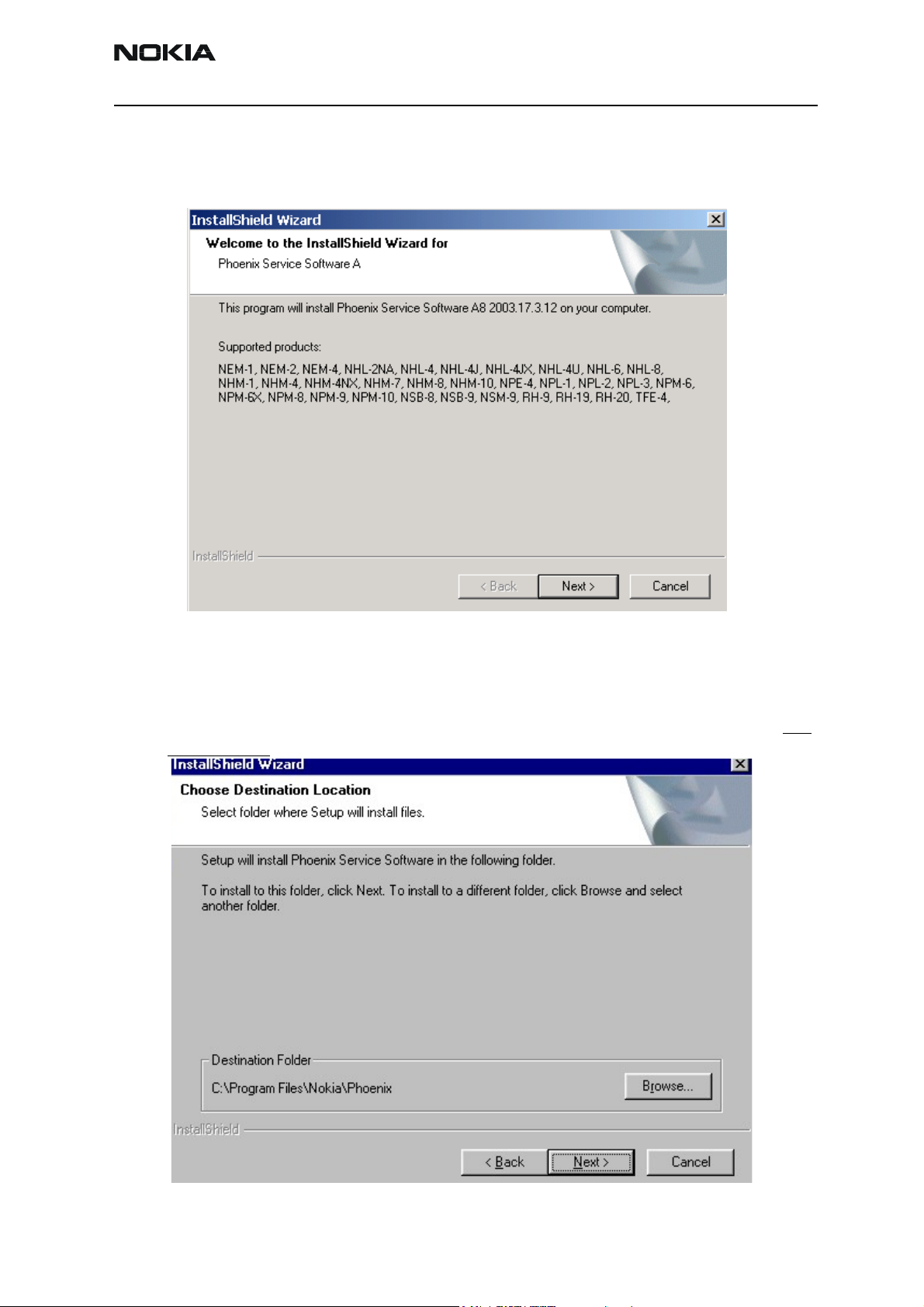
First Time Installation of Phoenix
After Dongle driver installation / update (if needed) installation continues from this step.
Click "Next" in Welcome dialog to continue.
Choose the destination folder, it is recommended to use the default folder C:\Program-
Files\Nokia\Phoenix.
Choose “Next” to continue. You may choose another location by selecting “Browse” (not
recommended)
Issue 1 07/03 Copyright Nokia. All rights reserved.. Page 7
Page 10
NEM-2 Company confidential
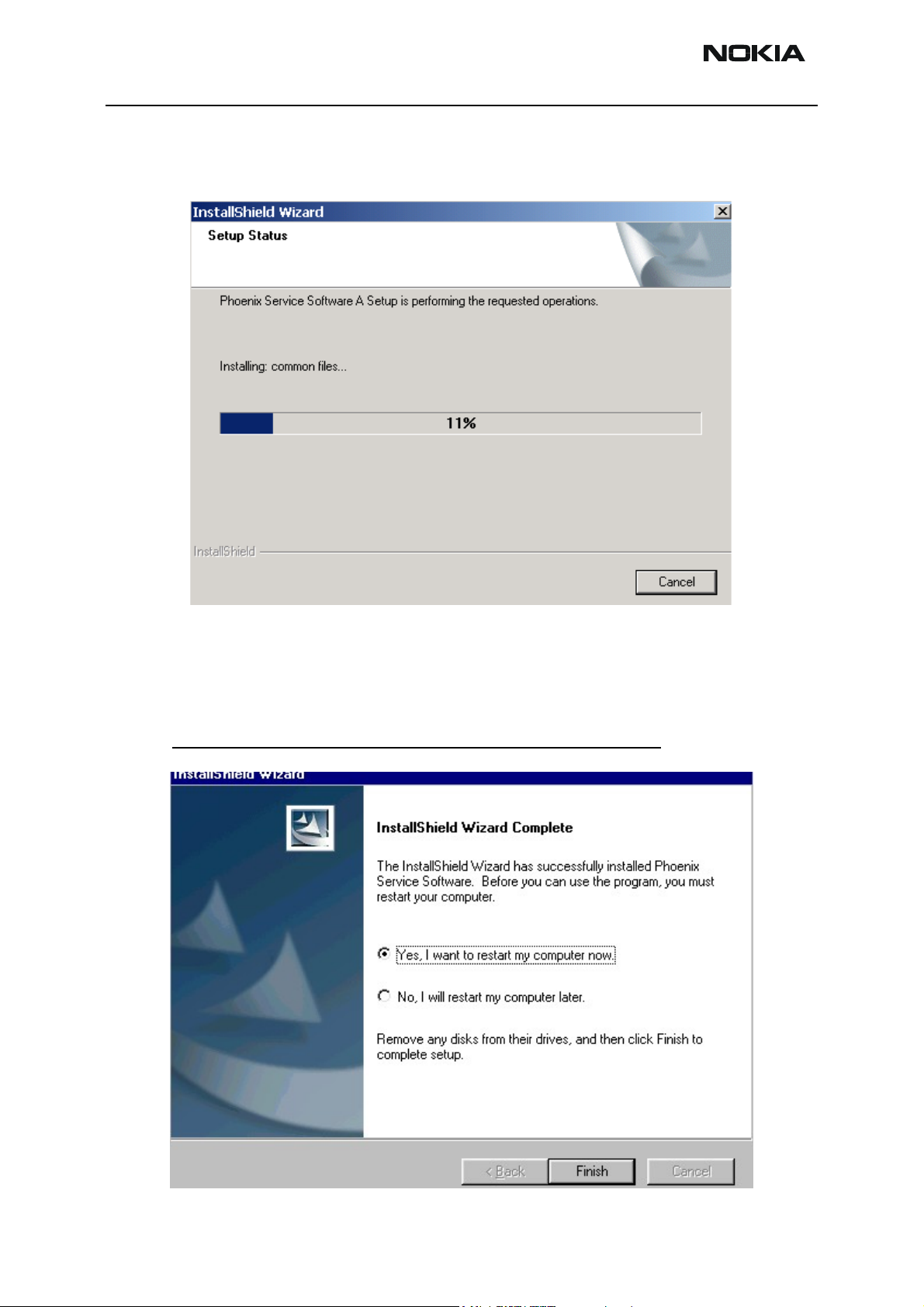
Setup copies the components, please wait.
Progress of the setup is shown. Please wait…
CCS Technical Documentation
If restarting of your computer is needed the Install Shield Wizard will tell you about it.
Select "Yes..." to reboot the PC immediatelly and "No..." to reboot the PC manually.
Note that Phoenix doesn't work, if components are not registered
continue.
. Click "Finish" to
Page 8 Copyright Nokia. All rights reserved. Issue 1 07/03
Page 11
Company confidential NEM-2
CCS Technical Documentation
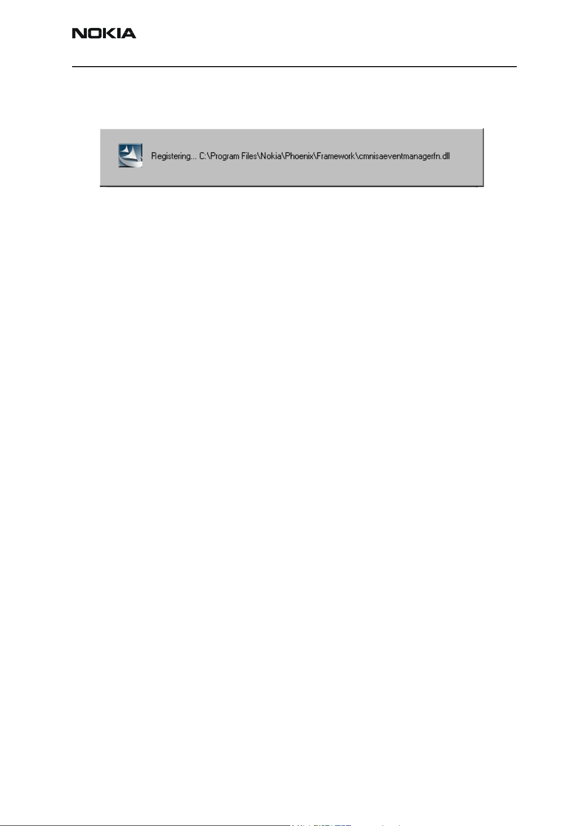
After the reboot components are registered and Phoenix is ready for use.
If reboot is not needed components are registered after copying them.
If restarting of your computer is not needed, Click "Finish" to exit the setup.
Phoenix is now ready for use.
Now the installation of Phoenix Service SW is ready and it can be used after:
• Installing Phone model specific Phone Data Package for Phoenix
• Configuring the connections
• Updating the Flash Update Package files used with FPS-8* and FLS-4* tools
Issue 1 07/03 Copyright Nokia. All rights reserved.. Page 9
Page 12
NEM-2 Company confidential
Update Installation of Phoenix
If you already have the Phoenix Service SW installed on your computer, sooner or later
there will be need to update it when new versions are released.
Please note that very often the Phoenix Service SW and the Phone Specific Data Package
for Phoenix come in pairs, meaning that certain version of Phoenix can only be used with
certain version of Data Package. Always use the latest available versions of both. Instructions can be found in phone model specific Technical Bulletins.
To update the Phoenix you need to take exactly the same steps as when installing it for
the first time.
• Download the installation package to your computer hard disk
• Close all other programs
• Run the application file (e.g. phoenix_service_sw_a3_03_83_005.exe)
CCS Technical Documentation
• Dongle driver version will be checked and if need be, updated
• After reboot installation starts automatically
• Newer version of Phoenix will be installed
When you update the Phoenix from old to new version (e.g. update from 3.83.005 to
3.83.005
5), the update will take place automatically without uninstallation
If you try update the Phoenix with the same version that you already have (e.g. 3.55 to
3.55) you are asked if you want to uninstall the version of Phoenix you have on your PC.
Answer “OK” to uninstall Phoenix, “Cancel” if you don’t want to uninstall.
If you try to install an older version (e.g. downgrade from 3.83.005 to 3.83.005) installation will be interrupted.
Always follow the instructions on the screen.
Page 10 Copyright Nokia. All rights reserved. Issue 1 07/03
Page 13
Company confidential NEM-2
CCS Technical Documentation
How to Uninstall Phoenix
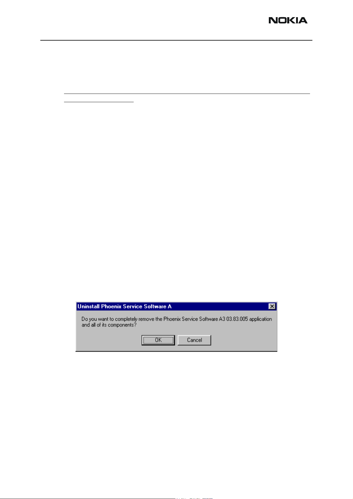
Uninstallation can be done manually from Windows Control Panel - Add / Remove Programs.
Choose “Phoenix Service Software” and click "Add/Remove".
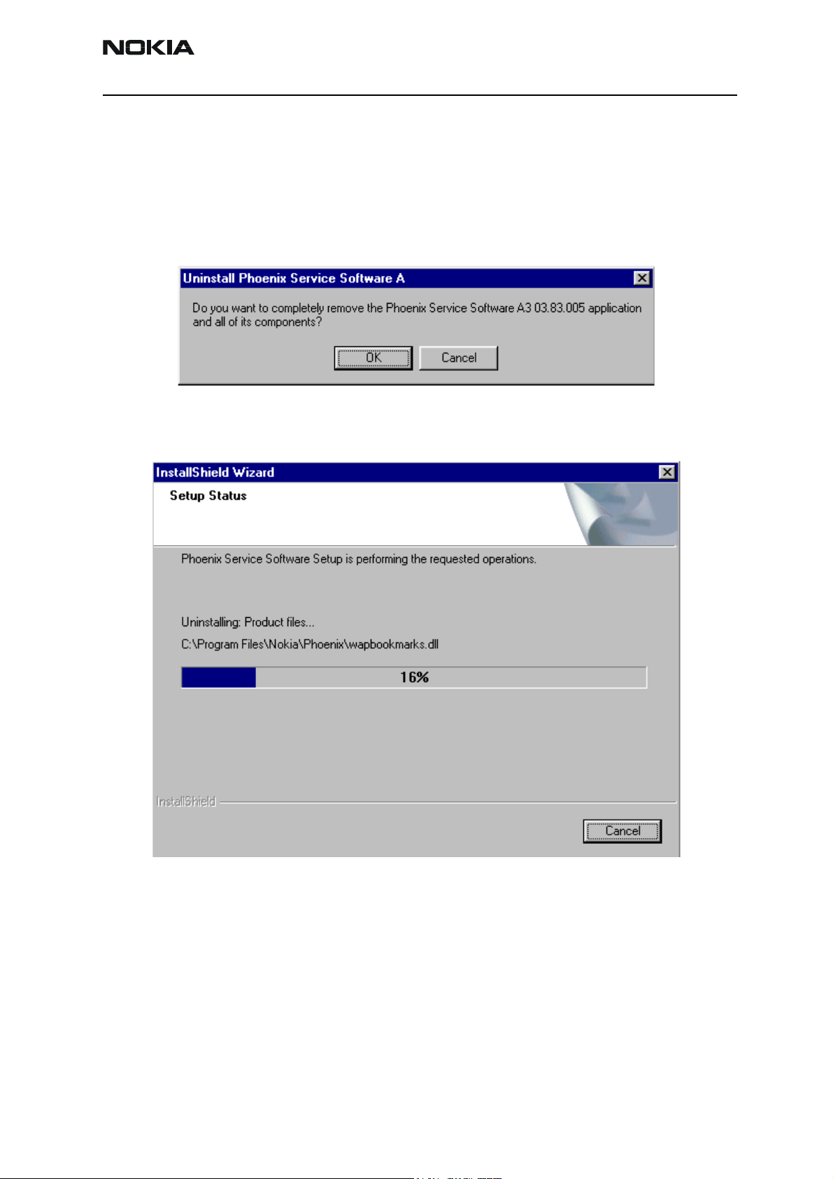
Choose “OK” to uninstall
Progress of the uninstallation is shown.
Issue 1 07/03 Copyright Nokia. All rights reserved.. Page 11
Page 14

NEM-2 Company confidential
You may have to reboot the PC after uninstallation.
CCS Technical Documentation
If restarting is not needed, the following dialog will appear:
Note! If you have different product packages installed, components are uninstalled only if they are not
included in other product packages.
Page 12 Copyright Nokia. All rights reserved. Issue 1 07/03
Page 15

Company confidential NEM-2
CCS Technical Documentation
Data Package for Phoenix (Product Specific)
Before installation
Product Data Package contains all product specific data to make the Phoenix Service
Software and tools usable with a certain phone model.
It also includes the latest version of flash update package for FLS-4* and FPS-8*
• Check that the Dongle is attached to the parallel port of your computer.
• Install Phoenix Service SW
• Download the installation package (e.g. nem-2_dp_1.00.exe) to your computer
(e.g. C:\TEMP)
• Close all other programs
• Run the application file (e.g.nem-2_dp_1.00.exe) and follow instructions on the
screen
If you already have the Phoenix Service SW installed on your computer, sooner or later
there will be need to update it when new versions are released.
Please note that very often the Phoenix Service SW and the Phone Specific Data Package
for Phoenix come in pairs, meaning that certain version of Phoenix can only be used with
certain version of Data Package. Always use the latest available versions of both. Instructions can be found in phone model specific Technical Bulletins.
Issue 1 07/03 Copyright Nokia. All rights reserved.. Page 13
Page 16

NEM-2 Company confidential
CCS Technical Documentation
Installation of Phoenix Data Package (Product Specific)
Run the
When you choose “Next” the files needed for installation will be extracted. Please wait
nem-2_dp_v_1.00.exe
to start installation.
Choose “Next” to continue.
Page 14 Copyright Nokia. All rights reserved. Issue 1 07/03
Page 17
Company confidential NEM-2
CCS Technical Documentation
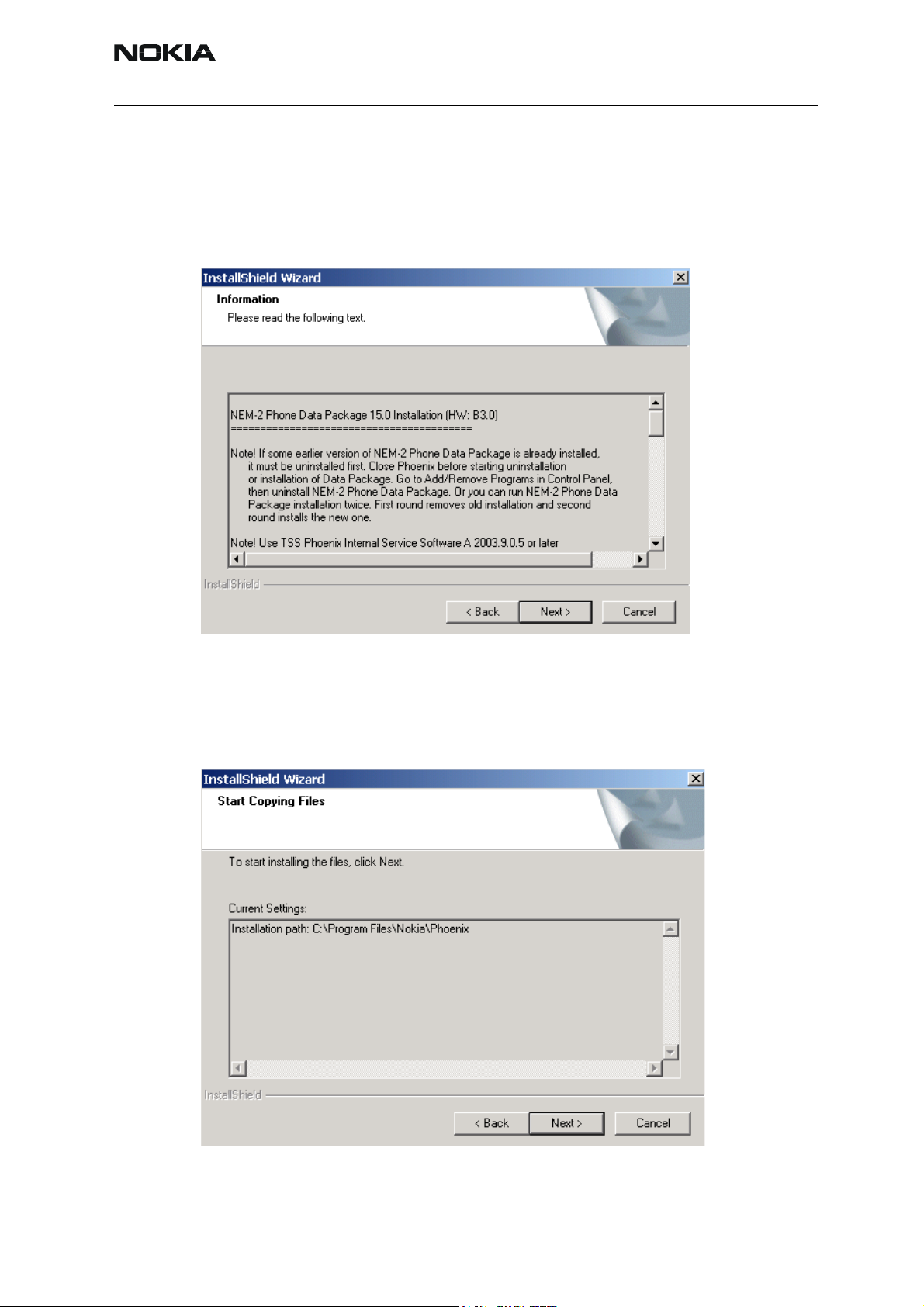
From this view you can see the contents of the Data Package.
Read the text carefully.
There should be information about the Phoenix version needed with this data package.
Choose “Next”.
Confirm location and choose “Next” to continue.
Install Shield checks where the Phoenix application is installed and the directory isshown. Choose “Next” to continue.
Issue 1 07/03 Copyright Nokia. All rights reserved.. Page 15
Page 18
NEM-2 Company confidential
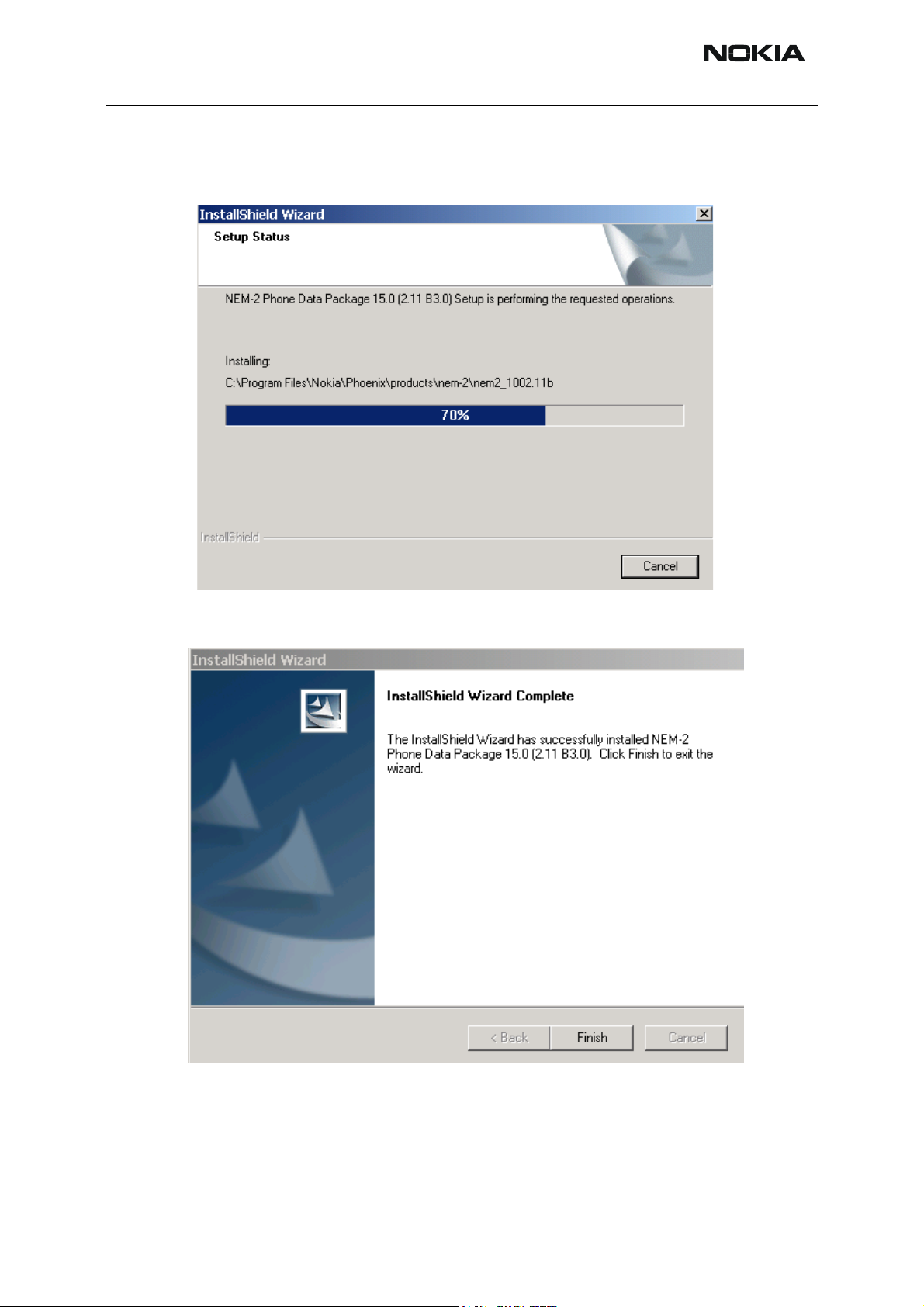
Phone model specific files will be installed... please wait.
CCS Technical Documentation
Choose “Finish” to complete installation.
You now have all phone model specific files installed in your Phoenix Service SW.
Page 16 Copyright Nokia. All rights reserved. Issue 1 07/03
Page 19
Company confidential NEM-2
CCS Technical Documentation
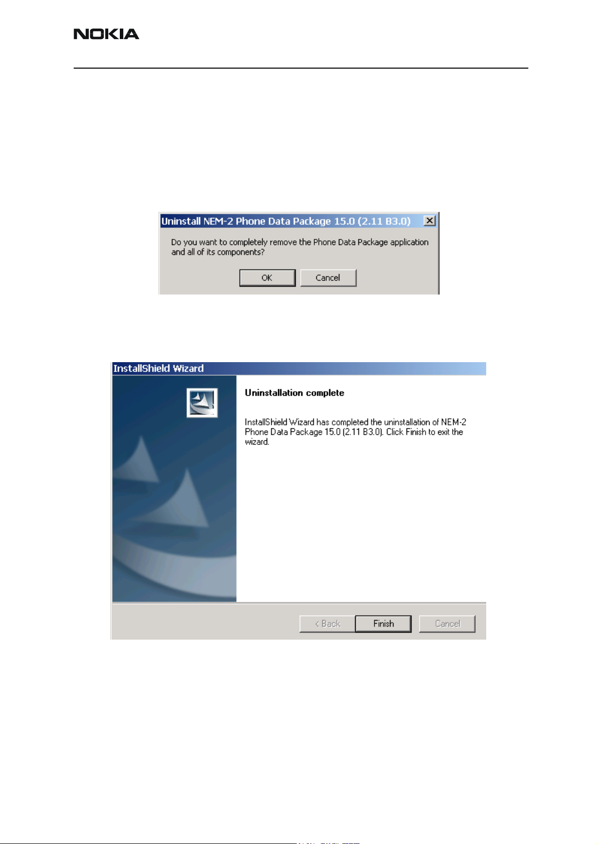
How to Uninstall Data Package
Uninstallation can also be done manually from Windows Control Panel / Add / Remove
Programs/ “NEM-2 Phone Data Package”.
If you try to install the same version of Phoenix Data Package that you already have, you
are asked if you want to uninstall the version you have on your PC. Answer “OK” to uninstall, “Cancel” if you don’t want to uninstall. Older versions of data packages do not need
to be uninstalled.
Once the previously installed Data package is uninstalled, choose “Finish”.
Run the
Issue 1 07/03 Copyright Nokia. All rights reserved.. Page 17
nem-2_dp_v_1.00.exe
again to continue installation from the beginning.
Page 20

NEM-2 Company confidential
How to Manage Connections
Start Phoenix Service SW and Login.
Choose “Manage Connections” From “File” – Menu
CCS Technical Documentation
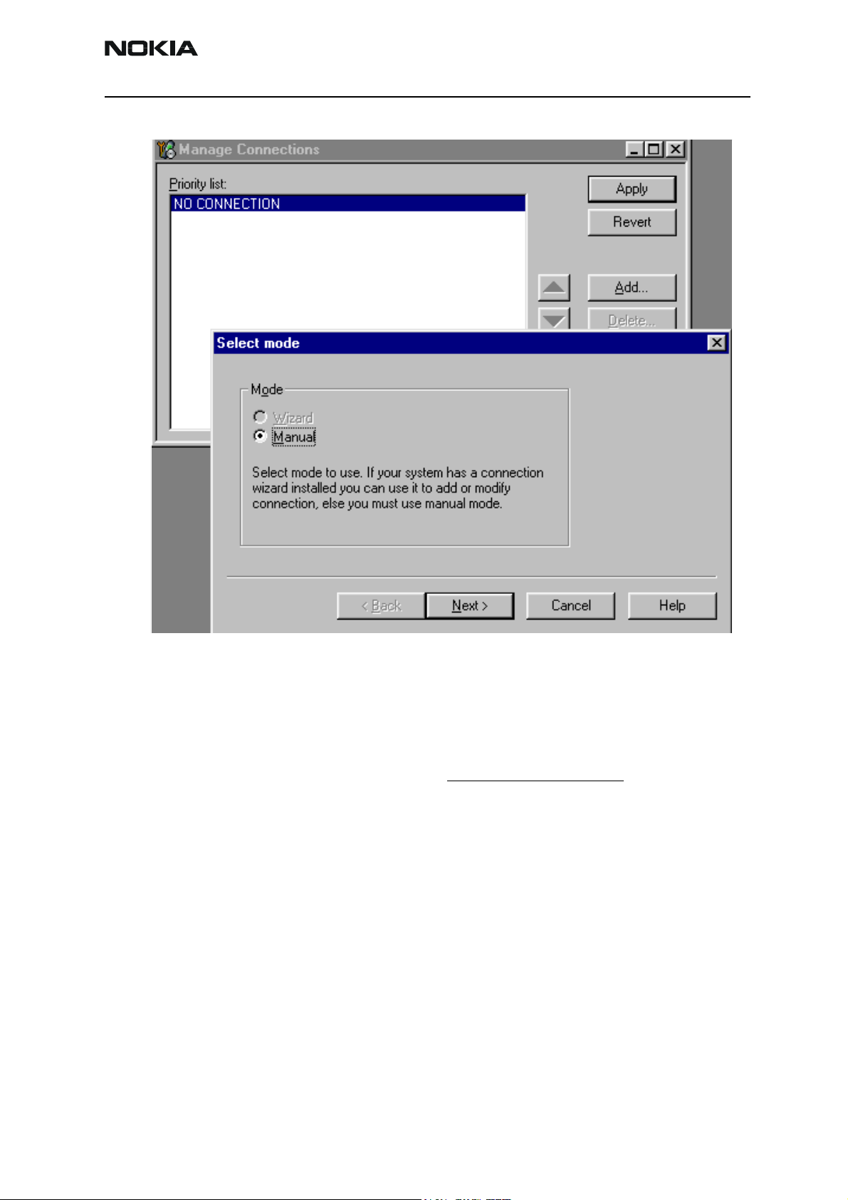
Existing connections can be selected, edited, deleted and new ones created by using this
dialog.
A connection can be created either manually or by using a Connection Wizard.
To add new connection, choose “Add” and select if you want to create it manually or by
using the Wizard.
Choose “Next” to continue.
Page 18 Copyright Nokia. All rights reserved. Issue 1 07/03
Page 21
Company confidential NEM-2
CCS Technical Documentation
In the next dialogs you will be asked to select some settings for the connection
Manual Settings
A) For FLS-4S POS Flash Device choose following connection settings
Media: FBUS
COM Port: Virtual COM Port used by FLS-4 Please check this always!
(To check please go to Windows / Control Panel / FLS Virtual Port / Configuration)
B) For FPS-8 Flash Prommer choose following connection settings:
Media: FPS-8
Port Num: COM Port where FPS-8 is connected
COMBOX_DEF_MEDIA: FBUS
Choose “Finish” to complete.
If you use the Wizard, connect the tools and a phone to your PC and the wizard will
automatically try to configure the correct connection.
Issue 1 07/03 Copyright Nokia. All rights reserved.. Page 19
Page 22
NEM-2 Company confidential
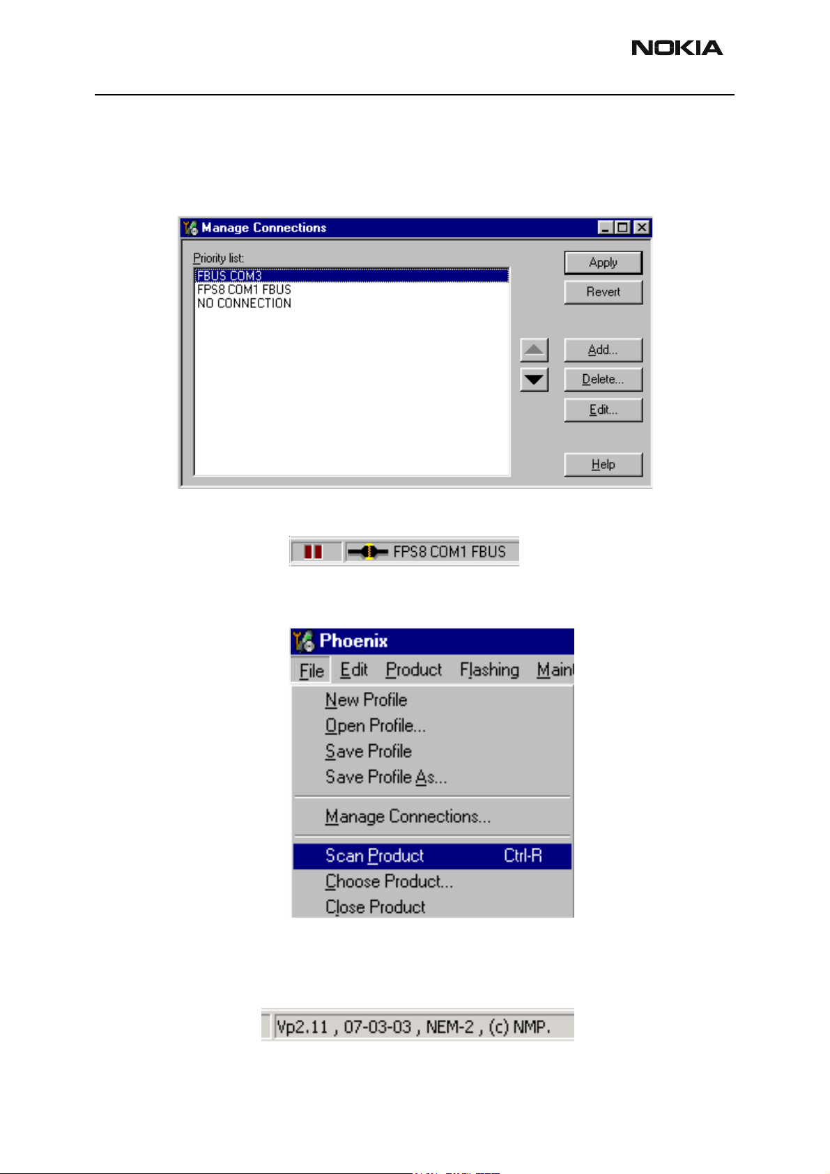
Activate the connection you want to use by clicking it and use up/down arrows to move
it on top of the list. Choose “Apply”.
The connection is now selected and can be used after closing the “Manage Connections”
window.
CCS Technical Documentation
Selected connection will be shown on the right hand bottom corner of the screen.
To use the selected connection, connect the phone to Phoenix with correct service tools,
make sure that it is switched on and select “Scan Product”.
When the Product is found, Phoenix will load product support and when everything is
ready, name of the loaded product support module and its version will be shown on the
bottom of the screen.
Page 20 Copyright Nokia. All rights reserved. Issue 1 07/03
Page 23

Company confidential NEM-2
CCS Technical Documentation
How to Update Flash Support Files for FPS-8* and FLS-4*
Before Installation
• Install Phoenix Service SW and Phoenix data package.
• Install the phone model Specific Datapackage for Phoenix
• The flash support files are delivered in the same installation package with
Phoenix data package.
• Normally it is enough to install the data package only before updating the FPS-
8.
• Separate installation package is for flash support files are available, and the
files can be updated according to this instruction.
Installing the Flash Support Files
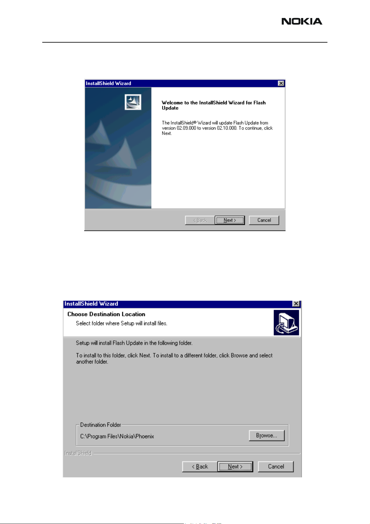
Start by double clicking eg. flash_update_02_10_00.exe. Installation begins.
If you already have the same Flash Update package files installed, you need to confirm if
you want them to be reinstalled.
Issue 1 07/03 Copyright Nokia. All rights reserved.. Page 21
Page 24
NEM-2 Company confidential
Choose “Next” to continue installation
CCS Technical Documentation
It is highly recommended to install the files to the default destination folder
Files\Nokia\Phoenix
Choose “Next” to continue. You may choose another location by selecting “Browse” (not
recommended).
.
C:\Program
Page 22 Copyright Nokia. All rights reserved. Issue 1 07/03
Page 25

Company confidential NEM-2
CCS Technical Documentation
Installation continues…
Choose “Finish” to complete procedure.
• FLS-4 can be used right after Flash Update Package is installed.
• FPS-8* must be updated by using Phoenix!
Issue 1 07/03 Copyright Nokia. All rights reserved.. Page 23
Page 26
NEM-2 Company confidential
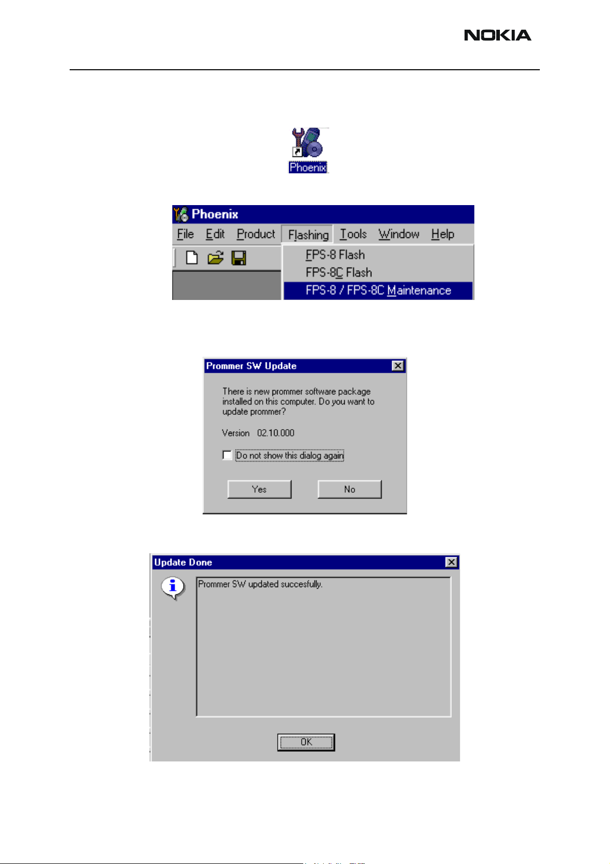
How to Update The FPS-8* Flash Prommer SW
Start Phoenix Service Software
Select”FPS-8 / FPS-8C maintenance” from”Flashing” menu.
When new FPS-8 flash update package is installed to computer you will be asked to
update the files to your FPS-8 Prommer. Select”Yes” to update files..
CCS Technical Documentation
0200
Update procedure takes a couple of minutes.
Page 24 Copyright Nokia. All rights reserved. Issue 1 07/03
Page 27

Company confidential NEM-2
CCS Technical Documentation
FPS-8 sw can also be updated by pressing”Update” button and selecting appropriate
fps8upd.ini file under
All files can be loaded separately to FPS-8. To do this, just press right mouse button in
Flash box files” window and select file type to be loaded.
C:\Program Files\Nokia\Phoenix
\Flash - directory
More information and help can be found from the “Help” dialog.
Issue 1 07/03 Copyright Nokia. All rights reserved.. Page 25
Page 28

NEM-2 Company confidential
FPS-8 Activation and Deactivation
• Before the FPS-8 can be successfully used for phone programming, it must be
first activated.
• If there is a need to send FPS-8 box to somewhere e.g. for repair, box must be
first deactivated.
Activation
Before FPS-8 can be successfully used for phone programming, it must be first activated.
Fill in first “FPS-8 activation request” sheet, in the FPS-8 sales package and follow the
instructions in the sheet.
When activation file is received (e.g. 00000.in), copy it to C:\Program-
Files\Nokia\Phoenix\BoxActivation - Directory on your computer
created when Phoenix is installed).
CCS Technical Documentation
(This directory is
Start Phoenix Service Software.
Select ”FPS-8 / FPS-8C maintenance” from ”Flashing” menu.
Select “Activate” from the “FPS8/8C Maintenance” – UI.
Page 26 Copyright Nokia. All rights reserved. Issue 1 07/03
Page 29
Company confidential NEM-2
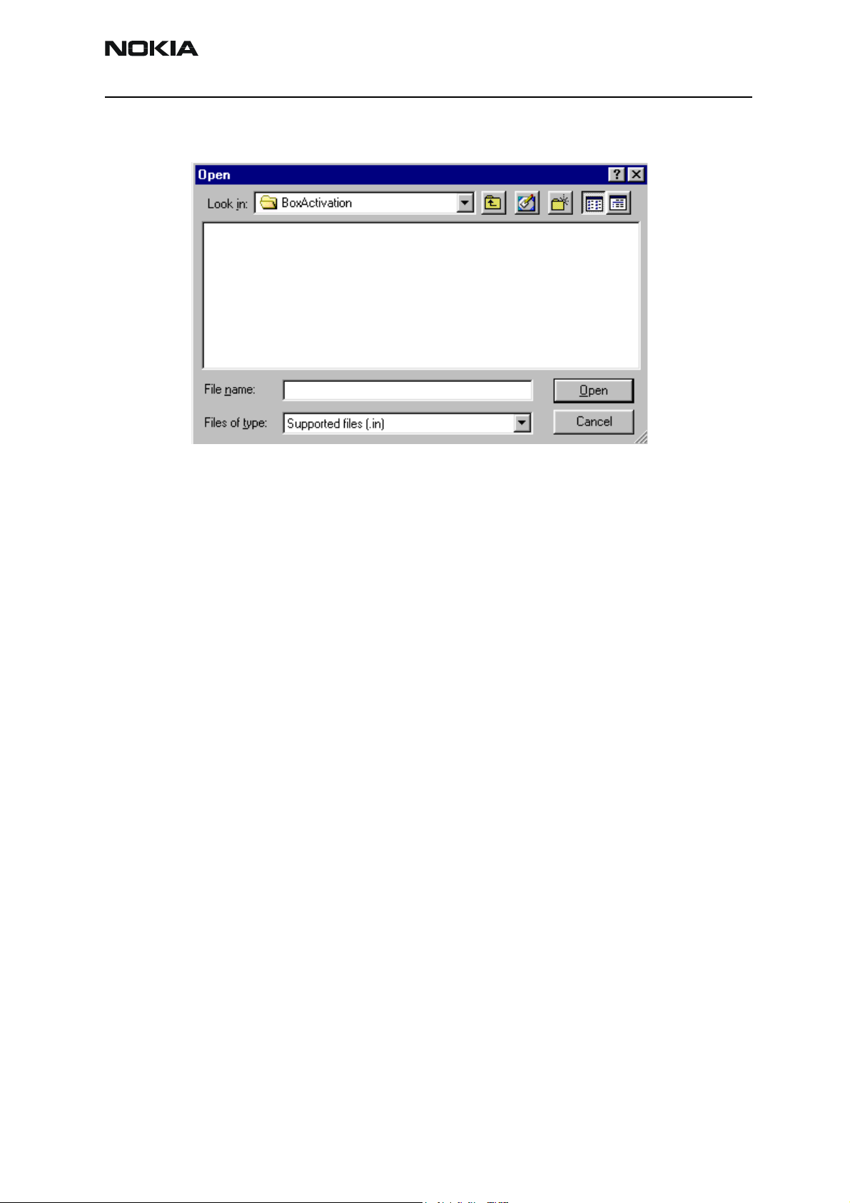
CCS Technical Documentation
The activation file you saved to C:\ProgramFiles\Nokia\Phoenix\BoxActivation - directory
will be shown (e.g. 00000.in), check that it is correct.
Box will be activated when you choose “Open”
Turn FPS-8 power off and on to complete activation
Issue 1 07/03 Copyright Nokia. All rights reserved.. Page 27
Page 30
NEM-2 Company confidential
Deactivation
Start Phoenix Service Software.
Select ”FPS-8 / FPS-8C maintenance” from ”Flashing” menu
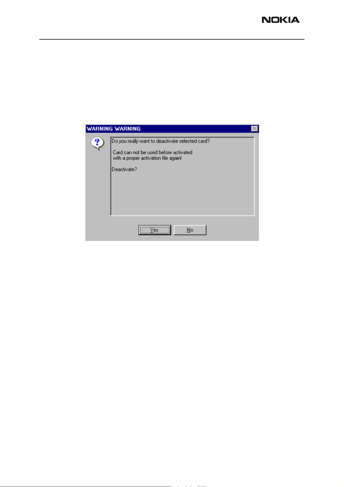
Select “Deactivate” from the “FPS8/8C Maintenance” – UI.
Confirm Deactivation by choosing “Yes”, Box will be deactivated.
CCS Technical Documentation
Turn FPS-8 power off and on to complete deactivation
Page 28 Copyright Nokia. All rights reserved. Issue 1 07/03
Page 31

Company confidential NEM-2
CCS Technical Documentation
JBV-1 Docking Station SW
The JBV-1 Docking Station is a common tool for all DCT-4 generation products. In order
to make the JBV-1 usable with different phone models, a phone specific Docking Station
Adapter is used for different service functions.
The JBV-1 Docking Station contains Software (Firmware) which can be updated.
You need the following equipment to be able to update JBV-1 software:
• PC with USB connection
• Operating System supporting USB (Not Win 95 or NT)
• USB Cable (Can be purchased from shops or suppliers providing PC hardware and
accessories)
• JBV-1 Docking Station
• External Power Supply 11-16V
Before Installation
• Download Jbv1_update.zip – file to your computer (e.g. C:\TEMP) from your download web site.
• Close all other programs
• Follow instructions on the screen
Issue 1 07/03 Copyright Nokia. All rights reserved.. Page 29
Page 32

NEM-2 Company confidential
Installing SW Needed for the JBV-1 SW Update
Note: DO NOT CONNECT THE USB CABLE / JBV-1 TO YOUR COMPUTER YET!
Run
Jbv1_update.zip
Files needed for JBV-1 Package setup Program will be extracted.
file and start SW Installation by double clicking
CCS Technical Documentation
Setup.exe
.
Installation begins, please read the information shown and Choose “Next” to continue.
Use suggested destination folder where JBV-1 SW Package will be installed and choose
Page 30 Copyright Nokia. All rights reserved. Issue 1 07/03
Page 33

Company confidential NEM-2
CCS Technical Documentation
“Next” to continue.
Select “Full” Installation and choose “Next” to continue
Program Folder will be created. Choose “Next” to continue, Software files will be
Issue 1 07/03 Copyright Nokia. All rights reserved.. Page 31
Page 34

NEM-2 Company confidential
installed.
CCS Technical Documentation
After successful installation, choose “Finish” to complete.
NOW YOU CAN CONNECT THE USB CABLE / JBV-1 TO YOUR COMPUTER!
Connect power to JBV-1 (11-16V DC) from external power supply, then connect USB
Page 32 Copyright Nokia. All rights reserved. Issue 1 07/03
Page 35

Company confidential NEM-2
CCS Technical Documentation
Cable between JBV-1 USB connector and PC.
Windows will detect connected USB cable and detect drivers for new HW.
Follow the instructions and allow Windows to search and install the best drivers available. After this procedure the actual JBV-1 SW update can begin.
Issue 1 07/03 Copyright Nokia. All rights reserved.. Page 33
Page 36

NEM-2 Company confidential
Updating the JBV-1 Docking Station Software
Go to folder C:\Program Files\Nokia\ JBV-1 SW Package\ FIRMWARE UPDATE and start
JBV-1 Update SW by double clicking fwup.exe.
JBV-1 Firmware update starts and shows current status of the JBV-1 connected.
If firmware version read from your JBV-1 is not the latest one available, it needs to be
updated by choosing “Update Firmware”.
CCS Technical Documentation
Choose file JBV1v11.CDE (example used here is for v 11) and “Open” to update your JBV-
1.
After Successful update, current JBV-1 status will be shown. You have now updated the
Page 34 Copyright Nokia. All rights reserved. Issue 1 07/03
Page 37

Company confidential NEM-2
CCS Technical Documentation
software of your JBV-1 docking station and it is ready for use.
Issue 1 07/03 Copyright Nokia. All rights reserved.. Page 35
Page 38

NEM-2 Company confidential
CCS Technical Documentation
FPS-8/FLS-4S USB driver installation for NEM-X
1. Connect the phone to the FPS8/FLS-4S and to the USB port and switch it on.
NOTICE: If you connect a NEM-X without a MMC card to the PC for the first time, a “USB
device“ is installed with an error. Ignore this error and press the “Finish” button to close
the window.
2. Start Phoenix and initiate the product scan.
3. Select Flashing -> FPS8 Flash. Now the correct Flash window should open. It has an
additional file selection for the ADSP file.
Page 36 Copyright Nokia. All rights reserved. Issue 1 07/03
Page 39

Company confidential NEM-2
CCS Technical Documentation
4. Press the button “Flash” to start flashing.
5. After a few seconds a windows "Found New Hardware" should popup. It installs the
first driver (Nokia ADSP device) automatically.
6. During flashing a second "Found New Hardware" should popup. It installs the second
USB driver (Nokia NEM-X) automatically.
7. Because the USB enumeration takes some time, this flashing sequence could end with
a ADSP timeout error. In this case restart flashing.
Issue 1 07/03 Copyright Nokia. All rights reserved.. Page 37
Page 40

NEM-2 Company confidential
CCS Technical Documentation
FPS-8C USB driver installation for NEM-X
If you will flash for the first time, you have to do the USB setup before. Else the USB
flashing won't be working!
NOTICE: To flash files, which added file sizes are together more than 7MB (e.g. NEM-1
V2.30 or higher), your FPS8C card must have 16MB RAM for successful flashing!
1. Start Phoenix V2003.11.1.9 or newer
2. Select the product: File -> Choose Product -> NEM-1 or NEM-2
3. Open Flashing -> FPS8C Flash (the window must include the additional ADSP file
selection)
4. Press "Init" button to bring all FPS8C cards in IDLE state
Page 38 Copyright Nokia. All rights reserved. Issue 1 07/03
Page 41
Company confidential NEM-2
CCS Technical Documentation
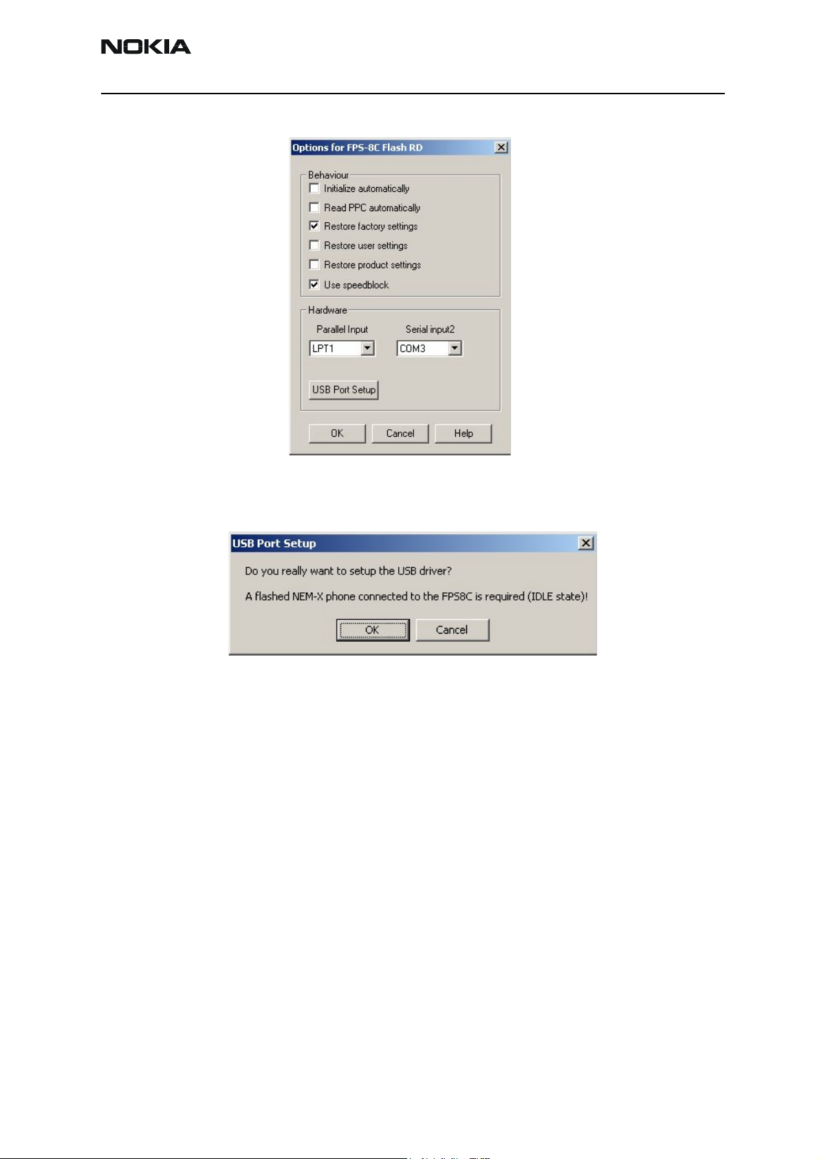
5. Start Usb Port Setup: Options -> "USB Port Setup"
6. The following window is shown:
7. The setup could be done with one phone, which is plugged from the first to the last
FPS8C port and USB port. Please mark the USB cable with e.g. it's number to make sure,
that it belongs always to the same FPS8C card! Press OK and follow the instructions.
Issue 1 07/03 Copyright Nokia. All rights reserved.. Page 39
Page 42

NEM-2 Company confidential
8. The following window is shown:
9. Depending on the used PC, the setup of one port could take 1 to 90 seconds. During
USB port setup several "Found New Hardware" should pop up and the driver will be
installed. If the port setup succeeded, the next port will be displayed. This sequence
repeats until all 8 ports are configured. If an error occured, the complete setup has to be
repeated.
CCS Technical Documentation
10. If all ports are completed, your sytem is prepared for the use of normally 8 USB
devices.
11. Now select the flash files and press “Start” to begin the flashing.
Page 40 Copyright Nokia. All rights reserved. Issue 1 07/03
Page 43

Company confidential NEM-2
CCS Technical Documentation
[This page left intentionally blank]
Issue 1 07/03 Copyright Nokia. All rights reserved.. Page 41
Page 44

NEM-2 Company confidential
CCS Technical Documentation
Page 42 Copyright Nokia. All rights reserved. Issue 1 07/03
Page 45

Company confidential NEM-2
CCS Technical Documentation
Receiver tuning: Quick Guide for Tuning With Phoenix
General remarks
RF tuning steps must be performed in the same order as shown in this document. The
order of the corresponding menu items in the Phoenix Service SW may be different.
If baseband tuning is needed, it must be completed before the RF tunings
Avoid unnecessary tuning – factory-tuning values are always the most accurate ones.
Screen shots described in this document may change as the service software is developed.
Kindly refer to the Phoenix help files, the phone model specific service manual and bulletins for help.
Note! All RF tunings for NEM-2 must take place inside JXS-2 RF Shield
box! Tuning in the MJ-6 module is not allowed!
Issue 1 07/03 Copyright Nokia. All rights reserved.. Page 43
Page 46

NEM-2 Company confidential
CCS Technical Documentation
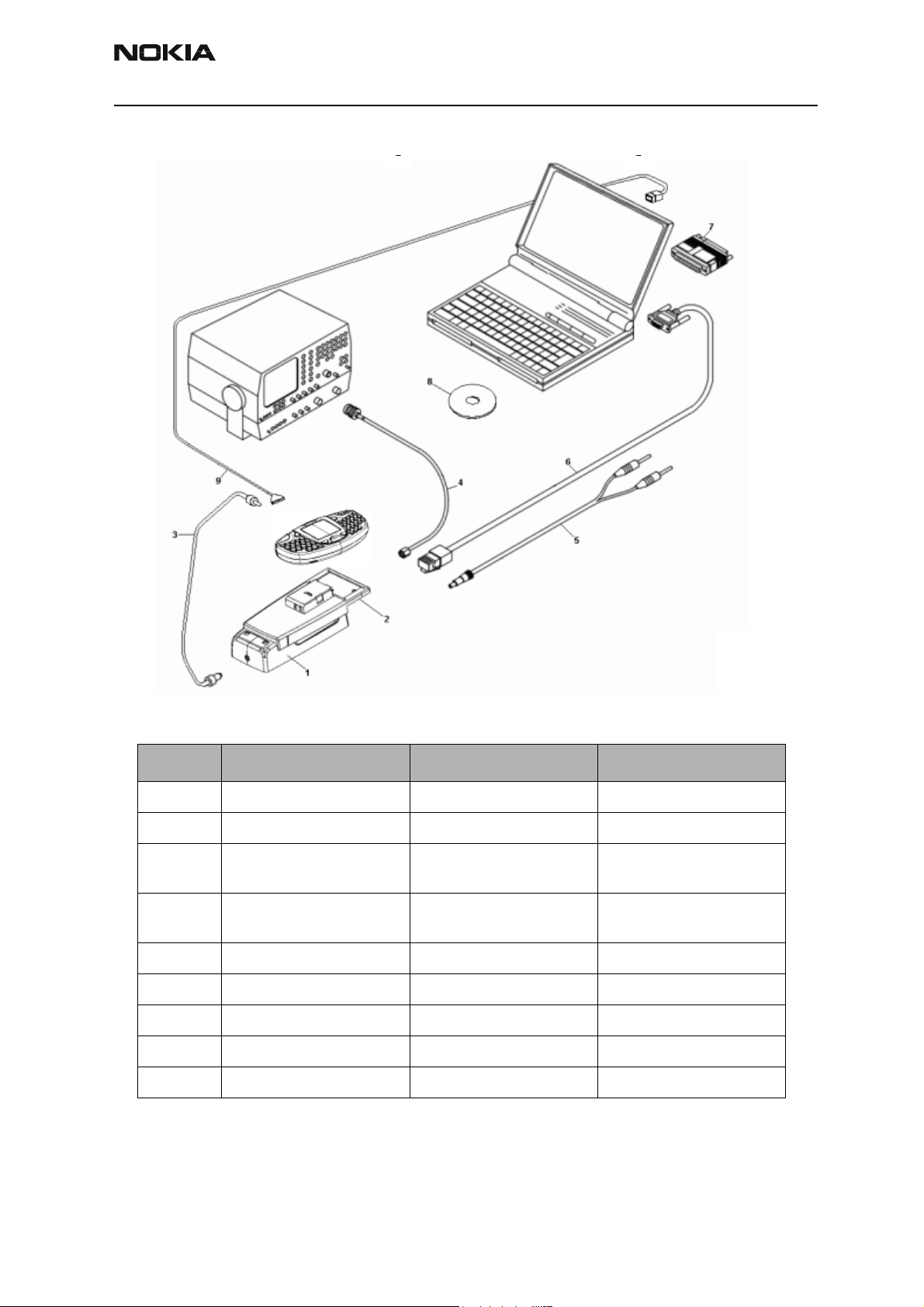
Service Tool Concept for RF Tuning Operations
• RF tuning setup must be carried out with JXS-2 and DA-1.
• Power to JBV-1 must be supplied from an external DC power supply, not
8 prommer
FPS-
• JBV-1 input voltage: Nominal input for RF tuning is +3.9 V DC
• Remember the cable attenuation when setting required RF levels
• DA-1 losses must be taken from the DA-1 label
Note! JBV-1 Docking Station stays outside the box. This is a Rhode&Schwartz CMU
Z11 shielded chamber modified to place the dockingadapter inside the box.
Figure 1: Service tools concept
Item: Type: Service accessory: Product code:
1 JBV-1 Docking station 0770298
Page 44 Copyright Nokia. All rights reserved. Issue 1 07/03
Page 47

Company confidential NEM-2
CCS Technical Documentation
Item: Type: Service accessory: Product code:
2 DA-1 Docking station adapter 0774288
3 JXS-2 Shield box 0770673
4 XRS-6 RF cable SMA to N-connec-
tor
5 PCS-1 Power cable for JBV-1 0730012
6SMA to SMA RF cable
6 PKD-1NS SW protection key
7 PKD-1CS SW protection key
9 Phoenix service SW
0730231
Issue 1 07/03 Copyright Nokia. All rights reserved.. Page 45
Page 48

NEM-2 Company confidential
Automated RF tunings for NEM-2
The recommended tuning of NEM-2 is autotuning.
Autotuning as well as all RF tunings must be performed via DA-1 inside JXS-2.
The losses for DA-1 RF coupler can be taken from the DA-1 label. Losses for the RF cables
must be added in the “set loss” function of Phoenix.
Autotuning
Autotune feature is designed to align product’s RF part easier and faster. By this autotune component product is tuned automatically. User needs to press only one button
(named ‘Tune’) and product’s RF is tuned and results are shown to the user. Component
controls all the needed RF equipment (RF generator and TX measuring device), except
power supply.
CCS Technical Documentation
Following diagram describes how the Autotune component is located in the TSS architecture:
Autotune UI
Autotune FN
Manual tune FNs GPIB FN
MTI
Phone
Autotune is a pair of two different components. First is User Interface and another is
FunctioNal. UI does not contain any functionality. MTI takes care of phonet messages.
GPIB Equipment
Page 46 Copyright Nokia. All rights reserved. Issue 1 07/03
Page 49

Company confidential NEM-2
CCS Technical Documentation
The Autotune component can be found under Tuning menu:
Environment:
Hardware requirements:
PC with Windows 98/2000/NT
Power supply
Product specific module jig
RF-splitter and -cables
RF equipment (only one of each is needed)
Tx:
Agilent E4406 (VSA series transmitter tester)
Agilent E4445 (PSA series transmitter tester)
Rohde&Schwarz, FSE-family of Signal Analyzers
Rohde&Schwarz, FSIQ-family of Signal Analyzers
Rx:
Agilent ESG family of RF Signal Generators
Rohde&Schwarz, SME-family of Signal Generators
or Rohde&Schwarz, CMU 200
Issue 1 07/03 Copyright Nokia. All rights reserved.. Page 47
Page 50

NEM-2 Company confidential
CCS Technical Documentation
GPIB addresses are not defined. Component finds the addresses and uses them automatically.
If several TX tuning devices are connected via GPIB bus, this component uses Agilent
(VSA or PSA). In RX side, Agilent has highest priority.
Protection
Components are protected by PKD-1CS, PKD-1NS, PKD-1 and PKD-1P dongles using
standard TSS protection procedure. Autotuning itself is possible with all those dongles
but with PKD-1P and PKD-1 dongles user is not able to set the loss.
Page 48 Copyright Nokia. All rights reserved. Issue 1 07/03
Page 51

Company confidential NEM-2
CCS Technical Documentation
Press “Tune” to start the tuning.
Issue 1 07/03 Copyright Nokia. All rights reserved.. Page 49
Page 52

NEM-2 Company confidential
CCS Technical Documentation
Receiver Tuning: RX Channel Select Filter Calibration
Extra equipment / external RF signal not needed.
Must be done before other RX calibrations.
This function is used to calibrate RX channel select filter in GSM Phones.
Rx Channel select filter is tuned only in one band = Single calibration for both bands.
Select Tuning => Rx Channel select filter calibration.
“Save to Phone “ is checked by default
Uncheck “Save to Phone “ if you don´t want the values to be saved to phone (eg testing)!
Press "Tune" to start the tuning
Tuning values must be between 0…31
If values shown are within limits, choose “Stop”. Close the “RX Channel Select Filter Calibration “– dialog to end tuning. Close the Rx Channel select filter calibration – dialog,
the values are saved to phone.
Page 50 Copyright Nokia. All rights reserved. Issue 1 07/03
Page 53

Company confidential NEM-2
CCS Technical Documentation
RX Calibration
RF generator needed.
This tuning performs RX Calibration.
Must be done separately on each band!
Calibration is automatically performed first at GSM850 and then at GSM1900 band. If
tuning is successfull, tuning continues in the next band.
AFC tuning is done while GSM850 band RX Calibration is performed.
Remember to take jig and cable attenuations into account!
Select Tuning => Rx calibration
Press “Start" to start tuning.
Issue 1 07/03 Copyright Nokia. All rights reserved.. Page 51
Page 54

NEM-2 Company confidential
Set RF generator to required GSM850 frequency => OK
Set RF generator to required frequency => OK
Tuning values and ADC readings are shown.
CCS Technical Documentation
Typical values and limits in (GSM850) RX Calibration:
GSM850 Typical value Low limit High limit
Afc value: -90 -350 350
Afc slope: 130 50 350
Rssi 0: 66 50 80
Rssi 1: 72 56 86
Rssi 2: 78 62 92
Rssi 3: 84 68 98
Rssi 4: 90 74 104
Rssi 5: 95 80 110
Rssi 6: 101 86 116
Rssi 7: 107 92 122
Rssi 8: 113 98 128
Rssi 9: 119 104 134
Rssi 10: 125 110 140
Rssi 11: 131 116 146
Rssi 12: 137 122 152
Rssi 13: 143 128 158
Rssi 14: 149 134 164
Set RFgenerator to required GSM1900 frequency => OK
Page 52 Copyright Nokia. All rights reserved. Issue 1 07/03
Page 55

Company confidential NEM-2
CCS Technical Documentation
Tuning values and ADC readings are shown.
Typical values and limits in (GSM1900) RX Calibration
GSM1900 Typical value Low limit High limit
Rssi 0: 63 47 77
Rssi 1: 69 53 83
Rssi 2: 75 59 89
Rssi 3: 81 65 95
Rssi 4: 87 71 101
Rssi 5: 94 77 107
Rssi 6: 100 83 113
Rssi 7: 106 89 119
Rssi 8: 112 95 125
Rssi 9: 118 101 131
Rssi 10: 124 107 137
Rssi 11: 130 113 143
Rssi 12: 136 119 149
Rssi 13: 142 125 155
Rssi 14: 148 131 161
Issue 1 07/03 Copyright Nokia. All rights reserved.. Page 53
Page 56

NEM-2 Company confidential
RX Band Filter Response Compensation
RF generator needed.
This operation must be done separately on each band!
Calibration is made automatically, starting with GSM850 and then with GSM1900..
NOTE! Remember to do RX calibration before doing Rx Band Filter Response Compensation!
Remember to take jig and cable attenuations into account!
Select Tuning => Rx band filter response compensation
CCS Technical Documentation
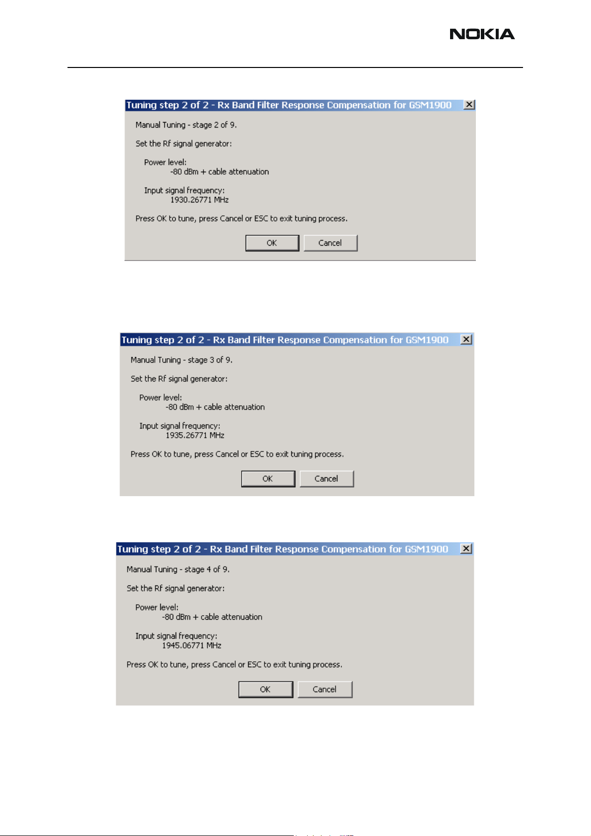
Select "Manual tuning" and press “Start” to start the tuning process.
You are asked to supply 9 different RF frequencies to the phone.
Page 54 Copyright Nokia. All rights reserved. Issue 1 07/03
Page 57

Company confidential NEM-2
CCS Technical Documentation
The tuning begins from GSM850 band and continues the same way for GSM1900 band
Set the first required frequency and level => OK
Set the 2nd required frequency and level => OK
Set the 3rd required frequency and level => OK
Issue 1 07/03 Copyright Nokia. All rights reserved.. Page 55
Page 58
NEM-2 Company confidential
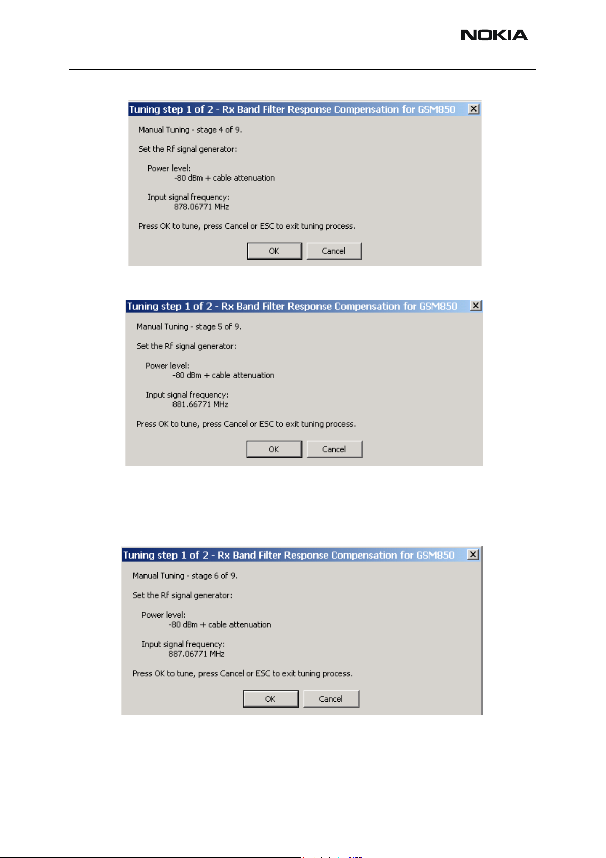
Set the 4th required frequency and level => OK
Set the 5th required frequency and level => OK
CCS Technical Documentation
Set the 6th required frequency and level => OK
Page 56 Copyright Nokia. All rights reserved. Issue 1 07/03
Page 59
Company confidential NEM-2
CCS Technical Documentation
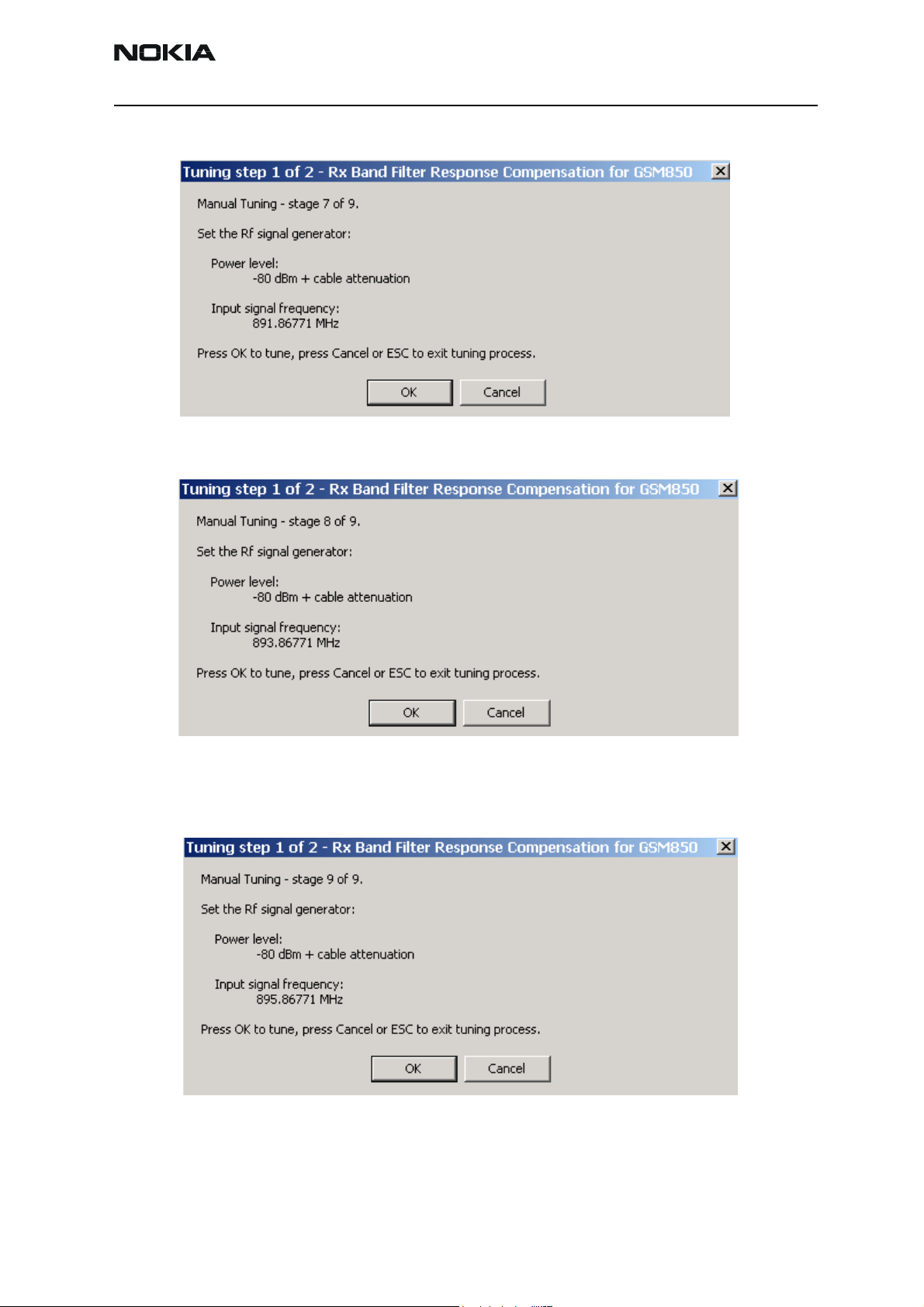
Set the 7th required frequency and level => OK
Set the the 8th required frequency and level => OK
Set 9th required frequency and level => OK
Issue 1 07/03 Copyright Nokia. All rights reserved.. Page 57
Page 60

NEM-2 Company confidential
CCS Technical Documentation
Typical values and limits in Rx Band Filter Response Compensation GSM850:
Input
Channel
118 867.26771 -1.266 -10 3.5
128 869.26771 -0.641 -3.5 3.5
140 871.66771 -0.188 -3.5 3.5
172 878.06771 -0.094 -3.5 3.5
190 881.66771 -0.188 -1 1
217 887.06771 -0.391 -3.5 3.5
241 891.86771 -0.266 -3.5 3.5
251 893.86771 -0.359 -3.5 3.5
261 895.26771 -0.453 -10 3.5
frequency
(MHz)
Typ. Low limit (dB) High limit (dB)
Press “Save and Continue” to continue with 1900MHz band.
Repeat the same steps as for the GSM850 band above.
Page 58 Copyright Nokia. All rights reserved. Issue 1 07/03
Page 61

Company confidential NEM-2
CCS Technical Documentation
Set the first required frequency and level => OK
Set the 2nd required frequency and level => OK
Issue 1 07/03 Copyright Nokia. All rights reserved.. Page 59
Page 62
NEM-2 Company confidential
Set the 3rd required frequency and level => OK
CCS Technical Documentation
Set the 4th required frequency and level => OK
Set the 5th required frequency and level => OK
Page 60 Copyright Nokia. All rights reserved. Issue 1 07/03
Page 63

Company confidential NEM-2
CCS Technical Documentation
Set the 6th required frequency and level => OK
Set the 7th required frequency and level => OK
Set the 8th required frequency and level => OK
Issue 1 07/03 Copyright Nokia. All rights reserved.. Page 61
Page 64

NEM-2 Company confidential
Set the 9th required frequency and level => OK
CCS Technical Documentation
Page 62 Copyright Nokia. All rights reserved. Issue 1 07/03
Page 65

Company confidential NEM-2
CCS Technical Documentation
Typical values and limits in Rx Band Filter Response Compensation GSM1900:
Input
Channel
495 1927.06771 -0.25 -10 3.5
512 1930.26771 0.73 -3.5 3.5
537 1935.26771 1.05 -3.5 3.5
585 1945.06771 0.74 -3.5 3.5
661 1960.06771 0.02 -1 1
736 1975.06771 0.65 -3.5 3.5
794 1986.66771 -0.52 -3.5 3.5
810 1989.86771 -1.07 -3.5 3.5
835 1994.86771 -1.45 -10 3.5
frequency
(MHz)
Typ. Low limit (dB)
High limit
(dB)
Issue 1 07/03 Copyright Nokia. All rights reserved.. Page 63
Page 66

NEM-2 Company confidential
Press “Save and continue” to end the tuning process. The following message appears:
CCS Technical Documentation
Page 64 Copyright Nokia. All rights reserved. Issue 1 07/03
Page 67

Company confidential NEM-2
CCS Technical Documentation
Transmitter tuning
TX Power Level Tuning
Power Meter (or Spectrum analyzer) needed
With Tx Power Level Tuning, the coefficients are adjusted for each power level
Must be done separately on all bands!
Start Power Level tuning at GSM850, then continue at GSM1900 band.
In GSM850 and GSM1900 bands the power level tuning is made only for high PA mode.
Tuning => Tx power level tuning
Remember to take the jig and cable attenuations into account!
Issue 1 07/03 Copyright Nokia. All rights reserved.. Page 65
Page 68

NEM-2 Company confidential
Select “Start”, tuning begins automatically from the GSM850 band
CCS Technical Documentation
Make the required adjustments of the spectrum analyzer as shown on the picture and
press “OK”..
The coefficient table lists the power level, coefficient, target dBm and DAC value for each
power level.
The tuned power level can be chosen by using up and down arrows or mouse.
Page 66 Copyright Nokia. All rights reserved. Issue 1 07/03
Page 69

Company confidential NEM-2
CCS Technical Documentation
The current power level is shown with inverse colors.
The tuning value can be adjusted with “-“ and “+” keys
GSM850: Tune base level and power levels 19,15 and 5 to target level .
Press “Save and Continue” to go to the next band.
Issue 1 07/03 Copyright Nokia. All rights reserved.. Page 67
Page 70

NEM-2 Company confidential
GSM1900: tune base level and power levels 15, 11 and 0 to target level.
CCS Technical Documentation
Change the adjustments of the spectrum analyzer as shown on the picture and press
“OK”.
Page 68 Copyright Nokia. All rights reserved. Issue 1 07/03
Page 71

Company confidential NEM-2
CCS Technical Documentation
Typical values: GSM850
Power level PA high mode
5 0.6- 0.9
7 -
15 0.2 - 0.25
19 0.13- 0.18
Base 0.1- 0.15
Adjust the power levels if needed by using the “-” and “+” keys.
Typical values: GSM1900
Power level PA high mode
0 0.55- 0.75
11 0.2- 0.3
15 0.15 - 0.2
Base 0.1- 0.15
Adjust the power levels as with GSM850.
Finally press “Save and Continue” to end the tuning process.
Issue 1 07/03 Copyright Nokia. All rights reserved.. Page 69
Page 72

NEM-2 Company confidential
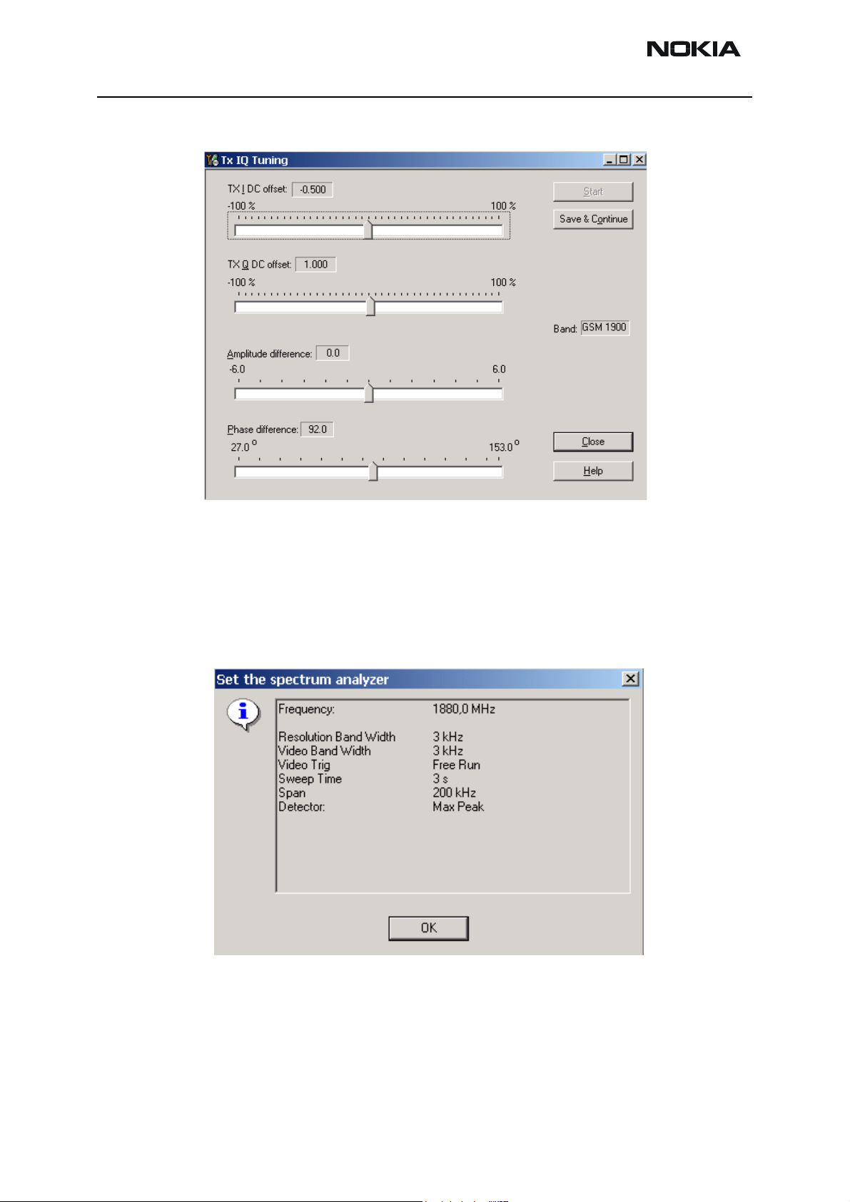
TX I/Q Tuning
Spectrum analyzer needed
Tx IQ Tuning allows changing the Tx I DC Offset, Tx Q DC Offset, Amplitude difference
and Phase difference
Must be done separately on each band!
Changing from 850 to 1900 is made automatically.
Remember to take jig and cable attenuations into account!
Select Tuning => Tx_IQTuning
CCS Technical Documentation
The tuning is done by setting each of the sliders to desired value.
The sliders can be changed only when the tuning is ongoing.
The order of tuning should be same as the order of the sliders e.g. the Tx I DC Offset is
tuned first and Phase difference is tuned last.
Use <= , =>, PgUp or PgDn keys
Tx IQ Tuning limits are the same for all bands GSM850 and GSM1900:
Tuning limits:
I DC Offset -6…+6
Q DC Offset -6…+6
Amplitude difference -1…+1
Phase difference
- 80°…100°
Page 70 Copyright Nokia. All rights reserved. Issue 1 07/03
Page 73

Company confidential NEM-2
CCS Technical Documentation
Tuning starts at the GSM850 band automatically when you press “Start” . Move the sliders to reach values within specified limits
Make the required adjustments of the spectrum analyzer as shown in the picture:
Issue 1 07/03 Copyright Nokia. All rights reserved.. Page 71
Page 74
NEM-2 Company confidential
Press “Save and Continue” to go to the next band..
CCS Technical Documentation
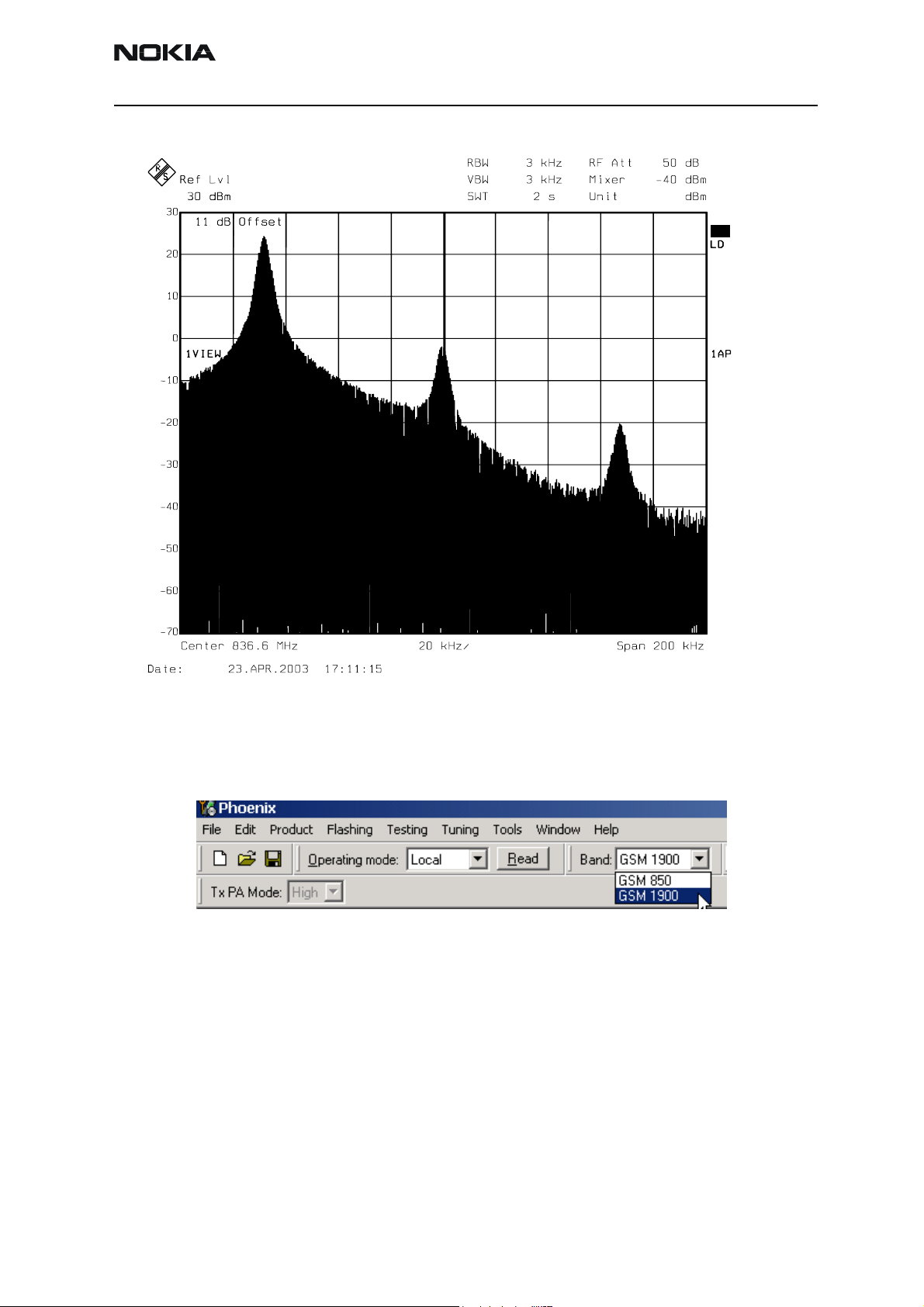
Make the required adjustments of the spectrum analyzer for GSM1900 as shown in the
picture.
Tune LO leak to minimum with TXI/TXQ DC offset control (f0 on spectrum analyzer
screen)
Tune wrong sideband to minimum using Amplitude/Phase difference controls (f0+68kHz
Page 72 Copyright Nokia. All rights reserved. Issue 1 07/03
Page 75
Company confidential NEM-2
CCS Technical Documentation
on spectrum analyzer screen)
Choose “Save and Continue” to end tuning at the GSM850 band when values are within
limits
.
Finally press “Save and Continue” to stop the tuning process.
Issue 1 07/03 Copyright Nokia. All rights reserved.. Page 73
Page 76

NEM-2 Company confidential
CCS Technical Documentation
Service Tool Concept For Baseband Tuning Operations
EM calibrations should be carried out in JBV-1 Docking Station equipped with DA-1
Docking Station Adapter
Note: RF tunings must be carried out in MJ-6 module jig, JBV-1
Docking Station Adapter can only be used for RF testing purposes
Power to JBV-1 should be supplied from an external DC power supply, not FPS-8 prommer
JBV-1 input voltages:
• Maximum + 16 VDC
• Nominal input for RF tunings is +12 V DC.
Note! RF tunings must be carried out in JXS-2 with DA-1 and JBV-1!
Page 74 Copyright Nokia. All rights reserved. Issue 1 07/03
Page 77
Company confidential NEM-2
CCS Technical Documentation
Service Concept for NEM-2 Baseband tunings
Item: Type: Service accessory: Product code:
1 JBV-1 Docking station 0770298
2 DA-1 Docking station adapter 0774288
3 CA-5S EM calibration cable for
JBV-1 and R1011
4 XRS-6 RF cable SMA to N-connec-
tor
5 PCS-1 Power cable for JBV-1 0730012
6 DAU-9S MBUS cable 0730108
7 PKD-1 SW protection key 0750018
8 Phoenix Service SW
9 DKU-2 Tomahawk to USB cable 0730238
0730283
0730231
Issue 1 07/03 Copyright Nokia. All rights reserved.. Page 75
Page 78

NEM-2 Company confidential
Baseband Tuning operations
Energy Management Tuning
External power supply needed.
EM Calibration is used for calibrating Battery and Charger settings of the phone.
Preparation for EM Calibration:
- Connect DC Cable CA-5S between JBV-1 and Vin of Phone for Charger calibration.
- Connect 12…15 V from Power Supply to JBV-1.
- NOTE! Check that connection is F-BUS (does not work with M-BUS!).
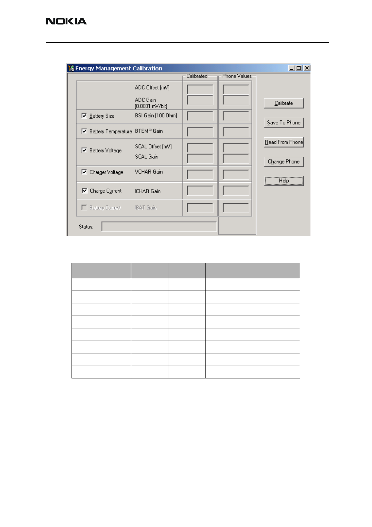
Select Maintenance => Tuning => Energy Management Calibration.
CCS Technical Documentation
Energy Management values to be calibrated are checked.
Select “Read from Phone” to show the current values in the phone memory and to check
that the communication with the phone works.
Page 76 Copyright Nokia. All rights reserved. Issue 1 07/03
Page 79
Company confidential NEM-2
CCS Technical Documentation
Select “Calibrate” to run the selected calibrations.
Limits for Energy Management Calibration:
Parameter Min. Max Note
ADC gain 25400 29000 VBatt, BSI, BTemp
DC offset -50 50 ADC voltage offset
BSI gain 970 1100 ADC BSI calibration gain
BTEMP gain 2075 2275 ADC BTEMP calibration gain
VBAT gain 10000 11000 ADC VBATT Voltage gain
VBAT offset 2300 2900 ADC VBATT Voltage offset scale
VCHAR 58000 62000 Charge voltage
ICHAR 4050 4800 Charge current
If values shown are within limits select “Save To Phone” to save the values in the phone.
NOTE! Only the values of the checked tunings (Battery size, Battery Temperature etc…)
are saved.
Close the “Energy Management Calibration” – dialog to end tuning.
You must manually switch the phone on after exiting “Energy Management Calibration”
– dialog.
Issue 1 07/03 Copyright Nokia. All rights reserved.. Page 77
Page 80

NEM-2 Company confidential
LCD Contrast Tuning
Extra equipment not needed
This function is used to calibrate the LCD Contrast
Must be done when LCD module is replaced and there is a considerable difference in
the contrast!
Select TEST mode if not already selected.
Select Maintenance => Testing => Display Test
Select Test =>Pattern test
CCS Technical Documentation
Select Test Pattern => Chess pattern
Select Lights => Display
Select => Send To Phone.
Page 78 Copyright Nokia. All rights reserved. Issue 1 07/03
Page 81

Company confidential NEM-2
CCS Technical Documentation
Select Maintenance => Testing => Display Tune
Press “Default” button and following default values will be set;
“Contrast offset slider” is set to 0% (See picture below)
“Contrast Factory offset” slider is set 41
Tune the Contrast by using “Contrast Factory offset” slider..
Close the “Display Tune” – dialog to end tuning.
Check the contrast from the Phone UI.
Check that the brightness has been set to default from Phone’s menu 4-4-5
Issue 1 07/03 Copyright Nokia. All rights reserved.. Page 79
Page 82

NEM-2 Company confidential
CCS Technical Documentation
Page 80 Copyright Nokia. All rights reserved. Issue 1 07/03
Page 83

Company confidential NEM-2
CCS Technical Documentation
Flashing Setup Instructions
POS (Point of Sales) Flash Concept via FLS-4
Figure 1: POS flash
Item Type Description Code
FLA-36 Point Of Sales Flash loading adapter 0770467
2 XCS-1 Modular cable 0730218
3 ACF-8 Power supply incl. in 1) 0680032
4 FLS-4S PoS Flash dongle 0080543
5 Phoenix Service SW xxxxxxx
6 DKU-2 Tomahawk USB cable 0730238
Issue 1 07/03 Copyright Nokia. All rights reserved.. Page 79
Page 84

NEM-2 Company confidential
Module Jig Concept
CCS Technical Documentation
Figure 2: Module jig concept
Note! No tuning with MJ-6!
Item Type Description Code
1 MJ-6 Module repair jig 0770463
2 PCS-1 Power cable for MJ-6 0730012
3 XRS-6 RF cable SMA to N-connector 0730231
4 DAU-9S MBUS cable 0730108
5 PKD-1 Software protection dongle 0750018
6 n.a. Phoenix Service SW
7 DKU-2 Tomahawk to USB cable 0730238
SMA-BNC audio test cable
Tomahawk audio test cable
MMC Card
Page 80 Copyright Nokia. All rights reserved. Issue 1 07/03
Page 85

Company confidential NEM-2
CCS Technical Documentation
Flash Concept via FPS-8
Figure 3: FPS-8 Flash concept
Item Type Description Code
1 FLA-36 PoS Flash adapter for R1011 0770467
2 XCS-1 Service cable 0730218
3 XCS-4 Service cable 0730178
4 FPS-8 Flash Prommer 0080321
5 Incl. in 4)
6 Incl. in 4)
7 PKD-1 SW Protection key 0750018
8 Phoenix Service SW
9 Incl. in 4) 0680032
10 DKU-2 Tomahawk USB cable 0730238
Issue 1 07/03 Copyright Nokia. All rights reserved.. Page 81
Page 86

NEM-2 Company confidential
JBV-1 Service Concept
CCS Technical Documentation
Figure 4: Service Concept
Item: Type: Service accessory: Product code:
1 JBV-1 Docking station 0770298
2 DA-1 Docking station adapter 0774288
3 CA-5S EM calibration cable for JBV-1 and
R1011
4 XRS-6 RF cable SMA to N-connector 0730231
5 PCS-1 Power cable for JBV-1 0730012
6 DAU-9S MBUS cable 0730108
7 PKD-1 SW protection key 0750018
8 Phoenix Service SW
9 DKU-2 Tomahawk to USB cable 0730238
0730283
Page 82 Copyright Nokia. All rights reserved. Issue 1 07/03
Page 87

Company confidential NEM-2
CCS Technical Documentation
Parallel Flash concept
Figure 5: Parallel flash concept
Item Type Description Code
1 JBV-1 Docking station 0770298
2 DA-1 Docking station adapter 0774288
3 XCS-4 Modular cable RJ45 0730178
4 PCS-1 Power cable for JBV-1 0730012
5 Serial cable 2X from 9)
6 Centronix cable from 9)
7 PKD-1 SW Protection key 0750018
8 Phoenix Service SW
9 FPS-8C Parallel Flash Prommer incl. 5) and 6) 0080396
10 DKU-2 Tomahawk USB cable 0730238
The reflash of 4 phones in parallel does work on 1 USB Hub connected to either USB 1.1
or USB 2.0 Port on the PC side.
Issue 1 07/03 Copyright Nokia. All rights reserved.. Page 83
Page 88

NEM-2 Company confidential
The reflash of more than 4 phones in parallel requires either:
2 separate 4-port USB Hubs conected to PC with USB 2.0 support
or
2 separate USB PCI cards supporting USB 1.1 or USB 2.0 installed in the PC. Each of 2 4port USB Hubs must be connected to the different USB ports on PC side.
CCS Technical Documentation
[This page left intentionally blank]
Page 84 Copyright Nokia. All rights reserved. Issue 1 07/03
 Loading...