

Page 1

CC Technical Documentation
RM-11 Series Transceivers
Service Tools
Issue 1 02/2004 Confidential ©2004 Nokia Corporation
Page 2

RM-11
Service Tools CC Technical Documentation
Contents Page
Model 3205 Service Tools............................................................................................. 3
Flashing and Testing Setups ........................................................................................8
Flashing, Testing, and Tuning with Covers On ...........................................................8
Service Setup 1.......................................................................................................... 9
Service Setup 2........................................................................................................ 10
Service Setup 3........................................................................................................ 11
Automated Tuning and Alignment ............................................................................12
GPS Testing Engine ...................................................................................................13
GPS Testing Equipment.......................................................................................... 14
Page 2 ©2004 Nokia Corporation Confidential Issue 1 02/2004
Page 3

RM-11
CC Technical Document a tion Service Tools
Model 3205 Service Tools
JBV-1 Docking Station DA-12 Docking Station Adapter
0770298 0770603
The Docking Station and the Docking Station Adapter
are needed for Mbus, Fbus, RF, and audio connections.
This setup allows connection between flash prommers.
The Docking Station can be powered by FPS-8 or external power supply.
The flash adapter allows FBUS/MBUS connections for
flashing.
JBA-12 Audio Box CPL-8 GPS/RF Coupler
0770536 0770475
The JBA-12 is required for audio testing at authorized
service centers.
CPL-8 allows testing of the GPS antenna at AMS locations.
Shield Box JSX-1A is required.
Issue 1 02/2004 ©2004 Nokia Corporation Confidential Page 3
Page 4

RM-11
Service Tools CC Technical Documentation
JSX-1A Shield Box DKU-5F Flash Cable
0770346 0780738
The Shield Box allows RF radiated tests and antenna
testing. Contact the Americas AMS in Melbourne, FL
for more information on how to obtain one.
For use with the Spirent UPST and UMPP service software.
Note: The cable cannot be used as a straight through
USB connection cable.
FPS-8 Flash Prommer ADS-8 Audio Cable
0080321 0730268
The Flash Prommer FPS-8 is used for heavy flash at
authorized service centers.
The Audio Cable connects to the Audio Box (JBA-12).
Page 4 ©2004 Nokia Corporation Confidential Issue 1 02/2004
Page 5
RM-11
CC Technical Documentation Service Tools
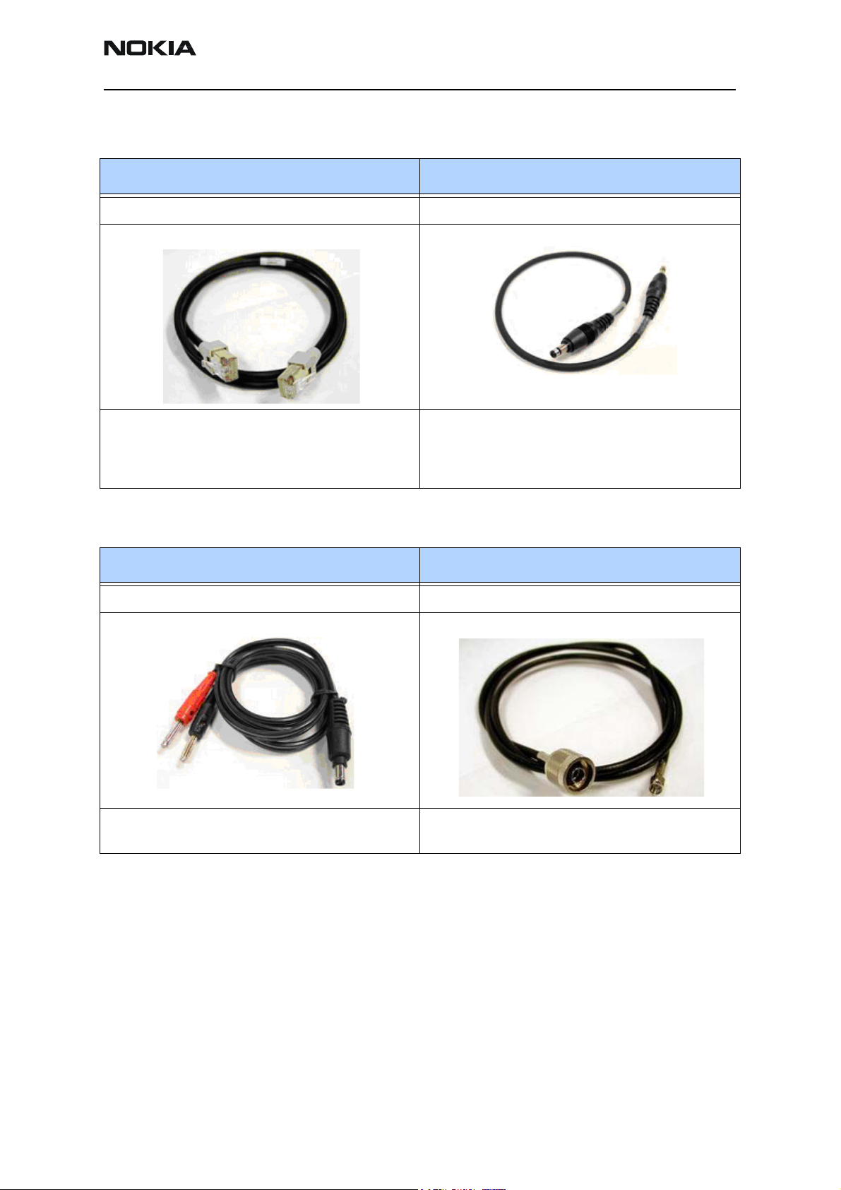
XCS-4 Mbus/Fbus Cable CA-5S DC Service Cable
0730178 0730283
XCS-4 Service Cable is a modular cable for flashing
DCT4 products.
The DC Service Cable (CA-5S) connects the docking
station (JBV-1) to the charger connection (Vin) of the
phone to conduct EM calibration.
Note: CA-5S replaces the SCB-3 cable (0730114).
PCS-1 Power Cable XRS-6 RF Cable
0730012 0730231
The PCS-1 Power Cable is used to connect the service
tools (JBV-1, DA-12) to an external power supply.
The XRS-6 Cable is used to connect service tools to RF
measuring equipment.
Issue 1 02/2004 ©2004 Nokia Corporation Confidential Page 5
Page 6

RM-11
Service Tools CC Technical Documentation
FLS-4S POS Flash Dongle DAU-9T FBUS Data Cable
0080543 0730267
The Point of Sale (POS) flash is a low-cost software
upgrade tool. This requires XCS-1 cable and ACF-8 for
operation.
FBUS cable DAU-9T provides a connection from the
serial port of the computer to the system connector of
the phone.
DAU-9S Cable CA-25RS RF Test Probe
0730108 0730316
This is a general-purpose cable to support F / MBUS
communication between a Mod-10 device and a PC.
The CA-25RS allows testing of the CDMA RF.
Page 6 ©2004 Nokia Corporation Confidential Issue 1 02/2004
Page 7

RM-11
CC Technical Documentation Service Tools
CA-22DS Service Connector MJ-18 Module Jig
0730311 0770599
This cable is used with FLS-4S or FLC-20 for bottomconnector flashing.
This jig allows phone PWB-level service and troubleshooting for authorized service centers.
PKD-1 SW Security Device SRT-10 Camera Removal Tool
0750018 0770666
SW security device (PKD-1) is a hardware device that,
when connected to the parallel (LPT) port of the PC,
enables the use of service software. Without the dongle present, it is not possible to use the service software. Printers or other peripheral devices can be
connected to the PC through the dongle, if needed.
Caution: Make sure that you have switched off the PC
and the printer before making connections!
SRT-10 is used to remove the camera. For detailed
camera module disassembly/assembly instructions, see
the Disassembly/Assembly chapter.
Issue 1 02/2004 ©2004 Nokia Corporation Confidential Page 7
Page 8

RM-11
Service Tools CC Technical Documentation
Flashing and Testing Setups
POS Flash Setup 1 POS Flash Setup 2
FLC-20 and CA-22DS DKU-5F
POS Flash Setup 3 Service Center Flash Setup 4
FLS-4S and CA-22DS FPS-8 prommer, JBV-1, and DA-12
Flashing, Testing, and Tuning with Covers On
Tightened performance specifications require more precise equipment and methods for
testing and alignment. Manual tuning ca not provide accurate results for the RM-11,
which means that this test has to be automated.
These setups are intended to be with the Phoenix Service Software. Both manual testing
and automated tuning are permitted with Phoenix Service Software.
Page 8 ©2004 Nokia Corporation Confidential Issue 1 02/2004
Page 9

RM-11
CC Technical Documentation Service Tools
Service Setup 1
7
8
6
5
4
3
2
1
5
Item Name Type Code
1 Docking Station JBV-1 0770298
2 Docking Station Adapter DA-12 0770603
3 DC Power Cable PCS-1 0770012
4 Modular Cable XCS-4 0730178
5 Flash Prommer Box FPS-8 0080321
6 Printer Cable (included with FPS-8) CA-10DS 0730298
7 D9-D9 Cable (included with FPS-8) AXS-4 0730090
8 SW Protection Key PKD-1 0750018
9 AC Charger ACP-8F 0680032
Issue 1 02/2004 ©2004 Nokia Corporation Confidential Page 9
Page 10

RM-11
Service Tools CC Technical Documentation
Service Setup 2
5
2
3
1
Item Name Type Code
1 Module Jig MJ-18 0770599
2 DC Power Cable PCS-1 0730012
3 RF Antenna Cable XRS-6 0730231
4 Service MBUS Cable DAU-9S 0730108
5 SW Protection Key PKD-1 0750018
4
Page 10 ©2004 Nokia Corporation Confidential Issue 1 02/2004
Page 11

RM-11
CC Technical Documentation Service Tools
Service Setup 3
7
4
6
3
2
1
5
Item Name Type Code
1 Docking Station JBV-1 0770298
2 Docking Station
Adapter
3 DC Service Cable CA-5S 0730283
4 RF Antenna Cable XRS-6 0730231
5 DC Power Cable PCS-1 0730012
6 Service MBUS Cable DAU-9S 0730108
7 SW Protection Key PKD-1 0750018
DA-12 0770603
Issue 1 02/2004 ©2004 Nokia Corporation Confidential Page 11
Page 12

RM-11
Service Tools CC Technical Documentation
Automated Tuning and Alignment
This setup is used for tuning of the handset at Nokia Authorized Service Centers.
JBV-1 +
DA-12
Figure 1: Tuning and alignment diagram
Use the following equipment for automated tuning and alignment.
Note: A Test Sequence File is required to perform “Auto tune” on this phone. In addition, Phoenix
needs to have the Auto Tune function installed. Consult your local Nokia After Market Services office
more information.
Table 1: Automated tuning and alignment equipment list
Item Name MFR Model # QTY Comment
1 Vector Signal Analyzer Agilent E4406A 1 Options B78, BAC and BAE
2 Signal Generator Agilent E4421B 1 Digital signal generator with high stability
oscillator and high spectral purity
3 Momentum Series Agilent 8960C 1 CDMA tester for IS-95, IS-2000, and
AMPS protocols
4 Power Supply Keithly K2306 2 Programmable with sense wire
5 Win2000 PC Dell with Pentium III or above, network
card, 256M RAM, 20GB HD, CD-ROM, etc.
6 NI-GPIB Interface NI GPIB-USB-A 2 USB to GPIB adapter (184983G-01)
Page 12 ©2004 Nokia Corporation Confidential Issue 1 02/2004
Page 13

RM-11
CC Technical Documentation Service Tools
Table 1: Automated tuning and alignment equipment list (Continued)
Item Name MFR Model # QTY Comment
7 Docking Station Nokia JBV-1 1 Consult your local Nokia After Market
Services office for more information
8 RF Switches Green Hill TVi9901 1 Consult your local Nokia After Market
Services office for more information
GPS Testing Engine
Use this setup for testing the GPS engine at Nokia Authorized Service Centers. Both
Galvanic and Radiated tests are supported. The GPS Test component in Phoenix provides
functionality to perform these tests. Refer to the Troubleshooting - GPS section for more
details regarding GPS engine troubleshooting.
DA-12
Figure 2: GPS Galvanic Testing
DA-12
releaselatest
Issue 1 02/2004 ©2004 Nokia Corporation Confidential Page 13
Page 14

RM-11
Service Tools CC Technical Documentation
Figure 3: GPS radiated testing
GPS Testing Equipment
• Power Supply
• Signal Generator up to 2 GHz
• Computer (Pentium 3, W2000)
• JBV-1 Docking Station
• DA-12 Docking Station Adaptor
•PCS-1 DC Power Cable
•DAU-9S M/F-Bus Cable
• RF Test Cables (for GPS RF Port)
• Latest Release Phoenix AMS version w/ GPS Test Component
Page 14 ©2004 Nokia Corporation Confidential Issue 1 02/2004
 Loading...