

Page 1

CC Technical Documentation
RM-11 Series Transceivers
Disassembly
Issue 1 02/2004 Confidential ©2004 Nokia Corporation
Page 2
RM-11
Disassembly CC Technical Documentatio n
Step-by-Step Disassembly Instructions
Always use ESD protection when assembling or dissasembling a phone.
Figure 1: ESD protection equipment
Disassembly Instructions
Step-by-Step Disassembly Instructions (Model 3205)
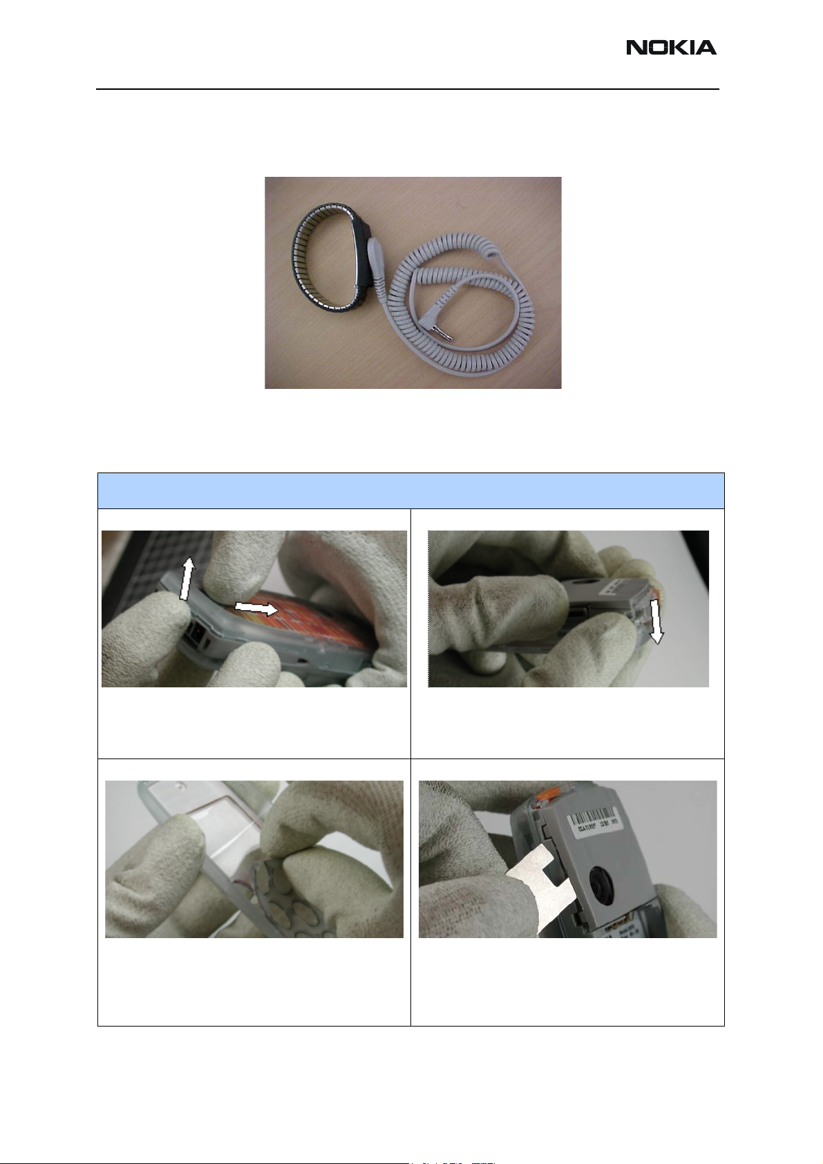
1. Hold the phone with the top down, facing you.
Press the Release Key and push the battery cover
out from the phone in the direction indicated (see
arrows in the above photo).
2. Remove the A-Cover by gently pulling from the top
end in the direction indicated by the above arrow.
3. Remove the Keymat. 4. Use SRT-10 camera removal tool to remove the
Antenna.
Note: Be careful not to damage mechanical parts. Do
not touch the antenna plate inside unless you are wearing proper ESD gloves.
Page 2 ©2004 Nokia Corporation Confidential Issue 1 02/2004
Page 3

RM-11
CC Technical Documentation Disassembly
Step-by-Step Disassembly Instructions (Model 3205)
5. Remove the six screws that hold the C-Cover in
place (torque 21Ncm and speed 480rpm).
7. Remove the UI module from the engine module.
Note: The UI module and the engine board are linked
together by two board-to-board connectors. Be careful
not to touch them.
6. Remove the PWB/UI module from the C-Cover.
UI module and engine module after separation.
8. Remove the microphone by gently pressing on its
edge or by placing tweezers between the frame and
the microphone and lifting it out of the frame.
9. Remove the speaker by lifting it from the guiding
pin.
Note: The speaker is attached into the frame with adhesive tape. Therefore, it may not loosen easily.
Issue 1 02/2004 ©2004 Nokia Corporation Confidential Page 3
Page 4

RM-11
Disassembly CC Technical Documentatio n
Step-by-Step Disassembly Instructions (Model 3205)
10. Open the snaps on both sides of the Display shield
and remove the shield.
Note: Be careful not to damage the shield.
12. Remove the UI board from the LCD frame.
Note: Be careful not to damage the LCD frame.
11. Remove the LCD Module by holding the UI module
in one hand while loosening the LCD frame a little at
the same time at one side. Press the LCD module gently
from the same side you are loosening until the LCD
Module detaches.
Note: Be careful not to damage the sensitive parts. Do
not press the LCD Module too hard.
13. Remove the Power Key.
Power Key removal. 14. Lift the Vibra to remove it.
Page 4 ©2004 Nokia Corporation Confidential Issue 1 02/2004
Page 5

RM-11
CC Technical Documentation Disassembly
Step-by-Step Disassembly Instructions (Model 3205)
15. Lift the DC Jack out of its place.
Note: Be careful not to damage the C-Cover when
removing the DC Jack.
17. Remove the Release Key. 18. Remove the A-cut cover from the A-Cover.
16. Use tweezers to lift the Release Spring.
19. Remove the B-cut cover from the B-Cover. 20. Pry the battery out of the phone as indicated.
Issue 1 02/2004 ©2004 Nokia Corporation Confidential Page 5
Page 6

RM-11
Disassembly CC Technical Documentatio n
Page 6 ©2004 Nokia Corporation Confidential Issue 1 02/2004
 Loading...