

Page 1

CC Technical Documentation
RM-11 Series Transceivers
Troubleshooting - GPS
Issue 1 02/2004 Confidential ©2004 Nokia Corporation
Page 2

RM-11
Troubleshooting - GPS CC Technical Documentation
Contents Page
Troubleshooting - Global Positioning System (GPS) Engine........................................ 3
GPS General Block Diagram .......................................................................................3
GPS RF Schematic ......................................................................................................3
GPS Testing .................................................................................................................4
GPS RF Probing Setup ..............................................................................................8
Page 2 ©2004 Nokia Corporation Confidential Issue 1 02/2004
Page 3
RM-11
CC Technical Documentation Troubleshooting - GPS
Troubleshooting - Global Positioning System (GPS) Engine
The RM-11 handset supports 800 AMPS and 800 CDMA / 1900 CDMA + GPS with
IS 2000 capability. The RM-11 engine supports CDMA and GPS functionality for
Enhanced 911 (E911) services.
GPS circuitry utilizes RF signals from satellites stationed in geosynchronous orbit to
determine the latitude and longitude of the handset. The GPS circuitry and the cellular
engine (CE) circuitry are completely separate in the handset. The GPS circuitry is located
almost exclusively on the secondary side of the PWB, underneath the display module.
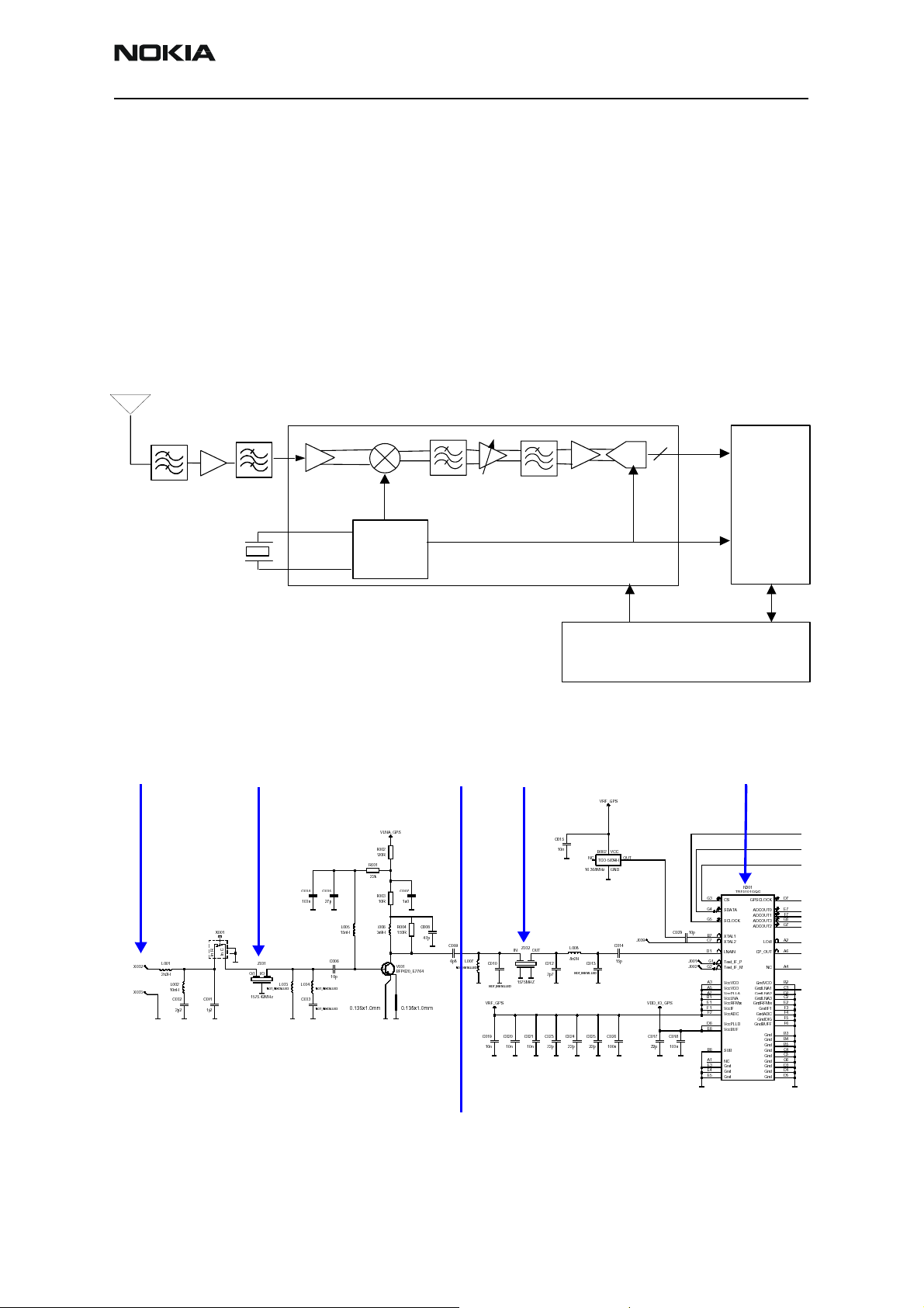
GPS General Block Diagram
LNA
Xtal
16.368MHz
IF = 4.092MHz
FilterFilter
AD
C
AGC
Amp
Synthesiser
TRF510
1
GPS RF
Cellular Baseband
Rx
Data
Out
4
Baseband
Ref
Clk
Figure 1: GPS general block diagram
GPS RF Schematic
RF input GPS RF chip (N001)
Filter 1 (Z001)
Filter 2 (Z002)
GPS
Circuits Located on Bottom Layer
Circuits Located on Top Layer
Figure 2: GPS RF schematic
Issue 1 02/2004 ©2004 Nokia Corporation Confidential Page 3
Page 4

RM-11
Troubleshooting - GPS CC Technical Documentation
GPS Testing
1. Set Local Mode.
Figure 3: Phone Control dialog box
2. Inject -110dBm tone @ 1575.52MHz at GPS connector (X001) with a signal
generator or call box.
Signal Generator
Signal Generator
RF OUT
RF OUT
Figure 4: GPS connector (X001)
3. Open the BB/Hwd menu and select GPS Control.
4. Click the Execute button on the GPS Control dialog box to run a GPS quick test.
Page 4 ©2004 Nokia Corporation Confidential Issue 1 02/2004
Page 5

RM-11
CC Technical Documentation Troubleshooting - GPS
5. Analyze the results of the GPS test in the Test Steps area.
Figure 5: GPS Control dialog box
6. Self-Test Failure:
• Repeat Steps 1-5 for first failure. If the test still fails, continue.
• Inspect all GPS circuit elements around D051.
• If pass visual inspection, then replace D051.
Issue 1 02/2004 ©2004 Nokia Corporation Confidential Page 5
Page 6

RM-11
Troubleshooting - GPS CC Technical Documentation
7. Oscillator Failure:
• Inspect all GPS circuit elements around D051.
• If pass visual inspection, then replace B002.
D051
B002
Figure 6: Component layout - top layer
8. CW Test Failure (see Figure 7):
• Check that signal generator is on and sourcing a signal to the GPS RF input
port (X001).
• Inspect all GPS RF circuit elements.
• Inspect all GPS circuit elements around D051.
• If all visual inspection looks good, then replace GPS RF IC (N001).
Page 6 ©2004 Nokia Corporation Confidential Issue 1 02/2004
Page 7

RM-11
CC Technical Documentation Troubleshooting - GPS
INSPECT
Figure 7: Inspection areas for CW test failure
Issue 1 02/2004 ©2004 Nokia Corporation Confidential Page 7
Page 8

RM-11
Troubleshooting - GPS CC Technical Documentation
GPS RF Probing Setup
1. Turn on the GPS Receiver
2. Inject -25dBm tone @ 1575.52MHz at GPS Connector (X001) with signal generator or Call Box.
Signal Generator
Signal Generator
RF OUT
RF OUT
Figure 8: Signal generator RF OUT
Page 8 ©2004 Nokia Corporation Confidential Issue 1 02/2004
Page 9

RM-11
CC Technical Documentation Troubleshooting - GPS
3. Measure probe points with either a FET probe and a spectrum analyzer set at
center frequency 1575.25MHz, Span = 500kHz, or a voltmeter as specified. See
Table 1 for measurement information that correspond to the test points in
Figure 9.
2 - Probe C014
3 - Probe C015
1 - Probe one of the two
exposed pads that lead into
the Z001
4 - Probe C029
Figure 9: GPS RF probing measurements
Table 1 defines the test points shown in Figure 9.
Table 1: GPS RF test point information
Test Point Description Value Instrument
1 LNA output 1575.25MHz @ -19.5dBm spectrum analyzer
2 2nd BPF output 1575.25MHz @ -21dBm spectrum analyzer
3 TXCO supply V
4 TXCO output freq 16.368MHz @ +6dBm spectrum analyzer
RF_GPS
2.78V (DC) voltmeter
Issue 1 02/2004 ©2004 Nokia Corporation Confidential Page 9
Page 10

RM-11
Troubleshooting - GPS CC Technical Documentation
Page 10 ©2004 Nokia Corporation Confidential Issue 1 02/2004
 Loading...