

Page 1

CC Technical Documentation
RM-11 Series Transceivers
Troubleshooting - RF (Part 1)
Issue 1 02/2004 Confidential ©2004 Nokia Corporation
Page 2

RM-11
Troubleshooting - RF (Part 1) CC Technical Documentation
Contents Page
RF Troubleshooting ....................................................................................................... 3
Equipment List for RF Troubleshooting ......................................................................3
Phoenix Service Software ............................................................................................4
RF (Manual Control) Components in Phoenix ......................................................... 5
Observing Tx Output Spectrum on Analyzer............................................................ 7
Other RF Parameters in Phoenix............................................................................... 9
RF Tuning Parameters in Phoenix .......................................................................... 11
RF AGC Status Components in Phoenix................................................................ 12
CDMA In-Call Testing ..............................................................................................12
CDMA in Call Testing (Low Gain) ........................................................................ 13
CDMA in Call Testing (High Gain)........................................................................ 14
CDMA in Call Testing (AMPS).............................................................................. 15
Summary of Typical Cell Band PDM Readings ........................................................16
Summary of Typical PCS Band PDM Readings .......................................................17
Tx PDM Characteristic Curves (Phone Call Mode) ..................................................19
Rx PDM Characteristic Curve (Phone Call Mode) ...................................................19
Key RF Performance Tests in Call Mode ..................................................................19
Tx Tests................................................................................................................... 19
Rx Tests................................................................................................................... 20
Supply Lines Measurement Using Phoenix............................................................ 21
12 RF-related Supply Lines Distribution................................................................ 22
Supply Lines Distribution by RF Components....................................................... 23
12 Supply Lines Resistance to Ground................................................................... 23
Top RF-related Failures Seen in FLALI ....................................................................24
Top RF-related Failures Seen in FINUI ....................................................................24
Page 2 ©2004 Nokia Corporation Confidential Issue 1 02/2004
Page 3
RM-11
CC Technical Documentation Troubleshooting - RF (Par t 1)
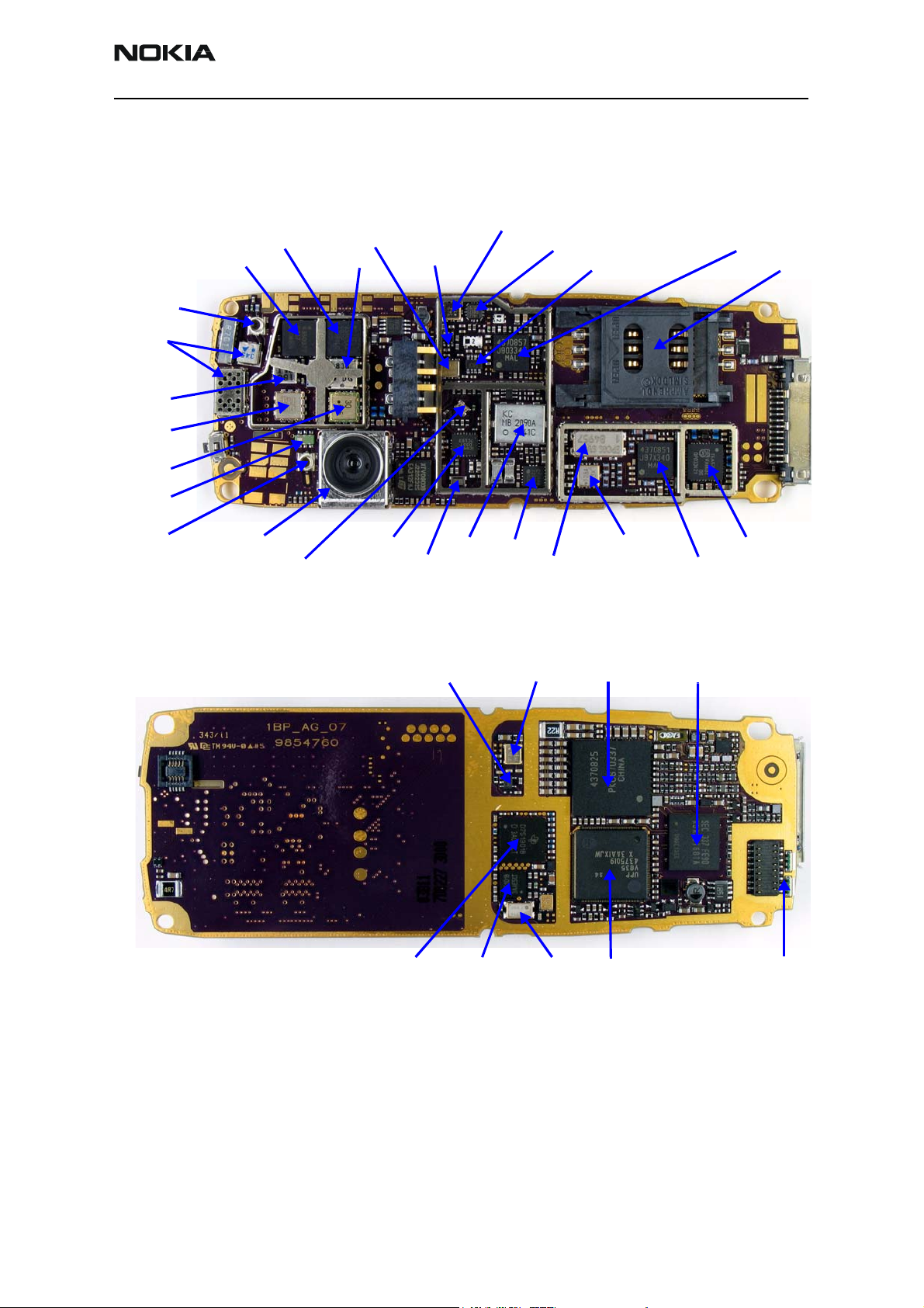
RF Troubleshooting
The RM-11 features 1900MHz PCS CDMA, 800MHz Cell CDMA and AMPS, an internal
antenna, GPS, an FM radio, a RUIM card, a color LCD, a VGA camera, and a flashlight.
PCS TX Split-band SAW Filter
Cell TX PA
PCS TX PA Cell Isolator
GPS
Connector
GPS LNA
and Filter
PCS
Isolator
PCS
Duplexer
Cell
Duplexer
Diplexer
Cell TX SAW Filter
PCS TX Switch
PCS TX Driver “Hornet”
Cell TX Driver “Tomcat” SIM Card
Robin TX Up-converter
RF Connector
VGA Camera
PCS RX FR
SAW Filter
RX IC “Alfred”
Cell RX RF
SAW Filter
VCO
PLL IC
Figure 1: RM-11 RF components
VCTCXO Inverter VCTCXO UEM
GPS BB IC GPS RF IC
RX IF AMPS Filter
RX IF CDMA Filter
GPS TCXO
UPP
FM Radio IC
Batman RX Downconverter
Memory
Flashlight
Figure 2: RM-11 Baseband components
Equipment List for RF Troubleshooting
Use the following equipment to troubleshoot the RM-11 RF:
• Computer with Phoenix
• Agilent 8960 CDMA call box
Note: (If 8960 is not available, then a Signal Generator is needed.
Issue 1 02/2004 ©2004 Nokia Corporation Confidential Page 3
Page 4
RM-11
Troubleshooting - RF (Part 1) CC Technical Documentation
• Power supply
• Diagnostic test jig
• RF connector snap cable
• Spectrum analyzer
• Active FET probe
• Tomahawk headset and universal headset for FM radio
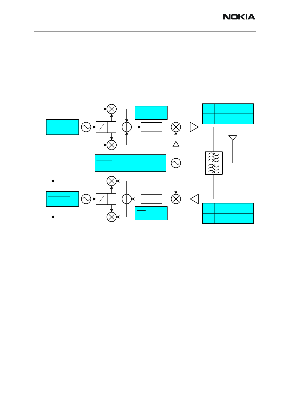
824.04 - 848.97 MHz
TX I
TX VHF LO
CELL 346.2 MHz
PCS 416.2 MHz
TX Q
346.2=173.1*(2)
416.2=208.1*(2)
256.2=128.1*(2)
TX IF
CELL 173.6 MHz
PCS 208.1 MHz
°0
1
2
°90
UHF LO
CELL 997.14 - 1022.07 MHz, 30 kHz Step
PCS 2058.10 - 2118.05 MHz, 50 kHz Step
TX Block
CELL
1850.00 - 1909.95 MHz
PCS
30 kHz Steps
50 kHz Steps
RX I
RX VHF LO
CELL 256.2 MHz
PCS 256.2 MHz
RX Q
1
2
Figure 3: RF troubleshooting equipment diagram
Phoenix Service Software
In the RF environment, Phoenix SW provides 10 components for troubleshooting:
• Phone Control in DSP
• RF Main Mode in RF
• CDMA Control in DSP
•RF PDM in RF
• Gen I/O in RF
• RF Register R/W in RF
°0
°90
RX Block
RX IF
CELL 128.1 MHz
PCS 128.1 MHz
869.04 - 893.97 MHz
CELL
1930.00 - 1989.95 MHz
PCS
30 kHz Steps
50 kHz Steps
•UHF Synthesizer in RF
• Batch Tune in RF
• RF Tuning in RF
•RF AGC Status in RF
Page 4 ©2004 Nokia Corporation Confidential Issue 1 02/2004
Page 5
RM-11
CC Technical Documentation Troubleshooting - RF (Par t 1)
RF (Manual Control) Components in Phoenix
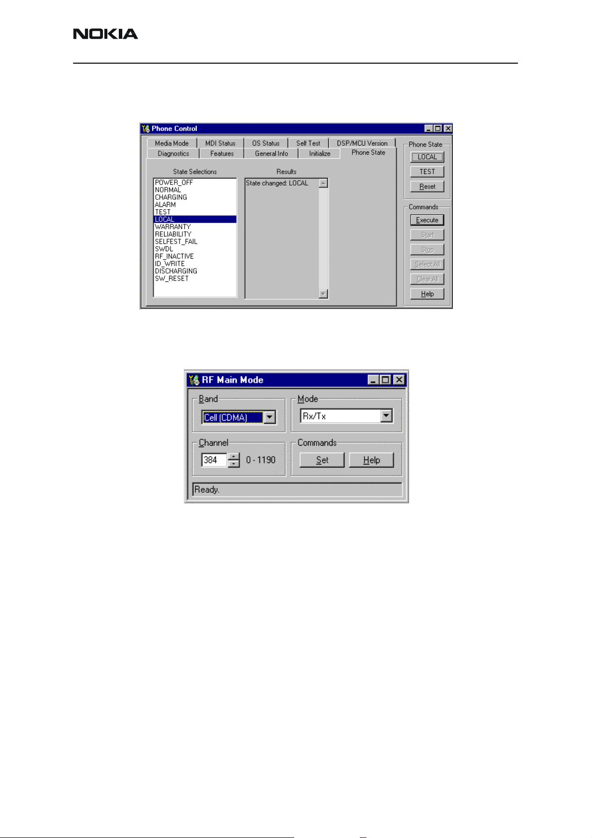
c Phone Control in DSPc Phone Control in DSP
Figure 4: Phone Control dialog box in DSP
d RF Main Mode in RFd RF Main Mode in RF
Figure 5: RF Main Mode dialog box in RF
Issue 1 02/2004 ©2004 Nokia Corporation Confidential Page 5
Page 6
RM-11
Troubleshooting - RF (Part 1) CC Technical Documentation
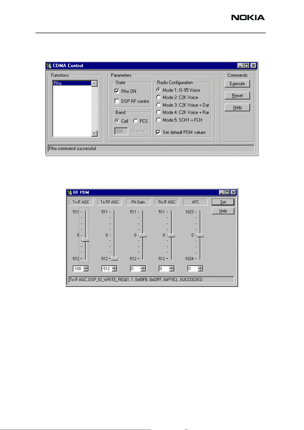
e CDMA Control in DSPe CDMA Control in DSP
Figure 6: CDMA Control dialog box in DSP
f RF PDM in RFf RF PDM in RF
Figure 7: RF PDM dialog box in RF
Page 6 ©2004 Nokia Corporation Confidential Issue 1 02/2004
Page 7
RM-11
CC Technical Documentation Troubleshooting - RF (Par t 1)
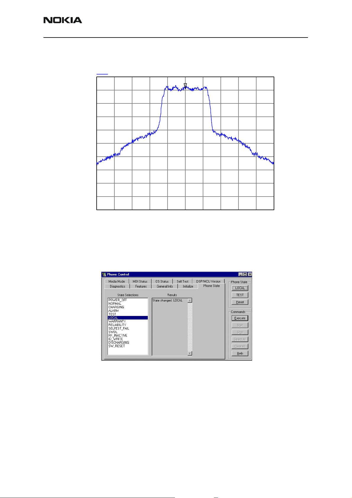
Observing Tx Output Spectrum on Analyzer
CDMA signal obtained in Local mode by turning modulation ON
dBm
0
-10
-20
-30
-40
-50
-60
-70
-80
CDMA signal on channel 384
1
-90
-100
Start: 834.020000 MHz Stop: 839.020000 MHz
Res BW: 30 kHz Vid BW: 30 kHz Sweep: 50 ms
6/23/03 3:55:47 PM HP8562E,007
Figure 8: Tx output spectrum
To observe a Tx waveform using a spectrum analyzer:
1. Enable Local Mode on the Phone Control dialog box.
Figure 9: Enabling Local Mode on the Phone Control dialog box
Issue 1 02/2004 ©2004 Nokia Corporation Confidential Page 7
Page 8
RM-11
Troubleshooting - RF (Part 1) CC Technical Documentation
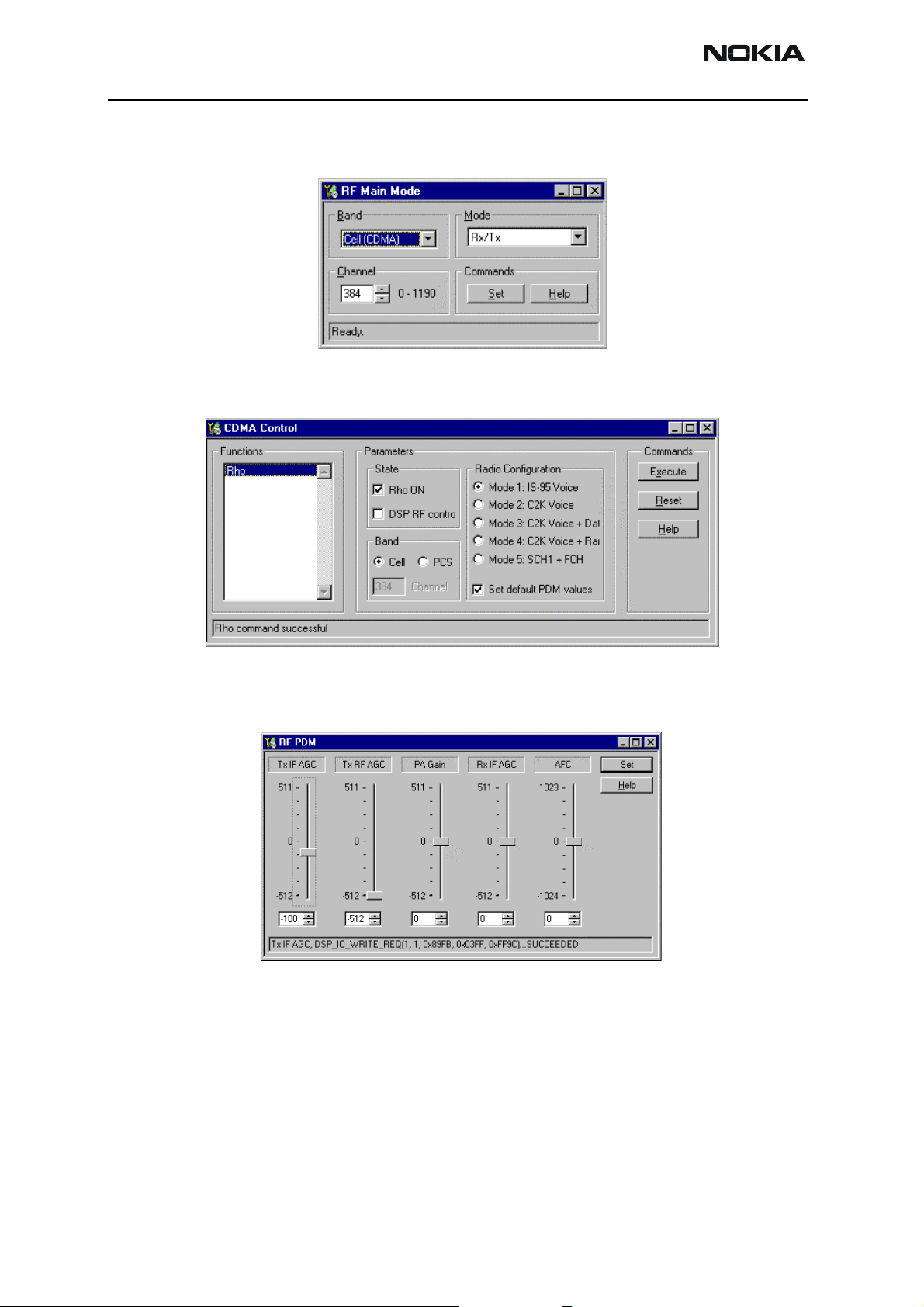
2. Select Cell (CDMA) in the Band field, and Rx/Tx (Tx path enabled) in the Mode
field on the RF Main Mode dialog box.
Figure 10: RF Main Mode dialog box
3. Select the Rho ON check box in the State area on the CDMA Control dialog box.
Figure 11: CDMA Control dialog box
4. Adjust the three Tx AGC settings for the proper output power level on the RF
PDM dialog box.
Figure 12: RF PDM dialog box
Page 8 ©2004 Nokia Corporation Confidential Issue 1 02/2004
Page 9

RM-11
CC Technical Documentation Troubleshooting - RF (Par t 1)
Following are definitions of the settings on the RF PDM dialog box:
• Automatic Frequency Control (AFC):
Control range from -1024 to +1023. Used as a control line to tune the
VCTCXO. Monitor the change in frequency of the VCTCXO as the AFC is
changed. Use in Local Mode only.
• Automatic Gain Control for Transmitter (Tx AGC):
Consists of the Tx IF AGC, the Tx RF AGC, and the PA AGC. Used as control
lines to adjust the transmitter output levels. Monitor the Tx power with call
box or analyzer. Local Mode only.
• Automatic Gain Control for Receiver (Rx AGC):
Consists of the Rx IF AGC. Used as control line to adjust the receiver input
level. Local Mode use only.
Other RF Parameters in Phoenix
g Gen I/O in RF
Figure 13: RF Gen I/O dialog box in RF
Issue 1 02/2004 ©2004 Nokia Corporation Confidential Page 9
Page 10

RM-11
Troubleshooting - RF (Part 1) CC Technical Documentation
h RF register Read/Write in RF
Figure 14: RF Register R/W dialog box
i Frequency Calculator in RF
Figure 15: UHF Synthesizer dialog box
Page 10 ©2004 Nokia Corporation Confidential Issue 1 02/2004
Page 11

RM-11
CC Technical Documentation Troubleshooting - RF (Par t 1)
RF Tuning Parameters in Phoenix
j Batch Tune in RF
Figure 16: Batch Tune dialog box
k RF Tuning in RF
Figure 17: RF Tuning dialog box
Note: When reading the tuning parameters from the phone, always use the “Read All” button
in order to read the entire set of tuning values.
Issue 1 02/2004 ©2004 Nokia Corporation Confidential Page 11
Page 12

RM-11
Troubleshooting - RF (Part 1) CC Technical Documentation
RF AGC Status Components in Phoenix
l RF AGC Status in RF
LNA Gain (High/Low)
Rx IF AGC PDM Settings BBAMP Gain Settings
Note: This RF AGC Status component only works in Call Mode. Always measure resistance with the
phone powered OFF.
CDMA In-Call Testing
See Step 1 below
Rx RF AGC PDM SettingsPA AGC PDM Settings
Tx IF AGC PDM Settings
Figure 18: CDMA In-call testing
Note: There are two CDMA bands for this phone (Cell and PCS). Repeat steps 1-6 for each band to
verify performance.
Page 12 ©2004 Nokia Corporation Confidential Issue 1 02/2004
Page 13

RM-11
CC Technical Documentation Troubleshooting - RF (Par t 1)
1. Connect phone to call box via RF port (X814). (Add RF cable loss on call box
≅0.2 dB Cell band, ≅0.4dB PCS).
2. Power up the phone in “Normal” mode.
3. If you need to load CDMA PRL, first put the phone into Local Mode. Load the PRL;
set the phone back to Normal Mode. Make sure to set the RF channel and SID
according to PRL.
4. Register the phone and establish a call at –65 dBm call box sector power.
• If you cannot register the phone, set the sector power to –25 dBm and try
again.
• If a call cannot be made in either PCS or Cell band, then proceed with Local
Mode troubleshooting. (See the note following Figure 18.)
5. If the phone call is successful, open the AGC Status under the RF menu.
6. Select the Enable Trace check box on the AGC Status window.
CDMA in Call Testing (Low Gain)
See step 7.
See step 8.
Figure 19: CDMA in call testing (Low Gain)
Table 1 includes the AGC tolerances for the Cell CDMA and PCS CDMA bands.
Table 1: AGC tolerances
Band Rx AGC IF AGC RF AGC PA AGC
Cell CDMA >40 <40 125+-30 <-300
PCS CDMA >40 <40 120+-30 <-300
7. In a phone call, handoff to the center channel (Ch. 600 for PCS, or Ch. 384 for
Cell), and verify that the call box sector power is –65 dBm. The LNA will be in
Low Gain.
Issue 1 02/2004 ©2004 Nokia Corporation Confidential Page 13
Page 14

RM-11
Troubleshooting - RF (Part 1) CC Technical Documentation
8. Compare the RSSI reading from the RF AGC status to the sector power. Compare
the TX power to the digital average power on the call box. The reading should be
accurate within +/- 2 dBm.
9. Verify that the cell PDMs for RX and TX are within the following tolerances:
• Cell: Tx pwr (dBm) = -73 — RSSI
• PCS: Tx pwr (dBm) = -76 — RSSI
CDMA in Call Testing (High Gain)
See step 10.
See step 11.
See step 11.
Rx AGC
PA AGC RF AGC IF AGC
Figure 20: CDMA in call testing (High Gain)
Receiver
Transmitter
Table 2 includes the AGC tolerances for -105 dBm input for the Cell CDMA and
PCS CDMA bands.
Table 2: AGC tolerances for -105 dBm input
Band Rx AGC IF AGC RF AGC PA AGC
Cell CDMA >-150 -115+-15 <-400 =220
PCS CDMA >-150 -100+-20 <-400 =220
10. If steps 6-9 are OK, then adjust the call box sector power to -105dBm. This will
turn the LNA to High Gain.
11. Compare the RSSI reading with the sector power on the call box. The reading
should be accurate within +/- 2dB.
12. Compare the TX power to the digital average power on the call box.
Page 14 ©2004 Nokia Corporation Confidential Issue 1 02/2004
Page 15

RM-11
CC Technical Documentation Troubleshooting - RF (Par t 1)
13. Verify that all PDMs for Rx and Tx are within tolerances specified in Table 2.
• Cell: Tx pwr (dBm) = -73 — RSSI
• PCS: Tx pwr (dBm) = -76 — RSSI
CDMA in Call Testing (AMPS)
Figure 21: CDMA in call testing (AMPS)
1. Connect the phone to a call box via an RF port (X814). (Add the cable loss on the
call box ≅0.2dB band.)
2. Power up the phone in Normal Mode.
3. If you need to load AMPS PRL:
a. Put the phone into Local Mode.
b. Load the PRL.
c. Set the phone back to Normal Mode. (Be sure to set the Call Box control
channel and SID.)
4. Use the Call Control option under the DSP menu. Add the 8-digit phone number
and create an AMPS call.
5. If a call cannot be made, proceed with Local Mode troubleshooting.
6. Hand off to Channel 384 and PL2 using a sector power of -65 dBm.
7. Compare the RSSI reading from the RF AGC Status dialog box to the sector
power. The value should be accurate within +/-2 dB.
8. Compare the Tx power to the digital average power on the call box. The value
should be accurate within +/-2 dBm.
Issue 1 02/2004 ©2004 Nokia Corporation Confidential Page 15
Page 16

RM-11
Troubleshooting - RF (Part 1) CC Technical Documentation
Summary of Typical Cell Band PDM Readings
Following are the typical cell band PDM readings for the Low Gain state:
• RSSI = -65 dBm
•LNA = Low Gain state
• Rx IF AGC PDM = +93
• Tx IF AGC PDM = +27
• Tx RF AGC PDM = +237
• Tx PA Gain PDM = -330
• Tx Power = -11 dBm
Figure 22: -65 dBm sector power CDMA channel 600
Following are the typical cell band PDM readings for the High Gain state:
• RSSI = -104 dBm
• LNA = High Gain state
• Rx IF AGC PDM = -115
• Tx IF AGC PDM = -54
• Tx RF AGC PDM = -456
• Tx PA Gain PDM = +220
• Tx Power = +19 dBm
Page 16 ©2004 Nokia Corporation Confidential Issue 1 02/2004
Page 17

RM-11
CC Technical Documentation Troubleshooting - RF (Par t 1)
Figure 23: -104 dBm sector power CDMA channel 600
Summary of Typical PCS Band PDM Readings
Following are the typical PCS band PDM readings for the Low Gain state:
• RSSI = -65 dBm
•LNA = Low Gain state
• Rx IF AGC PDM = +54
• Tx IF AGC PDM = +24
• Tx RF AGC PDM = +125
• Tx PA Gain PDM = -327
•Tx Power = -8 dBm
Issue 1 02/2004 ©2004 Nokia Corporation Confidential Page 17
Page 18

RM-11
Troubleshooting - RF (Part 1) CC Technical Documentation
Figure 24: -65 sector power CDMA channel 384
Following are the typical PCS band PDM readings for the High Gain state:
• RSSI = -103 dBm
• LNA = High Gain state
• Rx IF AGC PDM = -127
• Tx IF AGC PDM = -85
• Tx RF AGC PDM = -450
• Tx PA Gain PDM = +220
• Tx Power = +19 dBm
Figure 25: -104 dBm sector power CDMA channel 384
Page 18 ©2004 Nokia Corporation Confidential Issue 1 02/2004
Page 19

RM-11
CC Technical Documentation Troubleshooting - RF (Par t 1)
Tx PDM Characteristic Curves (Phone Call Mode)
Tx AGC PDM Plots in a Call
488
388
288
188
88
-12
PDM
-112
-212
-312
-412
-512
-50 -40 -30 -20 -10 0 10 20 30
Figure 26: Tx AGC PDM plots in a call
Tx_IF_AGC Tx_RF_AGC PA _AGC
Tx Power(dBm)
Rx PDM Characteristic Curve (Phone Call Mode)
400
300
200
100
PDM
0
-100
-200
-300
-110 -100 -90 -80 -70 -60 -50 -40 -30 -20
Sector Power (Hi to Lo)
Sector Power (Lo to Hi)
Rx PDM AGC Plots in a Call
This is a typical Rx AGC Curve that
This is a typical Rx AGC Curve that
sweeping from ––
sweeping from
Note that the abrupt change of
Note that the abrupt change of
PDM is due to the LNA gain state
PDM is due to the LNA gain state
switched between Hi and Lo gains
switched between Hi and Lo gains
Rx Power (dBm)
Figure 27: Rx PDM AGC plots in a call
Key RF Performance Tests in Call Mode
25 ~ --
25 ~
109
109
dBm
dBm
Tx Tests
Max Limiting Power
Set the sector power to -95dBm or lower and set the Reverse Power control bits in the
8960 to always up. This is the maximum limiting power that the phone can provide.
Check the phone’s limiting power vs. channels and see whether they are accurate to the
limits. (Be sure to account for cable loss.)
Issue 1 02/2004 ©2004 Nokia Corporation Confidential Page 19
Page 20

RM-11
Troubleshooting - RF (Part 1) CC Technical Documentation
Waveform Quality (rho)
This can be measured on the 8960 call box. Always measure at maximum power. The
value should be greater than 0.97. The frequency error should be within +/-150Hz.
Spurious Emissions (ACPR)
ACPR can be measured on the 8960 call box. Always measure at maximum power. The
limits for +/-885kHz and 1.98MHz are lower than at least -42dBc and -54dBc.
Rx Tests
Rx Sensitivity
Measure this on the 8960 call box. Always measure at max power. Rx sensitivity is
defined as the minimum sector power for 0.5% FER. Usually, the result is better than
-107dBm. (Be sure to account for cable loss.)
Receive Signal Strength Indicator (RSSI)
When in a call, you can verify the receiver level by using the Phoenix RF AGC component.
The RSSI reading should track with the call box sector power reading within 2dB. Vary
the sector power from -25dBm to -104dBm for accuracy. If the RSSI reading is off (e.g.,
20dB), start the Local Mode troubleshooting.
LNA Switching (High/Low Gain State)
When in a call, you can verify at what point the LNA is turned ON (High Gain State) by
using the Phoenix RF AGC component. The indicator for the LNA will turn red when it is
turned ON. Usually, the LNA turns ON between -93dBm and -95dBm. If the LNA does not
turn off at all in the RF AGC component while in a phone call, you will have bad
sensitivity.
Page 20 ©2004 Nokia Corporation Confidential Issue 1 02/2004
Page 21

RM-11
CC Technical Documentation Troubleshooting - RF (Par t 1)
Supply Lines Measurement Using Phoenix
Before writing to the
phone, read the RF
regulators from the
phone to determine
the current state.
Figure 28: Baseband regulator component
There are 12 RF-related regulators:
•VR1A
•VR1B
•VR2
•VR3
•VR4
•VR5
•VR6
•VR7
• VrefRF1
• VrefRF2
•VIO
• VCORE
Issue 1 02/2004 ©2004 Nokia Corporation Confidential Page 21
Page 22

RM-11
Troubleshooting - RF (Part 1) CC Technical Documentation
12 RF-related Supply Lines Distribution
VIO
= 1.8VDC
VIO
= 1.8VDC
V
RF1
= 1.35VDC
RF1
= 1.35VDC
= 2.78VDC
= 2.78VDC
= 2.78VDC
= 2.78VDC
RF2
= 1.35VDC
RF2
= 1.35VDC
= 2.78VDC
= 2.78VDC
= 2.78VDC
= 2.78VDC
= 4.75VDC
= 4.75VDC
= 2.78VDC
= 2.78VDC
= 2.78VDC
= 2.78VDC
UEM IC
UEM IC
V
REF
REF
VR5
VR5
VR3
VR3
V
V
REF
REF
VR7
VR7
VR2
VR2
VR1A
VR1A
VR4
VR4
VR6
VR6
Figure 29: 12 RF-related supply lines distribution
VR1B
VR1B
VCORE
VCORE
= 4.75VDC
= 4.75VDC
= 1.5VDC
= 1.5VDC
Page 22 ©2004 Nokia Corporation Confidential Issue 1 02/2004
Page 23

RM-11
CC Technical Documentation Troubleshooting - RF (Par t 1)
Supply Lines Distribution by RF Components
Component Part Number Supply Lines
Alfred N750 VR5
Batman N701 VR5, VR7, VIO, V
Robin N601 VR2, VR3, VR6, VIO, VR1B, V
Tomcat N603 VBAT
PA N801 VR2, VBAT
PA Detector N806 VR2
VCTCXO G503 VR3, VR1A
UHF PLL N507 VIO, VR1A
VCO G502 VR4
VCO Buffer N502 VR6
12 Supply Lines Resistance to Ground
Supply Line Resistance Components
VR1A 100kΩ to GND Synthesizer (VCTCXO, UHF PLL)
VR1B 29kΩ to GND Robin
VR2 4.4kΩ to GND Robin, PA, PA Detector
REF
RF1
REF
RF2
VR3 4.5kΩ to GND Robin, VCTCXO
VR4 4.7kΩ to GND VCO
VR5 3.2~5.1Ω to GND Alfred
VR6 39kΩ to GND Robin, VCO Buffer
VR7 38kΩ to GND Batman
VIO 15kΩ to GND Batman, Robin, UHF PLL
RF1 45kΩ to GND Batman
V
REF
RF2 46kΩ to GND Robin
V
REF
VCORE 4.5kΩ to GND UEM, UPP
Note: Always measure resistance with the phone powered OFF.
Issue 1 02/2004 ©2004 Nokia Corporation Confidential Page 23
Page 24

RM-11
Troubleshooting - RF (Part 1) CC Technical Documentation
Top RF-related Failures Seen in FLALI
Test Failed What to Check
RF EX Self-test Batman VHF PLL Perform Local Mode testing of Rx VHF PLL on Batman (N701). Check
that voltage levels at VR5 and VR7 are 2.7V. Also, check UHF LO level
into Alfred (N750).
RF EX Self-test Robin VHF PLL CELL Perform Local Mode testing of the Tx VHF PLL on Robin (N601).
Check DC voltage (VIO, VR2, VR3, VR6). Probe Tx chain in Local
Mode.
RF MS TX Start-up Amplitude Check status of soldering on the balun presence of UHF LO. Check
gain of PA and driver amplifier. Driver should have 12-16dB gain and
PA should have 24-28dB gain.
RFTN VCTCXO Frequency Measure VR3, VR1A voltage and probe for 19.2MHz output of
VCTCXO. Next, check if Tx VHF PLL is on frequency. If previous tests
are good, probe Tx chain in Local Mode.
RF TN TX IF AGC CELL or PCS Po(X)
RF TN TX PA AGC CELL or PCS Po(X)
RF TN TX RF AGC CELL or PCS Po(X)
RF TN TX LIM Po IS95 CELL or PCS XX If the max TX power cannot be reached, either a component in the
RF TN TX DC Offset CS If the parameter fails, check version of FLALI software to ensure that
RF MS RX IF AGC RXdbCtr(X) Inject signal and probe Rx chain for gain to key out any failed parts.
RF MS LNA AMPS LowGain
RF MS LNA AMPS HighGain
RF MS LNA CELL LO LowGain
RF MS LNA CELL LM LowGain
RF MS LNA PCS xx LowGain Inject signal and probe Rx PCS chain for gain to key out any failed
GPS MS Test Mode x (all tests) Check VL
Visually check soldering of the Robin (x-ray), supporting components, and PA. Also check D400, which generates the PDM signals.
Troubleshoot the rest of the TX chain in Local Mode.
transmitter has too much loss or not enough gain. Troubleshoot the
corresponding Cell or PCS transmitter in Local Mode.
it is the latest. Also verify that the tuning limits are correct.
Inject signal and probe Rx AMPS chain for gain to key out any failed
parts.
Inject signal and probe Rx Cell chain for gain to key out any failed
parts.
parts.
, V
NA_GPS
, VIO. RF Probe GPS chain.
CORE
Top RF-related Failures Seen in FINUI
Test Failed What to Check
RF MS TX Rho PCS CH600 Rho problem is very likely caused by elevated spurious levels in
UHF LO and/or by VHF Tx LO in Robin. Establish a call and verify
the degraded Rho. Next probe the LO output for spurs.
RF MS RX FER PCS CH600 At this stage, FER is most likely caused by a poor RF connection.
Perform a conductive RSSI measurement with sector power at 65dBm (low LNA gain) and -100dBm (high LNA gain).
Page 24 ©2004 Nokia Corporation Confidential Issue 1 02/2004
Page 25

RM-11
CC Technical Documentation Troubleshooting - RF (Par t 1)
Test Failed What to Check
RF MS RX FER CELL CH384 At this stage, FER is most likely caused by a poor RF connection.
Perform a conductive RSSI measurement with sector power at 65dBm (low LNA gain) and -100dBm (high LNA gain).
RF MS SINAD SINAD is measurement of a phone’s audio quality in an AMPS call.
Hence, a secured audio plug is needed to be checked for any connection problem. Verify this on the bench in an AMPS call.
RF GPS Test Mode 3 Inject signal and test SNR with the GPS self-test. If SNR is out-of-
limits, then probe chain.
RF MS TX Limiting Po PCS CH25 Tx limiting power is most likely caused by a poor RF connection.
RF MS TX Limiting Po CELL CH1013 Tx limiting power is most likely caused by a poor RF connection.
Issue 1 02/2004 ©2004 Nokia Corporation Confidential Page 25
Page 26

RM-11
Troubleshooting - RF (Part 1) CC Technical Documentation
Page 26 ©2004 Nokia Corporation Confidential Issue 1 02/2004
 Loading...