

Black plate (3,1)
Foreword
Welcome to the growing family of new NISSAN owners. This vehicle has been delivered to you with confidence. It has been produced using the latest techniques and strict
quality control.
This manual was prepared to help you understand the operation and maintenance of your vehicle so that you may enjoy many kilometers (miles) of driving pleasure. Please read
through this manual before operating your vehicle.
A separate Warranty Information & Maintenance Booklet explains details about the warranties covering your vehicle.
Your NISSAN dealer knows your vehicle best. When you require any service or have any questions, we will be glad to assist you with the extensive resources available for you.
IMPORTANT SAFETY INFORMATION
Reminders for safety!
Follow these important driving rules to help ensure a
safe and complete trip for you and your passengers!
. NEVER drive under the influence of alcohol
or drugs.
. ALWAYS observe posted speed limits and
never drive too fast for conditions.
. ALWAYS use your seat belts and appropriate
child restraint systems. Preteen children
should be seated in the rear seat.
. ALWAYS provide information about the
proper use of vehicle safety features to all
occupants of the vehicle.
. ALWAYS review this Owner’s Manual for
important safety information.
When reading the manual
This manual includes information for all options
available on this model. Therefore, you may find some
information that does not apply to your vehicle.
All information, specifications and illustrations in this
manual are those in effect at the time of printing.
NISSAN reserves the right to change specifications or
designs without notice and without obligation.
GUID-971D2F53-01F7-4A5B-A996-E78F511721BE
GUID-8FC9B70B-7BAC-4FBE-9528-885F51AA5CD7
GUID-ADD384C9-BA6D-46E7-AF0E-4D318B601ECA
GUID-F9B5F2B9-E030-40BF-BCA7-B7582D210E15
MODIFICATION OF YOUR VEHICLE
This vehicle should not be modified. Modification could
affect its performance, safety or durability, and may
even violate governmental regulations. In addition,
damage or performance problems resulting from
modifications may not be covered under NISSAN
warranties.
Read first — then drive safely
Before driving your vehicle, read this Owner’s Manual
carefully. This will ensure familiarity with controls and
maintenance requirements, assisting you in the safe
operation of your vehicle.
Throughout this manual we have used the symbol
to indicate the presence of a hazard that could cause
death or serious personal injury. To avoid or reduce the
risk, the procedures must be followed precisely.
The symbol
also used throughout this manual to indicate the
presence of a hazard that could cause minor or
moderate personal injury or damages to your vehicle.
To avoid or reduce the risk, the procedures must be
followed carefully.
GUID-6CA89730-94AE-4429-9285-7AA6B51CF3AF
GUID-474DE101-9D29-4795-BE49-0BE48F6AE816
followed by the word WARNING. This is used
followed by the word CAUTION is
SIC0697
If you see this symbol, it means “Do not do this” or
“Do not let this happen”.
NOS1274
If you see a symbol similar to these in an illustration, it
means the arrow points to the front of the vehicle.
NOS1275
Arrows in an illustration that are similar to these
indicate movement or action.
NOS1276
Arrows in an illustration that are similar to these call
attention to an item in the illustration.
C
*
2012 NISSAN MOTOR CO., LTD.

Black plate (1,1)
Table of
Illustrated table of contents
0
Contents
Safety — seats, seat belts and supplemental
restraint system
Instruments and controls
Pre-driving checks and adjustments
Heater and air conditioner, and audio system
Starting and driving
In case of emergency
Appearance and care
Maintenance and do-it-yourself
Technical information
1
2
3
4
5
6
7
8
9
Index
10

Black plate (2,1)

Black plate (5,1)
0 Illustrated table of contents
Seats, seat belts and supplemental restraint system ......................... 0-2
Exterior front .................................................................................................. 0-3
Exterior rear ................................................................................................... 0-4
Passenger compartment ............................................................................ 0-5
Instrument panel .......................................................................................... 0-6
Left-Hand Drive (LHD) model ............................................................ 0-6
Right-Hand Drive (RHD) model ........................................................ 0-7
Meters and gauges ..................................................................................... 0-8
Engine compartment ................................................................................... 0-9
QR20DE/QR25DE engine model .................................................... 0-9
YD25DDTi engine model ................................................................. 0-10
Black plate (6,1)
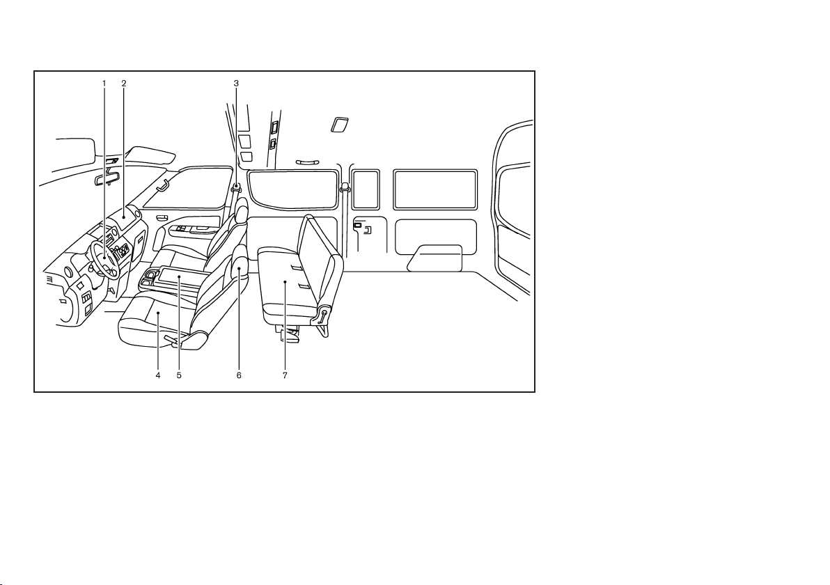
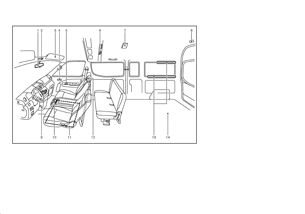
SEATS, SEAT BELTS AND SUPPLEMENTAL RESTRAINT SYSTEM
1. Driver’s supplemental front-impact air bag*
(Page 1-18)
2. Passenger’s supplemental front-impact air bag*
(P. 1-18)
3. Seat belts
— Three-point type seat belts (P.1-9)
— Two-point type seat belts (P.1-10)
— Pre-tensioner seat belt system* (P.1-21)
— Maintenance (P.1-11)
4. Front seats (P.1-2)
GUID-0AD5A92A-7204-41D2-AF19-1C528C0CC8B3
JVC0281X
5. Front center seat* (P.1-2)
6. Head restraints* (P.1-5)
7. Rear seats*
— Adjustment (P.1-3)
— Folding (P.1-4)
— Spare seats* (P.1-5)
— Child restraints (P.1-11)
*: if equipped
0-2 Illustrated table of contents
Black plate (7,1)
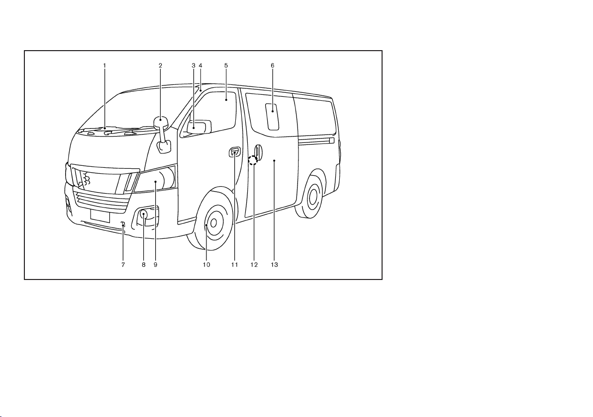
EXTERIOR FRONT
GUID-96E91208-A808-4682-A1F9-E034E237C0B8
1. Windshield wiper and washer
— Switch operation (P.2-17)
— Wiper blade replacement (P.8-17)
2. Front under mirror* (P.3-11)
3. Outside rearview mirrors (P.3-10)
4. Antenna (P.4-6)
5. Windows (P.2-20)
6. Sliding windows* (P.2-21)
7. Recovery hook (P.6-10)
11. Doors
— Keys (P.3-2)
— Door locks (P.3-3)
— Remote keyless entry system* (P.3-5)
— Security system* (P.3-6)
12. Child safety rear door locks* (P.3-4)
13. Sliding door(s)* (P. 3-3)
*: if equipped
JVC0260X
8. Fog lights*
— Switch operation (P.2-17)
— Bulb replacement (P.8-24)
9. Headlights/Turn signals/Clearance lights
— Switch operation (P.2-14)
— Bulb replacement (P.8-24)
10. Tires
— Tires and wheels (P.8-31)
— Flat tire (P.6-2)
— Specifications (P.9-6)
Illustrated table of contents 0-3
Black plate (8,1)
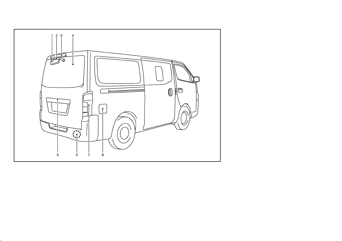
EXTERIOR REAR
GUID-4260CF6C-F4F0-45BD-9D0F-D436ABD2F57D
1. Rear under mirror* (P.3-11)
2. Rear window wiper and washer*
— Switch operation (P.2-17)
— Wiper blade replacement (P.8-17)
3. High-mounted stop light (P.8-24)
4. Rear window defogger* (P.2-19)
5. Back door (P.3-7)
6. Recovery hook (P.6-10)
7. Rear combination light (Bulb replacement)
(P.8-24)
JVC0261X
8. Fuel filler lid
— Operation (P.3-8)
— Fuel recommendation (P.9-2)
*: if equipped
0-4 Illustrated table of contents
Black plate (9,1)
PASSENGER COMPARTMENT
GUID-907C989D-6F62-4989-949E-2B7EDBD8A539
1. Inside rearview mirror (P.3-9)
2. Personal light (P.2-27)
3. Sun visor (P.2-26)
4. Inside lock knob (P.3-3)
5. Power windows* (P.2-20)
6. Rear cooler switch* (P.4-5)
7. Room light (P.2-27)
8. Luggage room light* (P.2-28)
9. Parking brake (Stick type)
— Operation (P.3-11)
JVC0280X
— Parking (P.5-12)
— Maintenance (P.8-14)
10. Console box (P.2-24)
11. Engine room inspection cover (P.8-5)
12. Partition pipe* (P. 2-25)
13. Luggage utility nut* (P. 2-25)
14. Spare tire (under the vehicle) (P. 6-4)
*: if equipped
Illustrated table of contents 0-5
Black plate (10,1)
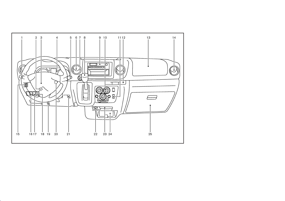
INSTRUMENT PANEL
GUID-9DBD6E0C-9224-4A31-B2B9-A1AD79715324
LEFT-HAND DRIVE (LHD) MODEL
1. Headlight, turn signal and fog light switch
— Headlights (P.2-14)
— Turn signals (P.2-16)
— Fog lights* (P.2-17)
2. Steering wheel lock lever (P. 3-9)
3. Steering wheel
— Power steering system (P.5-15)
— Horn (P.2-19)
GUID-8114E8A9-5D66-4C86-9359-C639072D123E
JVI0423X
— Driver’s supplemental front-impact air bag*
(P.1-18)
4. Meters and gauges (P.2-4)/Clock* (P.2-21)
5. Wiper and washer switch (P.2-17)
6. Center ventilator (P.4-2)
7. Hazard indicator flasher switch (P.2-19)
8. Selector lever (Automatic transmission model)
(P.5-8)/Shift lever (Manual transmission model)
(P.5-11)
9. Audio system* (P.4-6)
10. Heater and air conditioner* (P.4-2)
- Rear window defogger switch* (P.2-19)
11. Rear cooler switch* (P.4-5)
12. Cup holders (P2-24)
13. Passenger’s supplemental front-impact air bag*
(P.1-18) or Instrument upper box (P. 2-23)
14. Side ventilator (P.4-2)
15. Outside rearview mirror remote control switch*
(P.3-10)
16. Headlight aiming control* (P.2-15)
17. DPF switch (diesel engine model)* (P.5-4)
18. Heat switch (diesel engine model)* (P.4-5)
19. Fuel filler lid opener (P.3-8)
20. Ignition switch (P.5-6)
21. Snow mode switch (AT model) (P.5-12)
22. Power outlet* (P.2-22) or Cigarette lighter*
(P.2-22)
23. Ashtray (P.2-22)
24. Center lower pocket (P.2-23)
25. Glove box (P.2-23)
*: if equipped
0-6 Illustrated table of contents
Black plate (11,1)
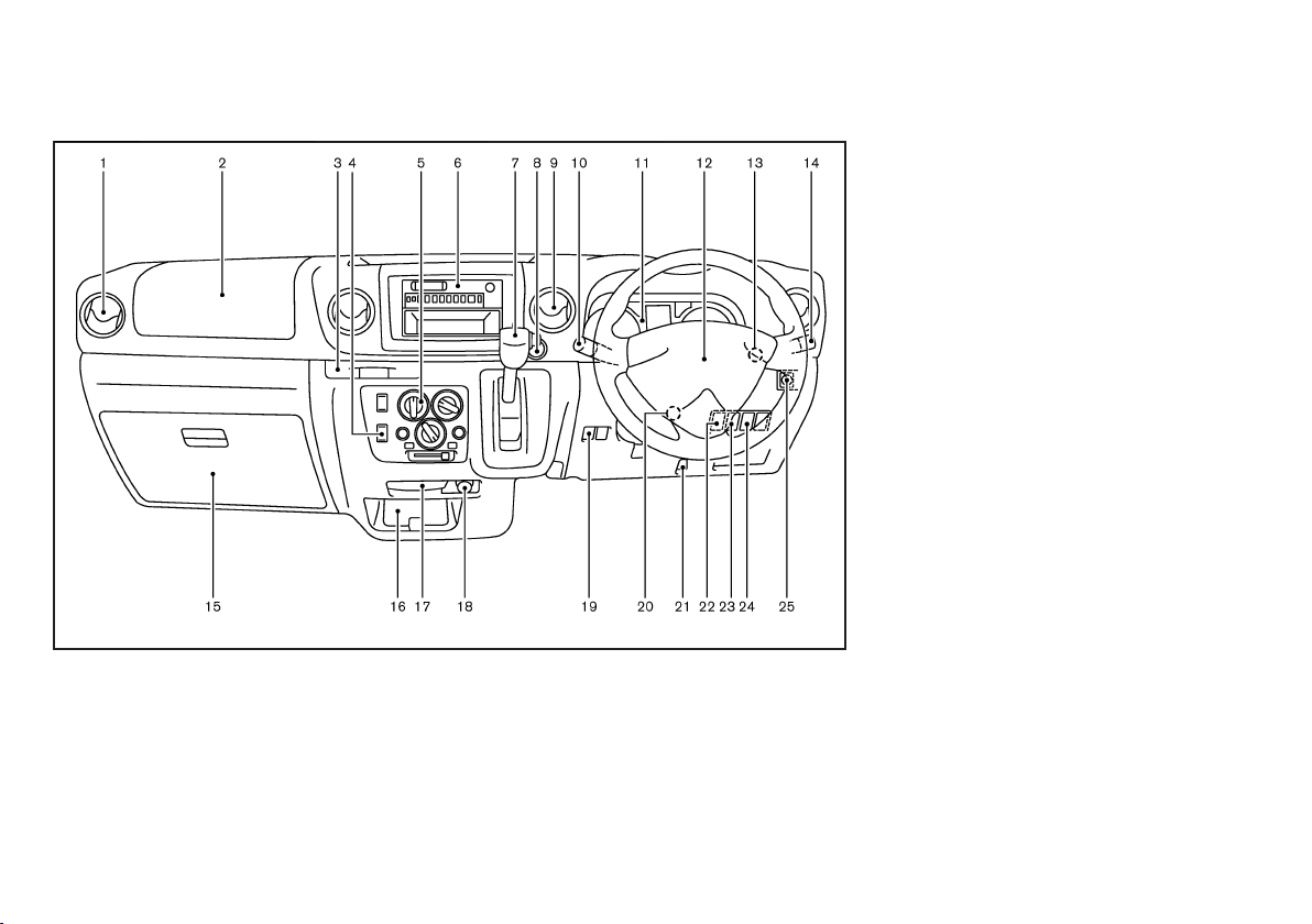
RIGHT-HAND DRIVE (RHD) MODEL
GUID-A7DAD5C6-ED35-4069-84C3-1B28D4E33CA5
1. Side ventilator (P.4-2)
2. Passenger’s supplemental front-impact air bag*
(P.1-18) or Instrument upper boxes (P. 2-23)
3. Cup holders (P2-24)
4. Rear cooler switch* (P.4-5)
5. Heater and air conditioner* (P.4-2)
- Rear window defogger switch* (P.2-19)
6. Audio system* (P.4-6)
JVI0422X
7. Selector lever (Automatic transmission model)
(P.5-8)/Shift lever (Manual transmission model)
(P.5-11)
8. Hazard indicator flasher switch (P.2-19)
9. Center ventilator (P.4-2)
10. Wiper and washer switch (P.2-17)
11. Meters and gauges (P.2-4)/Clock* (P.2-21)
12. Steering wheel
— Power steering system (P.5-15)
— Horn (P.2-19)
— Driver’s supplemental front-impact air bag*
(P.1-18)
13. Ignition switch (P.5-6)
14. Headlight, turn signal and fog light switch
— Headlights (P.2-14)
— Turn signals (P.2-16)
— Fog lights* (P.2-17)
15. Glove box (P.2-23)
16. Center lower pocket (P.2-23)
17. Ashtray (P.2-22)
18. Power outlet* (P.2-22) or Cigarette lighter*
(P.2-22)
19. Snow mode switch (AT model) (P.5-12)
20. Steering wheel lock lever (P. 3-9)
21. Fuel filler lid opener (P.3-8)
22. Heat switch (diesel engine model)* (P.4-5)
23. DPF switch (diesel engine model)* (P.5-4)
24. Headlight aiming control* (P.2-15)
25. Outside rearview mirror remote control switch*
(P.3-10)
*: if equipped
Illustrated table of contents 0-7
Black plate (12,1)
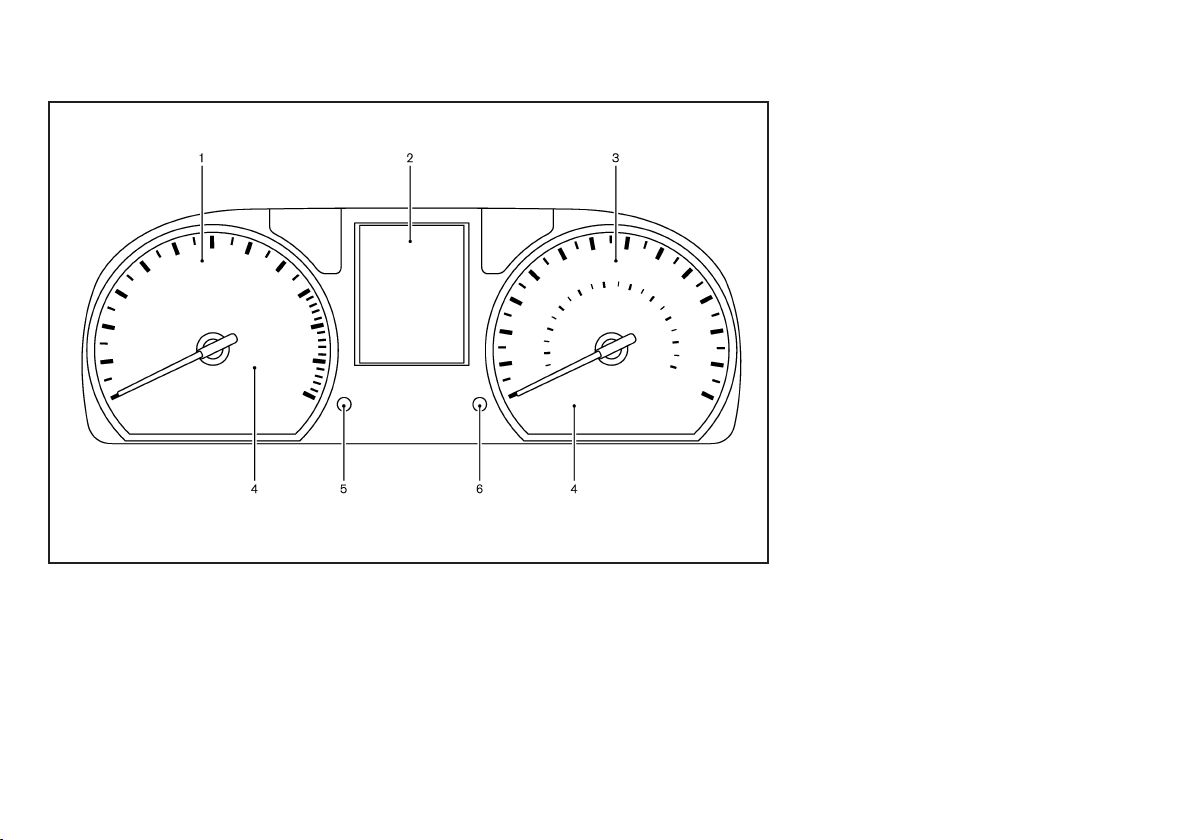
METERS AND GAUGES
GUID-23E66B22-C978-45BF-9695-9B860AFA3656
1. Tachometer (P.2-4)
2. Vehicle information display (P.2-5)
3. Speedometer (P.2-4)
4. Warning/indicator lights (P.2-10)
5. Instrument brightness control switch (P.2-9)/
Clock adjusting knob* (P.2-21)/Trip computer
mode switch (P.2-6 )
6. Trip computer mode switch (P.2-6)/Trip odometer reset switch (P.2-4)
*: if equipped
JVC0262X
0-8 Illustrated table of contents
Black plate (13,1)
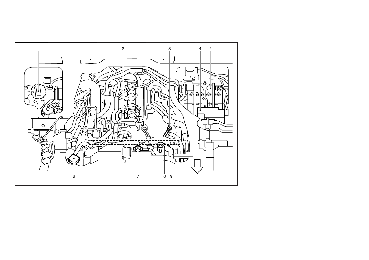
ENGINE COMPARTMENT
GUID-6E8BAB29-D775-444A-ACE0-EF69E5384399
QR20DE/QR25DE ENGINE MODEL
1. Air cleaner (P.8-16)
2. Engine oil filler cap (P.8-9)
3. Engine oil dipstick (P.8-8)
4. Fuse/fusible link box (P.8-22)
5. Battery (P.8-20)
6. Power steering fluid reservoir (P.8-16)
7. Radiator cap (P.8-7)
GUID-99BBD3CC-DC99-478A-B26A-23ED254697D4
JVC0279X
8. Engine coolant reservoir (P.8-8)
9. Drive belts (P. 8-13)
Illustrated table of contents 0-9
Black plate (14,1)
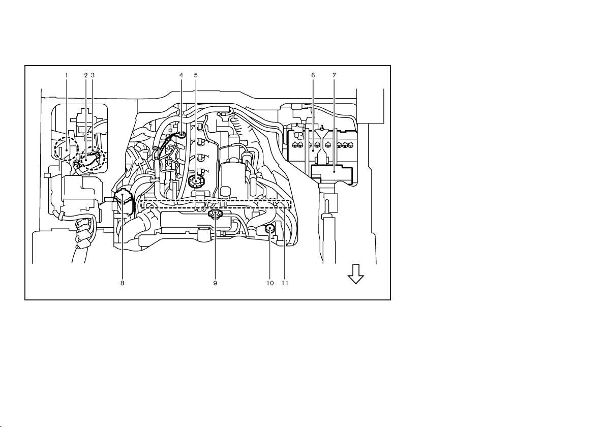
YD25DDTi ENGINE MODEL
1. Air cleaner (P.8-16)
2. Priming pump (P.8-11)
3. Fuel filter (P.8-11)
4. Engine oil dipstick (P.8-8)
5. Engine oil filler cap (P.8-9)
6. Battery (P.8-20)
7. Fuse/fusible link box (P.8-22)
8. Power steering fluid reservoir (P.8-16)
GUID-22D48CB5-0534-4F11-904E-D5747CD98EA7
JVM0124X
9. Radiator cap (P.8-7)
10. Engine coolant reservoir (P.8-8)
11. Drive belts (P. 8-13)
0-10 Illustrated table of contents

Black plate (15,1)
1 Safety — seats, seat belts and supplemental
restraint system
Seats ............................................................................................................... 1-2
Front seats .............................................................................................. 1-2
Rear seats (if equipped) ..................................................................... 1-3
Spare seat (if equipped) ..................................................................... 1-5
Head restraints (if equipped) ............................................................. 1-5
Seat belts ...................................................................................................... 1-6
Precautions on seat belt usage ........................................................ 1-6
Child safety ............................................................................................. 1-8
Pregnant women ................................................................................... 1-9
Injured persons ...................................................................................... 1-9
Center mark on seat belts (if equipped) ........................................ 1-9
Three-point type seat belts ................................................................ 1-9
Two-point type seat belts ................................................................ 1-10
Seat belt maintenance ...................................................................... 1-11
Child restraints .......................................................................................... 1-11
Precautions on child restraint usage ............................................ 1-11
Installation of child restraint system .............................................. 1-12
Supplemental Restraint System (SRS) (if equipped) ..................... 1-18
Precautions on Supplemental Restraint System (SRS) .......... 1-18
Supplemental air bag systems ....................................................... 1-20
Pre-tensioner seat belt system (if equipped) ............................. 1-21
Repair and replacement procedure .............................................. 1-21
Black plate (16,1)
SEATS
GUID-68C0D8A4-DFE7-43C8-A238-6E0083CB20BC
SSS0133A
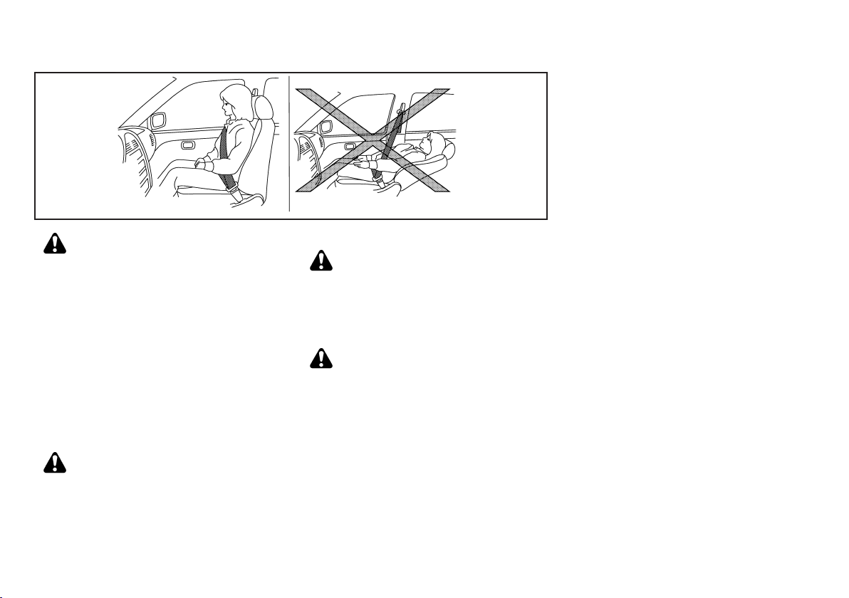
WARNING:
. Do not drive and/or ride in the vehicle with
the seatback reclined. This can be dangerous. The shoulder belt will not be properly
against the body. In an accident, you and
your passengers could be thrown into the
shoulder belt and receive neck or other
serious injuries. You and your passengers
could also slide under the lap belt and
receive serious injuries.
. For the most effective protection while the
vehicle is in motion, the seatback should be
upright. Always sit well back in the seat and
adjust the seat belt properly. (See “Seat
belts” (P.1-6).)
FRONT SEATS
Do not adjust the driver’s seat while driving so
that full attention may be given to vehicle
operation.
Manual seat adjustment
After adjusting a seat, gently shake the seat to
confirm that the seat is locked securely. If the
seat is not locked securely, it may move
suddenly and could cause loss of control of the
vehicle.
GUID-CB482850-66CB-4F95-85BA-0E93C9BBB14A
WARNING:
GUID-D0256135-124F-4E4D-BEFF-F799809D1F00
WARNING:
CAUTION:
When adjusting the seat positions, be sure not
to contact any moving parts to avoid possible
injuries and/or damages.
1-2 Safety — seats, seat belts and supplemental restraint system
Black plate (17,1)
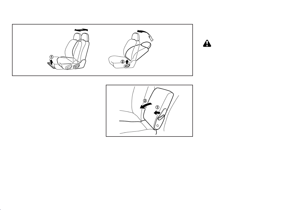
Forward and backward (if equipped):
1. Pull up the adjusting lever
2. Slide the seat to the desired position.
3. Release the adjusting lever to lock the seat in
position.
Reclining:
1. Pull up the adjusting lever
2. Tilt the seatback to the desired position.
3. Release the adjusting lever to lock the seatback in
position.
The reclining feature allows the adjustment of the
seatback for occupants of different sizes to help obtain
the proper seat belt fit. (See “Seat belts” (P.1-6).)
The seatback may be reclined to allow occupants to
rest when the vehicle is parked.
GUID-896AA31A-81D0-4E9B-81ED-1F58D53AA854
GUID-896AA31A-81D0-4E9B-81ED-1F58D53AA854
1
.
*
2
.
*
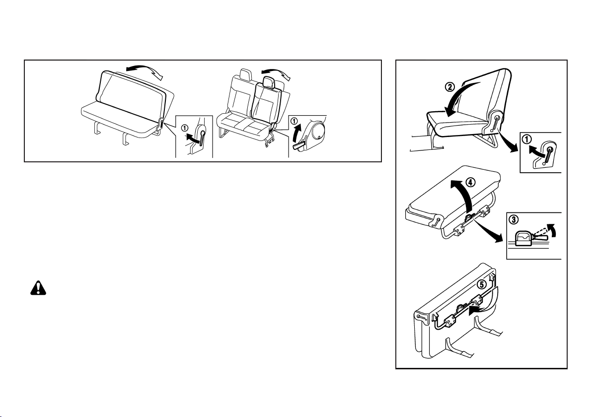
Folding front center seat (if equipped)
To fold the seatback, pull the lock lever
the seatback down
To raise the seatback, push the lock lever
the seatback up.
GUID-5EAA5990-885E-4607-8E29-55855DD1EFAF
1
2
.
*
*
1
*
JVR0093X
SPA1366A
and fold
and pull
REAR SEATS (if equipped)
Manual seat adjustment (if equipped)
GUID-5D1C7DE4-C5F4-4933-AB2B-2148F6939AE2
GUID-8D62EAAB-734E-4499-9D6E-BBC37E9D2219
WARNING:
After adjusting a seat, gently shake the seat to
confirm that the seat is locked securely. If the
seat is not locked securely, it may move
suddenly and could cause loss of control of the
vehicle.
Safety — seats, seat belts and supplemental restraint system 1-3
Black plate (18,1)
Reclining:
1. Pull the adjusting lever
GUID-896AA31A-81D0-4E9B-81ED-1F58D53AA854
1
.
*
2. Tilt the seatback to the desired position.
3. Release the adjusting lever to lock the seatback in
position.
The reclining feature allows the adjustment of the
seatback for occupants of different sizes to help obtain
the proper seat belt fit. (See “Seat belts” (P.1-6).)
The seatback may be reclined to allow occupants to
rest when the vehicle is parked.
Folding rear seats (if equipped)
GUID-1003FC14-CA26-43C4-A4DF-0663F6732C9D
WARNING:
. Be careful not to damage the seat belt while
folding the rear seats.
. Never allow anyone to ride in the luggage
area or on the rear seats when they are in
the folded position. Use of these areas by
passengers without proper restraints could
result in serious injury in an accident or
sudden stop.
JVR0090X
. Do not fold the rear seats while the vehicle is
moving.
. Do not fold the rear seats when occupants
are on the rear seat area or any luggage is
on the rear seats.
. Properly secure all luggage to help prevent it
from sliding or shifting. Do not place luggage higher than the seatbacks.
. When returning the seat to the original
position, be certain they are completely
secured in the latched position. If they are
not completely secured, passengers may be
injured in an accident or sudden stop.
. Securely store the removed head restraints
(if equipped) to prevent them from being
thrown around in case of a sudden stop or
accident.
. Head restraints (if equipped) should be
adjusted properly as they may provide significant protection against whiplash injury.
Always replace and adjust them properly if
they have been removed for any reason.
Type A:
GUID-896AA31A-81D0-4E9B-81ED-1F58D53AA854
JVR0092X
1-4 Safety — seats, seat belts and supplemental restraint system
Black plate (19,1)
1. Pull the lever
2. Pull the lock lever
cushion and fold it forward
3. Fold the rear leg
Type B:
1
*
GUID-896AA31A-81D0-4E9B-81ED-1F58D53AA854
and fold the seatback down
3
, and then lift the rear seat
*
5
*
4
.
*
of the seat downward.
2
.
*
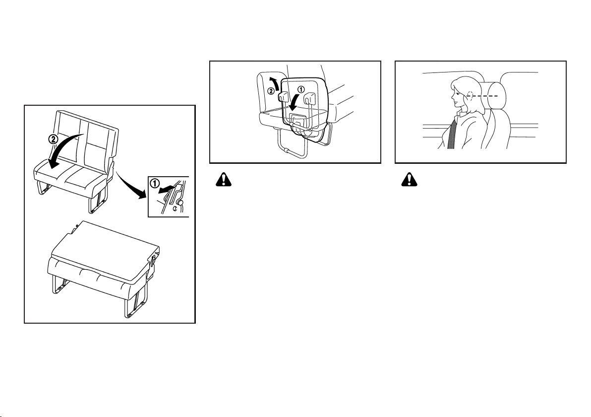
SPARE SEAT (if equipped)
GUID-32D41A4B-2FE0-4805-80E2-9D4D955CFDBB
HEAD RESTRAINTS (if equipped)
GUID-5897EF85-2586-4495-B906-92E4DD78AA40
Pull the lever
1
and fold the seatback down
*
JVR0091X
2
*
CAUTION:
. Operating the spare seat should be done
when the vehicle is stopped, and be careful
not to pinch your hands and feet to prevent
unexpected injuries.
. Be especially careful not to pinch your feet
between the seat leg and floor because the
seat leg automatically drops down when the
seat is opened.
1. Pull the spare seat downward to unfold
2. Raise the seatback up
.
2
.
*
Safety — seats, seat belts and supplemental restraint system 1-5
SPA1326
1
.
*
SSS0287
WARNING:
Do not drive and/or ride in the vehicle with the
head restraint removed. This can be dangerous.
Head restraints should be adjusted properly as
they may provide significant protection against
injury in an accident. Check the height after
someone else uses the seat.
The proper adjustment of the head restraint is as
illustrated.
Adjust the head restraint so that the head restraint’s
center is level with the center of the ears.
Black plate (20,1)
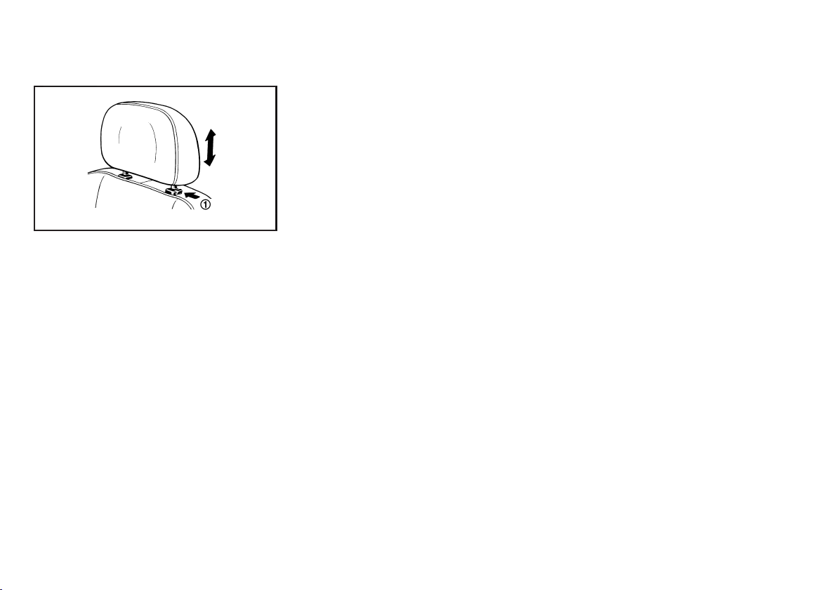
SEAT BELTS
Adjustment (if equipped)
1. Pull up the head restraint to raise to the proper
position.
2. Push in the lock knob
head restraint to lower to the proper position.
GUID-1A53EB51-62EF-4628-B88F-F41A2D2FE33F
SSS0288
1
and push down the
*
GUID-79F3FC3D-B95A-468D-9B36-0C04E9F410CE
PRECAUTIONS ON SEAT BELT USAGE
If you are wearing the seat belt properly adjusted and
sitting upright and well back in the seat, chances of
being injured or killed in an accident and/or the severity
of injury may be greatly reduced. NISSAN strongly
encourages you and all of your passengers to buckle
up every time you drive, even if your seating position
includes the supplemental air bag systems.
GUID-D6A96923-6676-40BF-ABA5-226510496F76
1-6 Safety — seats, seat belts and supplemental restraint system
Black plate (21,1)
SSS0134A
SSS0136A
SSS0014 SSS0016
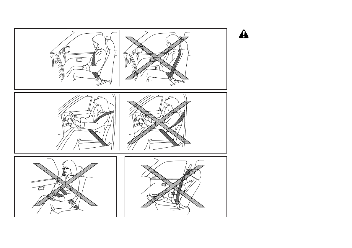
WARNING:
. Seatbelts are designed to bear upon the
bony structure of the body, and should be
worn low across the front of the pelvis or the
pelvis, chest and shoulders, as applicable;
wearing the lap section of the belt across
the abdominal area must be avoided. Serious injury may occur if a seat belt is not
worn properly.
. Position the lap belt as low and snug as
possible around the hips, not the waist. A
lap belt worn too high could increase the
risk of internal injuries in an accident.
. Do not allow more than one person to use
the same seat belt. Each belt assembly must
only be used by one occupant; it is dangerous to put a belt around a child being carried
on the occupant’s lap.
. Never carry more people in the vehicle than
there are seat belts.
. Never wear seat belts inside out. Belts
should not be worn with straps twisted.
Doing so may reduce their effectiveness.
. Seatbelts should be adjusted as firmly as
possible, consistent with comfort, to provide
the protection, for which they have been
designed. A slack belt will greatly reduce the
protection afforded to the wearer.
. Every person who drives or rides in this
vehicle should use a seat belt at all times.
Children should be properly restrained on
the rear seat and, if appropriate, in a child
restraint system.
Safety — seats, seat belts and supplemental restraint system 1-7
Black plate (22,1)
. Do not run the belt behind your back or
under your arm. Always route the shoulder
belt over your shoulder and across your
chest. The belt should be away from your
face and neck, but not falling off your
shoulder. Serious injury may occur if a seat
belt is not worn properly.
. No modifications or additions should be
made by the user which will either prevent
the seat belt adjusting devices from operating to remove slack, or prevent the seat belt
assembly from being adjusted to remove
slack.
. Care should be taken to avoid contamina-
tion of the webbing with polishes, oils and
chemicals, and particularly battery acid.
Cleaning may safely be carried out using
mild soap and water. The belt should be
replaced if webbing becomes frayed, contaminated or damaged.
. It is essential to replace the entire assembly
after it has been worn in a severe impact
even if damage to the assembly is not
obvious.
. All seat belt assemblies including retractors
and attaching hardware should be inspected
after any collision by a NISSAN dealer.
NISSAN recommends that all seat belt
assemblies in use during a collision be
replaced unless the collision was minor
and the belts show no damage and continue
to operate properly. Seat belt assemblies
not in use during a collision should also be
inspected and, when necessary, replaced if
either damage or improper operation is
noted.
. Once the pre-tensioner seat belt (if
equipped) has activated, it cannot be reused.
It must be replaced together with the
retractor. Contact a NISSAN dealer.
. Removal and installation of the pre-ten-
sioner seat belt system components (if
equipped) should be done by a NISSAN
dealer.
CHILD SAFETY
GUID-BAB8F5D8-D1DC-4C60-8080-5DAA6733F22B
WARNING:
. Infants and children need special protection.
The vehicle’s seat belts may not fit them
properly. The shoulder belt may come too
close to the face or neck. The lap belt may
not fit over their small hipbones. In an
accident, an improperly fitted seat belt could
cause serious or fatal injury.
. Always use an appropriate child restraint
system.
Children need adults to help protect them. They need
to be properly restrained. The proper restraint depends
on the child’s size.
Infants and small children
GUID-86834268-98A9-4C2A-A71B-B688289A27B9
SSS0099
NISSAN recommends that infants and small children
be seated in a child restraint system. You should
choose a child restraint system that fits your vehicle
and the child, and always follow the manufacturer’s
instructions for installation and use.
Large children
GUID-980A4C6C-98D5-4373-9C27-BCDADB902D30
WARNING:
. Never allow children to stand or kneel on
any seats.
. Never allow children in the cargo areas while
the vehicle is moving. A child could be
seriously injured in an accident or sudden
stop.
Children who are too large for a child restraint system
should be seated and restrained by the seat belts that
are provided.
If the child’s seating position has a shoulder belt that
fits close to the face or neck, the use of a booster seat
(commercially available) may help overcome this. The
booster seat should raise the child so that the shoulder
belt is properly positioned across the top, middle
1-8 Safety — seats, seat belts and supplemental restraint system
Black plate (23,1)
portion of the shoulder and the lap belt is low on the
hips. The booster seat should also fit the vehicle seat.
Once the child has grown so that the shoulder belt is
no longer on or near the face or neck of the child, use
the shoulder belt without the booster seat. In addition,
there are many types of child restraint systems
available for larger children that should be used for
maximum protection.
PREGNANT WOMEN
NISSAN recommends that pregnant women use seat
GUID-DC27FAF6-825C-4B88-A052-42F3885DCD35
belts. The seat belt should be worn snug, and always
position the lap belt as low as possible around the
hips, not the waist. Place the shoulder belt over your
shoulder and across your chest. Never run the lap/
shoulder belt over your abdominal area. Contact your
doctor for specific recommendations.
INJURED PERSONS
NISSAN recommends that injured persons use seat
GUID-385E24D4-B866-4986-9A3B-D5762B143C1D
belts. Contact your doctor for specific recommendations.
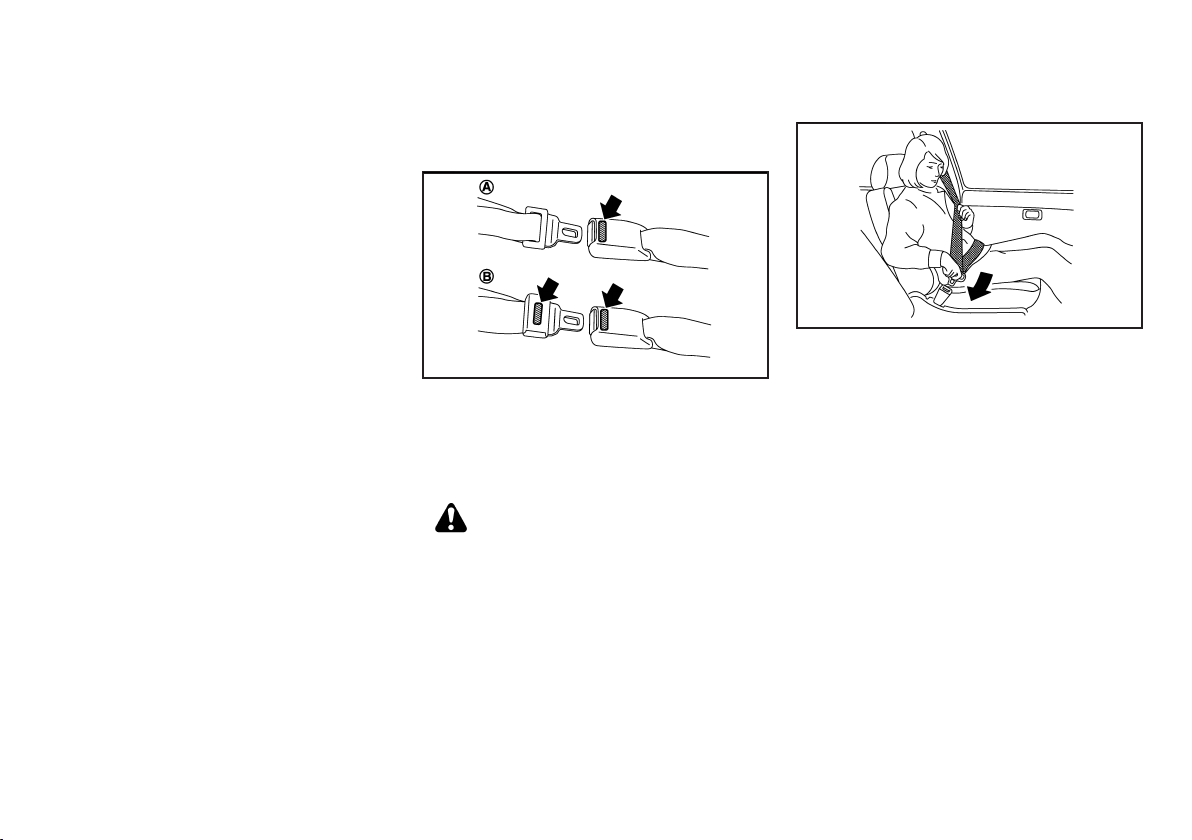
CENTER MARK ON SEAT BELTS (if
equipped)
Selecting correct set of seat belts
The center seat belt buckle
the tongue
The center seat belt tongue can be fastened only into
the center seat belt buckle.
THREE-POINT TYPE SEAT BELTS
. Every person who drives or rides in this
vehicle should use a seat belt at all times.
. The seatback should not be in a reclined
position any more than needed for comfort.
Seat belts are most effective when the
passenger sits well back and straight up in
the seat.
GUID-FA784FB1-F72D-477F-AB65-086061D689DE
GUID-E0B699CA-908C-4C24-B082-D6EE60516C9A
A
or both the buckle and
B
are identified by the CENTER mark.
*
GUID-DAA06BBB-2710-4996-909C-0598A94398C9
*
WARNING:
SSS0616
Fastening seat belts
GUID-9F35D48F-FF31-4561-B00F-4137ABF5BEFB
SSS0292
1. Adjust the seat. (See “Seats” (P.1-2).)
2. Slowly pull the seat belt out of the retractor and
insert the tongue into the buckle (marked CENTER for the center seat) until you hear and feel the
latch engage.
.
The retractor is designed to lock during a
sudden stop or on impact. A slow pulling
motion permits the seat belt to move, and
allows you some freedom of movement in
the seat.
.
If the seat belt cannot be pulled from its
fully retracted position, firmly pull the belt
and release it. Then smoothly pull the belt
out of the retractor.
Safety — seats, seat belts and supplemental restraint system 1-9
Black plate (24,1)
SSS0467
3. Position the lap belt portion low and snug on the
hips as shown.
4. Pull the shoulder belt portion toward the retractor
to take up extra slack. Be sure the shoulder belt is
routed over your shoulder and is snug across your
chest.
Unfastening seat belts
Push the button on the buckle. The seat belt
GUID-C810B8C8-7786-4920-B821-C51804AEB37E
automatically retracts.
Checking seat belt operation
Seat belt retractors are designed to lock seat belt
GUID-ACC4C337-C22B-417C-857A-4CACCCCBF3D4
movement:
. When the seat belt is pulled quickly from the
retractor.
. When the vehicle slows down rapidly.
To increase your confidence in the seat belts, check
the operation by grasping the shoulder belt and pulling
forward quickly. The retractor should lock and restrict
further belt movement. If the retractor does not lock
during this check, contact a NISSAN dealer immediately.
TWO-POINT TYPE SEAT BELTS
GUID-AADB00E0-0020-42C4-9D89-9969485CF2E2
WARNING:
. Every person who drives or rides in this
vehicle should use a seat belt at all times.
. The seatback should not be in a reclined
position any more than needed for comfort.
Seat belts are most effective when the
passenger sits well back and straight up in
the seat.
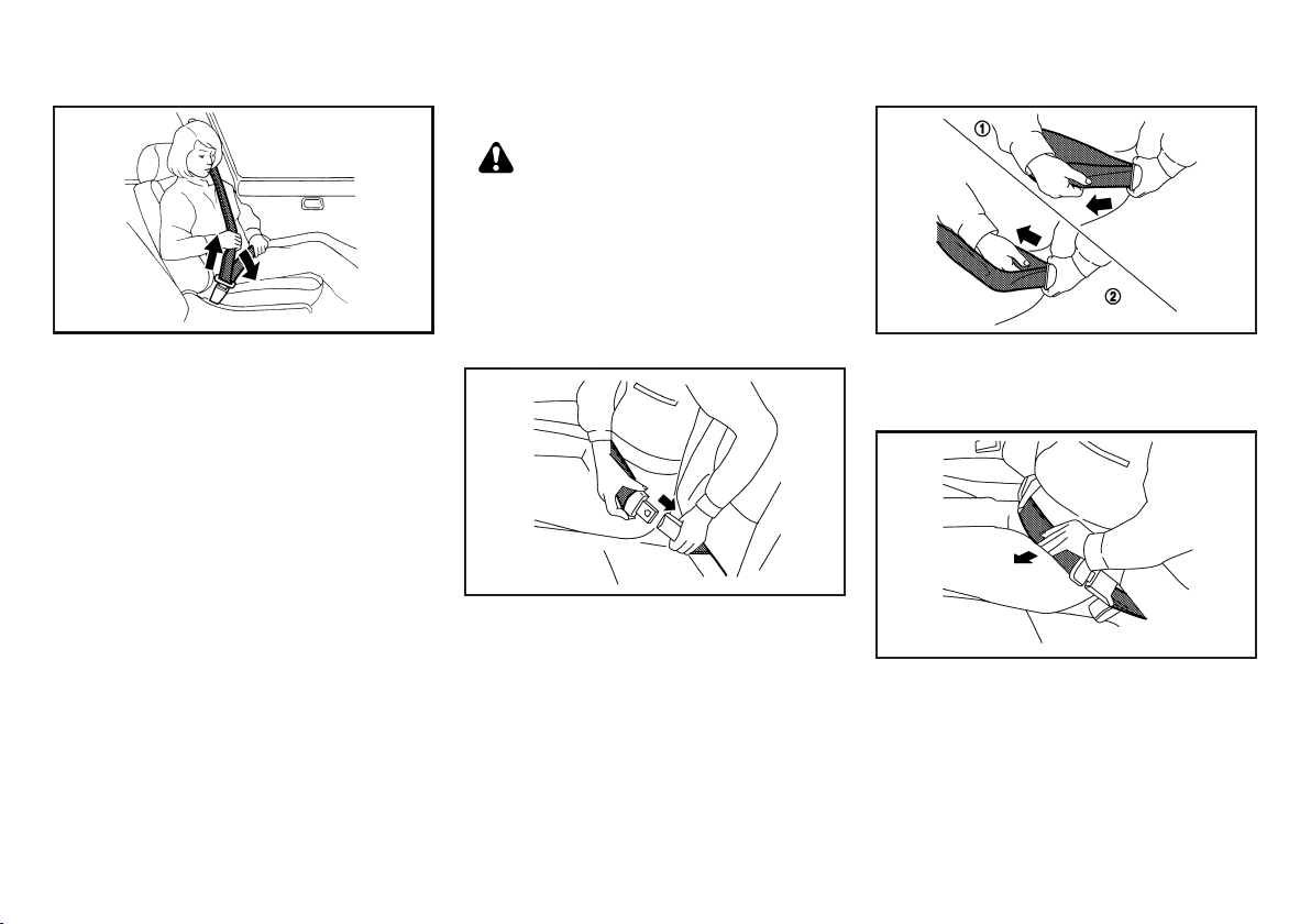
Fastening seat belts
GUID-9D26C2B4-4780-4F27-9491-45F5BFCB76E1
SSS0448
1. Insert the tongue into the buckle (marked CENTER for the center seat) until you hear and feel the
latch engage.
SSS0541
2. Adjust the seat belt length. To shorten, hold the
tongue and pull the upper belt as illustrated
1
*
To lengthen, hold the tongue and pull the under
belt as illustrated
2
.
*
SSS0450
3. Position the lap belt portion low and snug on the
hips as shown.
.
1-10 Safety — seats, seat belts and supplemental restraint system
Black plate (25,1)
CHILD RESTRAINTS
Unfastening seat belts
Push the button on the buckle.
GUID-61E0EDE0-643F-4A2A-A648-9F713131A996
Fasten the seat belts when not in use to prevent
them from being caught in the door.
SEAT BELT MAINTENANCE
Periodically check that the seat belt and all the metal
GUID-BF75E75C-F51C-4CA8-8B79-0873316F8DED
components, such as buckles, tongues, retractors,
flexible wires and anchors, work properly. If loose parts,
deterioration, cuts or other damage on the seat belt
webbing is found, the entire seat belt assembly should
be replaced.
If dirt builds up in the shoulder belt guide of the seat
belt anchors, the seat belts may retract slowly. Wipe
the shoulder belt guide with a clean, dry cloth.
To clean the seat belt webbing, apply a mild soap
solution or any solution recommended for cleaning
upholstery or carpet. Then wipe with a cloth and allow
the seat belts to dry in the shade. Do not allow the seat
belts to retract until they are completely dry.
GUID-CEB38DAC-43E4-44E2-AB63-FC4137FE3934
PRECAUTIONS ON CHILD RESTRAINT USAGE
. Infants and small children should never be
carried on your lap. It is not possible for even
the strongest adult to resist the forces of a
severe accident. The child could be crushed
between the adult and parts of the vehicle.
Also, it is dangerous to put a seat belt
around a child being carried on the occupant’s lap.
. Infants and children need special protection.
The vehicle’s seat belts may not fit them
properly. The shoulder belt may come too
close to the face or neck. The lap belt may
not fit over their small hip bones. In an
accident, an improperly fitting seat belt
could cause serious or fatal injury.
. Infants and small children should always be
placed in an appropriate child restraint
system while riding in the vehicle. Failure
to use a child restraint system can result in
serious injury or death.
GUID-C5C178B1-D6BE-4439-B6FE-3C8BC0EA2D26
SSS0099
WARNING:
Safety — seats, seat belts and supplemental restraint system 1-11
. Child restraint systems specially designed
for infants and small children are available
from several manufacturers. When selecting
any child restraint systems, place your child
in the child restraint system and check the
various adjustments to be sure that the child
restraint system is compatible with your
child. Always follow the manufacturer’s instructions for installation and use.
. NISSAN recommends that the child restraint
system be installed on the rear seat. According to accident statistics, children are safer
when properly restrained on the rear seat
rather than on the front seat.
. Follow all of the child restraint system
manufacturer’s instructions for installation
and use. When purchasing a child restraint
system, be sure to select one which will fit
your child and vehicle. It may not be possible
to properly install some types of child
restraint systems in your vehicle.
. For a front-facing child restraint system,
check to make sure the shoulder belt does
not fit close to child’s face or neck. If it does,
put the shoulder belt behind the child
restraint system.
. Never install a rear-facing child restraint
system on the front seat. An inflating
supplemental front-impact air bag (if
equipped) could seriously injure or kill your
child. A rear-facing child restraint system
must only be used on the rear seat.
. Adjustable seatbacks should be positioned
to fit a child restraint system, but as upright
as possible.
Black plate (26,1)
. If the seat belt in the position where a child
restraint system is installed requires a locking clip or another locking device and if it is
not used, injuries could result from a child
restraint system tipping over during normal
vehicle braking or cornering.
. After attaching a child restraint system, test
it before you place the child in it. Tilt it from
side to side. Try to tug it forward and check if
it is held securely in place. The child restraint
system should not move more than 25 mm (1
in). If the restraint is not secure, tighten the
belt as necessary, or install the restraint in
another seat and test it again.
. Check the child restraint system in your
vehicle to be sure that it is compatible with
the vehicle’s seat belt system.
. If a child restraint system is not anchored
properly, the risk of a child being injured in a
collision or a sudden stop greatly increases.
. Improper use of a child restraint system can
increase the risk or severity of injury for both
the child and other occupants in the vehicle.
. Always use an appropriate child restraint
system. An improperly installed child restraint system could lead to serious injury
or death in an accident.
. When the child restraint system is not in use,
keep it secured with a seat belt to prevent it
from being thrown around in case of a
sudden stop or accident.
NISSAN recommends that infants and small children
be seated in a child restraint system. You should
choose a child restraint system that fits your vehicle
and always follow the manufacturer’s instructions for
installation and use. In addition, there are many types
1-12 Safety — seats, seat belts and supplemental restraint system
of child restraint systems available for larger children
that should be used for maximum protection.
CAUTION:
Remember that a child restraint system left in a
closed vehicle can become very hot. Check the
seating surface and buckles before placing your
child in a child restraint system.
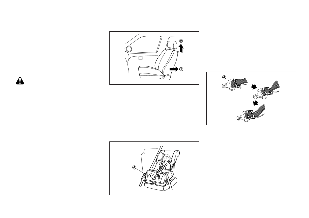
INSTALLATION OF CHILD RESTRAINT SYSTEM
GUID-43D48CD3-4654-4B0F-B5C0-7EAC8A35AF4C
Installation on rear seats - three-point type seat belts without automatic locking mode
The direction of the child restraint system
depends on the type of the child restraint system
and the size of the child.
Front-facing:
GUID-CAC0CBED-BC54-4913-B029-99607306BC66
WARNING:
GUID-896AA31A-81D0-4E9B-81ED-1F58D53AA854
SSS0374A
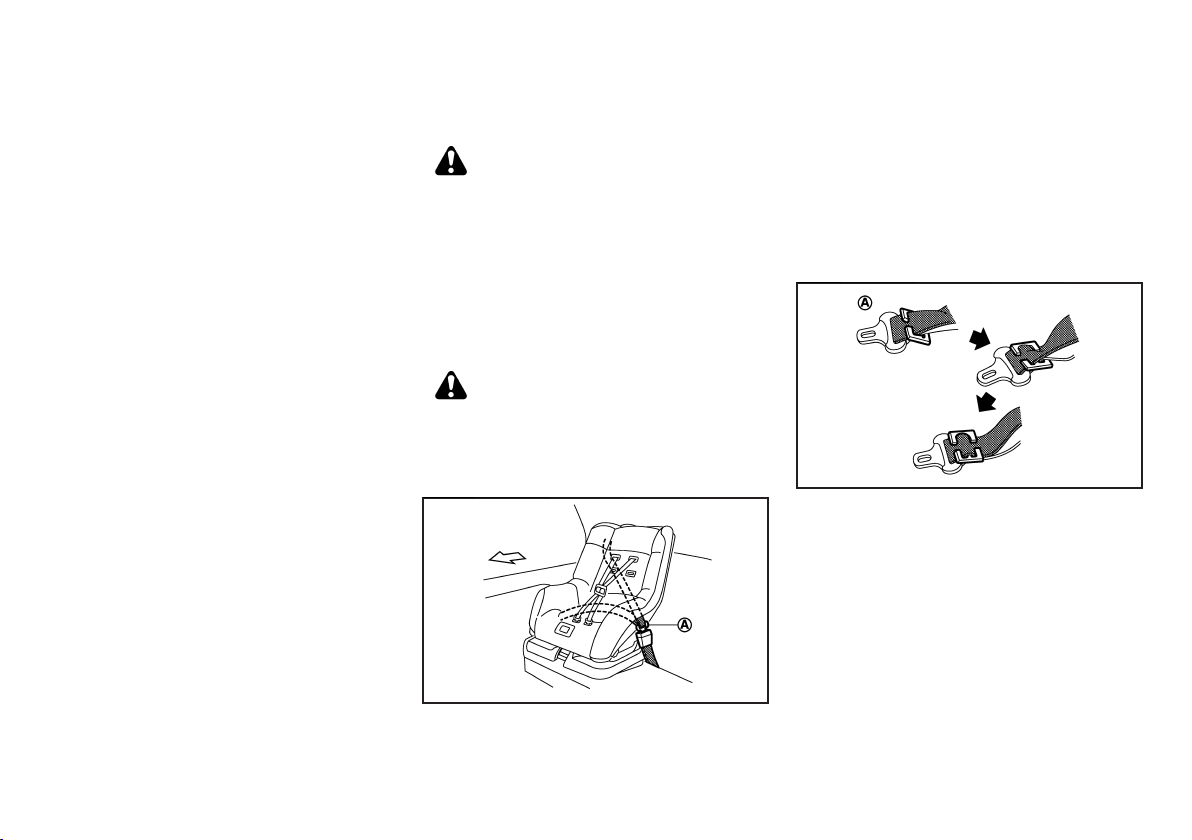
When you install a front-facing child restraint system
on the rear seat, follow these steps:
1. Position the front-facing child restraint system on
the rear seat.
Always follow the child restraint system manufacturer’s instructions for installation and use.
2. Route the seat belt tongue through the child
restraint system and insert it into the buckle until
you hear and feel the latch engage.
SSS0513
To prevent slack in the lap belt, it is necessary to
secure the shoulder belt in place with a locking
A
clip
. Use the locking clip or another locking
*
device attached to the child restraint system.
Be sure to follow the child restraint system
manufacturer’s instructions for belt routing.
3. Test the child restraint system before you place
the child in it. Tilt it from side to side. Try to tug it
forward and check if it is held securely in place.
4. Make sure that the child restraint system is
properly secured prior to each use.
Black plate (27,1)
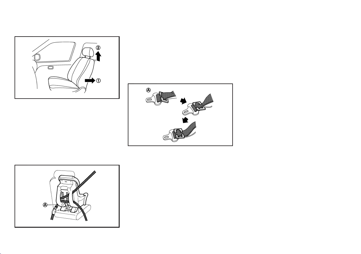
Rear-facing:
GUID-896AA31A-81D0-4E9B-81ED-1F58D53AA854
SSS0375A
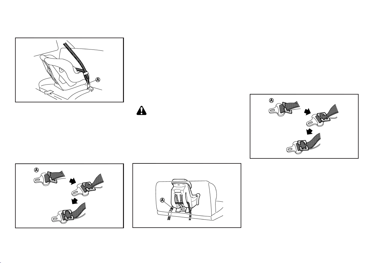
When you install a rear-facing child restraint system on
the rear seat, follow these steps:
1. Position the rear-facing child restraint system on
the rear seat.
Always follow the child restraint system manufacturer’s instructions for installation and use.
2. Route the seat belt tongue through the child
restraint system and insert it into the buckle until
you hear and feel the latch engage.
SSS0513
To prevent slack in the lap belt, it is necessary to
secure the shoulder belt in place with a locking
A
. Use the locking clip or another locking
clip
*
device attached to the child restraint system.
Be sure to follow the child restraint system
manufacturer’s instructions for belt routing.
3. Test the child restraint system before you place
the child in it. Tilt it from side to side. Try to tug it
forward and check if it is held securely in place.
4. Make sure that the child restraint system is
properly secured prior to each use.
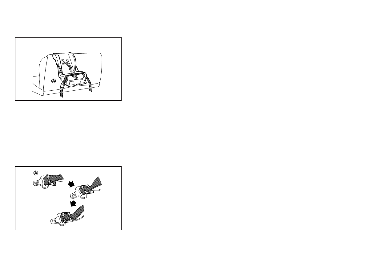
Installation on rear seats - two-point type seat belts
. NISSAN recommends that the child restraint
system be installed in a seat equipped with
the three-point type seat belt.
. The direction of the child restraint system
depends on the type of the child restraint
system and the size of the child.
Front-facing:
GUID-A7AC2B99-0E88-417D-B25B-E103A45CCFB5
WARNING:
GUID-896AA31A-81D0-4E9B-81ED-1F58D53AA854
SSS0512
If you must install a front-facing child restraint system
on the rear center seat equipped with the two-point
type seat belt, follow these steps:
1. Position the front-facing child restraint system on
the rear center seat.
Always follow the child restraint system manufacturer’s instructions for installation and use.
2. Route the seat belt tongue through the child
restraint system and insert it into the buckle until
you hear and feel the latch engage.
SSS0513
3. To prevent slack in the lap belt, it is necessary to
secure the lap belt in place with a locking clip
A
*
Use the locking clip or another locking device
attached to the child restraint system.
Be sure to follow the child restraint system
manufacturer’s instructions for belt routing.
4. Test the child restraint system before you place
the child in it. Tilt it from side to side. Try to tug it
forward and check if it is held securely in place.
5. Make sure that the child restraint system is
properly secured prior to each use.
.
Safety — seats, seat belts and supplemental restraint system 1-13
Black plate (28,1)
Rear-facing:
GUID-896AA31A-81D0-4E9B-81ED-1F58D53AA854
SSS0514
If you must install a rear-facing child restraint system
on the rear center seat equipped with the two-point
type seat belt, follow these steps:
1. Position the rear-facing child restraint system on
the rear center seat.
Always follow the child restraint system manufacturer’s instructions for installation and use.
2. Route the seat belt tongue through the child
restraint system and insert it into the buckle until
you hear and feel the latch engage.
3. To prevent slack in the lap belt, it is necessary to
secure the lap belt in place with a locking clip
A
*
Use the locking clip or another locking device
attached to the child restraint system.
Be sure to follow the child restraint system
manufacturer’s instructions for belt routing.
4. Test the child restraint system before you place
the child in it. Tilt it from side to side. Try to tug it
forward and check if it is held securely in place.
5. Make sure that the child restraint system is
properly secured prior to each use.
.
SSS0513
1-14 Safety — seats, seat belts and supplemental restraint system
Black plate (29,1)
Installation on front seat - with front passenger air bag
GUID-74D46FA9-902B-4727-8556-9052E3DBB2A6
Always follow the child restraint system manufacturer’s instructions for installation and use.
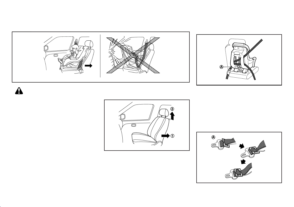
WARNING:
. Never install a rear-facing child restraint
system on the front seat. Inflating supplemental front-impact air bags inflate with
great force. A rear-facing child restraint
system could be struck by the supplemental
front-impact air bags in an accident and
could seriously injure or kill your child.
. Never install a child restraint with a top
tether strap on the front seat.
. NISSAN recommends that a child restraint
system be installed on the rear seat. However, if you must install a front-facing child
restraint system in the front passenger’s
seat, move the passenger’s seat to the
rearmost position.
. Child restraint systems for infants must be
used in the rear-facing direction and therefore must not be used on the front seat.
. Do not install a child restraint system in the
center position of the front bench seat. This
position is not suitable for the installation of
SSS0300A
a child restraint system.
Front-facing:
GUID-896AA31A-81D0-4E9B-81ED-1F58D53AA854
SSS0627
If you must install a front-facing child restraint system
on the front seat, follow these steps:
1. Move the seat to the rearmost position
2. Adjust the head restraint to its highest position
1
.
*
*
(if equipped).
3. Position the front-facing child restraint system on
the front passenger’s seat. It should be placed in
the front-facing direction only.
Safety — seats, seat belts and supplemental restraint system 1-15
4. Route the seat belt tongue through the child
restraint system and insert it into the buckle until
you hear and feel the latch engage.
To prevent slack in the lap belt, it is necessary to
secure the shoulder belt in place with a locking
A
clip
. Use the locking clip or another locking
*
device attached to the child restraint system.
Be sure to follow the child restraint system
manufacturer’s instructions for belt routing.
2
SSS0515
SSS0513
Black plate (30,1)
5. Slide the seat forward so that the seat belt fully
tightens the child restraint system.
6. Test the child restraint system before you place
the child in it. Tilt it from side to side. Try to tug it
forward and check if it is held securely in place.
7. Make sure that the child restraint system is
properly secured prior to each use.
Installation on front seat - without front passenger air bag
. NISSAN recommends that a child restraint
system be installed on the rear seat. However, if you must install a child restraint
system in the front passenger’s seat, move
the passenger’s seat to the rearmost position.
. Do not install a child restraint system in the
center position of the front bench seat. This
position is not suitable for the installation of
a child restraint system.
GUID-1860A488-C2FE-46A2-967E-D7CF96A62A10
WARNING:
Rear-facing:
If you must install a rear-facing child restraint system
on the front seat, follow these steps:
1. Move the seat to the rearmost position
equipped).
2. Adjust the head restraint to its highest position
(if equipped).
3. Position the rear-facing child restraint system on
the front passenger’s seat.
Always follow the child restraint system manufacturer’s instructions for installation and use.
GUID-896AA31A-81D0-4E9B-81ED-1F58D53AA854
SSS0627
1
*
*
4. Route the seat belt tongue through the child
restraint system and insert it into the buckle until
you hear and feel the latch engage.
To prevent slack in the lap belt, it is necessary to
secure the shoulder belt in place with a locking
A
clip
. Use the locking clip or another locking
*
device attached to the child restraint system.
Be sure to follow the child restraint system
manufacturer’s instructions for belt routing.
(if
2
5. Slide the seat forward so that the seat belt fully
tightens the child restraint system.
6. Test the child restraint system before you place
the child in it. Tilt it from side to side. Try to tug it
forward and check if it is held securely in place.
7. Make sure that the child restraint system is
properly secured prior to each use.
SSS0513
1-16 Safety — seats, seat belts and supplemental restraint system
SPA1706B
Black plate (31,1)
Front-facing:
If you must install a front-facing child restraint system
on the front seat, follow these steps:
1. Move the seat to the rearmost position
2. Adjust the head restraint to its highest position
(if equipped).
3. Position the front-facing child restraint system on
the front passenger’s seat. It should be placed in
the front-facing direction only.
Always follow the child restraint system manufacturer’s instructions for installation and use.
GUID-896AA31A-81D0-4E9B-81ED-1F58D53AA854
SSS0627
1
.
*
*
4. Route the seat belt tongue through the child
restraint system and insert it into the buckle until
you hear and feel the latch engage.
To prevent slack in the lap belt, it is necessary to
secure the shoulder belt in place with a locking
A
clip
. Use the locking clip or another locking
*
device attached to the child restraint system.
Be sure to follow the child restraint system
manufacturer’s instructions for belt routing.
2
5. Slide the seat forward so that the seat belt fully
tightens the child restraint system.
6. Test the child restraint system before you place
the child in it. Tilt it from side to side. Try to tug it
forward and check if it is held securely in place.
7. Make sure that the child restraint system is
properly secured prior to each use.
SSS0513
SSS0515
Safety — seats, seat belts and supplemental restraint system 1-17

Black plate (32,1)
SUPPLEMENTAL RESTRAINT
SYSTEM (SRS) (if equipped)
GUID-B40A7EEF-ADBD-4CF2-8E83-B0E688189B9C
PRECAUTIONS ON SUPPLEMENTAL RESTRAINT SYSTEM (SRS)
This Supplemental Restraint System (SRS) section
contains important information concerning the driver’s
and passenger’s supplemental front-impact air bags
and pre-tensioner seat belts.
Supplemental front-impact air bag system
This system can help cushion the impact force to the
head and chest area of the driver and/or front
passenger in certain frontal collisions. The supplemental front-impact air bag is designed to inflate on the
front where the vehicle is impacted.
The SRS is designed to supplement the accident
protection provided by the driver’s and passenger’s
seat belts and is not designed to substitute for them.
The SRS can help save lives and reduce serious
injuries. However, inflating air bags may cause abrasions or other injuries. Air bags do not provide
protection to the lower body. Seat belts should always
be correctly worn and the occupants should always be
seated a suitable distance away from the steering
wheel and instrument panel. (See “Seat belts” (P.1-6)).
The air bags inflate quickly in order to help protect the
occupants. The force of the air bags inflating can
increase the risk of injury if the occupants are too close
to, or are against, the air bag modules during inflation.
The air bags will deflate quickly after deployment.
The SRS operates only when the ignition switch
is in the “ON” or “START” position.
When the ignition switch is in the “ON” position,
the SRS air bag warning light illuminates for
about 7 seconds and then turns off. This
indicates that the SRS air bag system is operational. (See “SRS air bag warning light” (P.1-20).)
GUID-37754424-0563-4FED-9E65-7D5E1E6785F6
GUID-9925DA0D-9D65-4DAE-9460-8508E0AFA746
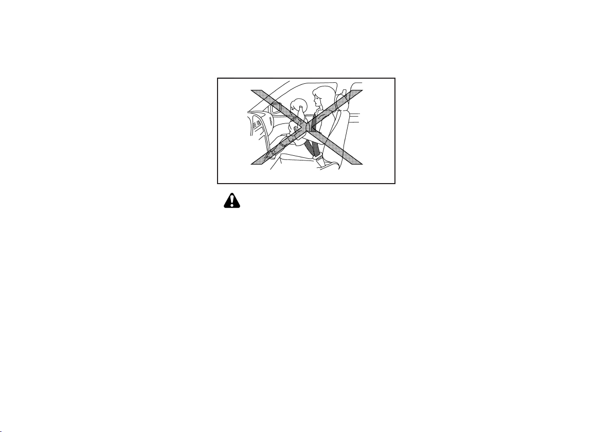
WARNING:
. The supplemental front-impact air bags
ordinarily will not inflate in the event of a
side impact, rear impact, rollover, or lower
severity frontal collision. Always wear the
seat belts to help reduce the risk or severity
of injury in accidents.
. The seat belts and the supplemental front-
impact air bags are most effective when you
are sitting well back and upright in the seat.
The front-impact air bags inflate with great
force. If you and your passengers are unrest-
SSS0131A
SSS0132A
rained, leaning forward, sitting sideways, or
out of position in any way, you and your
passengers are at greater risk of injury or
death in an accident. You and your passengers may also receive serious or fatal
injuries from the supplemental front-impact
air bag if you are up against it when it
inflates. Always sit back against the seatback and as far away as practical from the
steering wheel or instrument panel. Always
use the seat belts.
1-18 Safety — seats, seat belts and supplemental restraint system

Black plate (33,1)
SSS0006
SSS0009
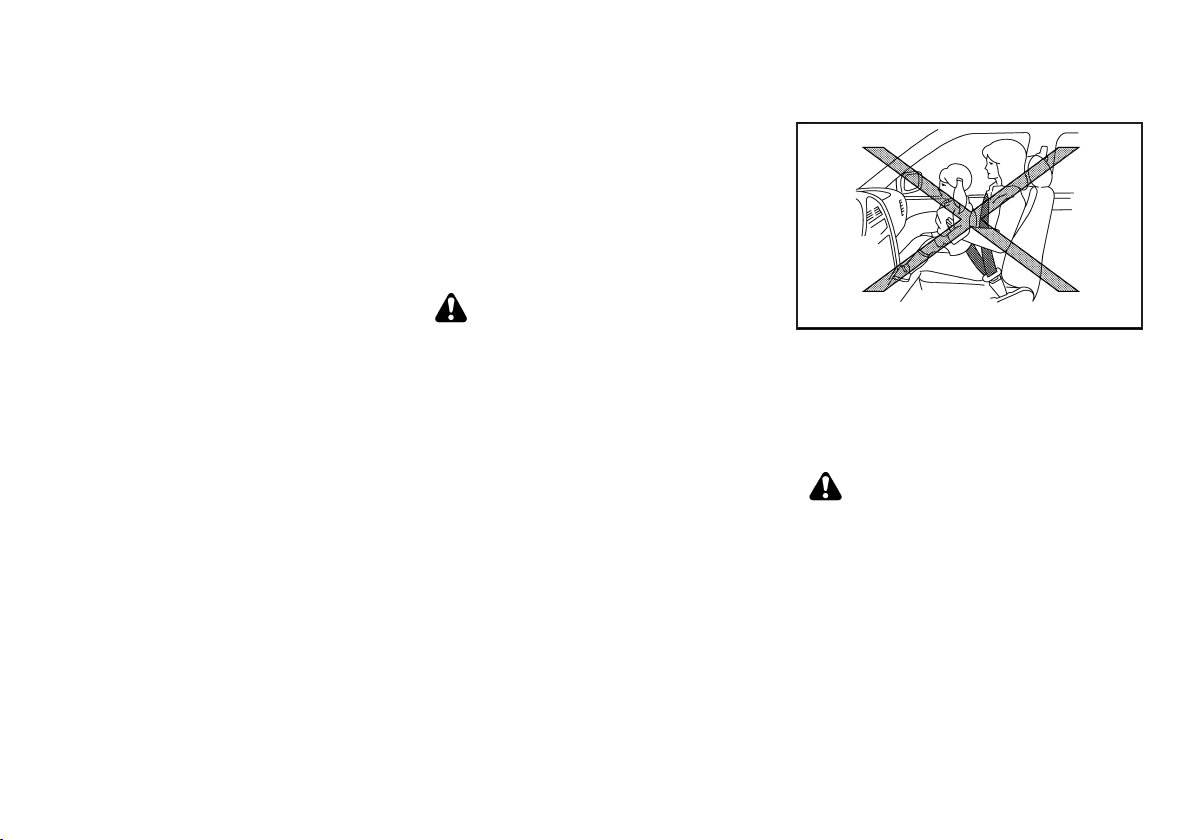
WARNING:
. Never let children ride unrestrained or
extend their hands or face out of the
window. Do not attempt to hold them in
your lap or arms. Some examples of dangerous riding positions are shown in the
illustrations.
. Children may be severely injured or killed
when the air bags inflate if they are not
properly restrained.
. Never install a rear-facing child restraint
system on the front seat if your vehicle is
equipped with the front passenger’s air bag
system. An inflating supplemental frontimpact air bag could seriously injure or kill
your child. (See “Child restraints” (P.1-11).)
SSS0007
SSS0008
Pre-tensioner seat belt system (if equipped)
The pre-tensioner system may activate with the
GUID-F0AD1D53-6823-42C7-B045-3B7103E040B9
supplemental air bag system in certain types of
SSS0099
collisions. Working with the seat belt retractor and
anchor, it helps tighten the seat belt the instant the
vehicle becomes involved in certain types of collisions,
helping to restrain front seat occupants. (See “Pretensioner seat belt system” (P.1-21).)
SSS0100
Safety — seats, seat belts and supplemental restraint system 1-19

Black plate (34,1)
Air bag warning labels
GUID-6BC401BB-F4F1-4CE8-9145-0C9E3ED1A002
SRS air bag warning light
GUID-341C3014-8BE7-4B0C-BEEA-44DD62BCC52E
SUPPLEMENTAL AIR BAG SYSTEMS
GUID-7FC8152B-77D4-422E-9C35-FF06BD6B5E74
JVR0081X
SRS air bag:
The warning label
GUID-896AA31A-81D0-4E9B-81ED-1F58D53AA854
1
is located on the surface of the
*
passenger’s sun visor.
SRS front-impact passenger air bag:
The warning label
GUID-896AA31A-81D0-4E9B-81ED-1F58D53AA854
2
(if equipped) is located on the
*
side of the passenger’s side instrument panel.
This label warns you not to fit a rear-facing child
restraint system on the front passenger seat as such a
restraint system used in this position could cause
serious injury to the infant in case of air bag
deployment during a collision.
In vehicles equipped with a front-impact passenger air
bag system, use a rear-facing child restraint system
only on the rear seats. “Extreme Hazard! Do not use a
rearward facing child restraint on a seat protected by
an airbag in front of it!"
When installing a child restraint system in your vehicle,
always follow the child restraint system manufacturer’s
instructions for installation.
For additional information, see “Child restraints” (P.1-
11).
The SRS air bag warning light, displaying in the
instrument panel, monitors the circuits of the supplemental front-impact air bag and pre-tensioner seat belt
systems. The circuits monitored by the SRS air bag
warning light are the diagnosis sensor unit, crash zone
sensor, front-impact air bag modules, pre-tensioner
seat belts and all related wiring.
When the ignition switch is in the “ON” or “START”
position, the SRS air bag warning light illuminates for
about 7 seconds and then turns off. This indicates that
the SRS air bag systems are operational.
If any of the following conditions occur, the air bag
and/or pre-tensioner seat belt systems need servicing:
. The SRS air bag warning light remains on after
approximately 7 seconds.
. The SRS air bag warning light flashes intermit-
tently.
. The SRS air bag warning light does not illuminate
at all.
Under these conditions, the supplemental front-impact
air bag or pre-tensioner seat belt systems may not
operate properly. They must be checked and repaired.
Contact a NISSAN dealer immediately.
1-20 Safety — seats, seat belts and supplemental restraint system
SPA1097
JVR0084X
1. Supplemental front-impact air bag modules (if
equipped)
2. Crash zone sensor (if equipped)
3. Supplemental air bag diagnosis sensor unit (if
equipped)
4. Pre-tensioner seat belt retractors (if equipped)
WARNING:
. Do not place any objects on the steering
wheel pad and on the instrument panel. Do
not place any objects between any occupants and the steering wheel pad and on the
instrument panel. Such objects may become
dangerous projectiles and cause injury if a
supplemental air bag inflates.
. Immediately after inflation, several supple-
mental air bag system components will be
hot. Do not touch them, or you may severely
burn yourself.
. No unauthorized changes should be made
to any components or wiring of the supplemental air bag systems. This is to prevent
accidental inflation of the supplemental air

Black plate (35,1)
bags or damage to the supplemental air bag
systems.
. Do not make unauthorized changes to your
vehicle’s electrical system, suspension system, front end structure, and side panels.
This could affect proper operation of the
supplemental air bag systems.
. Tampering with the supplemental air bag
systems may result in serious personal
injury. Tampering includes changes to the
steering wheel and the instrument panel by
placing materials over the steering wheel
pad and above, around or on the instrument
panel or by installing additional trim materials around the supplemental air bag systems.
. Work around and on the supplemental air
bag systems should be done by a NISSAN
dealer. The SRS wiring should not be
modified or disconnected. Unauthorized
electrical test equipment and probing devices should not be used on the supplemental air bag systems.
. The SRS wiring harness connectors are
yellow and/or orange for easy identification.
When the air bags inflate, a fairly loud noise may be
heard, followed by the release of smoke. This smoke is
not harmful and does not indicate a fire. Care should
be taken not to inhale it, as it may cause irritation and
choking. Those with a history of a breathing condition
should get fresh air promptly.
Supplemental front-impact air bag system
The driver’s supplemental front-impact air bag is
located at the center of the steering wheel. The
passenger’s supplemental front-impact air bag (if
equipped) is located at the instrument panel above
the glove box.
The supplemental front-impact air bag system is
designed to inflate in higher severity frontal collisions,
although it may inflate if the forces in another type of
collision are similar to those of a higher severity frontal
impact. It may not inflate in certain frontal collisions.
Vehicle damage (or lack of it) is not always an
indication of proper supplemental front-impact air
bag system operation.
GUID-10D19F42-D875-4BD1-910E-75A8CE2F4492
PRE-TENSIONER SEAT BELT SYSTEM (if
equipped)
. The pre-tensioner seat belt cannot be re-
used after activation. It must be replaced
together with the retractor and buckle as a
unit.
. If the vehicle becomes involved in a collision
but the pre-tensioner is not activated, be
sure to have the pre-tensioner system
checked and, if necessary, replaced by a
NISSAN dealer.
. No unauthorized changes should be made
to any components or wiring of the pretensioner seat belt system. This is to prevent
accidental activation of the pre-tensioner
seat belt or damage to the pre-tensioner
seat belt system.
GUID-1EF6D71E-7544-4260-A34C-C08560F5757D
WARNING:
. Work around or on the pre-tensioner seat
belt system should be done by a NISSAN
dealer. The SRS wiring should not be
modified or disconnected. Unauthorized
electrical test equipment and probing devices should not be used on the pretensioner seat belt system.
. If you need to dispose of the pre-tensioner
seat belt system, or scrap the vehicle,
contact a NISSAN dealer. Correct pre-tensioner disposal procedures are set forth in
the appropriate NISSAN Service Manual.
Incorrect disposal procedures could cause
personal injury.
The pre-tensioner is encased with the front seat belt’s
retractor and anchor. These seat belts are used the
same as conventional seat belts.
When the pre-tensioner seat belt activates, a fairly loud
noise may be heard, followed by the release of smoke.
This smoke is not harmful and does not indicate a fire.
Care should be taken not to inhale it, as it may cause
irritation and choking. Those with a history of a
breathing condition should get fresh air promptly.
REPAIR AND REPLACEMENT PROCEDURE
. Once the supplemental front-impact air bags
have been inflated, the air bag modules will
not function and must be replaced. The air
bag modules must be replaced by a NISSAN
dealer. The inflated air bag modules cannot
be repaired.
. The supplemental front-impact air bag sys-
tem should be inspected by a NISSAN dealer
GUID-1C1079A0-6942-4EA2-BCA3-C0257EB521C4
WARNING:
Safety — seats, seat belts and supplemental restraint system 1-21

Black plate (36,1)
if there is any damage to the front end
portion of the vehicle.
. If you need to dispose of the SRS or scrap
the vehicle, contact a NISSAN dealer. Correct disposal procedures are set forth in the
appropriate NISSAN Service Manual. Incorrect disposal procedures could cause personal injury.
The supplemental front-impact air bags and pretensioner seat belts are designed to activate on a
one-time-only basis. As a reminder, unless the SRS air
bag warning light is damaged, the SRS air bag warning
light remains illuminated after inflation has occurred.
The repair and replacement of the SRS should be
done only by a NISSAN dealer.
When maintenance work is required on the vehicle,
information about the supplemental front-impact air
bags, pre-tensioner seat belts and related parts should
be pointed out to the person performing the maintenance. The ignition switch should always be in the
“LOCK” position when working inside the vehicle.
1-22 Safety — seats, seat belts and supplemental restraint system

Black plate (37,1)
2 Instruments and controls
Instrument panel .......................................................................................... 2-2
Left-Hand Drive (LHD) model ............................................................ 2-2
Right-Hand Drive (RHD) model ........................................................ 2-3
Meters and gauges ..................................................................................... 2-4
Speedometer .......................................................................................... 2-4
Tachometer ............................................................................................. 2-4
Vehicle information display ................................................................. 2-5
Engine coolant temperature gauge .................................................. 2-5
Fuel gauge .............................................................................................. 2-5
Automatic Transmission (AT) position indicator (AT model) ........ 2-6
Upshift indicator (MT model) ............................................................. 2-6
Trip computer ......................................................................................... 2-6
Odometer ................................................................................................ 2-7
Displaying engine oil level information (diesel
engine model) ........................................................................................ 2-7
Clock (if equipped) .............................................................................. 2-9
Instrument brightness control ............................................................ 2-9
Warning/indicator lights and audible reminders ............................... 2-10
Checking bulbs .................................................................................. 2-11
Warning lights ..................................................................................... 2-11
Indicator lights .................................................................................... 2-13
Audible reminders .............................................................................. 2-14
Headlight and turn signal switch .......................................................... 2-14
Headlight switch ................................................................................ 2-14
Headlight aiming control (if equipped) ......................................... 2-15
Turn signal switch .............................................................................. 2-16
Fog light switch (if equipped) ............................................................... 2-17
Front fog lights ................................................................................... 2-17
Wiper and washer switch ...................................................................... 2-17
Windshield wiper and washer switch ........................................... 2-18
Rear window wiper and washer switch (if equipped) ............. 2-18
Defogger switch (if equipped) .............................................................. 2-19
Hazard indicator flasher switch ............................................................ 2-19
Horn ............................................................................................................ 2-19
Windows .................................................................................................... 2-20
Manual windows (if equipped) ..................................................... 2-20
Power windows (if equipped) ...................................................... 2-20
Sliding windows (if equipped) ..................................................... 2-21
Clock (if equipped) ................................................................................. 2-21
Adjusting time ................................................................................... 2-21
Ashtrays and cigarette lighter (if equipped) ..................................... 2-22
Ashtray ................................................................................................ 2-22
Cigarette lighter (if equipped) ...................................................... 2-22
Power outlet (if equipped) .................................................................... 2-22
Storages ..................................................................................................... 2-23
Glove box .......................................................................................... 2-23
Instrument upper boxes (if equipped) ........................................ 2-23
Center lower pocket ....................................................................... 2-23
Console box ...................................................................................... 2-24
Cup holders ...................................................................................... 2-24
Soft bottle holder ............................................................................. 2-24
Card holder (if equipped) ............................................................. 2-25
Luggage utility nut (if equipped) ................................................. 2-25
Partition (if equipped) ..................................................................... 2-25
Sun visors .................................................................................................. 2-26
Interior lights ............................................................................................. 2-27
Personal light .................................................................................... 2-27
Room light ......................................................................................... 2-27
Luggage room light (if equipped) ............................................... 2-28
>

Black plate (38,1)
INSTRUMENT PANEL
GUID-9FCA1C3B-D2E7-436F-96E9-F1C53EE9308F
LEFT-HAND DRIVE (LHD) MODEL
1. Headlight, turn signal and fog light switch
— Headlights
— Turn signals
— Fog lights*
2. Steering wheel lock lever
3. Steering wheel
— Power steering system
— Horn
GUID-5FAA14F8-0F9B-4847-8B7D-4B271375DAF4
JVI0423X
— Driver’s supplemental front-impact air bag*
4. Meters and gauges/Clock*
5. Wiper and washer switch
6. Center ventilator
7. Hazard indicator flasher switch
8. Selector lever (Automatic transmission model)/
Shift lever (Manual transmission model)
9. Audio system*
10. Heater and air conditioner*
- Rear window defogger switch*
11. Rear cooler switch*
12. Cup holders
13. Passenger’s supplemental front-impact air bag*
or Instrument upper box*
14. Side ventilator
15. Outside rearview mirror remote control switch*
16. Headlight aiming control*
17. DPF switch (diesel engine model)*
18. Heat switch (diesel engine model)*
19. Fuel filler lid opener*
20. Ignition switch
21. Snow mode switch (AT model)
22. Power outlet* or Cigarette lighter*
23. Ashtray
24. Center lower pocket
25. Glove box
*: if equipped
2-2 Instruments and controls

Black plate (39,1)
RIGHT-HAND DRIVE (RHD) MODEL
GUID-CD9E5369-B1BE-46C8-B34D-20A582D8A17F
1. Side ventilator
2. Passenger’s supplemental front-impact air bag*
or Instrument upper box*
3. Cup holders
4. Rear cooler switch*
5. Heater and air conditioner*
- Rear window defogger switch*
6. Audio system*
JVI0422X
7. Selector lever (Automatic transmission model)/
Shift lever (Manual transmission model)
8. Hazard indicator flasher switch
9. Center ventilator
10. Wiper and washer switch
11. Meters and gauges/Clock*
12. Steering wheel
— Power steering system
— Horn
— Driver’s supplemental front-impact air bag*
13. Ignition switch
14. Headlight, turn signal and fog light switch
— Headlights
— Turn signals
— Fog lights*
15. Glove box
16. Center lower pocket
17. Ashtray
18. Power outlet* or Cigarette lighter*
19. Snow mode switch (AT model)
20. Steering wheel lock lever
21. Fuel filler lid opener*
22. Heat switch (diesel engine model)*
23. DPF switch (diesel engine model)*
24. Headlight aiming control*
25. Outside rearview mirror remote control switch*
*: if equipped
Instruments and controls 2-3

Black plate (40,1)
METERS AND GAUGES
GUID-36B2BBCD-E11F-451D-969A-C754476347C1
1. Tachometer*
2. Vehicle information display
3. Speedometer*
4. Warning/indicator lights
5. Instrument brightness control switch/Clock adjusting knob/Trip computer mode switch
6. Trip computer mode switch/Trip odometer reset
switch
*: The needle indicators may move slightly after the
ignition switch is turned to the “LOCK” position. This is
not a malfunction.
JVC0262X
SPEEDOMETER
GUID-C407F3C6-C7D6-4A33-93FF-3811A094897B
JVI0399X
The speedometer indicates the vehicle speed.
TACHOMETER
GUID-4CF3A3B1-A21D-414E-8620-77AC231DCCC5
JVI0401X
The tachometer indicates the engine speed in revolutions per minute (rpm). Do not rev the engine into
the red zone
1
.
*
The red zone varies with models.
2-4 Instruments and controls

Black plate (41,1)
VEHICLE INFORMATION DISPLAY
GUID-9918B5E9-5232-444D-9B2F-6C13FFE7438D
ENGINE COOLANT TEMPERATURE GAUGE
GUID-EDAF3151-F04C-41B7-9B2F-B6E54E1705E0
FUEL GAUGE
GUID-D3C71D0F-E632-40A2-A03F-B539C38C9E35
JVI0410X
When the ignition switch is placed in the “ON”
position, the vehicle information display
the following information:
. Engine coolant temperature gauge
. Fuel gauge
. Automatic Transmission (AT) position indicator (AT
model)
. Upshift indicator (MT model)
. Trip computer
. Odometer
. Engine oil level information (diesel engine model)
. Clock (if equipped)
. Instrument brightness control
1
shows
*
JVI0402X
The engine coolant temperature gauge
the engine coolant temperature.
The engine coolant temperature is normal when the
gauge is within the zone
The engine coolant temperature will vary with the
outside air temperature and driving conditions.
2
shown in the illustration.
*
1
*
indicates
CAUTION:
. If the gauge indicates engine coolant tem-
perature near the hot (H) end of the normal
range, reduce vehicle speed to decrease
temperature.
. If the gauge is over the normal range, stop
the vehicle as soon as safely possible.
. If the engine is overheated, continued op-
eration of the vehicle may seriously damage
the engine. (See “If your vehicle overheats”
(P.6-9).)
JVI0403X
The fuel gauge
in the tank when the ignition switch is in the “ON”
position.
The gauge may move slightly during braking, turning,
accelerating, or going up and down hills due to
movement of fuel in the tank.
The low fuel warning light
the fuel level in the tank is getting low. Refuel as soon
as it is convenient, preferably before the gauge reads
0.
The arrow,
located on the right side of the vehicle.
1
indicates the approximate fuel level
*
2
illuminates when
*
, indicates that the fuel filler lid is
CAUTION:
Refuel before the gauge reads 0 (empty) .
There is a small reserve of fuel in the tank when the fuel
gauge reads 0 (empty).
Instruments and controls 2-5

Black plate (42,1)
AUTOMATIC TRANSMISSION (AT) POSITION INDICATOR (AT model)
The Automatic Transmission (AT) position indicator
indicates the selector lever position when the
ignition switch is in the “ON” position.
UPSHIFT INDICATOR (MT model)
When the ignition switch is in the ON position and upshifting is required, the upshift indicator display comes
on.
The upshift indicator
number of set revolutions continues for at least 0.1
seconds. It is possible to change the rpm setting within
the upshift indicator setting mode. See 2-6.
TRIP COMPUTER
The switch for the trip computer is located on the
meter panel.
When the ignition switch is placed in the “ON”
position, modes of the trip computer can be selected
by pushing the trip computer mode switch
Each time the trip computer mode switch
pushed, the display will change as follows:
(TRIP A ? TRIP B) ? Current fuel consumption ?
GUID-BF8F4CF3-6EEE-4FCC-8CA2-AAB149CD67BB
GUID-66836702-9B1D-484A-A417-EFCF906A15C1
is displayed when the
GUID-09A031BD-A6C8-4809-BB98-F6BF821E5BAD
JVI0405X
A
.
*
A
*
Average fuel consumption ? Distance to empty (dte)
? Upshift indicator setting (for MT model) ? (TRIP A)
Current fuel consumption
The current fuel consumption mode shows the current
fuel consumption.
Push the trip computer mode switch
fuel consumption display between L/100 km and km/L
(if equipped).
Average fuel consumption (L/100 km or mpg)
The average fuel consumption mode shows the
average fuel consumption since the last reset. Resetting is done by pushing the trip computer mode switch
A
for longer than 1 second.
*
The display is updated every 30 seconds. At about the
first 500 m (1/3 miles) after a reset, the display shows
“----”.
Push the trip computer mode switch
fuel consumption display between L/100 km and km/L
(if equipped).
Distance to empty (dte — km or miles)
The distance to empty (dte) mode provides you with an
estimation of the distance that can be driven before
refueling. The dte is constantly being calculated, based
on the amount of fuel in the fuel tank and the actual fuel
consumption.
The display is updated every 30 seconds.
The dte mode includes a low range warning feature:
when the fuel level is low, the dte mode is automatically
selected and the digits and the low fuel warning light
blink in order to draw the driver’s attention. Push
the trip computer mode switch
is
mode that was selected before the warning occurred.
When the fuel level drops even lower, the dte display
GUID-A08472C7-6CE2-40C7-8C4D-91986C70F8F3
B
*
GUID-F46204B2-43B2-4507-9328-908D43C94E48
B
*
GUID-D9EE1A84-A11F-4E2D-83F5-FD27CB66745D
A
to return to the
*
to toggle the
to toggle the
will change to “----”.
. If the amount of fuel added is small, the
display just before the ignition switch is
turned off may continue to be displayed.
. When driving uphill or rounding curves, the
fuel in the tank shifts, which may momentarily change the display.
Upshift indicator setting (MT model)
When this mode is turned on, the upshift indicator
shows the driver the timing to shift into a higher
gear. The use of the upshift indicator will help you to
upshift at a constant engine speed (RPM) from any
gear.
When the engine speed reaches the set speed, the
upshift indicator will flash.
To set the upshift indicator setting value:
1. Push and hold the trip computer mode switch
A
*
display will start flashing.
2. While the display is flashing, turn the trip computer
mode switch
figure can be set at intervals of 100 rpm and
between 1,000 and 4,000 rpm (diesel engine
model), or between 1,000 and 6,000 rpm (gasoline engine model).
3. Push the trip computer mode switch
the setting mode.
If no further action is taken, the display will return to the
upshift indicator setting display.
GUID-3E68A98B-EB95-494D-9863-521EFC7674CA
GUID-896AA31A-81D0-4E9B-81ED-1F58D53AA854
, to set the engine speed (RPM). The setting
B
to set the desired RPM. The
*
A
to exit
*
2-6 Instruments and controls

Black plate (43,1)
Resetting displays
When the average fuel consumption, average speed,
elapsed time or TRIP B is displayed, push the trip
computer mode switch
The display of average fuel consumption and trip
odometer (TRIP B only) will be reset at the same time.
ODOMETER
Odometer/Twin trip odometer (Type A)
The odometer/twin trip odometer is displayed when
the ignition switch is in the “ON” position.
The odometer
vehicle has been driven.
The twin trip odometer
individual trips.
Changing trip odometer display:
Push the trip odometer reset switch
display as follows:
TRIP A ? TRIP B ? Trip computer mode ?TRIP A
For trip computer information, see 2-6.
GUID-5FCC97D2-3597-4E51-B5A7-9FEA428C91F0
A
for longer than 3 seconds.
*
GUID-941C33C0-7D82-4B9E-8215-8D21DA7FD135
JVI0400X
GUID-B3EC23E0-4766-4D35-BE07-41A71FEBDE61
1
displays the total distance the
*
2
displays the distance of
*
GUID-896AA31A-81D0-4E9B-81ED-1F58D53AA854
3
to change the
*
Resetting trip odometer:
Push the trip odometer reset switch
mately 1 second to reset the trip odometer to zero.
Odometer/Twin trip odometer (Type B)
The odometer/twin trip odometer is displayed when
the ignition switch is in the “ON” position.
The digital clock
The odometer
vehicle has been driven.
The twin trip odometer
individual trips.
Changing trip odometer display:
Push the trip odometer reset switch
display as follows:
ODO ? TRIP A ? TRIP B ? Trip computer mode ?
ODO
For trip computer information, see 2-6.
Resetting trip odometer:
Push the trip odometer reset switch
mately 1 second to reset the trip odometer to zero.
GUID-896AA31A-81D0-4E9B-81ED-1F58D53AA854
GUID-46F3F34F-7808-4689-90FA-981A7EF12B89
1
displays the time.
*
2
displays the total distance the
*
2
displays the distance of
*
GUID-896AA31A-81D0-4E9B-81ED-1F58D53AA854
GUID-896AA31A-81D0-4E9B-81ED-1F58D53AA854
3
for approxi-
*
3
to change the
*
3
for approxi-
*
DISPLAYING ENGINE OIL LEVEL INFORMATION (diesel engine model)
GUID-E02A9233-CAC6-418F-A55A-EA72AEFF6B1A
JVI0405X
Instruments and controls 2-7

Black plate (44,1)
JVI0438X
When the ignition switch is in the “ON” position,
engine oil information is displayed.
Engine oil information informs you of the distance to oil
change, oil level indication and oil level sensor
malfunctions.
1. Distance to oil change
For model without Diesel Particulate Filter
(DPF):
When the ignition switch is turned to the ON position,
the distance to oil change is displayed.
For model equipped with Diesel Particulate
Filter (DPF):
When the ignition switch is turned to the ON position,
the distance to oil change is displayed if the distance
to oil change is less than 1,500 km (940 miles).
GUID-FDBC8737-3B4C-4221-8FFA-8D1D4E8244BD
2. Oil replacement indicator (model without Diesel Particulate Filter (DPF))
If the oil replacement indicator is displayed,
change the engine oil as soon as possible.
Operating your vehicle with oil that has deteriorated can damage the engine.
When the distance to oil change information showing
zero (0) or less is displayed: When the ignition switch
is turned to the ON position, a wrench symbol blinks
and the distance to oil change information showing
zero (0) is displayed for approximately 5 seconds.
Setting distance to oil change:
The distance to oil change interval can be adjusted or
disabled using the trip computer mode switch
Refer to the separate maintenance booklet for the
appropriate distance to oil change interval.
GUID-8426767C-23DE-4CE4-9245-AF8027D72132
CAUTION:
GUID-896AA31A-81D0-4E9B-81ED-1F58D53AA854
A
.
*
To adjust oil change interval:
1. Push and hold the trip computer mode switch
for more than 3 seconds while the wrench symbol
and distance to oil change information are
displayed.
If adjusting the distance from zero (0): Push and
hold the trip computer mode switch
than 3 seconds within 5 seconds of turning the
ignition switch to the “ON” position.
The wrench symbol
start flashing.
2. While the display is flashing, push and hold the
trip computer mode switch
seconds to enter the adjustment mode.
If adjusting the distance from zero (0): Push the
trip computer mode switch
distance to oil change will be restored.
3. Turn the trip computer mode switch
wise or counterclockwise to increase or decrease
the interval. Each turn increases or decreases the
interval by 1,000 km (500 miles) .
If no further action is taken, the display will switch to
the oil level indication and the new interval will be set.
To cancel oil change reminder:
1. Push and hold the trip computer mode switch
for more than 3 seconds while the wrench symbol
and distance to oil change information are
displayed.
The wrench symbol
start flashing.
2. While the display is flashing, push the trip
computer mode switch
adjustment mode.
A
*
*
and the distance will
A
for more than 3
*
A
. The default
*
and the distance will
again to enter the
A
B
*
*
for more
clock-
*
A
A
2-8 Instruments and controls

Black plate (45,1)
3. Turn the trip computer mode switch
clockwise until the interval reads 0.
If no further action is taken, the display will switch to
the oil level indication and the oil change reminder is
cancelled.
No wrench symbol or distance will be displayed when
the ignition switch is turned to the “ON” position. To
reactivate the reminder, set the distance to oil change
interval to a value above zero (0).
A
*
counter-
2. Oil replacement indicator (model equipped
with Diesel Particulate Filter (DPF))
If the oil replacement indicator is displayed,
change the engine oil as soon as possible.
Operating your vehicle with oil that has deteriorated can damage the engine.
When the distance to oil change information showing
zero (0) is displayed: When the ignition switch is
turned to the ON position, a wrench symbol blinks and
the distance to oil change information showing zero (0)
is displayed for approximately 5 seconds
When the set mileage approaches, the engine oil
replacement indicator will appear on the display. After
the oil is changed, reset the distance to oil change.
To reset the distance to oil change, push and hold the
trip odometer reset switch
seconds while the distance to oil change or oil
replacement indicator is displayed.
The distance to oil change interval cannot be adjusted
manually. The distance to oil change interval is set
automatically.
GUID-B33CBF28-1517-493C-B536-339AE6963564
CAUTION:
A
for more than 3
*
3. Oil level display
When the ignition switch is pushed to the “ON”
position, the engine oil status is displayed.
4. Low level reminder
If the low level indicator is displayed, the engine oil
level is low. In this case, check the level using the oil
dipstick. (See “Engine oil” (P.8-8) .)
GUID-635138D6-1BA7-4FDE-9663-B22868F47082
GUID-39E684B3-7816-4161-907A-DC9B5BD584D9
CAUTION:
The oil level should be checked regularly using
the engine oil dipstick. Operating the vehicle
with an insufficient amount of oil can damage
the engine and such damage is not covered by
the warranty.
(See “Engine oil” (P.8-8).)
5. Oil level sensor warning
If the oil sensor warning is displayed, the engine oil
level sensor may be malfunctioning. Contact a NISSAN
dealer immediately.
GUID-9AC3201B-B49E-425D-9B90-EADDE6374F09
CAUTION:
. Even if "Oil Good" appears on the engine oil
maintenance display, be sure to replace the
engine oil when the engine oil level gauge
shows that the oil level exceeds the Hi level
by approximately 10 mm (0.4 inch) because
the oil performance has decreased.
. Always reset the oil control system after
replacing the engine oil.
CLOCK (if equipped)
For clock adjustment, see “Clock” (P.2-21).
INSTRUMENT BRIGHTNESS CONTROL
The instrument brightness control operates when the
ignition switch is in the “ON” position and the headlight
switch is in either the
Turn the instrument brightness control switch
adjust the brightness of the meter. The brightness
indicator
information display when the control is turned.
When the brightness level reaches the maximum or
minimum, a beep will sound.
GUID-84B6F0E3-CDAE-4466-811D-F42B1C2F7B44
GUID-7CCCFBFC-A4FA-4DDC-BC50-681D229575D7
or position.
B
will be shown briefly in the vehicle
*
JVI0404X
A
*
to
Instruments and controls 2-9

Black plate (46,1)
WARNING/INDICATOR LIGHTS AND AUDIBLE REMINDERS
GUID-C318C751-4CF3-413B-A515-7ABDB40AA27F
Anti-lock Braking System (ABS) warning
light*
Brake warning light Seat belt warning light Malfunction Indicator Light (MIL)
Charge warning light Speed [120 km/h (75 MPH)] warning light* Overdrive off indicator light (AT model)
Diesel Particulate Filter (DPF) warning light
(if equipped for diesel engine model)*
Door open warning light
Engine oil pressure warning light Front fog lights indicator light* *: if equipped
Low washer fluid warning light
Low fuel warning light High beam indicator light
Supplemental Restraint System (SRS) air
bag warning light*
Water-in-fuel-filter warning light (diesel engine model)
Glow plug indicator light (diesel engine
model)
Security indicator light*
Turn signals/hazard indicator lights
2-10 Instruments and controls

Black plate (47,1)
CHECKING BULBS
With all doors closed, apply the parking brake, fasten
GUID-494FB3B3-70EC-412A-8322-911C910D5FD5
the seat belts and turn the ignition switch to the “ON”
position without starting the engine. The following
lights will illuminate:
, , ,
If equipped, the following lights will illuminate briefly
and then turn off:
, , , ,
If any lights fail to illuminate, it may indicate a burnedout bulb or an open circuit in the electrical system.
Have the system checked, and if necessary repaired,
by a NISSAN dealer promptly.
WARNING LIGHTS
GUID-CBC0E608-E05A-481E-BE9D-C21FE123A93A
Anti-lock Braking System (ABS)
warning light (if equipped)
When the ignition switch is in the “ON” position, the
Anti-lock Braking System (ABS) warning light illuminates and then turns off. This indicates the ABS is
operational.
If the ABS warning light illuminates while the engine is
running, or while driving, it may indicate the ABS is not
functioning properly. Have the system checked by a
NISSAN dealer.
If an ABS malfunction occurs, the anti-lock function is
turned off. The brake system then operates normally,
but without anti-lock assistance. (See “Brake system”
(P.5-15).)
GUID-FF26EA6A-9AC2-438C-9C00-35F3B3AFA308
Brake warning light
GUID-93522551-B7F5-409C-9CCF-4871BB4CD273
WARNING:
. If the brake fluid level is below the minimum
mark on the brake fluid reservoir, do not
drive the vehicle until the brake system has
been checked by a NISSAN dealer.
. Even if you judge it to be safe, have your
vehicle towed because driving it could be
dangerous.
. Depressing the brake pedal without the
engine running and/or with a low brake
fluid level could increase the stopping distance and require greater pedal travel distance and effort.
The brake warning light indicates the parking brake
system operation and a low brake fluid level of the
brake system.
Parking brake warning indicator:
When the ignition switch is in the “ON” position, and
GUID-896AA31A-81D0-4E9B-81ED-1F58D53AA854
the parking brake is applied, the brake warning light
illuminates. When the parking brake is released while
the engine is running, the brake warning light turns off.
If the parking brake is not fully released, the brake
warning light remains on. Be sure that the brake
warning light has turned off before driving. (See
“Parking brake” (P.3-11).)
Low brake fluid warning indicator:
If the brake warning light illuminates while the engine is
GUID-896AA31A-81D0-4E9B-81ED-1F58D53AA854
running, or while driving, and the parking brake is
released, it may indicate the brake fluid level is low.
When the brake warning light illuminates while driving,
stop the vehicle safely as soon as possible. Stop the
engine and check the brake fluid level. If the brake fluid
level is at the minimum mark, add brake fluid as
necessary. (See “Brake and clutch fluid” (P.8-15).)
If the brake fluid level is sufficient, have the brake
system checked by a NISSAN dealer promptly.
Charge warning light
When the ignition switch is in the “ON” position, the
GUID-8416D213-E270-49FB-9110-7F164D1BF337
charge warning light illuminates. After starting the
engine, the charge warning light turns off. This
indicates the charging system is operational.
If the charge warning light illuminates while the engine
is running, or while driving, it may indicate the charging
system is not functioning properly and may need
servicing.
When the charge warning light illuminates while
driving, stop the vehicle safely as soon as possible.
Stop the engine and check the alternator belt. If the
alternator belt is loose, broken or missing, the charging
system needs repair. (See “Drive belts” (P.8-13).)
If the alternator belt appears to be functioning correctly
but the charge warning light remains illuminated, have
the charging system checked by a NISSAN dealer
promptly.
CAUTION:
Do not continue driving if the alternator belt is
loose, broken or missing.
Instruments and controls 2-11

Black plate (48,1)
Diesel Particulate Filter (DPF) warning
light (if equipped for diesel engine model)
When the ignition switch is in the “ON” position, the
Diesel Particulate Filter (DPF) warning light illuminates
and then turns off. This indicates that the system is
operational.
When the DPF warning light illuminates, it indicates
that particulate matter accumulated in the DPF has
reached the specified limit amount.
Park the vehicle safely off the road, away from traffic
and in an open area. Press the diesel particulate filter
regeneration switch to start the regeneration process.
Do not park the vehicle over flammable materials such as dry grass, waste paper or rags, as
they may burn easily.
NOTE:
. Although it is possible to keep driving for
approximately 400 km even if the light
illuminates, perform the regeneration process as soon as possible.
. The DPF warning light may turn off when the
vehicle is driven at speeds above 80 km/h
(50 MPH) for approximately 20 minutes.
Because the period of time required for the
light to turn off varies depending on the
conditions, park the vehicle safely off the
road, away from traffic and in an open area
as soon as possible. Then perform the
regeneration process.
For more details of this system, see “Diesel Particulate
Filter (DPF) (if equipped for diesel engine model)” (P.5-
4).
GUID-0FCBD301-C420-4AC7-937C-10660A0D3698
WARNING:
Door open warning light
When the ignition switch is in the “ON” position, the
door open warning light illuminates if any of the doors
are open or not closed securely.
When the ignition switch is in the “ON” position, the
engine oil pressure warning light illuminates. After
starting the engine, the engine oil pressure warning
light turns off. This indicates that the oil pressure
sensors in the engine are operational.
If the engine oil pressure warning light illuminates or
blinks while the engine is running, it may indicate that
the engine oil pressure is low.
Stop the vehicle safely as soon as possible. Stop the
engine immediately and call a NISSAN dealer.
GUID-7326B3AB-17D9-4C23-9489-45D7258CB53A
Engine oil pressure warning light
GUID-FE83F48D-C232-4862-B416-526F7F275202
CAUTION:
. Running the engine with the engine oil
pressure warning light illuminated could
cause serious damage to the engine.
. The engine oil pressure warning light is not
designed to indicate a low oil level. The oil
level should be checked using the dipstick.
(See “Engine oil” (P.8-8).)
Low fuel warning light (if equipped)
The low fuel warning light illuminates when the fuel
level in the tank is getting low. Refuel as soon as it is
convenient, preferably before the fuel gauge reaches
the empty (E) position.
GUID-2598C12C-1289-4954-B832-88263DF13DC4
There will be a small reserve of fuel remaining in
the tank when the fuel gauge reaches the empty
(E) position.
Low washer fluid warning light
The low washer fluid warning light illuminates when the
washer tank fluid is at a low level. Add washer fluid as
necessary. (See “Window washer fluid” (P.8-18).)
When the ignition switch is in the “ON” position, the
seat belt warning light illuminates. The light will
continue to illuminate until the driver’s seat belt is
fastened. (See “Seat belts” (P.1-6).)
When the vehicle speed exceeds 15 km/h (10 MPH),
the light will blink and the chime will sound unless the
driver’s seat belt is securely fastened. The chime will
continue to sound for about 90 seconds until the seat
belt is fastened.
GUID-DCB8CC86-B8E9-4C3C-A19F-33195BFE76E8
Seat belt warning light
GUID-F04D4B19-7BC6-44D2-9B8E-55F771EA7BE6
Speed [120 km/h (75 MPH)] warning
light (if equipped)
This light blinks when the vehicle speed goes over
approximately 120 km/h (75 MPH). Be sure to observe
the speed limit in the area where you are driving.
GUID-0B8812FB-5246-42E5-BAA5-B740B8E7684A
Supplemental Restraint System (SRS)
air bag warning light (if equipped)
When the ignition switch is in the “ON” or “START”
position, the Supplemental Restraint System (SRS) air
bag warning light illuminates for about 7 seconds and
then turns off. This indicates the SRS air bag system is
operational.
If any of the following conditions occur, the SRS air
bag system and pre-tensioner seat belt need servicing.
Have the system checked, and if necessary repaired,
GUID-F4A77B1D-04FC-4DE5-B4D9-73D14CB0480F
2-12 Instruments and controls

Black plate (49,1)
by a NISSAN dealer promptly.
. The SRS air bag warning light remains illuminated
after about 7 seconds.
. The SRS air bag warning light flashes intermit-
tently.
. The SRS air bag warning light does not come on
at all.
Unless checked and repaired, the SRS air bag system
and/or pre-tensioner seat belt may not function
properly. (See “Supplemental Restraint System
(SRS)” (P.1-18).)
Water-in-fuel-filter warning light (diesel
engine model)
If the water-in-fuel-filter warning light illuminates while
the engine is running, drain the water from the fuel filter
promptly. (See “Fuel filter and sedimentor (diesel
engine model)” (P.8-11).)
Continuing vehicle operation without properly
draining could cause serious damage to the
engine.
INDICATOR LIGHTS
GUID-71CFBFB4-BB0C-4774-989E-DF1F23B54E14
CAUTION:
GUID-D769A635-0535-4D9F-B46F-BB918221B90A
Front fog lights indicator light (if
equipped)
The front fog lights indicator light illuminates when the
front fog lights are on. (See “Fog light switch” (P.2-
17))
GUID-5C89FB31-C672-4F51-A743-BB6E355D5FD1
Glow plug indicator light (diesel engine
model)
When the ignition switch is in the “ON” position, the
glow plug indicator light illuminates and turns off after
the glow plugs have warmed up.
If the glow plug indicator light stays illuminated after
the glow plugs have sufficiently warmed up, it may
indicate the glow plug system is not functioning
properly and may need servicing. Have the system
checked, and if necessary repaired, by a NISSAN
dealer.
High beam indicator light
The high beam indicator light illuminates when the
headlight high beam is on. The indicator turns off when
the low beam is selected. (See “Headlight and turn
signal switch” (P.2-14).)
Malfunction Indicator Light (MIL)
When the ignition switch is in the “ON” position, the
Malfunction Indicator Light illuminates. After starting
the engine, the light turns off. This indicates that the
engine control system is operational.
If the Malfunction Indicator Light illuminates or blinks (if
equipped) while the engine is running, it may indicate
that the engine control system is not functioning
properly and may need servicing. Have the system
checked, and if necessary repaired, by a NISSAN
dealer promptly.
GUID-EA251E54-4270-425B-B8D3-EC2135FFB718
GUID-30FD8BD4-1425-46EA-B373-9A003AF7E329
GUID-B4FE46AE-C2B4-43D2-8B49-E127E6B8E6C2
CAUTION:
Continuing vehicle operation without properly
draining could cause serious damage to the
engine.
Malfunction indicator on steady:
An engine control system malfunction has been
GUID-896AA31A-81D0-4E9B-81ED-1F58D53AA854
detected. Have the vehicle checked, and if necessary
repaired, by a NISSAN dealer promptly. You do not
need to have your vehicle towed to the dealer.
Malfunction indicator blinking (if equipped):
An engine misfire has been detected which may
GUID-896AA31A-81D0-4E9B-81ED-1F58D53AA854
damage the engine control system. Have the vehicle
checked, and if necessary repaired, by a NISSAN
dealer promptly.
Precautions:
To reduce or avoid possible damage to the engine
GUID-896AA31A-81D0-4E9B-81ED-1F58D53AA854
control system when the Malfunction Indicator Light
illuminates or blinks:
. Avoid driving at speeds above 70 km/h (43 MPH).
. Avoid sudden acceleration or deceleration.
. Avoid going up steep uphill grades.
. Avoid carrying or towing unnecessary loads.
CAUTION:
. Continuing vehicle operation without proper
servicing of the engine control system could
lead to poor driveability, reduced fuel economy, and damage to the engine control
system, which may affect the vehicle’s
warranty coverage.
. Incorrect setting of the engine control sys-
tem may lead to non-compliance of local
Instruments and controls 2-13

Black plate (50,1)
and national emission laws and regulations.
Overdrive off indicator light (AT model)
The overdrive off indicator light illuminates when the
GUID-CAB20368-DE8A-4B34-BCB7-336E2111D72D
Overdrive is turned off. (See “Driving with Automatic
Transmission (AT)” (P.5-8).)
Security indicator light (if equipped)
The security indicator light blinks whenever the ignition
GUID-E6BBC08A-1CB9-4B86-8E79-BA65315AD73F
switch is in the “ACC”, “OFF” or “LOCK” position. This
function indicates that the theft warning system
equipped on the vehicle is operational.
If the theft warning system is malfunctioning, this light
will remain on while the ignition switch is in the “ON”
position. (See “Security system” (P.3-6) for additional
information.)
Turn signals/hazard indicator lights
The turn signals/hazard indicator lights blink when the
GUID-770F6299-9516-48B2-AD45-F0C60A129643
turn signal switch or hazard indicator flasher switch is
turned on. (See “Headlight and turn signal switch”
(P.2-14) or “Hazard indicator flasher switch” (P.2-19).)
AUDIBLE REMINDERS
Brake pad wear warning
The disc brake pads have audible wear warnings.
GUID-10673240-E8AA-4A39-A57D-09DFFE4B4530
GUID-7C739796-1FBA-4FFB-9E9D-B366C8B160EC
When a brake pad requires replacement, it will make a
high pitched scraping sound when the vehicle is in
motion whether or not the foot brake pedal is
depressed.
Have the system checked, and if necessary repaired,
by a NISSAN dealer promptly. (See “Brakes” (P.8-
14).)
Reverse warning buzzer (if equipped)
A buzzer will sound outside of the vehicle to warn the
GUID-7654F161-21AF-4A78-B0A9-4534E4954103
people around the vehicle when the shift lever is
moved to the “R” (Reverse) position.
Key reminder chime
The chime will sound if the driver’s side door is opened
GUID-354F2291-0FCD-4CFF-AB43-4825EF4D9A25
while the key is left in the ignition switch and the
ignition switch is in the “ACC”, “OFF” or “LOCK”
position.
Be sure to remove the key and carry it with you when
you leave the vehicle.
Light reminder chime
The light reminder chime will sound if the driver’s side
GUID-57FD5DA8-430F-4DA6-BFB8-D443C31849FF
door is opened while the headlight switch is in either
the
or position, and the ignition switch is in
the “ACC”, “OFF” or “LOCK” position.
Be sure to turn the headlight switch to the “OFF”
position (with the fog light switch in the “OFF”
position) when you leave the vehicle.
Parking brake reminder chime
The parking brake reminder chime will sound if the
GUID-83CA50B2-B40D-4695-9FD0-78B39C6F0900
vehicle is driven at more than 7 km/h (4 MPH) with the
parking brake applied. Stop the vehicle and release the
parking brake.
HEADLIGHT AND TURN SIGNAL SWITCH
GUID-13D931BD-FE03-45BC-983F-B7D8588251C5
HEADLIGHT SWITCH
NISSAN recommends that you consult the local
regulations concerning the use of lights.
position
The position turns on the front clearance lights,
instrument panel lights, rear combination lights and
other lights.
GUID-FC274A26-E659-4572-B560-45EED93BAC1D
JVI0370X
Type A
JVI0343X
Type B
GUID-49B54A0C-DBA9-4524-8394-EB9019202154
2-14 Instruments and controls

Black plate (51,1)
position
The position turns on the headlights in addition to
GUID-4DB0C7F6-938D-479B-8592-5B61D4A1F163
the other lights.
Headlight beam
GUID-DA59C96E-5B1D-4867-89A4-0391BAA4A640
JVI0371X
Type A
Battery saver system
The light reminder chime will sound if the driver’s door
GUID-405CBAFE-3453-4FB5-88EC-23DC32C599A1
is opened while the following improper operations are
found:
. The headlight switch is in either the
or
position, and the ignition switch in the “ACC”,
“OFF” or “LOCK” position.
Be sure to turn the headlight switch to the “OFF”
position when you leave the vehicle.
CAUTION:
Do not leave the lights on when the engine is not
running for extended periods of time to prevent
the battery from being discharged.
HEADLIGHT AIMING CONTROL (if
equipped)
GUID-534109AC-6D02-4975-8686-5A4EA96AD0E8
If the number of occupants and load/luggage in the
vehicle changes, the headlight axis may become higher
than normal.
If the vehicle is traveling on a hilly road, the headlights
may directly shine on the rearview and outside mirrors
of a vehicle ahead or the windshield of an oncoming
vehicle, which may obscure other drivers’ vision.
To adjust to the proper aiming height, turn the switch
accordingly. The higher the number, designated on the
switch, the lower the headlight axis.
Select the switch position by referring to the following
samples.
Type B
JVI0344X
To turn on the high beam, push the lever towards the
front position
1
.
*
To turn off the high beam, return the lever to the neutral
position
2
.
*
To flash the headlights, pull the lever towards the
rearmost position
3
. The headlights can be flashed
*
even when the headlights are not on.
SIC2275
The headlight aiming control operates when the
ignition switch is in the “ON” position and the headlight
is on to allow the headlight axis to be adjusted
according to the driving condition.
When driving with no heavy load/luggage or driving on
a flat road, select the normal position “0”.
Instruments and controls 2-15

Black plate (52,1)
Switch posi-
tion
0 1 No occupants No load
1
Number of
front seat oc-
cupants
1 No occupants Approximately 1,340 kg*1
Number of
rear seat oc-
cupants
Weight of load in luggage compartment
QR20 engine model YD25 engine model
-
2
3
*1 for Egypt (BUS)
*2 for Hong Kong
*3 for Egypt (VAN)
1 No occupants Approximately 1,279 kg*2 Approximately 1,289 kg*3
-
-
TURN SIGNAL SWITCH
GUID-87AE9A8E-D37F-4907-8A17-750F5804BD92
Type A
JVI0372X
2-16 Instruments and controls
Type B
JVI0345X
CAUTION:
The turn signal switch will not be cancelled
automatically if the steering wheel turning angle
does not exceed the preset amount. After the
turn or lane change, make sure that the turn
signal switch is returned to its original position.

Black plate (53,1)
Turn signal
To turn on the turn signals, move the lever up
down
*
GUID-6CBBD9E2-57FE-4AD8-A1AD-44092D6F0250
2
towards the desired direction. When the
1
*
turn is completed, the turn signal cancels automatically.
Lane change signal
To turn on the lane change signals, move the lever up
1
or down
*
GUID-E4980E9F-6B24-4343-B6D9-EBB8EF363857
2
towards the desired direction.
*
To cancel the flashing, move the lever to the opposite
direction.
FOG LIGHT SWITCH (if equipped) WIPER AND WASHER SWITCH
FRONT FOG LIGHTS
or
GUID-5CE03024-9F2C-4A1E-AB82-370A814A2FCA
GUID-2783C4C1-D956-405F-9D08-4476156C2E97
Type A
SIC3811
GUID-A634EAF9-E071-46D0-99A6-E4CF422ED563
Type A
SIC3664
Type B
SIC3813
To turn on the front fog lights, turn the fog light switch
to the
position with the headlight switch in the
or position.
To turn off the fog lights, turn the fog light switch to the
“OFF” position.
Type B
JVI0271X
WARNING:
In freezing temperatures, the washer fluid may
freeze on the windshield and obscure your
vision. Warm the windshield with the defogger
before you wash the windshield.
CAUTION:
. Do not operate the washer continuously for
longer than 30 seconds.
Instruments and controls 2-17

Black plate (54,1)
. Do not operate the washer if the window
washer fluid reservoir is empty.
. If the wiper operation is interrupted by snow
or ice, the wiper may stop moving to protect
its motor. If this occurs, turn the wiper switch
to the “OFF” position and remove the snow
or ice on and around the wiper arms. In
approximately 1 minute, turn the switch on
again to operate the wiper.
WINDSHIELD WIPER AND WASHER SWITCH
The windshield wiper and washer operate when the
ignition switch is in the “ON” position.
Wiper operation
The lever position “INT”
intermittently.
The intermittent operation can be adjusted by turning
the adjustment control knob, (longer)
B
.
*
The speed of the intermittent operation varies depending on the vehicle speed.
The lever position “LO” or
low speed.
The lever position “HI” or
high speed.
To stop the wiper operation, move the lever up to the
“OFF” position.
The lever position “MIST”
sweep. The lever automatically returns to its original
position.
GUID-41593849-1A7C-4FCD-BACF-CE976517A0C7
GUID-F355A445-7D17-4B2E-9728-9F6E83E36470
1
operates the wiper
*
A
or (shorter)
*
2
operates the wiper at
*
3
operates the wiper at
*
4
operates the wiper one
*
Washer operation
To operate the washer, pull the lever toward the back
of the vehicle
fluid is spread on the windshield. The wiper will
automatically operate several times.
GUID-7FA4D511-7FCF-419E-892E-8CFFDE697296
5
until the desired amount of washer
*
REAR WINDOW WIPER AND WASHER
SWITCH (if equipped)
The rear window wiper and washer operates when the
ignition switch is in the “ON” position.
The switch position
tently.
GUID-02142F60-70ED-4B6D-9E68-20C8835DB8F6
Type A
Type B
1
operates the wiper intermit-
*
SIC3666
SIC4076
2
The switch position
ously.
Wiper operation
Turn the switch from the “OFF” position to operate the
wiper.
1
“INT” (intermittent) — intermittent operation (not
*
adjustable)
2
“ON” (low) — continuous low speed operation
*
Washer operation
Push the switch forward
Then the wiper will also operate several times.
GUID-293BD47D-0F65-42B0-AD4C-F997A1155C2C
GUID-0DAAD626-1815-460C-A12C-8BA1B5B5924F
operates the wiper continu-
*
3
to operate the washer.
*
2-18 Instruments and controls

Black plate (55,1)
DEFOGGER SWITCH (if equipped)
GUID-716BE4B4-ABD5-4C36-BC47-818EBD7473CD
HAZARD INDICATOR FLASHER SWITCH
GUID-2160B7D3-9BAA-4C32-97BB-B502F8182D7D
HORN
GUID-1CB2DCD8-F470-4833-8E94-7D653FD94EDD
JVI0407X
The rear window defogger switch
the ignition switch is in the “ON” position.
The defogger is used to reduce the moisture, fog or
frost on the rear window surface to improve the rear
view.
When the defogger switch is pushed, the indicator
2
light
operates for approximately 15 minutes. After the preset
time has passed, the defogger will turn off automatically.
To turn off manually, push the defogger switch again.
illuminates and the rear window defogger
*
1
operates when
*
CAUTION:
. When operating the defogger continuously,
be sure to start the engine. Otherwise, it may
cause the battery to discharge.
. When cleaning the inner side of the window,
be careful not to scratch or damage the
electrical conductors on the surface of the
window.
SIC2475
The hazard indicator flasher switch operates regardless of the ignition switch position except when the
battery is discharged.
The hazard indicator flasher is used to warn other
drivers when you have to stop or park under
emergency conditions.
When the hazard indicator flasher switch is pushed, all
turn signal lights will flash. To turn off the hazard
indicator flasher, push the hazard indicator flasher
switch again.
JVI0430X
The horn switch operates regardless of the ignition
switch position except when the battery is discharged.
When the horn switch is pushed and held, the horn will
sound. Releasing the horn switch will cease the horn
sound.
Instruments and controls 2-19

Black plate (56,1)
WINDOWS
GUID-00682543-6DEF-4243-BEBE-E9DFA3199D67
MANUAL WINDOWS (if equipped)
The side windows can be opened
GUID-00136B12-79AC-4B3B-B0E3-156C4F43B9B3
SIC4435
1
or closed
*
*
by turning the hand crank on each door.
POWER WINDOWS (if equipped)
GUID-EA76AFF2-B49C-4DAB-B955-3E7FFCF48A2E
WARNING:
. Make sure that all passengers have their
hands, etc. inside the vehicle before operating the power windows.
. Never leave children or adults who would
normally require the support of others alone
in the vehicle. They could unknowingly
activate switches or controls and inadvertently become involved in an accident.
The power windows operate when the ignition switch
is in the “ON” position.
To open a window, push down the power window
switch.
To close a window, pull up the power window switch.
Driver’s window switch
The driver’s switch, the main, switch can control the
2
front windows.
Passenger’s window switch
GUID-3C6CCEFB-7105-458E-9441-D90D4431AAD2
GUID-309E045F-9BF6-460F-AC4C-BDAA3B974504
The passenger’s switch can control its corresponding
window.
SIC4200
SIC3854
Automatic function
GUID-B737DD54-E560-48BC-AF38-116F48AB18EA
SIC4201
The automatic function is available for the switch that
has an
mark on its surface.
The automatic function enables a window to fully open
or close (if equipped) without holding the switch down
or up.
To fully open the window, push the power window
switch down to the second detent and release the
switch. To fully close the window (if equipped), pull the
power window switch up to the second detent and
release the switch. The switch does not have to be
held during window operation.
To stop the window open/close (if equipped) operation
during the automatic function, push down or pull up the
switch in opposite directions.
Window timer (if equipped):
The window timer allows the window switch to be
GUID-896AA31A-81D0-4E9B-81ED-1F58D53AA854
operated for a while even if the ignition switch is turned
to the “LOCK” position and the key is removed from
the ignition. The window timer will be cancelled when
the corresponding door is opened or the preset time
has expired.
2-20 Instruments and controls

Black plate (57,1)
Auto-reverse function (if equipped):
GUID-896AA31A-81D0-4E9B-81ED-1F58D53AA854
WARNING:
There is a small distance just before the closed
position which cannot be detected. Make sure
that all passengers have their hands, etc. inside
the vehicle before closing the windows.
The auto-reverse function enables a window to
automatically reverse when something is caught in
the window as it is closing by the automatic function.
When the control unit detects an obstacle, the window
will be lowered immediately.
Depending on the environment or driving conditions,
the auto-reverse function may activate if an impact or
load similar to something being caught in the window
occurs.
When power window switch does not operate
Some power window functions (automatic close
function, auto-reverse function and window timer) will
not operate as described after the battery cable is
disconnected and the electrical supply is interrupted.
Perform the following procedure to initialize the power
window functions.
1. Turn the ignition switch to the "ON" position.
2. If the driver’s window is closed, open it completely
by operating the driver’s window switch.
3. Pull up and hold the driver’s window switch to
close the driver’s window. Hold the switch for
approximately 3 seconds after the window has
been fully closed, and then release it.
4. Check if the power window functions operate
properly.
If you open or close the power window continuously, it
GUID-7A8CE0B5-B466-46D9-A628-8B674ED19714
may cause the power window not to operate properly.
Perform the above procedure.
If the power window functions do not operate properly
after performing the above procedure, repeat the
steps. See a NISSAN dealer, if necessary, for checking
the power window system.
SLIDING WINDOWS (if equipped)
To open the sliding window, squeeze the knob
slide the window open
vehicle.
To close, completely close the window until there is a
locking sound.
GUID-5FBAFE9F-AEE0-458D-B21D-5EBA43B75A04
JVI0425X
1
and
2
toward the rear of the
*
*
CLOCK (if equipped)
GUID-B3C271B4-0281-4A83-BF04-DFB2DABA7CCB
JVI0408X
The digital clock
ignition switch is in the “ACC” or “ON” position.
If the battery cable is disconnected, the time displayed
on the clock will be reset and the correct time will not
be indicated.
For the clock adjustment in the audio unit (if equipped),
see “Audio system” (P.4-6).
ADJUSTING TIME
To adjust the time, perform the following procedure.
1. Push the clock adjusting knob
or more to enter time adjust mode.
The hours display will start to flash.
2. Turn the clock adjusting knob
hour.
To advance the time, push the knob
The minute display will start to flash.
3. Turn the clock adjusting knob
minutes.
To return to the initial display screen, push the
knob
*
1
displays the time when the
*
GUID-CC11B085-9563-4623-8D60-3DC34BC13729
2
for 3 seconds
*
2
to adjust the
*
2
*
2
to adjust the
*
2
.
Instruments and controls 2-21
.

Black plate (58,1)
ASHTRAYS AND CIGARETTE
LIGHTER (if equipped)
GUID-75618826-F92A-4E1F-AF07-40893AF590FC
POWER OUTLET (if equipped)
GUID-898D9639-FCA8-44B1-9CE9-5144B1A23320
When the lighter is heated, it will spring out
automatically.
Return the cigarette lighter to its original position after
use.
SIC2543B
ASHTRAY
To open the ashtray, pull the ashtray out
To take out the ashtray, push
out.
CIGARETTE LIGHTER (if equipped)
GUID-FB1B9ADA-7732-45AC-B4A0-5D5C16EFC8A8
2
*
GUID-4D37D65E-8A49-4E11-AF37-73B13FE512A7
1
.
*
and pull the ashtray
WARNING:
The cigarette lighter should not be used while
driving so that full attention may be given to
vehicle operation.
CAUTION:
. The cigarette lighter socket is a power
source for the cigarette lighter element only.
The use of the cigarette lighter socket as a
power source for any other accessory is not
recommended.
. Do not use any other power outlet for an
accessory lighter.
The cigarette lighter operates when the ignition switch
is in the “ACC” or “ON” position.
To heat the cigarette lighter, push in
2-22 Instruments and controls
3
until it latches.
*
SIC2990
The power outlet is for powering electrical accessories.
CAUTION:
. The outlet and plug may be hot during or
immediately after use.
. This power outlet is not designed for use
with a cigarette lighter unit.
. Do not use with accessories that exceed a 12
volt, 120W (10A) power draw. Do not use
double adapters or more than one electrical
accessory.
. Use power outlet with the engine running to
avoid discharging the vehicle battery.
. Avoid using power outlet when the air
conditioner, headlights or rear window defogger is on.
. Before inserting or disconnecting a plug, be
sure to turn off the power switch of the
electrical accessory being used and the
ignition switch.
. Push the plug in as far as it will go. If good
contact is not made, the plug may overheat
or the internal temperature fuse may blow.

Black plate (59,1)
. Do not allow water to contact the outlet.
. When not in use, be sure to close the cap.
STORAGES
GUID-9531C7E1-F13E-4AFB-AC76-44C26E5DF24B
WARNING:
. The storages should not be used while
driving so that the full attention may be
given to vehicle operation.
. Keep the storage lids closed while driving to
help prevent injury in an accident or a
sudden stop.
INSTRUMENT UPPER BOXES (if equipped)
GUID-A9F52A2A-CFA9-4182-8AEC-4F52CECF8A77
GLOVE BOX
GUID-371AC2BD-622F-4E5E-95EA-3339A6C43E99
To open the glove box, pull the handle.
To close, push the lid in until the lock latches.
JVI0409X
JVI0398X
To open the box, pull up the lid.
To close, push the lid down.
CENTER LOWER POCKET
GUID-005AAD14-DE11-4251-9795-DC8A3F0561C4
JVI0420X
CAUTION:
Do not put an open can or bottle in the pocket,
as the drink may spill while driving.
There is a pocket on the center lower side of the
instrument panel.
Instruments and controls 2-23

Black plate (60,1)
Beverage cooler (if equipped)
When operating the air conditioner, the drinks can be
GUID-3476EA8D-85F0-4FD5-8BF3-AD8037659FD8
kept cool in the pocket.
CONSOLE BOX
GUID-CBE410CF-3CF9-40F9-8C57-2D86727BF485
Front
GUID-BEF17BCC-CD6F-4468-90C5-A52D3553BBE6
CAUTION:
. Store the cup holders when entering or
leaving the rear seat.
. Do not apply an excessive force to the cup
holders.
JVI0437X
To open the center console box, pull the lever up
*
and open the lid.
To close, push the lid down.
CUP HOLDERS
GUID-77D305DA-75B9-4016-9A51-680979659792
WARNING:
The driver must not remove or insert cups into
the cup holder while driving so that full attention
may be given to vehicle operation.
CAUTION:
Avoid abrupt starting and braking especially
when the cup holder is being used to prevent
spilling the contents. If the contents are hot, they
could scald you or your passengers.
2-24 Instruments and controls
To open the cup holder, pull the holder
instrument panel.
To close the cup holder, push the holder
instrument panel.
1
Rear (if equipped)
GUID-3C057ABB-0010-416F-AFC7-994C5220038E
The cup holder is located behind the seatback of the
seat. To use the cup holder, push the button
pull the holder down.
1
*
*
JVI0411X
from the
2
JVI0457X
*
into the
1
and
SOFT BOTTLE HOLDER
GUID-58380EC2-1620-4071-B3CD-D99A77479246
JVI0396X
Front doors
JVI0397X
Sliding doors (if equipped)
The holders are located in the front door and the
sliding door pockets.

Black plate (61,1)
CAUTION:
Do not put an open bottle in the holder, as the
drink may spill when the door is opened or
closed or while driving.
CARD HOLDER (if equipped)
Slide a card in the card holder
LUGGAGE UTILITY NUT (if equipped)
You can use commercially available bolts to attach
various items on both sides of the luggage room of
your vehicle.
GUID-D0681D61-9B2E-4B42-9948-43D717D2B9B1
JVI0188X
A
.
*
GUID-64C93382-B96B-4ED6-950F-9DDB8590AB10
KVS0083X
The number of utility nuts available is different
depending on the vehicle model.
A
: Bolt
*
B
: Attached object
*
C
: Mounting surface
*
D
: 1.0 mm (0.04 inch)
*
E
: M6
*
F
: 20 mm (0.79 inch) or less
*
Bolt dimensions
JVI0447X
CAUTION:
When using the rear seat, do not attach any
objects with the utility nuts on the rear side.
Doing so could prevent the seat belt from
functioning properly. Also, if the vehicle turns
sharply or crashes, attached objects could hit
the passengers, which may lead to an accident
and may result in serious personal injury.
NOTE:
. To avoid damage, do not load 5 kg (11 lb) or
more on the upper side of the window and 3
kg (7 lb) or more on the under side of the
window.
. Using a non-specified bolt may damage the
utility nut or the vehicle body.
. Be sure to check the size of the bolt before
attaching a commercially available bolt.
. Be sure that the object attached with the nut
does not prevent the engine cover or the
maintenance lid opening or closing.
PARTITION (if equipped)
GUID-136E3EB6-3BB5-4E86-940D-BAD874216326
WARNING:
. When using the rear seat of the vehicle, do
not hold the partition pipe. If you hold the
partition pipe while driving, the pipe may
come loose in bad road conditions because
it is not designed to be used as a handrail.
This could lead to a serious injury.
. When installing the partition pipe, be sure to
hold the pipe so that it does not move.
CAUTION:
Do not install or release the partition pipe while
driving. Doing so could cause an accident.
JVI0440X
Instruments and controls 2-25

Black plate (62,1)
A
: Knob
*
B
: Washer
*
C
: Pipe
*
NOTE:
. Always install the partition pipe in the
location that is furthest forward in the
luggage room.
. When installing the partition pipe, make
sure that the washer is mounted between
the pipe and knob.
Removal of the partition pipe
GUID-422406D4-5B27-43FF-84F5-29824431B791
A
: For front seat
*
B
: For rear seat
*
Turn the knob
2
to remove it.
*
Installation of the partition pipe:
To install the partition pipe, perform the procedure for
removal in reverse.
NOTE:
. For the front seat, install the partition pipe
so that it is in front of the installation
location.
. There are two locations in which to install
the partition pipe, on the front and rear of
the rear seat. Change the location of the
partition pipe depending on how you are
using the luggage room.
1
to loosen it and pull it inside the pipe
*
GUID-896AA31A-81D0-4E9B-81ED-1F58D53AA854
SUN VISORS
GUID-63672767-DC55-40BD-B4FD-0374BD9991EF
SIC2872
1. To block out glare from the front, swing down the
sun visor
2. To block glare from the side, remove the sun visor
from the center mount and swing it to the side
2
*
1
.
*
.
2-26 Instruments and controls
JVI0439X

Black plate (63,1)
INTERIOR LIGHTS
GUID-B1399206-25B3-408A-B185-1712EBB4E161
CAUTION:
. Do not leave the light switch on when the
engine is not running for extended periods
of time to prevent the battery from being
discharged.
. Turn off the lights when you leave the
vehicle.
PERSONAL LIGHT
GUID-6D48F53A-2995-46A3-99AF-6EE3D78D5822
SIC1682A
Type A
SIC2489
Type B
Type A
The personal light has a three-position switch.
When the switch is in the “DOOR” position
light illuminates when a door is opened.
When the switch is in the “ON” position
illuminates.
The interior light timer will keep the room light on for a
period of time when:
. The key is removed from the ignition switch with
the driver’s door closed.
. The driver’s door is unlocked without the key in the
ignition switch.
. The doors are unlocked with the UNLOCK button
(model with remote controller).
. The last door is closed without the key in the
ignition switch.
The interior light timer will be cancelled when:
. The driver’s door is locked.
. The ignition switch is turned to the “ON” position.
When the switch is in the “OFF” position
does not illuminate regardless of any condition.
Type B
For the personal light, see “Room light” (P.2-27).
Battery saver system
When the interior light stays on, it will automatically
turn off within a period of time after the ignition switch
has been turned to the “OFF” position. To turn on the
light again, turn the ignition switch to the “ON”
position.
GUID-FAB2BA0A-ED8E-4E2C-946D-1E4BAAEDA82C
1
, the
*
3
, the light
*
2
, the light
*
GUID-995BDC28-BA01-4946-8DC3-FF8D56DA9F78
GUID-AA534534-C3AB-407B-A202-E04D03C285C8
ROOM LIGHT
The room light has a three-position switch.
When the switch is in the “ON” position
light illuminates.
When the switch is in the “*” (Door) position
room light illuminates when a door is opened.
The interior light timer will keep the room light on for a
period of time when:
. The key is removed from the ignition switch with all
doors closed.
. The driver’s door is unlocked without the key in the
ignition switch.
. The doors are unlocked with the UNLOCK button
(model with remote controller).
. The last door is closed without the key in the
ignition switch.
The interior light timer will be cancelled when:
. The driver’s door is locked.
. The ignition switch is turned to the “ON” position.
When the switch is in the “OFF” position
light does not illuminate, regardless of any condition.
GUID-F047254D-3FE6-4E75-AD31-CF7BD7676A23
SIC2489
2
, the room
*
1
, the
*
3
, the room
*
Instruments and controls 2-27

Black plate (64,1)
Battery saver system
When the interior light stays on, it will automatically
turn off within a period of time after the ignition switch
has been turned to the “OFF” position. To turn on the
light again, turn the ignition switch to the “ON”
position.
LUGGAGE ROOM LIGHT (if equipped)
The luggage room light has a two-position switch.
When the switch is in the “ON” position
illuminates when a door is opened.
When the switch is in the “OFF” position
does not illuminate.
Battery saver system
When the interior light stays on, it will automatically turn off within a period of time after
the ignition switch has been turned to the “OFF”
position. To turn on the light again, turn the
ignition switch to the “ON” position.
The interior light will automatically turn off within a
period of time after the latest operation of the following
with the ignition switch in the “ACC” or “OFF” position:
GUID-16F4389E-BBA3-4F1B-918C-B55D04421F04
GUID-17A913D4-F286-4120-85E4-A374092EBE58
IC1384-B
1
, the light
*
2
, the light
*
GUID-4743493C-3BB2-4ED6-A0BE-B617F7D007C1
. Opening or closing any door
. Locking or unlocking with a key
. Inserting or removing a key from the ignition switch
The light will turn on again when any of the above
operations is performed after the light has turned off
automatically. (The lights will turn off within a period of
time after the latest operation of the above as well.)
2-28 Instruments and controls

Black plate (65,1)
3 Pre-driving checks and adjustments
Keys ................................................................................................................. 3-2
Key (if equipped) .................................................................................. 3-2
NISSAN Anti-Theft System (NATS) key (if equipped) ................ 3-2
Door locks ..................................................................................................... 3-3
Front doors ............................................................................................. 3-3
Sliding doors .......................................................................................... 3-3
Remote keyless entry system (if equipped) ......................................... 3-5
Using remote keyless entry system .................................................. 3-5
Security system (if equipped) .................................................................. 3-6
NISSAN anti-theft system (NATS) ................................................... 3-6
Back door ...................................................................................................... 3-7
Locking or unlocking back door ........................................................ 3-7
Locking with inside lock knob (if equipped) .................................. 3-7
Operating back door ............................................................................ 3-7
Opening with inside door handle (if equipped) ............................ 3-8
Secondary back door release (if equipped) .................................. 3-8
Fuel filler lid ................................................................................................... 3-8
Opening fuel filler lid ............................................................................ 3-8
Fuel filler cap .......................................................................................... 3-9
Steering wheel ............................................................................................. 3-9
Mirrors ............................................................................................................ 3-9
Inside rearview mirror ........................................................................... 3-9
Outside rearview mirrors .................................................................. 3-10
Front under mirror (if equipped) .................................................... 3-11
Rear under mirror (if equipped) ..................................................... 3-11
Parking brake ............................................................................................. 3-11
Foot pedal type .................................................................................. 3-11
Stick type ............................................................................................. 3-12

Black plate (66,1)
KEYS
Your vehicle can only be driven with the keys specific
GUID-8F841BE9-5DC9-42C0-AEB4-034597655CA3
to your vehicle. A key number plate is supplied with
your key. Record the key number and keep the key
number plate in a safe place, except in the vehicle, in
case of the need to duplicate the keys.
The key can only be duplicated using an original key or
the original key number. The key number is required
when you have lost all of the keys and do not have the
original key to duplicate from. If the key is lost, or you
need extra keys, provide an original key or the key
number to a NISSAN dealer.
CAUTION:
Do not leave the keys inside the vehicle when
leaving the vehicle.
KEY (if equipped)
1 Master key (Molded)
GUID-F3EF67EA-B960-49C4-A128-00C3AE0EA91B
JVP0121X
Type A
2 Master key (Plate)
3 Key number plate
JVP0084X
1 Master key
Type B
2 Master key (Plate)
3 Key number plate
As many as 5 master keys with remote controller can
be registered and used with one vehicle.
NISSAN ANTI-THEFT SYSTEM (NATS*) KEY
(if equipped)
1 NATS key
2 NATS key (Molded)
3 Key number plate
GUID-3C3AB1B3-D8B8-4544-8C48-42C92553F09F
JVP0087X
Type A
1 NATS key (Molded) (2)
Type B
JVP0085X
2 Key number plate
Your vehicle can only be driven with the NATS keys,
which are registered to your vehicle’s NATS components. As many as 5 NATS keys can be registered and
used with one vehicle. The new keys must be
registered by a NISSAN dealer prior to use with the
NATS of your vehicle. Since the registration process
requires erasing all memory in the NATS components
when registering new keys, be sure to take all NATS
keys that you have to the NISSAN dealer.
CAUTION:
Do not allow the NATS key, which contains an
electrical transponder, to come into contact with
water or salt water. This could affect the system
function.
*: Immobilizer
3-2 Pre-driving checks and adjustments

Black plate (67,1)
DOOR LOCKS
GUID-1D792E4B-325B-42B8-B7A3-3A449E17B521
WARNING:
. Always look before opening any doors, to
avoid an accident with oncoming traffic.
. Never leave children or adults who would
normally require the support of others alone
in the vehicle. They could unknowingly
activate switches or controls and inadvertently become involved in a serious accident.
Locking with inside lock knob
GUID-7FCC0AF2-8430-470F-80BA-0B7055637B7D
SLIDING DOORS
Model with key cylinder
GUID-25251281-05C1-4CA9-9522-F269ED16F98E
GUID-AEFA8731-6C0E-4FE0-8EC2-55A7EA5442A8
FRONT DOORS
Locking with key
To lock the door, insert the key to the door key cylinder
and turn the key to the front side of the vehicle
unlock the door, turn the key to the rear side of the
vehicle
Locking or unlocking the driver’s door will simultaneously lock or unlock all doors. (if equipped)
GUID-10056F64-9A54-43B7-A13D-B4C8B2ED2325
GUID-55EA8D4D-DCDE-4DCF-879F-8B11046C027B
2
.
*
JVP0111X
1
. To
*
JVP0108X
CAUTION:
When locking the door using the inside lock
knob, be sure not to leave the key in the vehicle.
Driver’s door:
Pushing or pulling the driver’s door inside lock knob to
the LOCK
unlock all doors. (if equipped)
The driver’s door can only be locked from outside with
the key or the remote controller (if equipped). This is to
prevent the door lock from accidentally being locked
with the key inside the vehicle.
Passenger’s door:
To lock or unlock the door, move the inside lock knob
to the LOCK
To lock from the outside without a key, move the inside
lock knob to the LOCK position
door.
GUID-896AA31A-81D0-4E9B-81ED-1F58D53AA854
1
or UNLOCK
*
GUID-896AA31A-81D0-4E9B-81ED-1F58D53AA854
1
or UNLOCK
*
2
position will lock or
*
2
position.
*
1
, then close the
*
SPA2693
Insert the key to the sliding door key cylinder and turn
the key toward the front of the vehicle
sliding door.
Turn the key toward the rear of the vehicle
unlock the sliding door.
Model with remote controller
The sliding door can be locked or unlocked with one of
the following operations.
. Push the “LOCK”
on the remote controller (if equipped). (See
“Remote keyless entry system” (P.3-5))
. Lock or unlock the driver’s door lock with the key
or the inside door lock knob.
GUID-0559BE54-8073-4B27-90AE-4AA8D19A28CF
or “UNLOCK” button
1
*
to lock the
2
*
Pre-driving checks and adjustments 3-3
to

Black plate (68,1)
Opening or closing sliding door
GUID-18FC0352-BFCE-42D7-A57F-82B808F237B2
Locking with inside lock knob
GUID-9A3FDC27-7B77-47FF-B31D-6FCF0F1B4697
Child safety rear door lock (if equipped)
GUID-0CAC4C11-D0A9-433F-943B-4BFB0B8367ED
SPA2663
Operate the sliding door by pulling the door handle.
CAUTION:
. Always use the door handle to open or close
the sliding door. Do not attempt to open or
close the door by merely placing your hand
on the door edge or door slide roller as this
may cause injury.
. When opening the door on a slope, ensure
that it is fully open and that it does not close
by itself.
3-4 Pre-driving checks and adjustments
SPA2694
To lock or unlock the sliding door, move the inside lock
knob to the LOCK
To lock from the outside without a key, move the lock
knob to the LOCK position
Auto closure (if equipped)
If the door is pulled to a partly open position, the door
will pull itself to the closed position.
Do not apply excessive force when the auto
closure is operating. Excessive force applied
may cause the mechanism to malfunction.
1
or UNLOCK
*
*
GUID-596547FD-38D7-46A6-A566-0914A617FC70
2
position.
*
1
, then close the door.
CAUTION:
. The door equipped with auto closure will
automatically close from a partly open
position. To avoid pinching, keep hands
and fingers away from door opening.
. Do not let children operate the door
equipped with auto closure.
JVP0115X
The child safety rear door locks help prevent sliding
door(s) from being opened accidentally, especially
when small children are in the vehicle.
When the lever is in the lock position
safety rear door locks engage and the sliding door can
only be opened by the outside door handles.
To disengage, move the lever to the unlock position
2
.
*
1
, the child
*

Black plate (69,1)
REMOTE KEYLESS ENTRY SYSTEM
(if equipped)
The remote keyless entry system can operate all door
locks (including the back door) using the remote
controller. The remote controller can operate at a
distance of approximately 1 m (3.3 ft) away from the
vehicle. The operating distance depends upon the
conditions around the vehicle.
As many as 5 remote controllers can be used with one
vehicle. For information about the purchase and use of
additional remote controllers, contact a NISSAN dealer.
The remote controller will not function under the
following conditions:
. When the key is in the ignition switch.
. When the distance between the remote controller
and vehicle is more than approximately 1 m (3.3
ft).
. When the doors are open. (The unlock function
will operate.)
. When the remote controller battery is discharged.
. When locking the doors using the remote
controller, be sure not to leave the key in the
vehicle.
. Do not allow the remote controller, which
contains electrical components, to come
into contact with water or salt water. This
could affect the system function.
. Do not drop the remote controller.
. Do not strike the remote controller sharply
against another object.
. If the outside temperature is below -108C
(148F) degrees, the battery of remote controller may not function properly.
GUID-95EC759C-4C03-4D50-AD7D-2327F2EC78F9
CAUTION:
. Do not place the remote controller for an
extended period in an area where temperatures exceed 608C (1408F).
If a remote controller is lost or stolen, NISSAN
recommends erasing the ID code of that remote
controller from the vehicle. This may prevent the
unauthorized use of the remote controller to unlock
the vehicle. For information regarding the erasing
procedure, contact a NISSAN dealer.
If the indicator light on the remote controller does not
illuminate when pushing the buttons, the remote
controller battery may be discharged.
For information regarding the replacement of a battery,
see “Battery” (P.8-20).
USING REMOTE KEYLESS ENTRY SYSTEM
1
LOCK button
*
2
UNLOCK button
*
3
PANIC button
*
GUID-0A16828B-B127-4633-9D3A-4E77B7246834
SPA2416
Locking doors
1. Remove the ignition key.
2. Close all doors.
3. Push the “LOCK”
controller.
4. All doors will be locked.
5. Operate door handles to confirm that the doors
have been securely locked.
GUID-AC6AB43B-030D-41BF-B66E-1504C75870B3
1
button
on the remote
*
CAUTION:
After locking the doors using the remote controller, be sure that the doors have been securely
locked by operating the door handles.
Unlocking doors
All door unlock mode:
1. Push the “UNLOCK” button
remote controller.
2. All doors will be unlocked.
All doors will be locked automatically unless one of the
following operations is performed within a period of
time after pushing the “UNLOCK”
. Opening any doors.
. Inserting the key into the ignition switch.
Interior light timer (if equipped) :
The interior light timer activates and the interior lights
illuminate for 15 seconds when a door is unlocked and
the interior light switch is in the “DOOR” and/or center
position.
The interior lights can be turned off without waiting for
15 seconds by performing one of the following
operations.
GUID-3162CAFA-009E-41F9-9745-0D048042521C
GUID-896AA31A-81D0-4E9B-81ED-1F58D53AA854
GUID-896AA31A-81D0-4E9B-81ED-1F58D53AA854
2
*
button.
on the
Pre-driving checks and adjustments 3-5

Black plate (70,1)
. Turning the ignition switch to the “ON” position.
. Locking the doors with the remote controller.
. Switching the interior light switch to the “OFF”
position.
Using panic alarm
If you are near your vehicle and feel threatened, you
may activate the panic alarm to call attention by
pushing and holding the “PANIC”
the remote controller for longer than 0.5 second.
The panic alarm will stay on for 25 seconds.
The panic alarm can be turned off without waiting for
25 seconds by:
. pushing the “LOCK”
button or,
. pushing and holding the “PANIC”
for longer than 0.5 second.
The panic alarm will not function when the key is in the
ignition switch.
Hazard indicator operation
When you lock or unlock the doors, the hazard
indicator will flash as a confirmation.
. “LOCK”: The hazard indicator flashes once.
. “UNLOCK”: The hazard indicator flashes twice.
GUID-EEB862A6-DD36-4050-A38C-24BF3C6800CA
3
button
*
or “UNLOCK”
button
*
GUID-1093835B-57E5-4506-8C2C-2940ACFD1D6D
SECURITY SYSTEM (if equipped)
Your vehicle is equipped with NISSAN Anti-theft
System (NATS)*.
The security condition will be shown by the security
indicator light.
(* immobilizer)
NISSAN ANTI-THEFT SYSTEM (NATS)
The NISSAN Anti-Theft System (NATS) will not allow
on
the engine to start without the use of the registered
NATS key.
If the engine does not start using the registered NATS
key, it may be due to interference caused by:
. Another NATS key.
. Automated toll road device.
. Automated payment device.
3
. Other devices that transmit similar signals.
Start the engine using the following procedure:
1. Remove any items that may be causing the
interference away from the NATS key.
2. Leave the ignition switch in the “ON” position for
approximately 5 seconds.
3. Turn the ignition switch to the “OFF” or “LOCK”
position, and wait approximately 10 seconds.
4. Repeat steps 2 and 3 again.
5. Start the engine.
6. Repeat the steps above until all possible interferences are eliminated.
If this procedure allows the engine to start, NISSAN
recommends placing the registered NATS key separate from other devices to avoid interference.
GUID-E5452AE2-4FE9-4D5B-A035-15BC3115E7D3
GUID-C5DAA75E-408C-4F10-991B-DF27EB66FD81
Security indicator light
The security indicator light is located on the meter
panel. It indicates the status of NATS.
The light operates whenever the ignition switch is in
the “LOCK”, “OFF” or “ACC” position. The security
indicator light indicates that the security systems on
the vehicle are operational.
If NATS is malfunctioning, this light will remain on while
the ignition switch is in the “ON” position.
If the light remains on and/or the engine does
not start, contact a NISSAN dealer for NATS
service as soon as possible. Be sure to bring all
NATS keys that you have when visiting a NISSAN
dealer for service.
GUID-3A5F4F1A-A11F-43FC-ABD7-EC160CED926F
SIC2045
3-6 Pre-driving checks and adjustments

Black plate (71,1)
BACK DOOR
GUID-98818CDC-7A5A-4ED6-AB94-E3D39D8343FD
WARNING:
. Always be sure the back door has been
closed securely to prevent it from opening
while driving.
. Do not drive with the back door open. This
will prevent dangerous exhaust gases from
being drawn into the vehicle.
. Lock or unlock the driver’s door lock with the key
or the inside door lock knob.
LOCKING WITH INSIDE LOCK KNOB (if
equipped)
GUID-CB964963-2A98-4D6C-AD0E-D7672EEF5FA7
OPERATING BACK DOOR
Opening back door
GUID-043A61F5-5762-4D5F-BAA1-2610B3742FB2
GUID-1B5E79F9-8A36-4F21-ACB2-EEAF94DB7AC4
LOCKING OR UNLOCKING BACK DOOR
Model with key cylinder
Insert the key to the back door key cylinder and turn the
key clockwise
Turn the key counterclockwise
door.
Model with remote controller
The back door can be locked or unlocked with one of
the following operations.
. Push the “LOCK”
on the remote controller. (See “Remote keyless
entry system” (P.3-5))
GUID-DBE031C1-1F98-4AD3-844F-1B13333D7D06
GUID-ECD419F3-1BC0-463A-A783-DD30BAD290F1
SPA2696
1
to lock the back door.
*
2
to unlock the back
*
GUID-C422548E-4475-486D-8142-CD2375EF955F
or “UNLOCK” button
SPA1323A
To lock or unlock the back door, move the inside lock
knob to the LOCK
To lock from the outside without a key, push the lock
knob to the LOCK
door securely.
1
or UNLOCK
*
1
position then close the back
*
2
*
position.
JVP0110X
Pull the back door opener handle
back door to fully open.
Closing back door
GUID-270A2C59-EAFB-4F29-A237-897A42AC5295
1
and lift up the
*
WARNING:
. Do not shut the back door with one hand and
the other hand remaining on the back door
or vehicle body. Doing so may lead to your
hand becoming trapped and could result in
an injury.
. When closing the back door, do not place
your hands near the edge of the back door.
Always be sure to close the back door from
the outside.
. After closing the back door, be sure to check
that it has been closed securely. If the back
door opens while the vehicle is being driven,
this could result in a serious accident.
To close the back door, pull down until it securely
locks.
Pre-driving checks and adjustments 3-7

Black plate (72,1)
Closing back door with strap (if equipped):
Pull down the back door with the strap
Push the back door to securely close the door.
GUID-896AA31A-81D0-4E9B-81ED-1F58D53AA854
JVP0116X
1
.
*
OPENING WITH INSIDE DOOR HANDLE (if
equipped)
GUID-726D168E-A519-4759-B2C2-8C6FA88D1168
SECONDARY BACK DOOR RELEASE (if
equipped)
If the back door cannot be unlocked due to a
discharged battery, follow these steps.
1. Remove the cover inside of the back door with a
suitable tool.
2. Move the lever toward the direction
illustrated to open the back door.
Contact a NISSAN dealer promptly.
GUID-59818653-1CEC-4E27-BEFA-9D15E56ADED7
JVP0114X
A
*
FUEL FILLER LID
GUID-3C744E59-5D6B-4658-B5C8-8C2DA557D142
WARNING:
. Fuel is extremely flammable and highly
explosive under certain conditions. You
could be burned or seriously injured if it is
misused or mishandled. Always stop the
engine and do not smoke or allow open
flames or sparks near the vehicle when
refueling.
. Fuel may be under pressure. Turn the cap a
half of a turn, and wait for any “hissing”
sound to stop to prevent fuel from spraying
out and possibly causing personal injury.
Then remove the cap.
. Use only an original equipment type fuel
filler cap as a replacement. It has a built-in
safety valve needed for proper operation of
the fuel system and emission control sys-
as
tem. An incorrect cap can result in a serious
malfunction and possible injury.
. Close the sliding door when opening/clos-
ing the fuel filler lid.
SPA1864
To open the back door from inside the vehicle, move
the inside lock knob to the UNLOCK
turn the lever clockwise
2
.
*
3-8 Pre-driving checks and adjustments
1
position and
*
OPENING FUEL FILLER LID
To open the fuel filler lid, push the fuel filler lid opener
GUID-D616D99D-45D7-467F-8A39-40D467A60EBA
SPA1508

Black plate (73,1)
switch located on the lower side of the instrument
panel. To lock, close the fuel filler lid securely.
FUEL FILLER CAP
GUID-88515DC9-04BB-437F-88BB-B117FCB31CE0
STEERING WHEEL MIRRORS
GUID-55EFA6E7-A464-4932-97FD-4FD4F8E3BA76
WARNING:
Never adjust the steering wheel while driving so
that full attention may be given to vehicle
operation.
Adjust the position of all mirrors before driving.
Do not adjust the mirror positions while driving
so that full attention may be given to vehicle
operation.
WARNING:
GUID-9F96411B-5AE3-4278-BD1C-4566A14C36EB
SPA2668
The fuel filler cap is a ratcheting type. Turn the cap
counterclockwise
tighten the cap clockwise
more than two times.
Put the tether strap of the fuel filler cap on the hook
while refueling.
1
to remove. After refueling,
*
2
until the ratchet clicks
*
*
CAUTION:
If fuel is spilled on the vehicle body, flush it away
with water to avoid paint damage.
Pull the lock lever down
wheel up or down
achieved.
A
Push the lock lever back
wheel in place.
1
and adjust the steering
*
2
until the desired position is
*
3
firmly to lock the steering
*
SPA2225
INSIDE REARVIEW MIRROR
While holding the inside rearview mirror, adjust the
mirror angles until the desired position is achieved.
Pull the adjusting lever
headlights of the vehicle behind you obstructs your
vision at night.
GUID-AC0621D8-8949-45D7-A2BC-B41C32EBD722
SPA2343
SPA2143
1
when the glare from the
*
Pre-driving checks and adjustments 3-9

Black plate (74,1)
Push the adjusting lever
rearward visibility.
OUTSIDE REARVIEW MIRRORS
2
during the day for the best
*
GUID-A7E1D77D-2AAF-4A5F-ADE6-BD038002C64C
WARNING:
. Never touch the outside rearview mirrors
while they are in motion. Doing so may pinch
your fingers or damage the mirror.
. Never drive the vehicle with the outside
rearview mirrors folded. This reduces rear
view visibility and may lead to an accident.
. Objects viewed in the outside mirror are
closer than they appear (if equipped) .
. The picture dimensions and distance in the
outside mirrors are not real.
Adjusting
Remote control type:
The outside rearview mirror remote control operates
when the ignition switch is in the “ACC” or “ON”
position.
1. Move the switch to select the right
mirror.
2. Adjust each mirror until the desired position is
achieved
Manual type:
GUID-34E44237-DFDB-42FB-9A8A-EE57DB8273AF
GUID-896AA31A-81D0-4E9B-81ED-1F58D53AA854
SPA2214
1
or left
*
3
.
*
GUID-896AA31A-81D0-4E9B-81ED-1F58D53AA854
*
Folding
NOTE:
When using an automatic car wash:
. Be sure that the outside mirrors are folded
before the vehicle enters an automatic car
wash.
. In some cases, using the brush of an
automatic car wash may damage the paint
surface or accelerate deterioration of the
vehicle.
Remote control type:
2
The outside rearview mirror remote control operates
when the ignition switch is in the “ACC” or “ON”
position.
The outside rearview mirrors automatically fold when
the outside rearview mirror folding switch is pushed to
the “CLOSE” position
“OPEN” position
GUID-2F0137A6-BF5F-4856-9039-9A1C2A6594F5
GUID-896AA31A-81D0-4E9B-81ED-1F58D53AA854
1
. To unfold, push to the
*
2
.
*
SPA1732A
3-10 Pre-driving checks and adjustments
SPA2242
The outside mirror can be moved in any direction for a
better rear view.
CAUTION:
. Continuously performing the fold/unfold
operation of the outside rearview mirror
may cause the switch to stop the operation.

Black plate (75,1)
. Do not touch the mirrors while they are
moving. Your hand may be pinched, and the
mirror may malfunction.
. Do not drive with the mirrors stored. You will
be unable to see behind the vehicle.
. If the mirrors were folded or unfolded by
hand, there is a chance that the mirror will
move forward or backward during driving. If
the mirrors were folded or unfolded by hand,
be sure to adjust them again electrically
before driving.
Manual type:
GUID-896AA31A-81D0-4E9B-81ED-1F58D53AA854
SPA0701
Fold the outside rearview mirror by pushing it toward
the rear of the vehicle.
FRONT UNDER MIRROR (if equipped)
GUID-CCD66040-71E8-4BD7-A382-8D23E689889D
JVP0107X
The front under mirror will help you see the front lower
part of the vehicle when starting the vehicle.
NOTE:
When using an automatic car wash, do not use
an automatic car wash that has a brush to wash
the front of your vehicle. Otherwise the front
under mirror may be damaged by the brush.
REAR UNDER MIRROR (if equipped)
GUID-8A13D42A-D053-4DFE-8DEF-0ED50F8C358D
PARKING BRAKE
GUID-439ECFB2-B9D7-4D4F-8E39-9E71F2E62B27
WARNING:
. Never drive the vehicle with the parking
brake applied. The brake will overheat and
fail to operate and will lead to an accident.
. Never release the parking brake from out-
side the vehicle. If the vehicle moves, it will
be impossible to push the foot brake pedal
and will lead to an accident.
. Never use the gearshift in place of the
parking brake. When parking, be sure the
parking brake is fully applied.
. Never leave children or adults who would
normally require the support of others alone
in your vehicle. They could unknowingly
release the parking brake and inadvertently
become involved in a serious accident.
FOOT PEDAL TYPE
GUID-3C1CCC33-B1F0-4B4D-B7EA-174196B13AC2
SPA2245
The rear under mirror can be moved in any direction for
a better behind-the-vehicle view.
SPA2331
To apply the parking brake, firmly depress the parking
brake pedal
1
.
*
To release the parking brake, depress and hold the foot
2
brake
parking brake pedal
and then fully depress and release the
*
1
.
*
Pre-driving checks and adjustments 3-11

Black plate (76,1)
Before driving, be sure that the brake warning light has
turned off.
STICK TYPE
To apply the parking brake, pull the parking brake lever
1
out
*
To release the parking brake, firmly depress and hold
the foot brake pedal. Push the release button
turn the lever
Before driving, be sure that the parking brake warning
light has turned off.
GUID-819A4688-6ABB-4EEE-AC43-7BD97F631039
.
3
, then push the lever in completely.
*
JVP0102X
2
and
*
3-12 Pre-driving checks and adjustments

Black plate (77,1)
4 Heater and air conditioner, and audio system
Safety precautions ....................................................................................... 4-2
Ventilators ...................................................................................................... 4-2
Center and side ventilators ................................................................ 4-2
Rear ventilators (if equipped) ............................................................ 4-2
Heater and air conditioner ........................................................................ 4-2
Heater and manual air conditioner (if equipped) .......................... 4-3
Heat switch (diesel engine model) .................................................. 4-5
Rear cooler (if equipped) .................................................................... 4-5
Servicing air conditioner ..................................................................... 4-5
Audio system (if equipped) ....................................................................... 4-6
Audio operation precautions .............................................................. 4-6
Antenna ................................................................................................... 4-6
FM-AM radio .......................................................................................... 4-7
FM-AM radio with CD player ............................................................. 4-9
CD care and cleaning ....................................................................... 4-12
Car phone or CB radio ........................................................................... 4-12

Black plate (78,1)
SAFETY PRECAUTIONS VENTILATORS HEATER AND AIR CONDITIONER
GUID-C2B4F47C-2D8E-4299-9AC0-C45397596A24
WARNING:
. Do not adjust the heater and air conditioner
controls or audio controls while driving so
that full attention may be given to vehicle
operation.
. If you noticed any foreign objects entering
the system hardware, spilled liquid on the
system, or noticed smoke or fumes coming
out from the system, or any other unusual
operation is observed, stop using the system
immediately and contact the nearest
NISSAN dealer. Ignoring such conditions
may lead to an accident, fire or electric
shock.
GUID-B029F58E-0033-45DE-BC56-0DE3FACA1653
CENTER AND SIDE VENTILATORS
GUID-B0CFCE6C-8A05-49A5-989A-D43964C897B3
SAA3126
Open/close the ventilators, and adjust the direction of
the air flow as illustrated.
REAR VENTILATORS (if equipped)
GUID-17EF0489-5B0E-4041-A879-36379F9ED0D1
SAA2382
Adjust the direction of the air flow by moving the center
knob (up/down, left/right) until the desired position is
achieved.
. Never leave children or adults who would
normally require the support of others alone
in the vehicle. Pets should not be left alone
either. They could unknowingly activate
switches or controls and inadvertently become involved in a serious accident and
injure themselves. On hot, sunny days,
temperatures in a closed vehicle could
quickly become high enough to cause severe or possibly fatal injuries to people or
animals.
. Do not use the recirculation mode for long
periods as it may cause the interior air to
become stale and the windows to fog up.
. Do not adjust the heating and air condition-
ing controls while driving so that full attention may be given to vehicle operation.
The heater and air conditioner operate only when the
engine is running. However, the air blower will operate
even when the engine is turned off and the ignition
switch is in the “ON” position.
GUID-5C32C373-3BCC-4E2C-AFB3-43D1A9CDE4A5
WARNING:
4-2 Heater and air conditioner, and audio system

Black plate (79,1)
HEATER AND MANUAL AIR CONDITIONER (if equipped)
1. Fan speed control dial
2. “A/C” (Air Conditioner) button (if equipped)
3. Air intake lever (Outside air circulation “
/Air recirculation “
4. Rear window defogger switch (if equipped) (See
“Defogger switch” (P.2-19).)
5. Temperature control dial
6. Air flow control dial
The switch layout in the illustration shows that of the
Left-Hand Drive (LHD) model. For the Right-Hand
Drive (RHD) model, some of the switch layout will be
opposite.
Controls
Outside air circulation:
Move the air intake lever to the “ ” position. The air
flow is drawn from outside the vehicle.
Air recirculation:
Move the air intake lever to the “ ” position. The air
GUID-54C26CB5-C126-4039-8F1B-1C53624F2DB8
”)
GUID-01C35839-8AE4-40C7-A7E5-D3803732D834
GUID-896AA31A-81D0-4E9B-81ED-1F58D53AA854
GUID-896AA31A-81D0-4E9B-81ED-1F58D53AA854
Air flow control:
Turn the air flow control dial to change the air flow
”
mode.
— Air flows from the center and side
— Air flows from the center and side
— Air flows mainly from the foot outlets.
— Air flows from the defogger and foot
— Air flows mainly from the defogger out-
Fan speed control:
Turn the fan speed control “ ” dial clockwise to
increase the fan speed.
Turn the fan speed control “
wise to decrease the fan speed.
flow is circulated inside the vehicle.
GUID-896AA31A-81D0-4E9B-81ED-1F58D53AA854
ventilators.
ventilators and foot outlets.
outlets.
lets.
GUID-896AA31A-81D0-4E9B-81ED-1F58D53AA854
” dial counterclock-
JVH0258X
Temperature control:
Turn the temperature control dial to set the desired
GUID-896AA31A-81D0-4E9B-81ED-1F58D53AA854
temperature. Turn the dial between the middle and the
right position to select the hot temperature. Turn the
dial between the middle and the left position to select
the cool temperature.
Heater operation
Heating:
This mode is used to direct heated air to the foot
GUID-2DEE3936-A238-4989-9B9D-819E96BEAFFD
GUID-896AA31A-81D0-4E9B-81ED-1F58D53AA854
outlets.
1. Move the air intake lever to the “
” position for
normal heating.
2. Turn the air flow control dial to the “
3. Turn the fan speed control “
” position.
” dial to the
desired position.
4. Turn the temperature control dial to the desired
position between the middle and the hot (right)
position.
Ventilation:
This mode directs outside air to the side and center
GUID-896AA31A-81D0-4E9B-81ED-1F58D53AA854
ventilators.
1. Move the air intake lever to the “
2. Turn the air flow control dial to the “
3. Turn the fan speed control “
” position.
” position.
” dial to the
desired position.
4. Turn the temperature control dial to the desired
position.
Heater and air conditioner, and audio system 4-3

Black plate (80,1)
Defrosting or defogging:
This mode directs the air to the defogger outlets to
GUID-896AA31A-81D0-4E9B-81ED-1F58D53AA854
defrost/defog the windows.
1. Move the air intake lever to the “
2. Turn the air flow control dial to the “
3. Turn the fan speed control “
” position.
” position.
” dial to the
desired position.
4. Turn the temperature control dial to the desired
position between the middle and the hot (right)
position.
5. Turn the side ventilators to the side windows to
defrost or defog for a clear view to the side
mirrors.
. To remove frost from the outside surface of the
windshield quickly, turn the temperature control
dial to the maximum hot position and the fan
speed control “
” dial to the maximum position.
. If it is difficult to defog the windshield, turn the
“A/C” button (if equipped) on.
Bi-level heating:
This mode directs cool air from the side and center
GUID-896AA31A-81D0-4E9B-81ED-1F58D53AA854
vents and warm air from the foot outlets. When the
temperature control dial is turned to the maximum hot
or cool position, the air between the ventilators and the
foot outlets is the same temperature.
1. Move the air intake lever to the “
2. Turn the air flow control dial to the “
3. Turn the fan speed control “
” position.
” position.
” dial to the
desired position.
4. Turn the temperature control dial to the desired
position.
Heating and defogging:
This mode heats the interior and defogs the windows.
1. Move the air intake lever to the “
2. Turn the air flow control dial to the “
3. Turn the fan speed control “
GUID-896AA31A-81D0-4E9B-81ED-1F58D53AA854
” position.
” position.
” dial to the
desired position.
4. Turn the temperature control dial to the maximum
hot (right) position.
5. Turn the side ventilators to the side windows to
defrost or defog for a clear view to the side
mirrors.
Air conditioner operation (if equipped)
The air conditioner system should be operated for
GUID-E1133B86-5CB8-4F07-B1B7-70984C4F6E86
approximately 10 minutes at least once a month. This
helps prevent damage to the air conditioner system
due to the lack of lubrication.
Cooling:
This mode is used to cool and dehumidify the air.
1. Move the air intake lever to the “
2. Turn the air flow control dial to the “
3. Turn the fan speed control “
GUID-896AA31A-81D0-4E9B-81ED-1F58D53AA854
” position.
” position.
” dial to the
desired position.
4. Push the “A/C” button on. (The “A/C” indicator
light will illuminate.)
5. Turn the temperature control dial to the desired
position between the middle and the cool (left)
position.
. For quick cooling when the outside temperature is
high, move the air intake lever to the “
position. Be sure to move the air intake lever to the
“
” position for normal cooling.
. A visible mist may be seen coming from the
ventilators in hot, humid conditions as the air is
cooled rapidly. This does not indicate a malfunction.
Dehumidified heating:
This mode is used to heat and dehumidify the air.
GUID-896AA31A-81D0-4E9B-81ED-1F58D53AA854
1. Move the air intake lever to the “
2. Turn the air flow control dial to the “
3. Turn the fan speed control “
” dial to the
desired position.
4. Push the “A/C” button on. (The “A/C” indicator
light will illuminate.)
5. Turn the temperature control dial to the desired
position between the middle and the hot (right)
position.
Dehumidified defogging:
This mode is used to defog the windows and
GUID-896AA31A-81D0-4E9B-81ED-1F58D53AA854
dehumidify the air.
1. Move the air intake lever to the “
2. Turn the air flow control dial to the “
3. Turn the fan speed control “
” dial to the
desired position.
4. Push the “A/C” button on. (The “A/C” indicator
light will illuminate.)
5. Turn the temperature control dial to the desired
position.
6. Turn the side ventilators to the side windows to
defrost or defog for a clear view to the side
”
mirrors.
” position.
” position.
” position.
” position.
4-4 Heater and air conditioner, and audio system

Black plate (81,1)
HEAT SWITCH (diesel engine model)
The heat switch is located on the lower side of the
instrument panel.
The heat switch is used when the engine is cold to
speed up the heater’s operation.
To turn the heat mode on, push the ON side of the
switch. The indicator light
illuminate. The engine electronic control unit will
automatically increase the “cold engine” idle speed.
To turn the heat mode off, push the OFF side of the
switch. The indicator light will turn off.
NOTE:
. The system operates when the engine is
running.
. The indicator light illuminates when the ON
side of the switch is pushed, but the system
operates only under the following conditions.
— For Automatic Transmission (AT) models:
— For Manual Transmission (MT) models:
GUID-00460DC5-F628-45DB-9863-70D017AF6E9E
JVH0263X
1
on the switch will
*
The selector lever is in the “P” (Park) or
“N” (Neutral) position.
The shift lever is in the “N” (Neutral)
position.
REAR COOLER (if equipped)
To activate the rear cooler, take the following steps.
1. Start the engine.
2. Operate the front air conditioner.
Rear cooler function operates only when the
engine is running and the front air conditioner is operating.
3. Push the rear cooler front switch
the instrument panel) to turn the rear cooler on.
The indicator light
GUID-B9FC1EDC-47C6-4F7B-8852-5A3A2CFD540B
1
*
SAA0908
JVH0260X
(located on
Rear cooler front switch
Fan speed control dial
A
will illuminate.
*
2
4. Turn the fan speed control dial
ceiling) to the desired position to adjust the fan
speed.
SERVICING AIR CONDITIONER
GUID-9E0D5232-5C25-42E6-A4F8-F35DF4F87566
(located on the
*
WARNING:
The air conditioner system contains refrigerant
under high pressure. To avoid personal injury,
any air conditioner service should be done only
by an experienced technician with the proper
equipment.
The air conditioner system in your vehicle is charged
with a refrigerant designed with the environment in
mind.
This refrigerant will not harm the earth’s ozone
layer. However, it may contribute in a small part to
global warming.
Special charging equipment and lubricant are required
when servicing your vehicle’s air conditioner. Using
improper refrigerants or lubricants will cause severe
damage to the air conditioner system. (See “Air
conditioner system refrigerant and lubricant” (P.9-5).)
A NISSAN dealer will be able to service your
environmentally friendly air conditioner system.
Heater and air conditioner, and audio system 4-5

Black plate (82,1)
AUDIO SYSTEM (if equipped)
GUID-9A5DFAA5-D9F3-4D9D-AA01-27EB859C931A
AUDIO OPERATION PRECAUTIONS
Do not adjust the audio system while driving so
that full attention may be given to vehicle
operation.
Radio
. Radio reception is affected by station signal
strength, distance from radio transmitter, buildings, bridges, mountains and other external
influences. Intermittent changes in reception
quality normally are caused by these external
influences.
. Using a cellular phone in or near the vehicle may
influence radio reception quality.
Compact Disc (CD) player (if equipped)
. During cold weather or rainy days, the player may
malfunction due to the humidity. If this occurs,
remove the CD from CD player and dehumidify or
ventilate the player completely.
. The player may skip while driving on rough roads.
. The CD player sometimes may not function when
the passenger compartment temperature is extremely high. Lower the temperature before use.
. Do not expose the CD to direct sunlight.
. CDs that are of poor quality, or are dirty,
scratched, covered with fingerprints, or that have
pin holes may not work properly.
. The following CDs may not work properly.
— Copy control compact discs (CCCD)
— Recordable compact discs (CD-R)
— Rewritable compact discs (CD-RW)
GUID-07405FF3-9E97-48DD-92C7-A2216EAF588B
WARNING:
GUID-7C6A0017-1B7E-449B-BAD5-431DFAF0E428
GUID-A69F9C34-7871-426D-8240-B82790CA846E
SAA0480
. Do not use the following CDs as they may cause
the CD player to malfunction.
— 8 cm (3.1 in) discs
— CDs that are not round
— CDs with a paper label
— CDs that are warped, scratched or have
unusual edges.
ANTENNA
Manual antenna (if equipped)
Adjust the antenna length for the best reception. A fully
GUID-CE872271-3521-4111-B2B9-5E8A6712241A
GUID-1FE593A3-EC4A-4C7B-AB9F-4FA86E939AD6
extended antenna is usually best for distant reception.
CAUTION:
To prevent damage, be sure that the antenna is
retracted before the vehicle enters an automatic
car wash, before driving in snow for a long
period of time, or when putting on or removing
the body cover from the vehicle.
Window antenna (if equipped)
The antenna pattern is printed inside the rear side
GUID-E764BB68-6BD0-4FD1-9703-E2D6372E736D
window.
CAUTION:
. Do not place metallic film near the rear side
window. Do not attach any metal items to
the rear window. This may cause poor
reception and/or noise.
. When cleaning the inside of the rear side
window, be careful not to scratch or damage
the rear side window antenna. Lightly wipe
along the antenna with a dampened soft
cloth.
. When placing luggage or objects, be sure
not to scratch or damage the rear side
window antenna.
4-6 Heater and air conditioner, and audio system

Black plate (83,1)
FM-AM RADIO
GUID-F13AC459-E1FC-47E2-81AA-9648B0F3885D
Volume control knob:
To control the volume, turn the Volume control knob.
GUID-896AA31A-81D0-4E9B-81ED-1F58D53AA854
Turn the knob clockwise to turn up the volume.
Turn the knob counterclockwise to turn down the
volume.
1. Display
2. Power button/Volume control knob
3. RESET button
4. Display select button
5. Tune buttons
6. Station memory buttons
7. Radio band select button
SAA1833
Audio main operation
Power button:
To turn on and off the audio system, push the Power
GUID-070D1E27-CB86-49A9-B393-C54A49112AA6
GUID-896AA31A-81D0-4E9B-81ED-1F58D53AA854
button.
Heater and air conditioner, and audio system 4-7
Display select button:
To display the station frequency on the display, push
the Display select button
GUID-896AA31A-81D0-4E9B-81ED-1F58D53AA854
while the radio is on.
The display will return to the clock mode after a few
seconds.
Clock adjustment:
To adjust the hour, hold down the Display select button
GUID-896AA31A-81D0-4E9B-81ED-1F58D53AA854
and use the Tune button .
To adjust the minute, hold down the Display select
button
and use the Tune button .
To reset the minute, press the RESET button. The time
will be reset as follows:
. In case the displayed minute is in the range of 00 -
29, the hour will stay the same and the minute will
be reset to 00.
. In case the displayed minute is in the range of 30 -
59, the hour will be advanced by one hour and the
minute will be reset to 00.
FM-AM radio operation
Frequency range and step change operations:
To change the frequency range and step specification
GUID-8B6B00E7-0AD7-4D30-9BE3-C3247FCCB4FC
GUID-896AA31A-81D0-4E9B-81ED-1F58D53AA854
of the radio, perform the following operations.
1. Turn the audio unit on.
2. Press and hold the station select buttons
and .

Black plate (84,1)
3. Press the manual tuning button while the
station select buttons
and are being
pressed.
For Central/South America specification, the display
indicates “AM 530 kHz”.
For the other specification, the display indicates “AM
531 kHz”.
If you experience difficulties in changing radio specification, contact a NISSAN dealer.
Radio band select button:
When the button is pushed while the audio
GUID-896AA31A-81D0-4E9B-81ED-1F58D53AA854
system is off, the audio system will turn on and the
radio will turn on.
To change the radio bands, push the
button until
the desired band appears.
The FM stereo indicator “ST” will display during FM
stereo reception. When the stereo broadcast signal is
weak, the radio will automatically change from stereo
to monaural reception.
Tune buttons:
When adjusting the broadcasting station frequency
manually, push the
GUID-896AA31A-81D0-4E9B-81ED-1F58D53AA854
or button for less than 1
second until the desired frequency is achieved.
When adjusting the broadcasting station frequency
automatically, push and hold the
or button
for more than 1 second. When the system detects a
broadcasting station, it will stop at the station.
Station memory buttons:
The audio system can store up to 5 station frequencies
GUID-896AA31A-81D0-4E9B-81ED-1F58D53AA854
for each band.
To store the station frequency:
1. Tune to the desired broadcasting station frequency by using the
/ button.
2. Push and hold a radio memory button
.
3. The channel indicator will display indicating that
the memory is stored properly.
4. Perform steps 1 - 3 for all other memory buttons.
If the battery cable is disconnected, or if the audio fuse
blows, the radio memory will be erased. In such a case,
reset the desired stations.
-
4-8 Heater and air conditioner, and audio system

Black plate (85,1)
FM-AM RADIO WITH CD PLAYER
GUID-3013C107-A6BC-4D5F-A837-E14CA1060475
1. SEEK/TRACK button
2. Radio band select button
3. CD eject button
4. CD button
5. Radio memory buttons
6. AUX button
7. TUNE/FF·REW button
8. MENU button
SAA3698
9. RDM button
10. Power button/Volume control knob
11. SCAN button
12. AUX IN jack
13. RPT button
Heater and air conditioner, and audio system 4-9

Black plate (86,1)
Audio main operation
The audio system operates when the ignition switch is
GUID-A203A14F-74F5-44CE-8968-1A06463440BF
in the “ACC” or “ON” position.
Power button:
To turn on and off the audio system, push the Power
GUID-896AA31A-81D0-4E9B-81ED-1F58D53AA854
button.
. The system will turn on in the mode, (radio or CD)
which was used immediately before the system
was turned off.
. If there is no CD loaded, the radio will be turned
on.
Volume control knob:
To control the volume, turn the Volume control knob.
GUID-896AA31A-81D0-4E9B-81ED-1F58D53AA854
Turn the knob clockwise to turn up the volume.
Turn the knob counterclockwise to turn down the
volume.
MENU button:
To change the audio settings (BASS, TREBLE,
GUID-896AA31A-81D0-4E9B-81ED-1F58D53AA854
FADER, BALANCE and CLOCK), push the
button to select the mode while the CD or radio is on.
Push the
button until the desired mode appears
on the display.
BASS ? TREBLE ? FADER ? BALANCE ?
CLOCK
Push the SEEK/TRACK (
TUNE/FF·REW (
or ) button to adjust the
or ) button or
audio settings.
BAS(S):
(−) to decrease / (+) to increase
TRE(BLE):
(−) to decrease / (+) to increase
FAD(ER):
(F) to front fade / (R) to rear fade
BAL(ANCE):
(R) to right balance / (L) to left balance
Clock display:
To display the clock on the screen, perform the
GUID-896AA31A-81D0-4E9B-81ED-1F58D53AA854
following operations.
1. Push the
button repeatedly until CLOCK ON
(CLK ON) or CLOCK OFF (CLK OFF) appears on
the display while the audio system is on.
2. Push the SEEK/TRACK (
TUNE/FF·REW (
or ) button or
or ) button to toggle
between CLOCK ON or CLOCK OFF.
Clock adjustment:
To adjust the clock, turn the clock display on and
GUID-896AA31A-81D0-4E9B-81ED-1F58D53AA854
perform the following operations.
1. Push the
button while CLOCK ON (CLK ON)
is on the display. The hour digit will blink.
2. To adjust the hours, push the SEEK/TRACK (
or ) button or TUNE/FF·REW ( or )
button.
3. When the adjustment of the hour digit is complete,
push the
button. The minute digit will blink.
4. To adjust the minutes, push the SEEK/TRACK
(
or ) button or the TUNE/FF·REW (
or ) button.
If no user input is detected for 10 seconds, or when
the “MENU” button is pushed, the clock setting mode
will return to the normal mode.
AUX button:
The AUX IN jack is located on the audio unit. The AUX
GUID-896AA31A-81D0-4E9B-81ED-1F58D53AA854
IN audio input jack accepts any standard analog audio
input such as from a portable cassette tape, CD player,
MP3 player or laptop computer.
Push the AUX button to play a compatible device when
it is plugged into the AUX IN jack.
NISSAN strongly recommends using a stereo mini
plug cable when connecting your music device to the
audio system. Music may not play properly when a
monaural cable is used.
FM-AM radio operation
Frequency range and step change:
To change the frequency range and step specification
GUID-E42594EF-F6DF-40CF-85C2-67847753BCAE
GUID-896AA31A-81D0-4E9B-81ED-1F58D53AA854
of the radio, perform the following operations.
1. Turn the audio unit off by pushing the Power
button.
2. Turn the audio unit on by pushing the Power
button while pushing the radio memory buttons
, and the button.
For vehicles with specifications for Central/South
America, the display indicates “AM 530 kHz”.
For vehicles with other specifications, the display
indicates “AM 531 kHz”.
If you experience difficulties in changing radio specification, contact a NISSAN dealer.
FM-AM button:
When the button is pushed while the audio
GUID-896AA31A-81D0-4E9B-81ED-1F58D53AA854
system is off, the audio system will turn on and the
radio will turn on.
When the
button is pushed while a CD is already
4-10 Heater and air conditioner, and audio system

Black plate (87,1)
playing, the CD will turn off and the radio will turn on.
To change the radio bands, push the
button to
select the band.
AM ? FM1 ? FM2 ? AM
The FM stereo indicator, “ST” will display during FM
stereo reception. When the stereo broadcast signal is
weak, the radio will automatically change from stereo
to monaural reception.
TUNE/FF·REW button:
When adjusting the broadcasting station frequency
manually, push and hold the
GUID-896AA31A-81D0-4E9B-81ED-1F58D53AA854
or button until
the desired frequency is achieved.
SEEK/TRACK button:
When adjusting the broadcasting station frequency
automatically, push the
GUID-896AA31A-81D0-4E9B-81ED-1F58D53AA854
or button. The
system will stop searching at the next available
broadcasting station.
SCAN button:
When the button is pushed, the system will seek
GUID-896AA31A-81D0-4E9B-81ED-1F58D53AA854
and stop at the detected broadcasting station for 5
seconds, and then it will start to seek for the next
broadcasting station.
Push the
button in this 5-second period to stop
seeking.
Radio memory buttons:
The audio system can store up to 12 FM station
GUID-896AA31A-81D0-4E9B-81ED-1F58D53AA854
frequencies (for FM1 and FM2) and 6 AM station
frequencies.
To store the station frequency:
1. Tune to the desired broadcasting station frequency using the
/ or / buttons.
2. Push and hold a memory button (1 - 6) until a
beep sounds.
3. The channel indicator will display the memory
button number indicating that the memory is
stored properly.
4. Perform steps 1 - 3 for all other memory buttons.
Once the station registration is complete, it is possible
to tune the registered stations by simply pushing the
corresponding memory buttons.
If the battery cable is disconnected, or if the audio fuse
blows, the radio memory will be erased. In such a case,
reset the desired stations.
CD player operation
Loading:
Insert a CD into the slot with the label side facing up.
GUID-1E4FAB98-0C71-4068-9BDA-799A4683575E
GUID-896AA31A-81D0-4E9B-81ED-1F58D53AA854
The CD will be guided automatically into the slot and
will start playing. If the radio is already playing, it will
automatically turn off, and the CD will start playing.
CAUTION:
Do not force the compact disc into the slot. This
could damage the player.
After loading the CD, the number of tracks and the
playtime will appear on the display.
CD button:
When the button is pushed while the audio
GUID-896AA31A-81D0-4E9B-81ED-1F58D53AA854
system is off and CD is loaded, the audio system will
turn on and a CD will start playing automatically. If the
radio is already playing, it will automatically turn off and
the CD will start playing.
Heater and air conditioner, and audio system 4-11
TUNE/FF·REW button:
Push and hold the FF or REW button to fast-forward or
GUID-896AA31A-81D0-4E9B-81ED-1F58D53AA854
rewind through the track. When the button is released,
the track will play at normal speed.
SEEK/TRACK button:
When the track forward button is pushed while a CD is
GUID-896AA31A-81D0-4E9B-81ED-1F58D53AA854
being played, the CD will skip to the next track. The CD
will skip forward the number of tracks the button is
pushed. It will return to the first track when the last
track is skipped forward.
When the track back button is pushed after 3 seconds
from when the current track started playing, the
present track will start over from the beginning. When
the track back button is pushed within 3 seconds from
when the current track started playing, the previous
track will be played. The CD will skip back the number
of tracks the button is pushed. It will return to the last
track when the first track is skipped back.
SCAN button:
When the button is pushed while a CD is being
GUID-896AA31A-81D0-4E9B-81ED-1F58D53AA854
played, the first 10 seconds of all the tracks will be
played.
When the
button is pushed again, the CD will
return to normal play mode from the track which is
playing.
RPT (repeat) button:
To change the play settings, push the button to
GUID-896AA31A-81D0-4E9B-81ED-1F58D53AA854
select the mode.
1 Track repeat ? Normal play mode ? 1 Track repeat

Black plate (88,1)
1 Track repeat:
The selected track of the CD will be played
continuously. The display indicates “1”.
RDM (random) button:
To change the play sequence, push the button to
GUID-896AA31A-81D0-4E9B-81ED-1F58D53AA854
select the mode.
RDM ? Normal play ? RDM
RDM:All the tracks of the CD will be played
continuously in random order. The display
indicates “RDM”.
CD EJECT button:
When the button is pushed while a CD is loaded,
GUID-896AA31A-81D0-4E9B-81ED-1F58D53AA854
the CD will be ejected.
When the
button is pushed twice, the CD will be
ejected further, and the CD can be removed with ease.
If a CD is ejected by pushing the
button, and it is
not taken out from the loading slot, the CD will
automatically be reloaded to the slot to protect the CD.
CD CARE AND CLEANING
GUID-3B16E4B9-A1F6-4DB2-BF92-6F1F58264E0A
CD
. Handle a disc by its edges. Never touch the
GUID-B3C1D261-41FD-4CF0-B182-E59F9417B3B3
surface of the disc. Do not bend the disc.
. Always place the discs in the storage case when
they are not being used.
. To clean a disc, wipe the surface from the center
to the outer edge using a clean, soft cloth. Do not
wipe the disc using a circular motion.
Do not use a conventional record cleaner or
alcohol intended for industrial use.
. A new disc may be rough on the inner and outer
edges. Remove the rough edges by rubbing the
inner and outer edges with the side of a pen or
pencil as illustrated.
CAR PHONE OR CB RADIO
When installing a CB, ham radio or a car phone in your
vehicle, be sure to observe the following cautions,
otherwise the new equipment may adversely affect the
Engine Control System and other electronic parts.
. Keep the antenna as far away as possible
from the Electronic Control Module.
. Keep the antenna wire at least 20 cm (8 in)
away from the Engine Control harnesses. Do
not route the antenna wire next to any
harnesses.
. Adjust the antenna standing wave ratio as
recommended by the manufacturer.
. Connect the ground wire from the radio
chassis to the body.
. For details, consult a NISSAN dealer.
GUID-21058E39-5931-4396-9B24-97B10B1465D6
CAUTION:
SAA0451
4-12 Heater and air conditioner, and audio system

Black plate (89,1)
5 Starting and driving
Break-in schedule ........................................................................................ 5-2
Before starting engine ................................................................................ 5-2
Precautions when starting and driving ................................................... 5-2
Exhaust gas (carbon monoxide) ........................................................ 5-2
Three-way catalyst (gasoline engine model) ................................. 5-3
Turbocharger system (diesel engine model) .................................. 5-3
Diesel Particulate Filter (DPF) (if equipped for diesel
engine model) ............................................................................................... 5-4
Manual regeneration ............................................................................. 5-4
Interrupting the manual regeneration process ............................... 5-5
Care when driving ....................................................................................... 5-5
Engine cold start period ...................................................................... 5-5
Loading luggage ................................................................................... 5-5
Driving in wet conditions .................................................................... 5-5
Driving in winter conditions ................................................................ 5-5
Ignition switch ............................................................................................... 5-6
Automatic Transmission (AT) ............................................................. 5-6
Manual Transmission (MT) .................................................................. 5-6
Steering lock .......................................................................................... 5-6
Key positions .......................................................................................... 5-6
Starting engine ............................................................................................. 5-7
Gasoline engine .................................................................................... 5-7
Diesel engine ......................................................................................... 5-7
Driving vehicle .............................................................................................. 5-8
Driving with Automatic Transmission (AT) ...................................... 5-8
Driving with Manual Transmission (MT) ....................................... 5-11
Snow mode (if equipped) ...................................................................... 5-12
Snow mode switch ............................................................................ 5-12
Parking ......................................................................................................... 5-12
Trailer towing (except for South Africa) .............................................. 5-14
Trailer towing (for South Africa) ........................................................... 5-14
Operating precautions ...................................................................... 5-14
Tire pressure ..................................................................................... 5-14
Safety chains .................................................................................... 5-14
Trailer brakes .................................................................................... 5-14
Power steering system ........................................................................... 5-15
Brake system ............................................................................................ 5-15
Brake precautions ........................................................................... 5-15
Brake assist (if equipped) ............................................................. 5-16
Anti-lock Braking System (ABS) (if equipped) ....................... 5-16
Vehicle security ......................................................................................... 5-17
Cold weather driving ............................................................................... 5-17
Battery ................................................................................................ 5-17
Engine coolant ................................................................................. 5-17
Tire equipment ................................................................................. 5-17
Special winter equipment .............................................................. 5-18
Parking brake .................................................................................... 5-18
Corrosion protection ....................................................................... 5-18

Black plate (90,1)
BREAK-IN SCHEDULE BEFORE STARTING ENGINE
During the first 1,600 km (1,000 miles), follow these
recommendations to obtain maximum engine performance and ensure the future reliability and economy of
your new vehicle. Failure to follow these recommendations may result in shortened engine life and reduced
engine performance.
. Do not drive at a constant speed, either fast or
slow, for long periods of time.
. Do not run the engine over 4,000 rpm (gasoline
engine model) or 2,500 rpm (diesel engine
model).
. Do not accelerate at full throttle in any gear.
. Do not start quickly.
. Do not brake hard as much as possible.
. Do not tow a trailer for at least the first 800 km
(500 miles) (for South Africa) .
GUID-8B53E34A-8DF2-4188-9876-2DA7D9C88889
The driving characteristics of your vehicle will
change remarkably by any additional load and
its distribution, as well as by adding optional
equipment (trailer coupling, roof rack, etc.). Your
driving style and speed must be adjusted
according to the circumstances. Especially when
carrying heavy loads, your speed must be
reduced adequately.
. Make sure the area around the vehicle is clear.
. Check fluid levels such as engine oil, coolant,
brake and clutch fluid, and window washer fluid as
frequently as possible, at least whenever you
refuel.
. Visually inspect tires for their appearance and
condition. Measure and check the tire pressure for
proper inflation.
. Check that all windows and lights are clean.
. Adjust the seat and head restraint positions.
. Adjust the inside and outside rearview mirror
positions.
. Fasten your seat belt and ask all passengers to do
the same.
. Check that all doors are closed.
. Check the operation of the warning lights when
the ignition switch is turned to the “ON” position.
. Maintenance items in the “8. Maintenance and do-
it-yourself” section should be checked periodically.
GUID-6D49F188-44AA-44B6-8572-B22FC5155E5F
WARNING:
PRECAUTIONS WHEN STARTING AND DRIVING
GUID-1513B419-E721-466E-9642-1EC6DE5A203C
WARNING:
. Never leave children or adults who would
normally require the support of others alone
in your vehicle. Pets should not be left alone
either. They could unknowingly activate
switches or controls and inadvertently become involved in a serious accident and
injure themselves. On hot, sunny days,
temperatures in a closed vehicle could
quickly become high enough to cause severe or possibly fatal illness to people or
animals.
. Properly secure all luggage to help prevent it
from sliding or shifting. Do not place luggage higher than the seatbacks. In a sudden
stop or collision, unsecured luggage could
cause personal injury.
EXHAUST GAS (carbon monoxide)
. Do not breathe exhaust gas; it contains
colorless and odorless carbon monoxide.
Carbon monoxide is dangerous. It can cause
unconsciousness or death.
. If you suspect that exhaust fumes are
entering the vehicle, drive with all windows
fully open, and have the vehicle inspected
immediately.
. Do not run the engine in closed spaces such
as a garage.
. Do not park the vehicle with the engine
running for an extended period of time.
GUID-E882960E-C958-4ACD-B012-BBEB3DA58B22
WARNING:
5-2 Starting and driving

Black plate (91,1)
. Keep the back door closed while driving,
otherwise exhaust gas could be drawn into
the passenger compartment. If you must
drive with the back door open, follow these
precautions:
— Open all the windows.
— Turn the air recirculation mode off and
set the fan speed control to the highest
level to circulate the air.
. If electrical wiring or other cable connec-
tions must pass to a trailer through the seal
of the back door or the body, follow the
manufacturer’s recommendation to prevent
carbon monoxide entry into the vehicle.
. If a special body or other equipment is
added for recreational or other usage, follow
the manufacturer’s recommendation to prevent carbon monoxide entry into the vehicle.
(Some recreational vehicle appliances such
as stoves, refrigerators, heaters, etc. may
also generate carbon monoxide.)
. The exhaust system and body should be
inspected by a qualified mechanic whenever:
— Your vehicle is raised while being ser-
viced.
— You suspect that exhaust fumes are
entering into the passenger compartment.
— You notice a change in the sound of the
exhaust system.
— You have had an accident involving
damage to the exhaust system, underbody, or rear of the vehicle.
THREE-WAY CATALYST (gasoline engine model)
. The exhaust gas and the exhaust system are
very hot. Keep people, animals and flammable materials away from the exhaust
system components.
. Do not stop or park the vehicle over
flammable materials such as dry grass,
wastepaper or rags. They may ignite and
cause a fire.
The three-way catalyst is an emission control device
installed in the exhaust system. Exhaust gas in the
three-way catalyst is burned at high temperatures to
help reduce pollutants.
. Do not use leaded gasoline. (See “Recom-
mended fuel/lubricants and capacities” (P.9-
2).) Deposits from leaded gasoline seriously
reduce the ability of the three-way catalyst
to help reduce exhaust pollutants and/or
damage the three-way catalyst.
. Keep your engine tuned up. Malfunctions in
the ignition, fuel injection, or electrical
systems may cause overrich fuel to flow into
the three-way catalyst, causing it to overheat. Do not keep driving if the engine
misfires, or if noticeable loss of performance
or other unusual operating conditions are
detected. Have the vehicle inspected
promptly by a NISSAN dealer.
. Avoid driving with an extremely low fuel
level. Running out of fuel could cause the
GUID-A05C0B24-1E58-4351-ACA0-29FB0F3B9753
WARNING:
CAUTION:
engine to misfire, damaging the three-way
catalyst.
. Do not race the engine while warming it up.
. Do not push or tow your vehicle to start the
engine.
TURBOCHARGER SYSTEM (diesel engine model)
The turbocharger system uses engine oil for lubrication
and cooling of its rotating components. The turbocharger turbine turns at extremely high speeds and it
can reach an extremely high temperature. It is essential
to maintain a clean supply of oil flowing through the
turbocharger system. A sudden interruption of oil
supply may cause a malfunction in the turbocharger.
To ensure prolonged life and performance of the
turbocharger, it is essential to comply with the
following maintenance procedure.
. Change the engine oil according to the
recommended intervals shown in a separate
maintenance booklet.
. Use only the recommended engine oil. See
“Recommended fuel/lubricants and capacities” (P.9-2).
. If the engine has been operating at high rpm
for an extended period of time, let it idle for
a few minutes prior to turn off.
. Do not accelerate your engine to high rpm
immediately after starting it.
GUID-A37822A2-40CD-4BAA-9514-D778D576C643
CAUTION:
Starting and driving 5-3

Black plate (92,1)
DIESEL PARTICULATE FILTER (DPF) (if equipped for diesel engine model)
The Diesel Particulate Filter (DPF) reduces the amount
of materials that affect the environment by collecting
particulate matter included in exhaust gases. Normally,
particulate matter accumulated in the DPF is automatically burned and converted to harmless substances during driving. However, when the
regeneration process is not completed due to road
conditions, particulate matter may accumulate in the
DPF. If the Diesel Particulate Filter (DPF) warning light
turns on and the diesel particulate filter regeneration
switch indicator light blinks, perform the manual
regeneration process.
To maintain maximum Diesel Particulate Filter
(DPF) performance, follow these precautions:
. Use low-sulfur fuel (with less than S50 ppm).
. Use an engine oil specified by NISSAN. (See
“Recommended fuel/lubricants and capacities” (P.9-2).) If an engine oil not a specified
by NISSAN is used, it could cause DPF
malfunction or reduced fuel efficiency.
. Do not modify the DPF, muffler or exhaust
pipe. Otherwise it could affect the DPF
performance and cause a malfunction.
. Do not kick or hit the DPF. The DPF has a
built-in catalyst system in the muffler. Such
an impact could cause DPF damage.
NOTE:
White smoke may be emitted from the exhaust
pipe under the following conditions:
. When starting to drive your vehicle or during
acceleration after engine has been idling for
a long period of time.
GUID-41B6C0B4-3C82-4028-9A80-951044FDDE84
CAUTION:
. When starting to drive your vehicle right
after the engine starts running.
. During cold weather.
This does not indicate a system malfunction.
MANUAL REGENERATION
GUID-0FA9A85D-7905-49CE-8E0F-2AC4D2909D2B
WARNING:
. Make sure that nobody is close to the
exhaust area.
. Be careful not to burn yourself with exhaust
gases.
. Never run the manual regeneration in an
enclosed area such as a tunnel or a garage
and be sure there is proper ventilation for
exhaust gases.
. Do not park the vehicle over flammable
materials such as dry grass, waste paper or
rags, as they may burn easily.
. The filter becomes extremely hot after burn-
ing particulate matter.
NOTE:
. During the regeneration process, white
smoke may be emitted from the exhaust
pipe. This smoke may smell different from
the exhaust gases. This does not indicate a
system malfunction.
. The manual regeneration will not work when
the engine is cold or the coolant temperature is below 08C (328F). It starts only after
the engine has warmed up.
. If the Diesel Particulate Filter (DPF) regen-
eration switch indicator light does not blink
even after the engine has warmed up, this
may indicate a system malfunction. Have
your vehicle checked at a NISSAN dealer.
. During the regeneration process, the revolu-
tion speed of the engine increases up to
1,800 rpm and it will take approximately 30
minutes. In some cases, time to completion
may change.
1. Park the vehicle safely off the road, away from
traffic and in an open area.
2. Apply the parking brake.
3. Move the selector lever (Automatic transmission
model) to the “P” (Park) position or shift lever
(Manual transmission model) to the “N” (Neutral)
position.
DO NOT STOP THE ENGINE.
4. Press the diesel particulate filter regeneration
switch to start the regeneration process.
(The indicator light of the diesel particulate filter
regeneration switch will turn on.)
5. The filter regeneration process is completed when
the Diesel Particulate Filter (DPF) warning light in
the combination meter and the indicator light of
the diesel particulate filter regeneration switch turn
off.
KVH0029X
5-4 Starting and driving

Black plate (93,1)
CAUTION:
If any of the following symptoms are encountered, have your vehicle checked at a NISSAN
dealer.
. The Diesel Particulate Filter (DPF) warning
light does not turn off and the diesel
particulate filter regeneration switch indicator light blinks again even after the regeneration process has been performed three
consecutive times.
. A large amount of black smoke is emitted
from the muffler of your vehicle.
INTERRUPTING THE MANUAL REGENERATION PROCESS
Perform any one of the following methods to interrupt
the process (if necessary):
. Depress the accelerator pedal or brake pedal.
. Depress the clutch pedal (Manual transmission
model).
. Press the diesel particulate filter regeneration
switch (indicator light turns off).
NOTE:
. When interrupting the manual regeneration
process, the Diesel Particulate Filter (DPF)
warning light may illuminate and the diesel
particulate filter regeneration switch indicator light may blink. If this happens, perform
the regeneration process again.
. If the Diesel Particulate Filter (DPF) regen-
eration switch indicator light continues to
blink with the Diesel Particulate Filter (DPF)
warning light on, even after the regeneration
process has been performed three consecu-
GUID-6ACA38EC-57E2-4749-8C24-BA18479F2949
tive times, this may indicate a system
malfunction. Have your vehicle checked at
a NISSAN dealer.
CARE WHEN DRIVING
Driving your vehicle to fit the circumstances is essential
for your safety and comfort. As a driver, you should be
the one who knows best how to drive in the given
circumstances.
ENGINE COLD START PERIOD
Due to the higher engine speeds, when the engine is
cold, extra caution must be exercised when selecting a
gear during the engine warm-up period after starting
the engine.
LOADING LUGGAGE
Loads and their distribution and the attachment of
equipment (coupling devices, roof luggage carriers,
etc.) will considerably change the driving characteristics of the vehicle. Your driving style and speed must
be adjusted according to the circumstances.
DRIVING IN WET CONDITIONS
. Avoid accelerating or stopping suddenly.
. Avoid sharp turning or lane changing suddenly.
. Avoid following too close to the vehicle in front.
When water covers the road surface with water
puddles, small water streams, etc., reduce speed to
prevent hydroplaning which can cause skidding and
loss of control. Worn tires will increase this risk.
DRIVING IN WINTER CONDITIONS
. Drive cautiously.
. Avoid accelerating or stopping suddenly.
. Avoid sharp turning or lane changing suddenly.
. Avoid sudden steering.
. Avoid following too close to the vehicle in front.
GUID-67891FE2-3C2E-4423-A23B-A4C5BAF45231
GUID-A6925A74-6F9C-477D-9788-CAFAC6E4AEED
GUID-7126BEC9-FD40-44B1-90D9-89FEAD6A5DF3
GUID-70259B9C-2FF4-4226-8104-3F6A62B63D48
GUID-4953C150-F1C9-4086-B6B8-40D2D785FE56
Starting and driving 5-5

Black plate (94,1)
IGNITION SWITCH
GUID-636CF043-A148-4CC4-A4A4-BE7FF5CFA60E
WARNING:
Never remove the key or turn the ignition switch
to the “LOCK” position while driving. The steering wheel will lock and could cause the driver to
lose control of the vehicle. This could result in
serious vehicle damage or personal injury.
AUTOMATIC TRANSMISSION (AT)
The ignition lock is designed so that the ignition switch
cannot be turned to the “LOCK” position until the
selector lever is moved to the “P” (Park) position.
When moving the ignition switch to the “LOCK”
position, to remove the key from the ignition switch,
make sure the selector lever is in the “P” (Park)
position.
When the ignition switch cannot be turned to the
“LOCK” position:
1. Move the selector lever to the “P” (Park) position.
2. Turn the ignition switch slightly in the “ON”
direction.
3. Turn the ignition switch to the “LOCK” position.
GUID-713EE485-4EC6-4E47-82DE-6D632EACAF79
SSD0392
4. Remove the key.
If the ignition switch is turned to the “LOCK” position,
the selector lever cannot be moved from the “P” (Park)
position. The selector lever can be moved if the ignition
switch is in the “ON” position with the foot brake pedal
depressed.
The “OFF” position
1
is between the “LOCK” and
*
“ACC” positions, although it is not labeled on the
ignition switch.
MANUAL TRANSMISSION (MT)
GUID-5F170D94-0585-49D6-A6FA-50241F600822
SSD0503
The ignition switch includes a device that helps
prevent accidental removal of the key while driving.
The key can only be removed when the ignition switch
is in the “LOCK” position.
To turn the ignition switch to the “LOCK” position from
the “ACC” or “ON” position, turn the key to the “OFF”
position, push the key in, then turn the key to the
“LOCK” position.
The “OFF” position
1
is between the “LOCK” and
*
“ACC” positions, although it is not labeled on the
ignition switch.
STEERING LOCK
To lock steering wheel
1. Turn the ignition switch to the “LOCK” position.
GUID-D5F75223-7F55-49D9-8171-766C803885A7
GUID-DEB131C8-66C5-4D6F-BE38-FDA3BC775657
2. Remove the key.
3. Turn the steering wheel 1/6 of a turn clockwise
from the straight up position.
To unlock steering wheel
1. Insert the key into the ignition switch.
GUID-B1926E11-F607-4665-9FD8-53A338B07EB0
2. Gently turn the ignition switch while rotating the
steering wheel slightly right and left.
KEY POSITIONS
LOCK (0)
The ignition key can only be removed at this position.
GUID-76BF2D1A-89FE-4B46-A7F7-429BAD1C3AFE
GUID-2B724E6A-FDEA-45FA-ACEA-B3D253A0C06A
The steering lock can only be locked at this position.
OFF (1)
The engine is turned off with the steering wheel
GUID-F90EEFBE-BF74-4967-9BB5-0F9C77F140C2
unlocked.
ACC (2)
The electrical accessory power activates without the
GUID-A7537C44-3232-41DB-AE31-5456F21A59CF
engine turned on.
ON (3)
The ignition system and the electrical accessory power
GUID-749AA575-5921-4C44-A4E4-549FE0D952BA
activate without the engine turned on.
5-6 Starting and driving

Black plate (95,1)
START (4)
The engine starter activates and the engine will start.
GUID-DD003878-E53D-4A60-B580-E3DA670A425D
The ignition switch, when released, will automatically
turn to the “ON” position.
CAUTION:
As soon as the engine has started, release the
ignition switch immediately.
STARTING ENGINE
GUID-308DB728-8727-4BA3-A36A-14969820D332
GASOLINE ENGINE
1. Apply the parking brake.
2. Depress the foot brake pedal.
3. Automatic Transmission (AT) model:
Move the selector lever to the “P” (Park) or “N”
(Neutral) position.
The starter is designed to operate only when
the selector lever is in the proper position.
Manual Transmission (MT) model:
Move the shift lever to the “N” (Neutral) position,
and depress the clutch pedal to the floor while
starting the engine.
4. Crank the engine with your foot off the accelerator
pedal by turning the ignition switch to the “START”
position.
5. Immediately release the ignition switch when the
engine starts. If the engine starts, but fails to run,
repeat the above procedures.
If the engine is very hard to start in extremely cold
or hot weather, depress the accelerator pedal and
hold it to help start the engine.
. Do not operate the starter for more than 15
seconds at a time. If the engine does not
start, turn the ignition switch off and wait 10
seconds before cranking the engine again.
Otherwise, the starter could be damaged.
. If it becomes necessary to start the engine
with a booster battery and jumper cables,
the instructions and cautions contained in
the “6. In case of emergency” section should
be carefully followed.
GUID-D72B9794-0773-46F9-AB26-5F5F4A00B14A
CAUTION:
6. Allow the engine to idle for at least 30 seconds
after starting the engine to warm-up. Drive at
moderate speeds for a short distance first,
especially in cold weather.
CAUTION:
Do not leave the vehicle unattended while the
engine is warming up.
DIESEL ENGINE
1. Apply the parking brake.
GUID-7AAF3A32-BDE7-4A35-9C6C-D73A426671FE
2. Depress the foot brake pedal.
3. Automatic Transmission (AT) model:
Move the selector lever to the “P” (Park) or “N”
(Neutral) position.
The starter is designed to operate only when
the selector lever is in the proper position.
Manual Transmission (MT) model:
Move the shift lever to the “N” (Neutral) position,
and depress the clutch pedal to the floor while
starting the engine.
4. Turn the ignition switch to the “ON” position and
wait until the glow plug indicator light
turns
off.
5. Crank the engine with your foot off the accelerator
pedal by turning the ignition switch to the “START”
position.
6. Immediately release the ignition switch when the
engine starts. If the engine starts, but fails to run,
repeat the above procedures.
Starting and driving 5-7

Black plate (96,1)
DRIVING VEHICLE
CAUTION:
. Do not operate the starter for more than 15
seconds at a time. If the engine does not
start, turn the ignition switch off and wait 20
seconds before cranking the engine again.
Otherwise, the starter could be damaged.
. If it becomes necessary to start the engine
with a booster battery and jumper cables,
the instructions and cautions contained in
the “6. In case of emergency” section should
be carefully followed.
7. Allow the engine to idle for at least 30 seconds
after starting the engine to warm-up. Drive at
moderate speeds for a short distance first,
especially in cold weather.
CAUTION:
Do not leave the vehicle unattended while the
engine is warming up.
GUID-9C10ED47-0870-4D28-8BA3-093050B72527
DRIVING WITH AUTOMATIC TRANSMISSION (AT)
The Automatic Transmission (AT) in your vehicle is
electronically controlled to produce maximum power
and smooth operation.
The recommended operating procedures for this
transmission are shown on the following pages. Follow
these procedures for maximum vehicle performance
and driving enjoyment.
Do not downshift abruptly on slippery roads.
This may cause a loss of control.
. The cold engine idle speed is high, so use
caution when shifting the transmission into
a forward or reverse position before the
engine has warmed up.
. Avoid revving up the engine while the
vehicle is stopped. This could cause unexpected vehicle movement.
. Never shift to either the “P” (Park) or “R”
(Reverse) position while the vehicle is moving. This could cause serious damage to the
transmission.
. Except in an emergency, do not shift to the
“N” (Neutral) position while driving. Doing
so can cause a loss of engine braking which
may result in a collision, serious personal
injury or death. In addition, coasting with the
transmission in the “N” (Neutral) position
may cause serious damage to the transmission.
GUID-78AABAFD-DA83-41C6-8D2F-11C438F2E0CE
WARNING:
CAUTION:
. Start the engine in either the “P” (Park) or
“N” (Neutral) position. The engine will not
start in any other position. If it does, have
your vehicle checked by a NISSAN dealer.
. Shift into the “P” (Park) position and apply
the parking brake when at a standstill for
longer than a short waiting period.
. Keep the engine at idling speed while
shifting from the “N” (Neutral) position to
any driving position.
. When stopping the vehicle on an uphill
grade, do not hold the vehicle by depressing
the accelerator pedal. The foot brake pedal
should be depressed in this situation.
Starting vehicle
1. After starting the engine, fully depress the foot
brake pedal before shifting the selector lever out
of the “P” (Park) position.
2. Keep the foot brake pedal depressed and move
the selector lever to a driving position.
3. Release the parking brake, the foot brake pedal,
and then gradually start the vehicle in motion.
The AT is designed so the foot brake pedal
MUST be depressed before shifting from the “P”
(Park) position to any driving position while the
ignition switch is in the “ON” position.
The selector lever cannot be moved out of the
“P” (Park) position and into any of the other
positions if the ignition switch is turned to the
“LOCK”, “OFF” or “ACC” position or if the key is
removed.
GUID-55D8CFD2-4141-4732-B9D4-65AB1F41C173
5-8 Starting and driving

Black plate (97,1)
CAUTION:
. DEPRESS THE FOOT BRAKE PEDAL - Shift-
ing the selector lever to “D”, “R”, “3” or “2”
without depressing the foot brake pedal
causes the vehicle to move slowly when
the engine is running. Make sure the foot
brake pedal is depressed fully and the
vehicle is stopped before shifting the selector lever.
. MAKE SURE OF THE SELECTOR LEVER
POSITION - Make sure the selector lever is
in the desired position. “D”, “3” and “2” are
used to move forward and “R” to back up.
. WARM UP THE ENGINE - Due to the higher
idle speeds when the engine is cold, extra
caution must be exercised when shifting the
selector lever into the driving position
immediately after starting the engine.
Shifting gear
GUID-58D4D3D8-077A-4009-90E5-0A3026B04098
JVS0127X
: Push the button
the foot brake pedal.
: Push the button
A
while depressing
*
A
.
*
: Just move the selector lever.
WARNING:
. Apply the parking brake if the selector lever
is in any position while the engine is not
running. Failure to do so could cause the
vehicle to move unexpectedly or roll away
and result in serious personal injury or
property damage.
. If the selector lever cannot be moved from
the “P” (Park) position while the engine is
running and the foot brake pedal is depressed, the stop lights may not work.
Malfunctioning stop lights could cause an
accident injuring yourself and others.
After starting the engine, fully depress the foot brake
pedal and move the selector lever out of the “P” (Park)
position.
If the ignition switch is turned to the “OFF” or “ACC”
position for any reason while the selector lever is in any
positions other than the “P” (Park) position, the ignition
switch cannot be turned to the “LOCK” position.
If the ignition switch cannot be turned to the “LOCK”
position, perform the following steps:
1. Apply the parking brake.
2. Turn the ignition switch to the “ON” position while
depressing the foot brake pedal.
3. Move the selector lever to the “P” (Park) position.
4. Turn the ignition switch to the “LOCK” position.
P (Park):
Use this position when the vehicle is parked or when
GUID-896AA31A-81D0-4E9B-81ED-1F58D53AA854
starting the engine. Make sure that the vehicle is
completely stopped and move the selector lever
into the “P” (Park) position. Apply the parking
brake. When parking on a hill, apply the parking brake
first, and then move the selector lever into the “P”
(Park) position.
R (Reverse):
Use this position to back up. Make sure that the vehicle
GUID-896AA31A-81D0-4E9B-81ED-1F58D53AA854
is completely stopped before selecting the “R”
(Reverse) position.
N (Neutral):
Neither the forward nor reverse gear is engaged. The
GUID-896AA31A-81D0-4E9B-81ED-1F58D53AA854
engine can be started in this position. You may shift to
the “N” (Neutral) position and restart a stalled engine
while the vehicle is moving.
D (Drive):
Use this position for all normal forward driving.
3 (Third gear):
Use this position for climbing hills or engine braking on
GUID-896AA31A-81D0-4E9B-81ED-1F58D53AA854
GUID-896AA31A-81D0-4E9B-81ED-1F58D53AA854
downhill grades.
2 (Low gear):
Use this position when climbing steep hills slowly or
GUID-896AA31A-81D0-4E9B-81ED-1F58D53AA854
driving slowly through deep snow, sand or mud, or for
maximum engine braking on steep downhill grades.
Do not shift into the gears when the vehicle speed
exceeds the following limits, otherwise the engine may
over-rev and cause engine damage.
Starting and driving 5-9

Black plate (98,1)
km/h (MPH)
Engine model
Selector lever position
2 3
QR20DE 72 (45) 111 (69)
QR25DE 77 (48) 121 (75)
YD25DDTi 48 (30) 75 (47)
Overdrive switch
GUID-07C1A1AB-A00F-48B1-8DFD-3855F36AADD1
JVS0128X
Each time the engine is started, the overdrive function
is automatically reset to “ON”.
“ON” position:
With the engine running and the selector lever in the
GUID-896AA31A-81D0-4E9B-81ED-1F58D53AA854
“D” (Drive) position, push the overdrive switch to the
“ON” position. The transmission upshifts into overdrive
as vehicle speed increases.
Overdrive does not engage until the engine has
reached operating temperature.
“OFF” position:
For driving up and down long slopes where engine
GUID-896AA31A-81D0-4E9B-81ED-1F58D53AA854
braking is necessary, push the overdrive switch to the
“OFF” position. The overdrive off indicator light
the meter panel illuminates.
When cruising at a low speed or climbing a gentle
slope, you may feel uncomfortable shift shocks as the
transmission shifts into and out of overdrive repeatedly.
In this case, push the overdrive switch to the “OFF”
position.
When driving conditions change, push the overdrive
switch to the “ON” position. The overdrive off indicator
light will turn off.
Remember not to drive at high speeds for extended
periods of time with the overdrive switch in the “OFF”
position. This reduces fuel economy.
Accelerator downshift - in “D” position -
For passing or climbing hills, depress the accelerator
GUID-4A58ACE5-354A-4F69-9A0E-56D4266B0467
pedal to the floor. This shifts the transmission down
into a lower gear, depending on the vehicle speed.
Shift lock release
GUID-34039583-EF06-4596-B5A9-819CC67B6C6E
If the battery is discharged, the selector lever may not
be moved from the “P” (Park) position even with the
foot brake pedal depressed.
To release the shift lock, perform the following
procedure:
in
1. Turn the ignition switch to the “LOCK” position
and remove the key.
JVS0129X
2. Apply the parking brake.
3. Depress the shift lock release button.
4. Push and hold the selector lever button and move
the selector lever to the “N” (Neutral) position
while holding down the shift lock release button.
5. Turn the ignition switch to the “ON” position to
release the steering wheel lock.
The vehicle may be moved, by pushing, to the desired
location.
If the selector lever cannot be moved out of the “P”
(Park) position, have a NISSAN dealer check the AT
system as soon as possible.
Fail-safe
When the fail-safe operation occurs, the AT will be
GUID-0496DAF8-9353-4FBD-97F9-C0C7361859B6
locked in fourth gear.
If the vehicle is driven under extreme conditions,
such as excessive wheel spinning and subsequent hard braking, the fail-safe system may be
activated. This will occur even if all electrical
circuits are functioning properly. In this case,
turn the ignition switch off and wait for 3
seconds. Then turn the ignition switch back to
the “ON” position. The vehicle should return to
its normal operating condition. If it does not
return to its normal operating condition, have a
NISSAN dealer check the transmission and
repair it if necessary.
5-10 Starting and driving

Black plate (99,1)
DRIVING WITH MANUAL TRANSMISSION (MT)
. Do not downshift abruptly on slippery roads.
This may cause a loss of vehicle control.
. Do not over-rev the engine when shifting to
a lower gear. This may cause a loss of
vehicle control or engine damage.
. Do not rest your foot on the clutch pedal
while driving. This may damage the clutch
system.
. Fully depress the clutch pedal before shift-
ing to help prevent transmission damage.
. Stop the vehicle completely before shifting
into the “R” (Reverse) position.
. When the vehicle is stopped for a period of
time, for example waiting at stoplights, shift
to the “N” (Neutral) position and release the
clutch pedal with the foot brake pedal
depressed.
. Do not shift to the "N" (Neutral) position
while driving. Doing so may result in an
accident due to loss of engine braking.
GUID-B1DB94CE-54EB-44B7-A225-FFE2531DC9CD
WARNING:
CAUTION:
Starting vehicle
GUID-B63BFE9A-2E64-4EA6-B0C0-91E0E57FB22F
JVS0126X
1. After starting the engine, depress the clutch pedal
to the floor and move the shift lever to the “1” (1st)
or “R” (Reverse) position.
2. Slowly depress the accelerator pedal, releasing
the clutch pedal and parking brake at the same
time.
Shifting gear
To change gears, or when upshifting or downshifting,
GUID-97255509-03D7-4C25-9132-A5DDE257E320
fully depress the clutch pedal, shift into the appropriate
gear, then slowly and smoothly release the clutch
pedal.
To ensure smooth gear changes, operate the shift gear
after fully depressing the clutch pedal. If not, a gear
noise may be heard and transmission damage could
occur.
Start the vehicle in the “1” (1st) position and shift to
the “2” (2nd), “3” (3rd), “4” (4th) and “5” (5th) gear in
sequence according to the vehicle speed.
If it is difficult to move the shift lever into the “R”
(Reverse) or “1” (1st) position, shift to the “N” (Neutral)
position, and then release the clutch pedal once. Fully
depress the clutch pedal again and shift into “R” or “1”.
You cannot shift directly from the “5” (5th) position into
the “R” (Reverse) position. First shift into the “N”
(Neutral) position, then shift into the “R” (Reverse)
position.
Suggested maximum speed in each gear
Downshift to a lower gear if the engine is not running
GUID-72CD58E2-EE05-4E5B-9EC1-51B515A92638
smoothly, or if you need to accelerate.
Do not exceed the maximum suggested speed (shown
below) in any gear. For level road driving, use the
highest gear suggested for that speed. Always observe
posted speed limits, and drive according to the road
conditions which will ensure safe operation. Do not
over-rev the engine when shifting to a lower gear as it
may cause engine damage or loss of vehicle control.
QR25DE:
GUID-896AA31A-81D0-4E9B-81ED-1F58D53AA854
km/h (MPH)
1st 35 (22)
2nd 63 (39)
3rd 100 (62)
4th 147 (91)
5th − (−)
YD25DDTi:
GUID-896AA31A-81D0-4E9B-81ED-1F58D53AA854
km/h (MPH)
1st 25 (15)
2nd 46 (28)
3rd 74 (46)
4th 108 (67)
5th − (−)
Starting and driving 5-11

Black plate (100,1)
SNOW MODE (if equipped) PARKING
GUID-A53010C0-CF8B-4ABA-B64A-43B7E6B867A1
WARNING:
. Do not stop or park the vehicle over
flammable materials such as dry grass,
waste paper or rags. They may ignite and
cause a fire.
. Safe parking procedures require that both
the parking brake be applied and the
transmission be placed in the “P” (Park)
SIC3602
For driving or starting the vehicle on snowy roads or
slippery areas, turn the SNOW mode on.
SNOW MODE SWITCH
To turn the SNOW mode on, push the ON side of the
SNOW mode switch and the SNOW mode indicator
1
light
*
SNOW mode is activated, engine output is controlled
to avoid wheel spin.
To turn the SNOW mode off, push the OFF side of the
switch and the indicator light will turn off. Use the OFF
position for normal driving and fuel economy.
GUID-EB049D75-C4A8-4621-ADF7-1ACD9D8F39E4
on the switch will illuminate. When the
position (for Automatic Transmission (AT)
model) or in an appropriate gear (for Manual
Transmission (MT) model) . Failure to do so
could cause the vehicle to move unexpectedly or roll away and result in an accident.
. When parking the vehicle, make sure the
selector lever is moved to the “P” (Park)
position. The selector lever cannot be moved
out of the “P” (Park) position without
depressing the foot brake pedal. (Automatic
Transmission (AT) model)
. Never leave the engine running while the
vehicle is unattended.
. Never leave children or adults who would
normally require the support of others alone
in the vehicle. Pets should not be left alone
either. They could unknowingly activate
switches or controls and inadvertently become involved in a serious accident and
injure themselves. On hot, sunny days,
temperatures in a closed vehicle could
quickly become high enough to cause severe or possibly fatal illness to people and
animals.
GUID-DE6CD0F9-5595-4541-9122-9F6269EA0993
5-12 Starting and driving

Black plate (101,1)
Left-Hand Drive (LHD) model
1. Firmly apply the parking brake.
2. Automatic Transmission (AT) model: Move the
selector lever to the “P” (Park) position.
Manual Transmission (MT) model: Move the shift
lever to the “R” (Reverse) position. When parking
on an uphill grade, move the shift lever to the “1”
(1st) position.
3. To help prevent the vehicle from moving into traffic
when parked on an incline, it is a good practice to
turn the wheels as illustrated.
HEADED DOWNHILL WITH CURB
Right-Hand Drive (RHD) model
1
*
SSD0488
SSD0489
Turn the wheels into the curb and move the vehicle
forward until the curb side wheel gently touches
the curb. Then apply the parking brake.
HEADED UPHILL WITH CURB
Turn the wheels away from the curb and allow the
vehicle to move back until the curb side wheel
gently touches the curb. Then apply the parking
brake.
HEADED UPHILL OR DOWNHILL, WITHOUT
3
CURB
*
Turn the wheels toward the side of the road so the
vehicle will move away from the center of the road
2
*
if the vehicle moves. Then apply the parking brake.
4. Turn the ignition switch to the “LOCK” position
and remove the key.
Starting and driving 5-13
 Loading...