

Nikon SB-900 REPAIR MANUAL
作成承認印 配布許可印
INC
SB-900
FSA03801-R.3756.A
FSA03801
REPAIR MANUAL
Printed in Japan July 2008
Copyrighc2008 by Nikon Corporation.
All Rights Reserved.
無断転載を禁ず
!!

FSA03801-R.3756.A
INC
CONTENTS
DISASSEMBLY
WARNING ・・・・・・・・・・・・・・・・・・・・・・・・・・・・・・・・・・・・・・・・・・・・・・・・・・・・・・・・・・・・・・・・・・・・・・・・・・・・・・・・・・D1
SIDE RUBBER ・・・・・・・・・・・・・・・・・・・・・・・・・・・・・・・・・・・・・・・・・・・・・・・・・・・・・・・・・・・・・・・・・・・・・・・・・・・・・・D2
DISCHARGE OF MAIN CONDENSER ・・・・・・・・・・・・・・・・・・・・・・・・・・・・・・・・・・・・・・・・・・・・・・・・・・・・・・・・・・ D2
SHOE ・・・・・・・・・・・・・・・・・・・・・・・・・・・・・・・・・・・・・・・・・・・・・・・・・・・・・・・・・・・・・・・・・・・・・・・・・・・・・・D3~D11
HEAD UNIT / BATTERY CHAMBER MOLD / COVER (E) / COVER (F)・・・・・・・・・・・・・・・・・・・・・D12~D16
PRINTED CIRCUIT (A) ・・・・・・・・・・・・・・・・・・・・・・・・・・・・・・・・・・・・・・・・・・・・・・・・・・・・・・・・・・・・・D17~D19
COVER (F) ・・・・・・・・・・・・・・・・・・・・・・・・・・・・・・・・・・・・・・・・・・・・・・・・・・・・・・・・・・・・・・・・・・・・・・・・・・・・・・・D20
TURN PLATE / HEAD NECK HOLDER PLATE ・・・・・・・・・・・・・・・・・・・・・・・・・・・・・・・・・・・・・・・・・・・・・・・・D21
COVER (B) ・・・・・・・・・・・・・・・・・・・・・・・・・・・・・・・・・・・・・・・・・・・・・・・・・・・・・・・・・・・・・・・・・・・・・・・D22~D23
FIBER CABLE ・・・・・・・・・・・・・・・・・・・・・・・・・・・・・・・・・・・・・・・・・・・・・・・・・・・・・・・・・・・・・・・・・・・・D24~D25
PRINTED CIRCUIT (D) ・・・・・・・・・・・・・・・・・・・・・・・・・・・・・・・・・・・・・・・・・・・・・・・・・・・・・・・・・・・・・D26~D27
HOOD ・・・・・・・・・・・・・・・・・・・・・・・・・・・・・・・・・・・・・・・・・・・・・・・・・・・・・・・・・・・・・・・・・・・・・・・・・・・D28~D29
COVER (A) ・・・・・・・・・・・・・・・・・・・・・・・・・・・・・・・・・・・・・・・・・・・・・・・・・・・・・・・・・・・・・・・・・・・・・・・・・・・・・・・ D30
COVER (C) /(D) ・・・・・・・・・・・・・・・・・・・・・・・・・・・・・・・・・・・・・・・・・・・・・・・・・・・・・・・・・・・・・・・・・・・D31~D36
COVER (E) ・・・・・・・・・・・・・・・・・・・・・・・・・・・・・・・・・・・・・・・・・・・・・・・・・・・・・・・・・・・・・・・・・・・・・・・ D37~D41
PRINTED CIRCUIT(B)・・・・・・・・・・・・・・・・・・・・・・・・・・・・・・・・・・・・・・・・・・・・・・・・・・・・・・・・・・・・・・D42~D43
BATTERY CHAMBER MOLD (A) / (B) ・・・・・・・・・・・・・・・・・・・・・・・・・・・・・・・・・・・・・・・・・・・・・・・・D43~D45
ASSEMBLY
BATTERY CHAMBER MOLD (A) / (B) ・・・・・・・・・・・・・・・・・・・・・・・・・・・・・・・・・・・・・・・・・・・・・・・・・・・・ A1~A3
PRINTED CIRCUIT(B)・・・・・・・・・・・・・・・・・・・・・・・・・・・・・・・・・・・・・・・・・・・・・・・・・・・・・・・・・・・・・・・・・・A4~A5
COVER (E) ・・・・・・・・・・・・・・・・・・・・・・・・・・・・・・・・・・・・・・・・・・・・・・・・・・・・・・・・・・・・・・・・・・・・・・・・・ A5~A14
COVER (C) /(D) ・・・・・・・・・・・・・・・・・・・・・・・・・・・・・・・・・・・・・・・・・・・・・・・・・・・・・・・・・・・・・・・・・・・A15~A27
COVER (A) ・・・・・・・・・・・・・・・・・・・・・・・・・・・・・・・・・・・・・・・・・・・・・・・・・・・・・・・・・・・・・・・・・・・・・・・・・・・・・・・A28
HOOD ・・・・・・・・・・・・・・・・・・・・・・・・・・・・・・・・・・・・・・・・・・・・・・・・・・・・・・・・・・・・・・・・・・・・・・・・・・・A29~A32
PRINTED CIRCUIT (D) ・・・・・・・・・・・・・・・・・・・・・・・・・・・・・・・・・・・・・・・・・・・・・・・・・・・・・・・・・・・・・A33~A35
FIBER CABLE ・・・・・・・・・・・・・・・・・・・・・・・・・・・・・・・・・・・・・・・・・・・・・・・・・・・・・・・・・・・・・・・・・・・・A36~A38
COVER (B) ・・・・・・・・・・・・・・・・・・・・・・・・・・・・・・・・・・・・・・・・・・・・・・・・・・・・・・・・・・・・・・・・・・・・・・・A38~A41
TURN PLATE / HEAD NECK HOLDER PLATE ・・・・・・・・・・・・・・・・・・・・・・・・・・・・・・・・・・・・・・・・ A42~A43
COVER (F) ・・・・・・・・・・・・・・・・・・・・・・・・・・・・・・・・・・・・・・・・・・・・・・・・・・・・・・・・・・・・・・・・・・・・・・・・・・・・・・・A44
PRINTED CIRCUIT (A) ・・・・・・・・・・・・・・・・・・・・・・・・・・・・・・・・・・・・・・・・・・・・・・・・・・・・・・・・・・・・・A45~A48
HEAD UNIT / BATTERY CHAMBER MOLD / COVER (E) / COVER (F) ・・・・・・・・・・・・・・・・・・・・A49~A55
SHOE ・・・・・・・・・・・・・・・・・・・・・・・・・・・・・・・・・・・・・・・・・・・・・・・・・・・・・・・・・・・・・・・・・・・・・・・・・・・・A55~A66
SIDE RUBBER ・・・・・・・・・・・・・・・・・・・・・・・・・・・・・・・・・・・・・・・・・・・・・・・・・・・・・・・・・・・・・・・・・・・・・・・・・・・・A67
ADJUSTMENT ・・・・・・・・・・・・・・・・・・・・・・・・・・・・・・・・・・・・・・・・・・・・・・・・・・・・・・・・・・・・・・・・・・・・・・・A68~A94
- SB-900-

FSA03801-R.3756.A
INC
ELECTRICITY
WIRING ・・・・・・・・・・・・・・・・・・・・・・・・・・・・・・・・・・・・・・・・・・・・・・・・・・・・・・・・・・・・・・・・・・・・・・・・・・・・・・・・・・・・ E1
BLOCK DIAGRAM ・・・・・・・・・・・・・・・・・・・・・・・・・・・・・・・・・・・・・・・・・・・・・・・・・・・・・・・・・・・・・・・・・・・・・・・・・・ E2
FUSE ARRANGEMENT・・・・・・・・・・・・・・・・・・・・・・・・・・・・・・・・・・・・・・・・・・・・・・・・・・・・・・・・・・・・・・・・・・・・・・・E3
TOOL LIST ・・・・・・・・・・・・・・・・・・・・・・・・・・・・・・・・・・・・・・・・・・・・・・・・・・・・・・・・・・・・・・・・・・・・・・・・・・・・・・・T1~T2
- SB-900-
Disassembly
WARNING
There are high voltege parts inside. Be careful of this electric shock,
when you remove the cover.
You must discharge the main condenser according to the instruction
of this repair manual after you remove the cover.
!
INC
Lead-free solder is used for this product.
・
For soldering work, the special solder and soldering iron are required.
・
Do not mix the lead-free solder with the conventional solder.
・
Use the special soldering iron respectively for lead-free solder and lead solder. They cannot be used in
・
common.
FSA03801-R.3756.A
Points to notice for Lead-free solder products
Note : ① Before disassembling, remove the battery.
② When disassembling, make sure to memorize the processing state of wires, screws to be
xed and their types, etc.
③ Because electrical parts are easily damaged by static electricity, make sure that you are
well earthed/grounded.
- D ・ SB-900 -
FSA03801-R.3756.A
INC
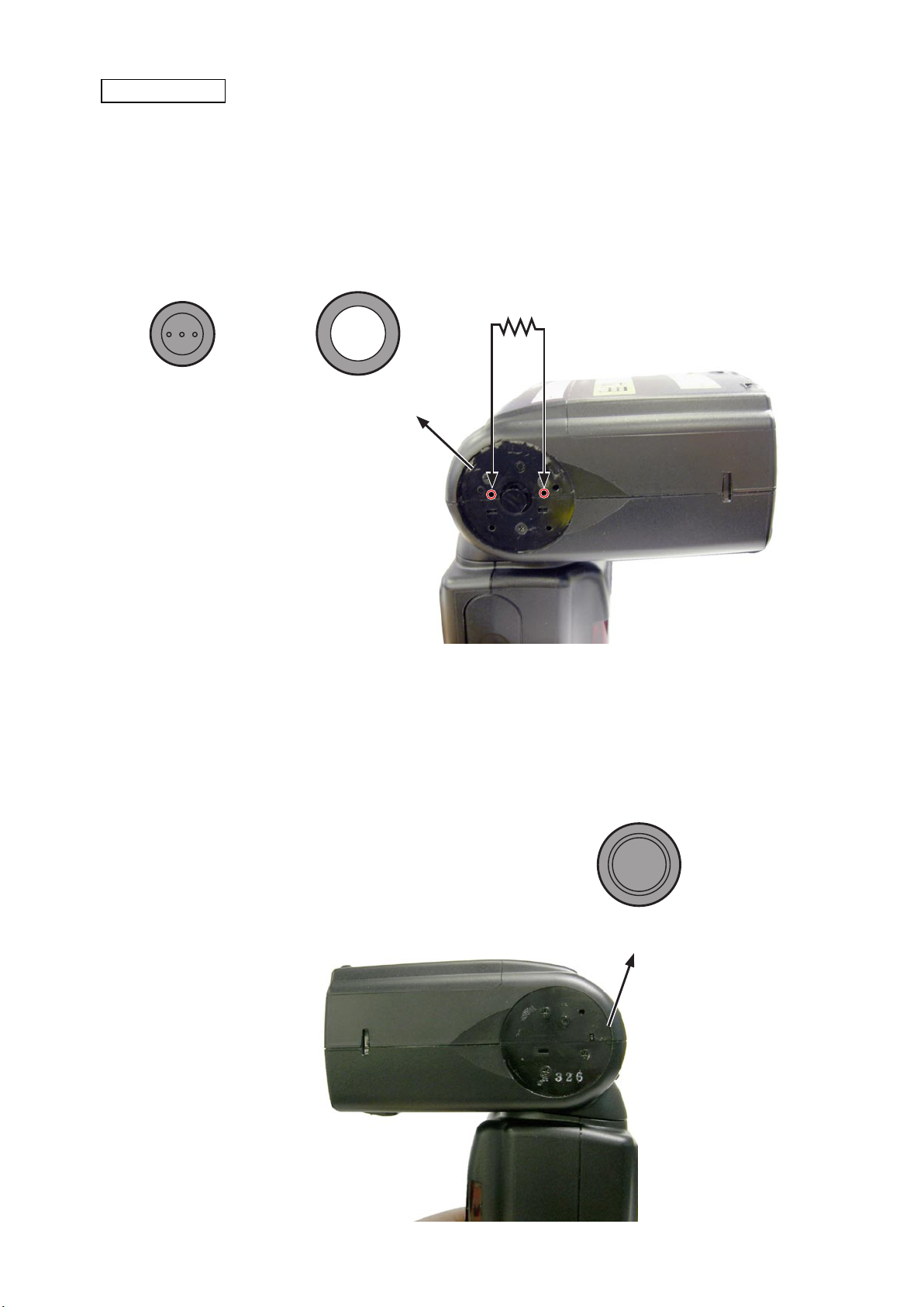
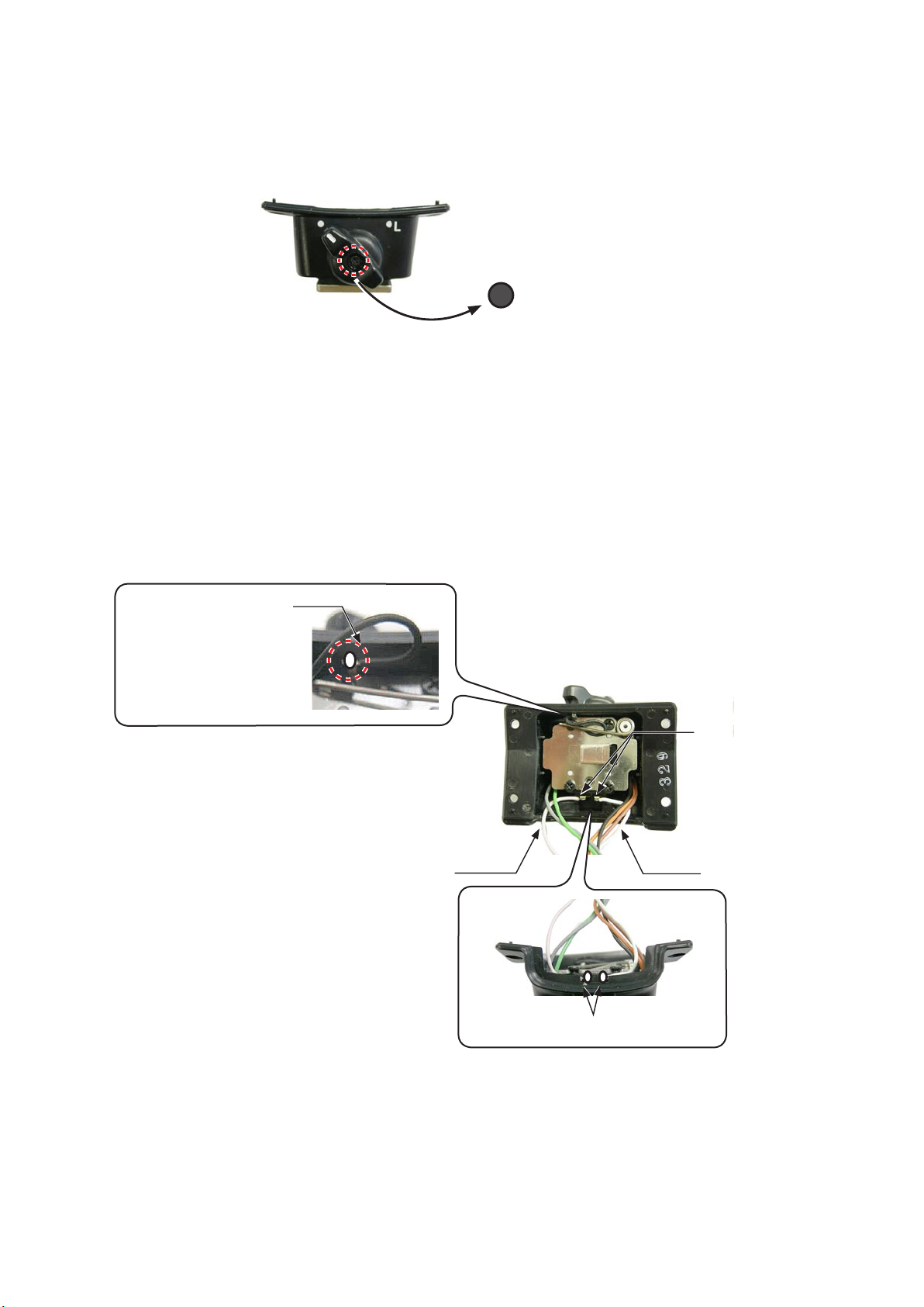
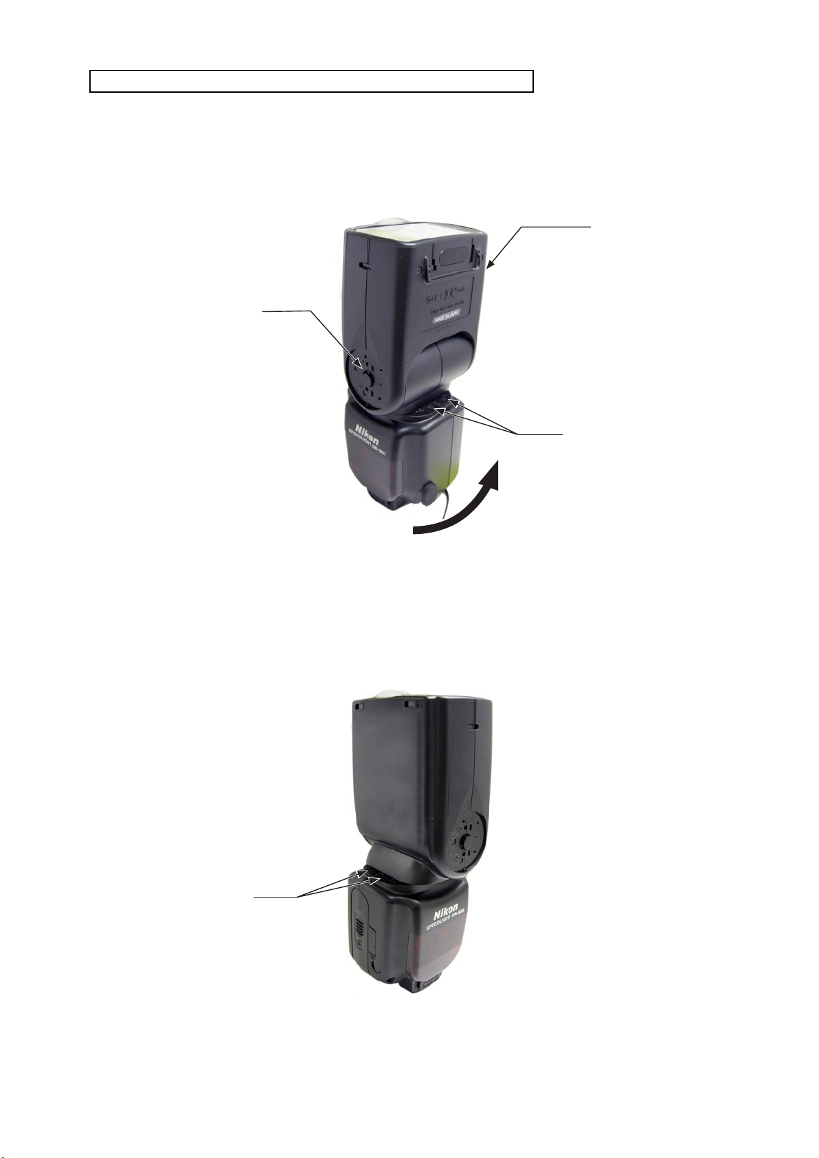
SIDE RUBBER
Remove the SIDE RUBBER [#008] and SIDE MOLD (A) [#009]
・
DISCHARGE OF MAIN CONDENSER: Set the bounce angle to "90°", and discharge through the two holes as
・
shown in "Fig.1".
200 Ω - 2k Ω
SIDE MOLD (A) [#009]SIDE RUBBER [#008]
・Remove the SIDE MOLD (B) [#010]
Fig.1
SIDE MOLD (B) [#010]
- D ・ SB-900 -
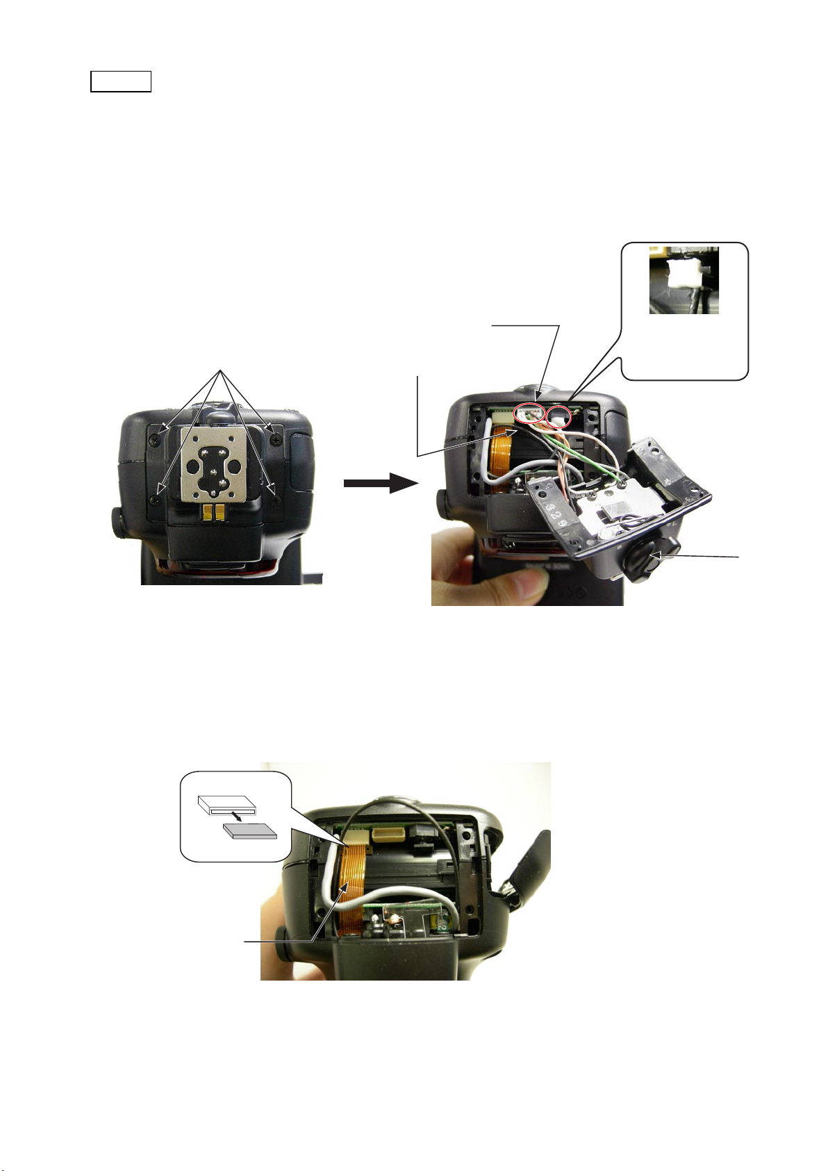
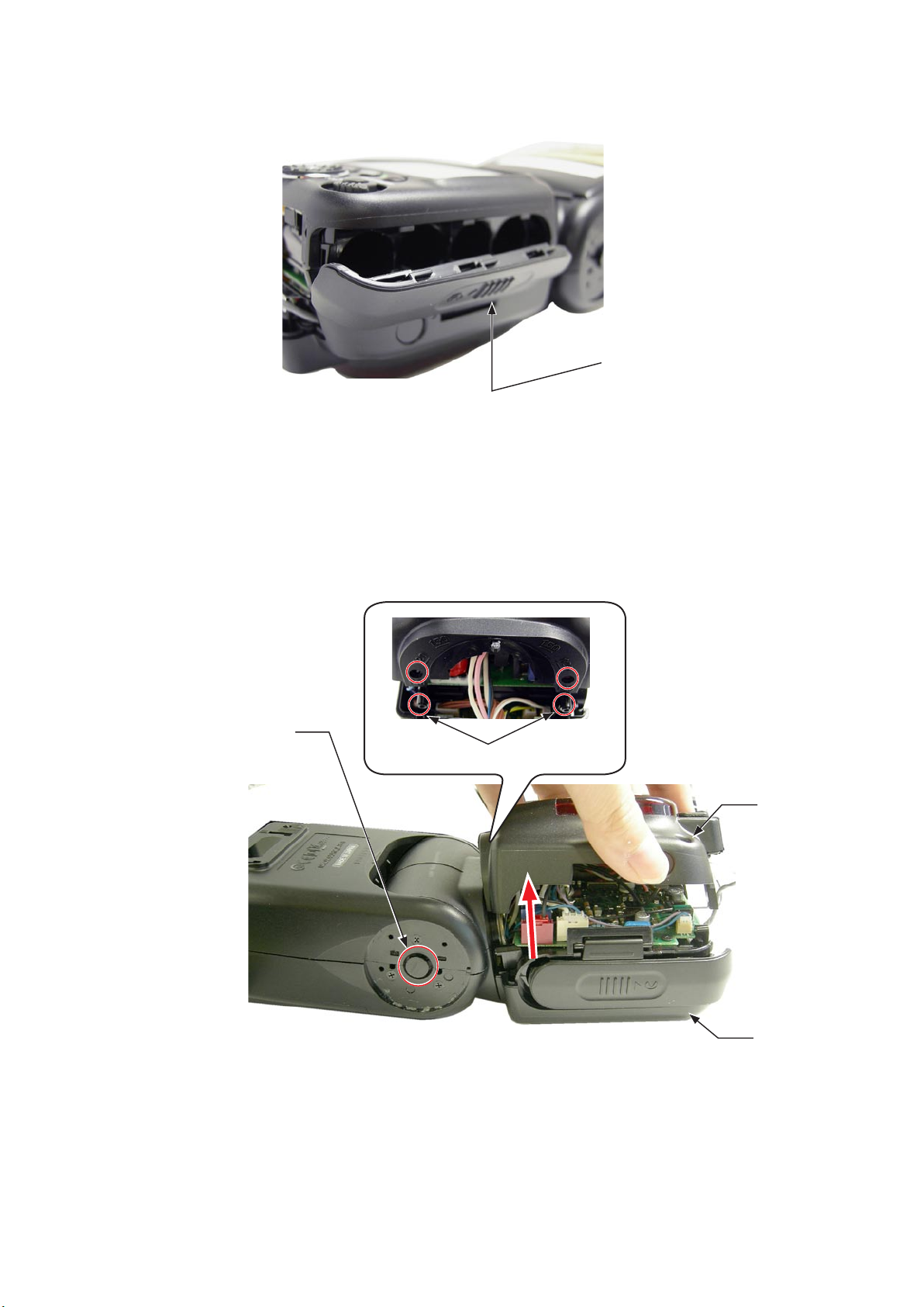
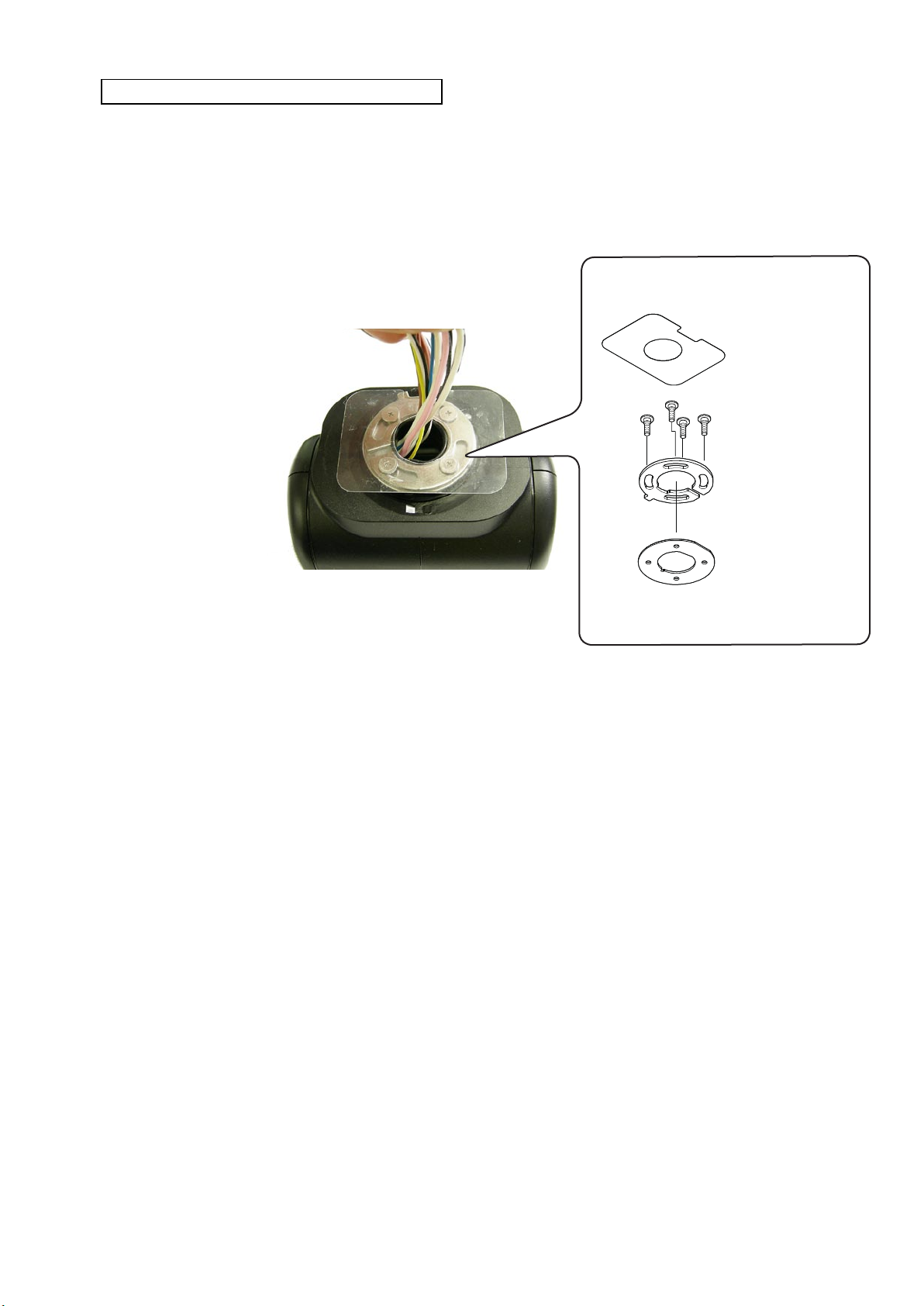
SHOE
INC
Take out the four screws [#005].
・
Remove the lead wire set (CN-9A).
・
Remove the ber cable [#068] from the retainer plate [#202].
・
The shoe comes off.
・
FSA03801-R.3756.A
SCREW [#005] × 4
・Disconnect the FPC (A) from the connector.
CONNECTOR
FIBER CABLE [#068]
RETAINER PLATE
[#202]
SHOE
FPC (A)
- D ・ SB-900 -
・Remove the Shoe lock lever cover [#163].
INC
Unsolder the GND side spring of the SHOE.
・
Unsolder AF-ILL contact at two places.
・
FSA03801-R.3756.A
SHOE LOCK LEVER COVER [#163]
Contact of GND side spring
of SHOE
Pinc lead wire
Black lead wire
AF-ILL CONTACT [#178]
×2
White lead wire
Unsolder×2
- D ・ SB-900 -
Remove the AF-ILL contact [#178] from the two places of the shoe case.
INC
・
AF-ILL CONTACT [#178] × 2
While picking up the front side with tweezers, etc, lift upwards and
remove [#178].
FSA03801-R.3756.A
Set the shoe lock lever [#162] to the UNLOCK position.
・
Remove the shoe lock spring [#170] from the cutout.
・
Shoe lock lever: UNLOCK positionShoe lock lever: LOCK position
The shoe lock spring is hooked to the cutout.
Pick up the shoe lock spring with
tweezers, and lift up to move.
Note that because the spring is hooked, the movement is a little unsmooth.
- D ・ SB-900 -
・Take out the four screws [#181].
INC
FSA03801-R.3756.A
SCREW [#181] × 2
・Remove the shoe plate [#164] from the shoe case [#161]
SHOE PLATE
SCREW [#181] × 2
[#164]
・Remove the shoe lock retainer [#167].
SHOE CASE
[#161]
SHOE LOCK RETAINER [#167]
SHOE LOCK BEARING [#166]
- D ・ SB-900 -
・Remove the shoe lock spring [#170].
INC
FSA03801-R.3756.A
SHOE LOCK SPRING [#170]
・Remove the shoe lock slide [#168].
SHOE LOCK SLIDE [#168]
・Remove the shoe lock plate [#169].
SHOE LOCK PLATE
[#169]
- D ・ SB-900 -
FSA03801-R.3756.A
INC
・Take out the screw [#180].
SHOE CASE [#161]
SHOE LOCK LEVER [#162]
SCREW [#180]
・Remove the shoe click block [#175] and shoe click spring [#174] from the shoe lock lever [#162].
Use caution to avoid popping out of the shoe click spring and shoe click block, because they are small.
SHOE CLICK BLOCK [#175]
SHOE CLICK SPRING
[#174]
SHOE LOCK LEVER
[#162]
・Remove the shoe lock pin [#171] from the shoe case [#161].
SHOE LOCK PIN [#171]
The shoe lock pin is inserted in the
hole.
- D ・ SB-900 -
Pull out the shoe lock pin mold [#172] from the hole of the shoe lock bearing [#166].
INC
・
SHOE LOCK PIN MOLD
Hole
[#172]
FSA03801-R.3756.A
SHOE LOCK BEARING
[#166]
・Remove the shoe lock pin spring [#173].
SHOE LOCK AXLE [#165]
SHOE LOCK PIN SPRING [#173]
- D9 ・ SB-900 -
Remove the shoe lock pin [#171] from the shoe lock pin mold [#172].
INC
・
Hole viewed from above
Move the shoe lock
pin from small hole
FSA03801-R.3756.A
SHOE LOCK PIN MOLD [#172]
to big hole and
remove it.
Remove the shoe lock axle [#165] from the shoe lock bearing [#166] in numeric order from ① to②.
・
SHOE LOCK BEARING
[#166]
SHOE LOCK AXLE [#165]
・Remove the shoe GND spring [#177].
Concave section
SHOE LOCK PIN [#171]
③
①
②
The small leg of the
spring is caught on the
groove.
Small leg
Pull the long leg of the shoe
GND side spring from the
hole of the shoe case.
Long leg
- D0 ・ SB-900 -
・Take out the screw [#025].
INC
・Remove the shoe base unit [#192] from the shoe case [#161].
FSA03801-R.3756.A
SCREW [#025]
・Remove the four shoe contact pins [#176] from the shoe base unit [#192].
SHOE CONTACT PIN[ #176] × 2
SHOE CONTACT
PIN [#176] × 2
SHOE BASE
UNIT [#192]
SHOE CASE [#161]
- D ・ SB-900 -
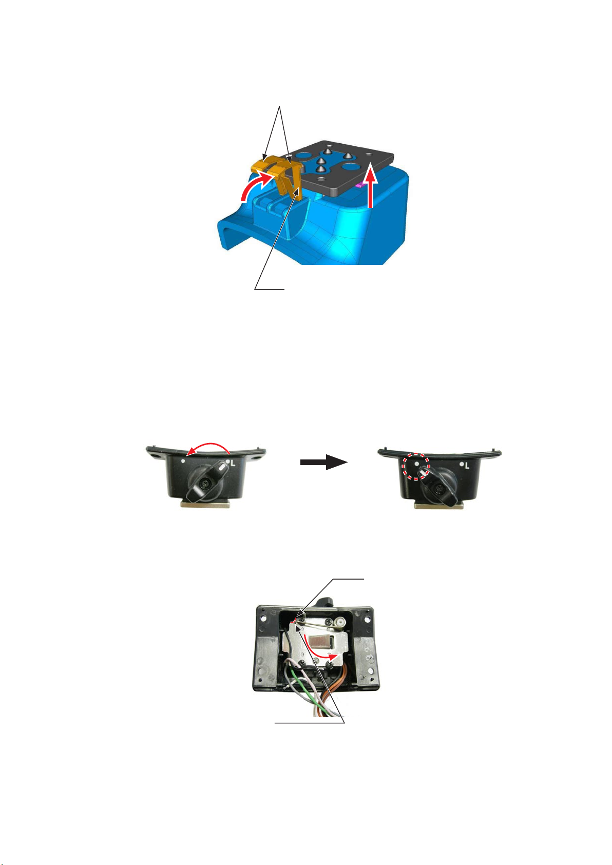
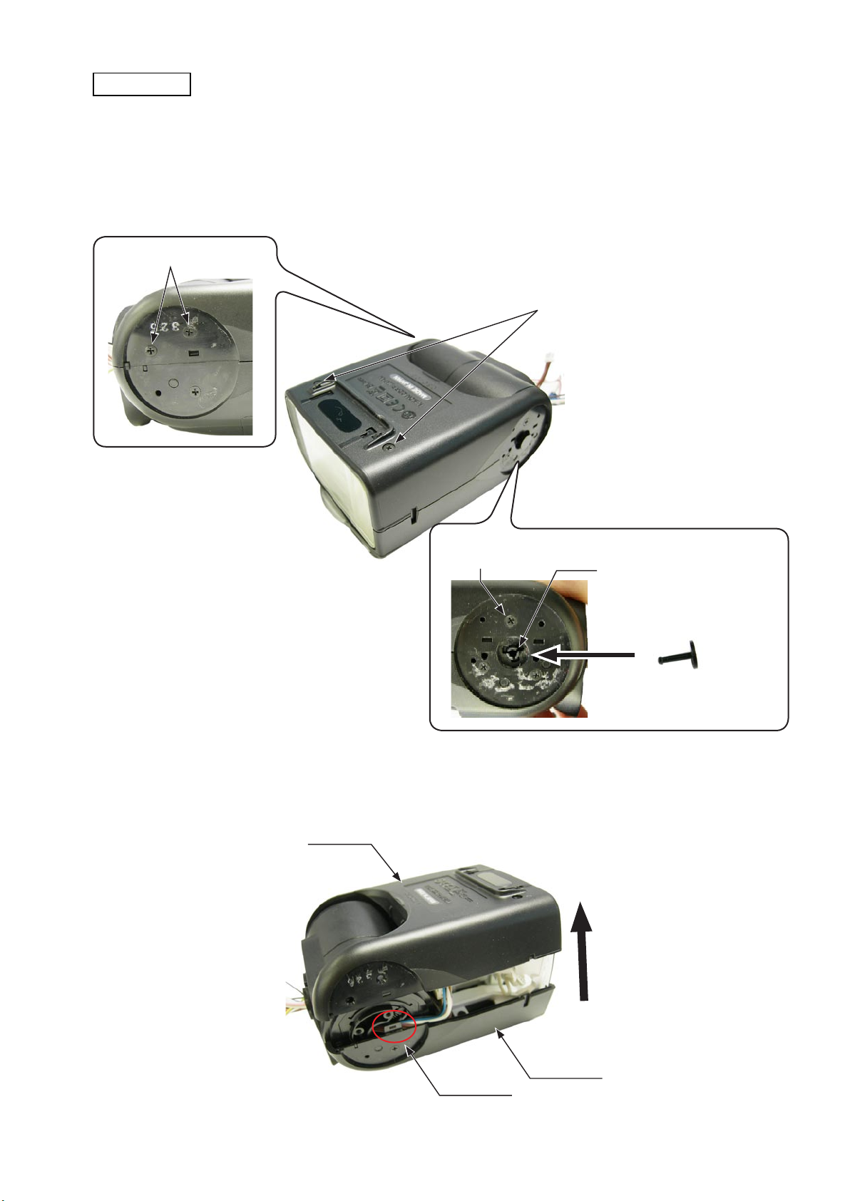
HEAD UNIT / BATTERY CHAMBER MOLD / COVER (E) / COVER (F)
INC
While pressing the bounce lock pin [#017], give the head unit half-turn.
・
Take out the screw [#005].
・
BOUNCE LOCK PIN [#017]
FSA03801-R.3756.A
HEAD UNIT
SCREW [#005] × 2
Take out the two screws [#005] on the other side.
・
SCREW [#005] × 2
- D ・ SB-900 -
Open the battery lid [#159].
INC
・
FSA03801-R.3756.A
BATTERY LID [#159]
While pressing the bounce lock pin [#017], separate the
・
BOUNCE LOCK PIN [#017]
cover(E)
HOOK
[#086] from the
cover(F)
[#112].
COVER (E)
[#086]
COVER (F) [#112]
- D ・ SB-900 -
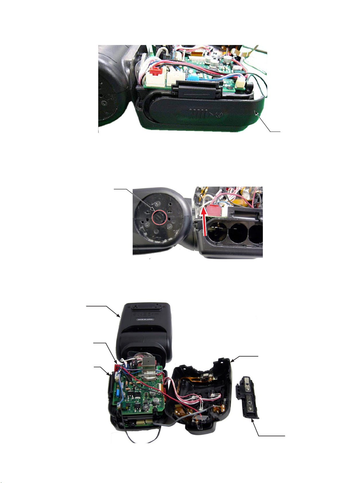
The battery lid [#159] comes off.
INC
・
While pressing the bounce lock pin [#017], remove the battery chamber from the head unit.
・
FSA03801-R.3756.A
BATTERY LID
[#159]
BOUNCE LOCK PIN [#017]
SB is divided into the
・
Remove the LEAD WIRE SET (CN-6) [Black/Red] [#104] from the red connector.
・
HEAD UNIT
LEAD WIRE SET
(CN-6) [Black/Red]
[#104]
cover(E)
[#086],
cover(F)
[#112]/battery chamber, battery lid [#159], and head unit.
COVER (F)[#112]/
BATTERY CHAMBER
MOLD
COVER(E)[#086]
BATTERY LID
[#159]
- D ・ SB-900 -

FSA03801-R.3756.A
INC
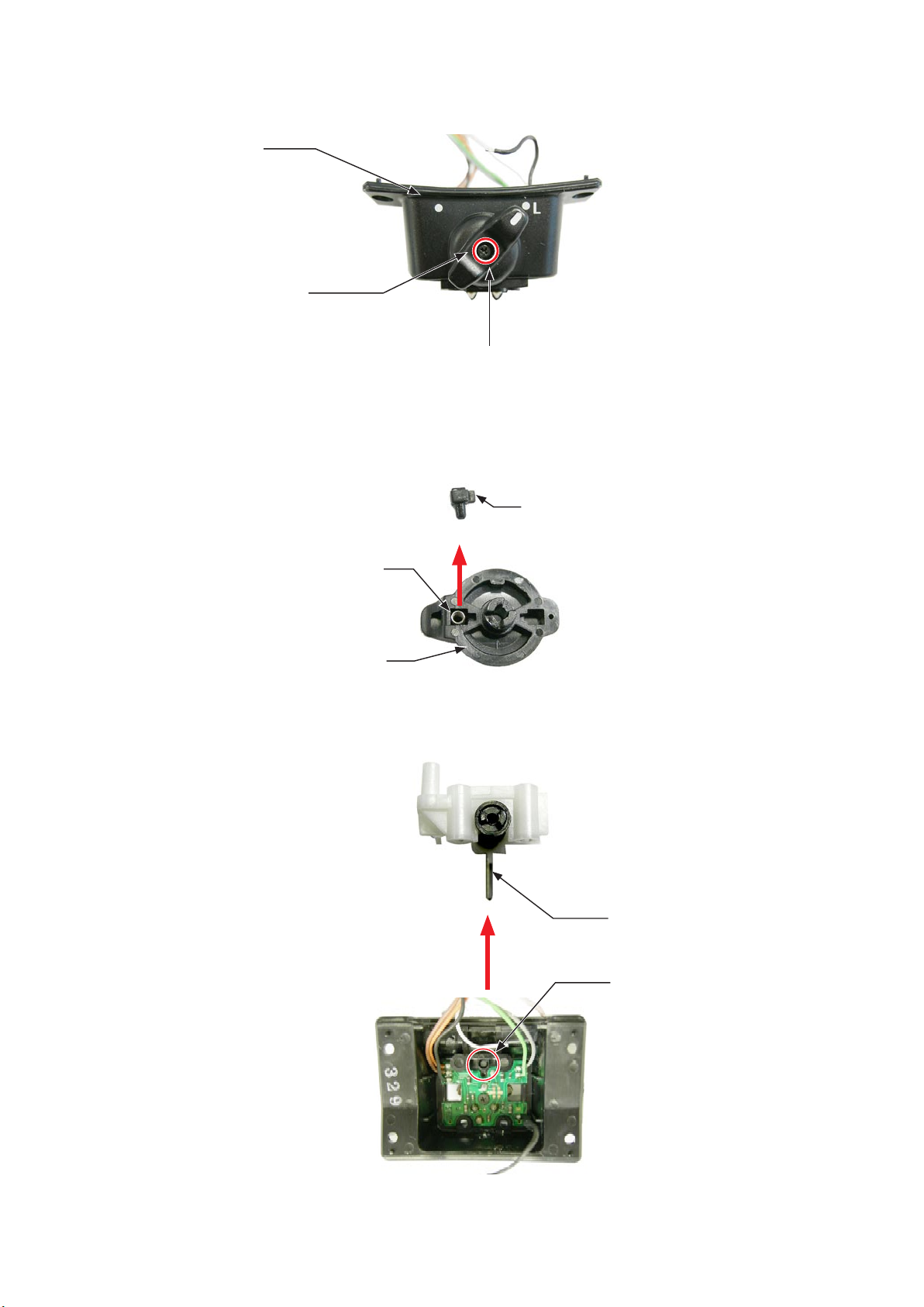
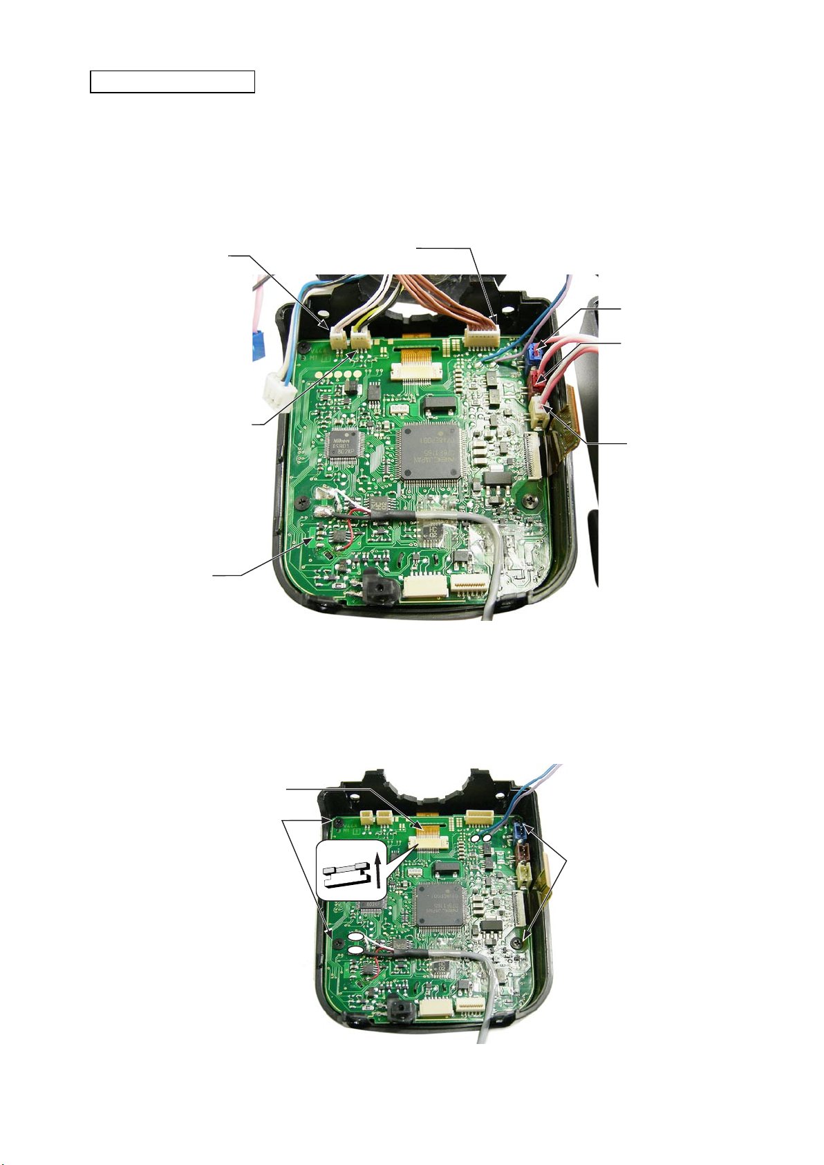
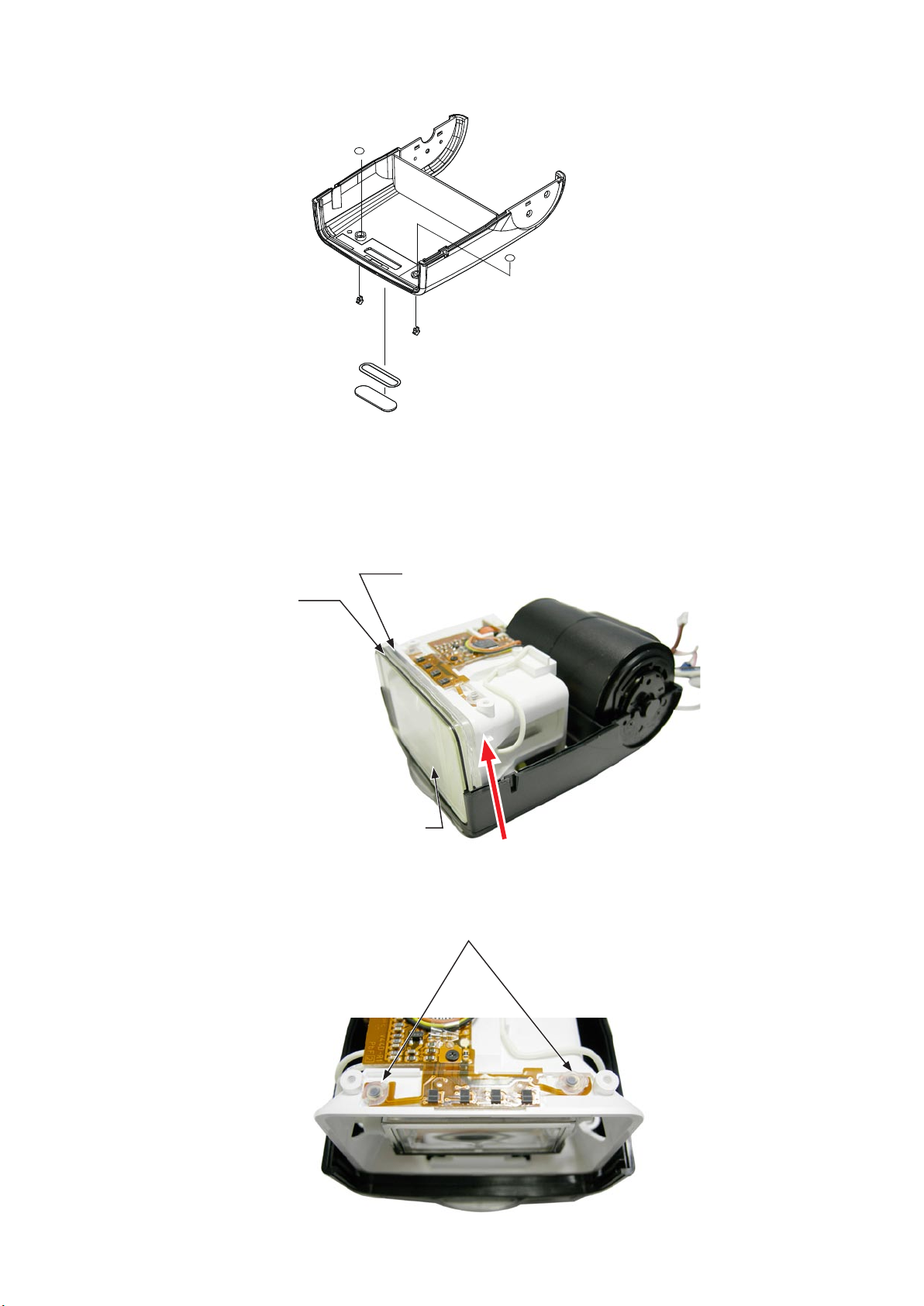
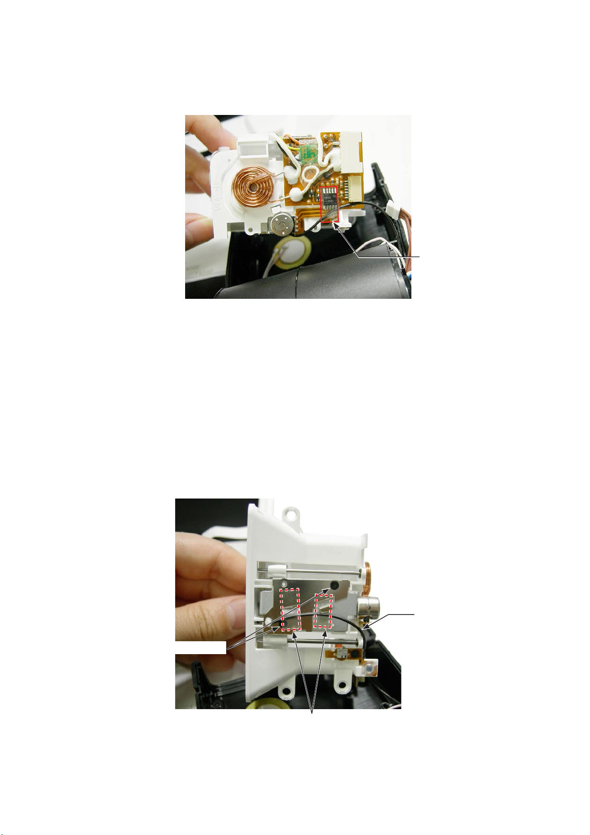
Remove the lead wire set (CN-17) [Red/White][#194] together with the slave plate from the cover (E) [#086].
・
SLAVE PLATE
Lift upwards.
LEAD WIRE SET (CN-17)
[Red/White] [#194]
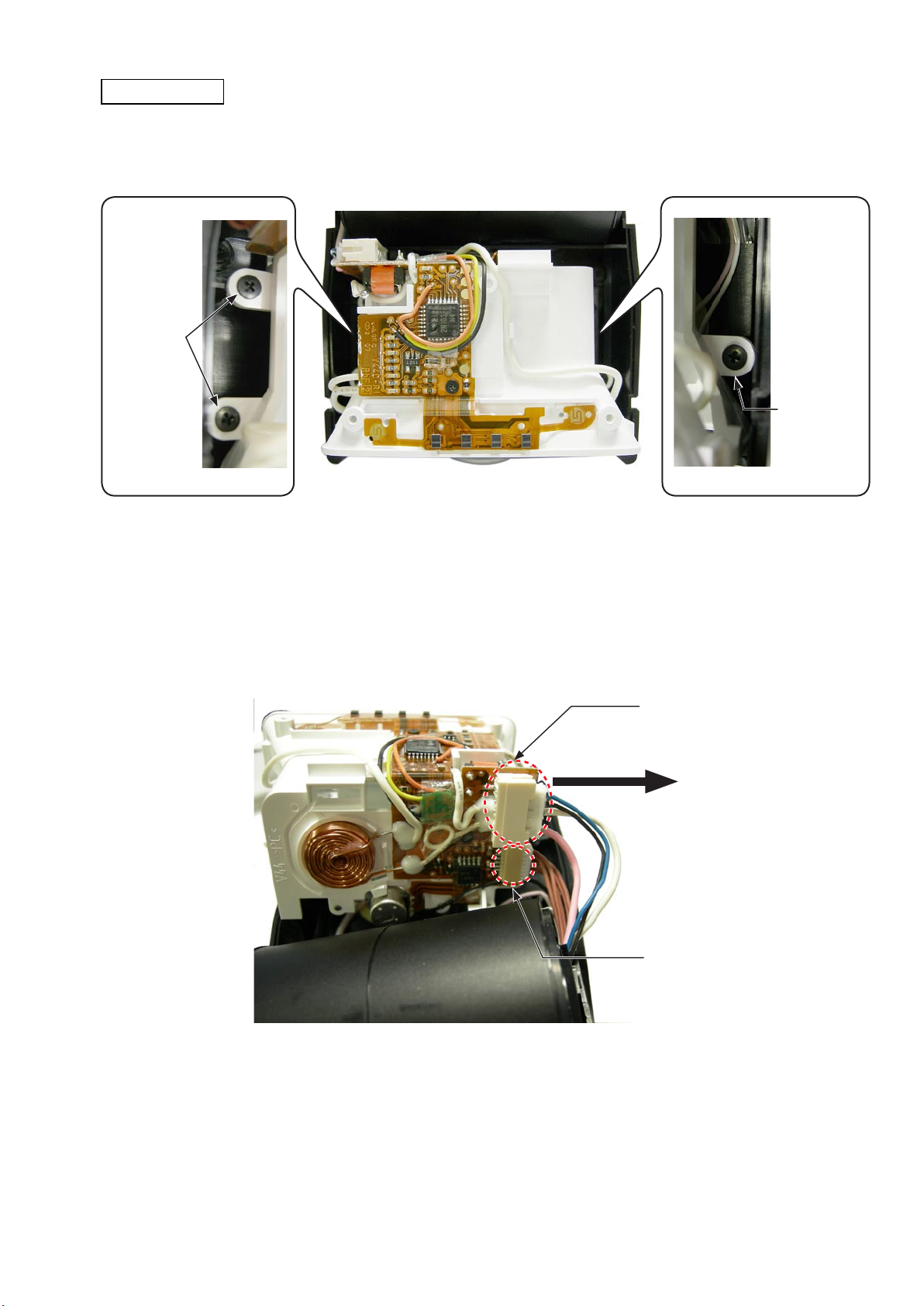
Disconnect the lead wire set (CN-3) [Blue/Black/White] [#070] from the white connector (small).
・
Disconnect the lead wire set (CN-7) [Pink/White][#082] from the blue connector.
・
Disconnect the lead wire set (CN-10) [Blue/Black/White] [#185] from the white connector (large).
・
Disconnect the FPC lead [#004] from the connector.
・
Leave the ber cable exposed outside of the case.
・
LEAD WIRE SET (CN-7)
[Pink/White] [#082]
LEAD WIRE SET (CN-3)
[Blue/Black/White][#070]
LEAD WIRE SET (CN-10)
[Blue/Purple] [#185]
FIBER CABLE [#068]
FPC LEAD [#004]
- D ・ SB-900 -
FSA03801-R.3756.A
INC
Release the four protrusions of the battery chamber mold (A)[#148] from each hole of the cover (E)[#086].
・
Protrusion×2
Hole × 2
Protrusion×2
HEAD UNIT
BATTERY CHAMBER
MOLD
LEAD WIRE SET
Hole × 2
Push the lead wire set (CN-17)[Red/White] to the
side of the connector.
(CN-17) [Red/White]
COVER (F) [#112]
COVER (E) [#086]
- D ・ SB-900 -
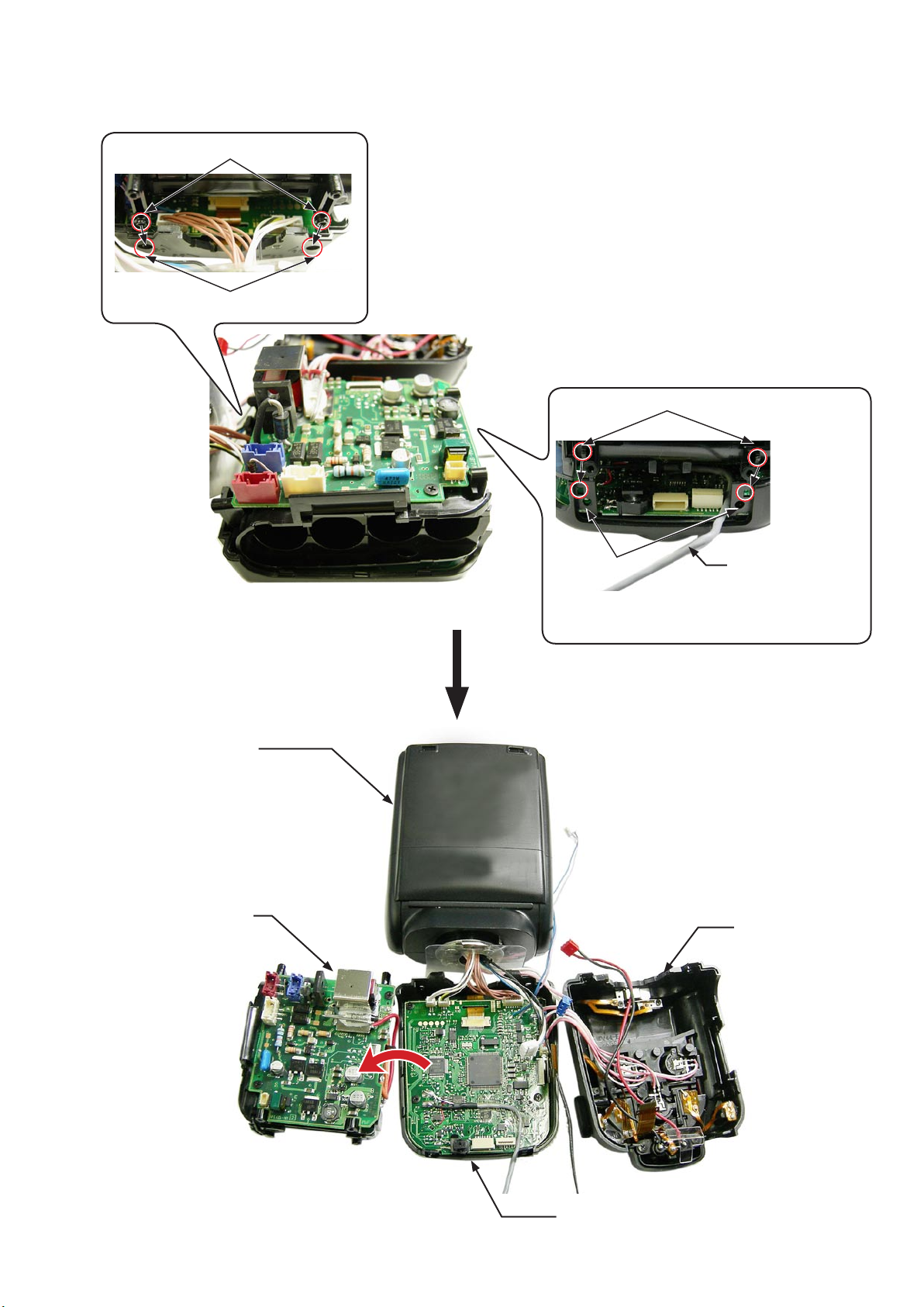
PRINTED CIRCUIT (A)
INC
FSA03801-R.3756.A
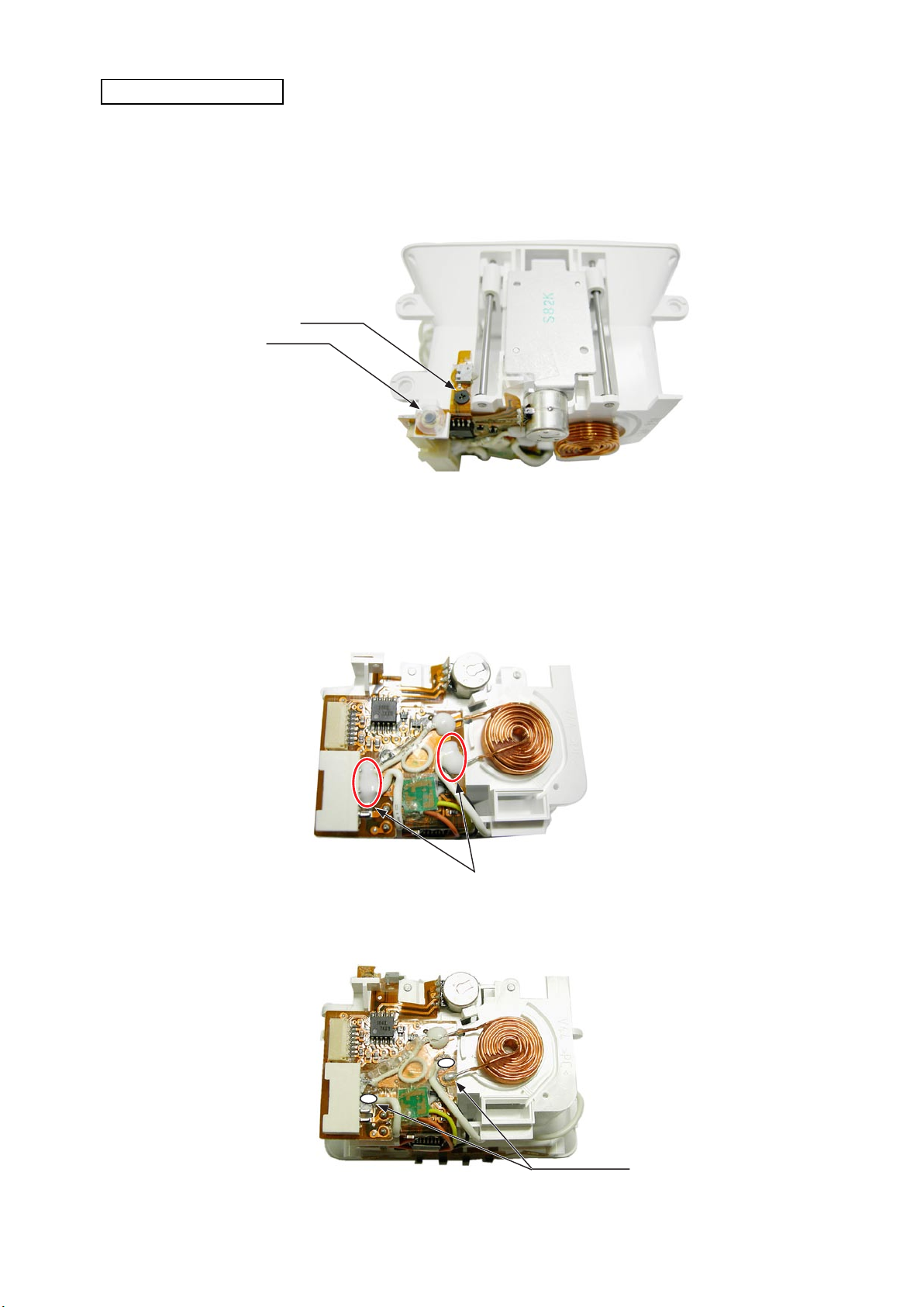
Remove the lead wire set (CN-16) (Pink/White)
・
wire set (CN-2)(Brown)[#069] from the printed circuit (A) [#147].
Remove the AF module unit (blue wire)[#195], AF module unit (red wire)[#196], and AF module unit (white
・
wire)[#197] from the cover(E)[#086].
LEAD WIRE SET (CN-2)
LEAD WIRE SET(CN-16)
(Pink/White)[#071]
LEAD WIRE SET
(CN-5A)(Yellow/White/
Black)[#203]
(Brown)[#069]
[#071], lead wire set (CN-5A)(Yellow/White/Black)[#203], and lead
AF MODULE UNIT
(BLUE) [#195]
AF MODULE UNIT
(RED)[#196]
AF MODULE UNIT
(WHITE) [#197]
PRINTED CIRCUIT (A)
[#147]
Take out the four screws [#005].
・
Disconnect the FPC of LCD [#198] from the connector.
・
FPC of LCD[#198]
SCREW [#005] × 2
SCREW [#005] × 2
- D ・ SB-900 -
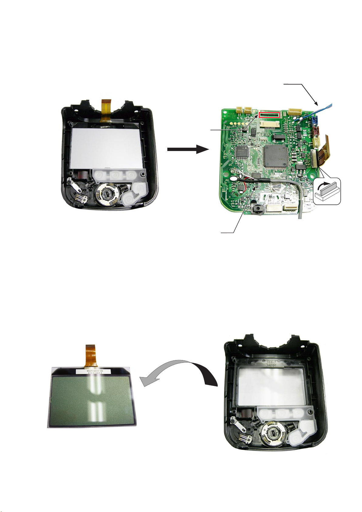
Remove the FPC of the LCD [#198] by passing through the hole of the printed circuit (A)[#147].
INC
・
Unsolder the lead wire set (CN-17) [Red/White] [#194] at three places.
・
Unsolder the lead wire set (CN-10) [Blue/Purple][#185].
・
LEAD WIRE SET(CN-10)
[Blue/Purple][#185]
Hole
FSA03801-R.3756.A
COVER (F) [#112]
・Remove the LCD[#198].
LEAD WIRE SET (CN-17)
[Red/White] [#194]
PRINTED CIRCUIT (A) [#147]
LCD [#198]
COVER (F) [#112]
- D ・ SB-900 -
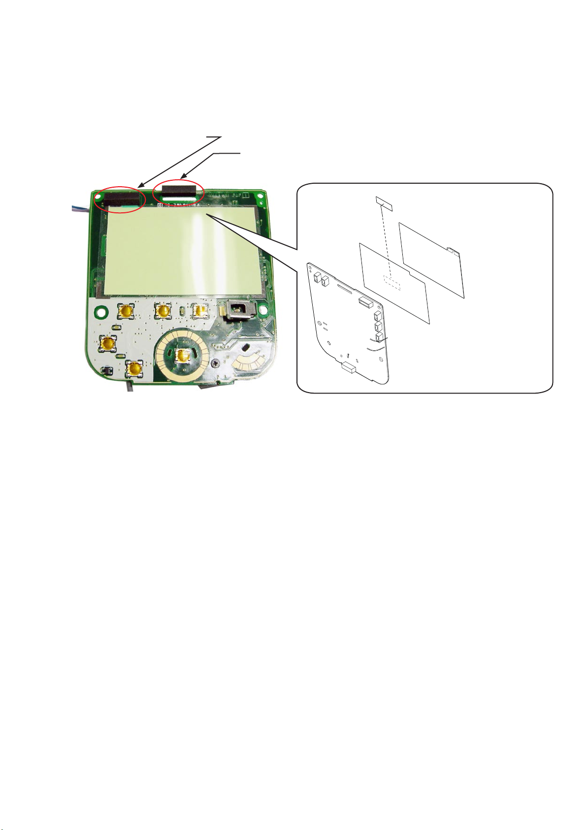
・Remove the LCD cushion (A) [#116].
INC
・Remove the LCD cuchion (B) [#117].
・Remove the electrical luminance plate [#118].
・Remove the insulator sheet [#119].
LCD CUSHION (A) [#116]
LCD CUSHION (B) [#117]
FSA03801-R.3756.A
DOUBLE-STICK TAPE B
[#120]
ELECTRICAL
LUMINACE
PLATE [#118]
INSULATOR SHEET
PRINTED CIRCUIT (A) [#147] back side
[#119]
PRINTED CIRCUIT (A) [#147]
- D9 ・ SB-900 -
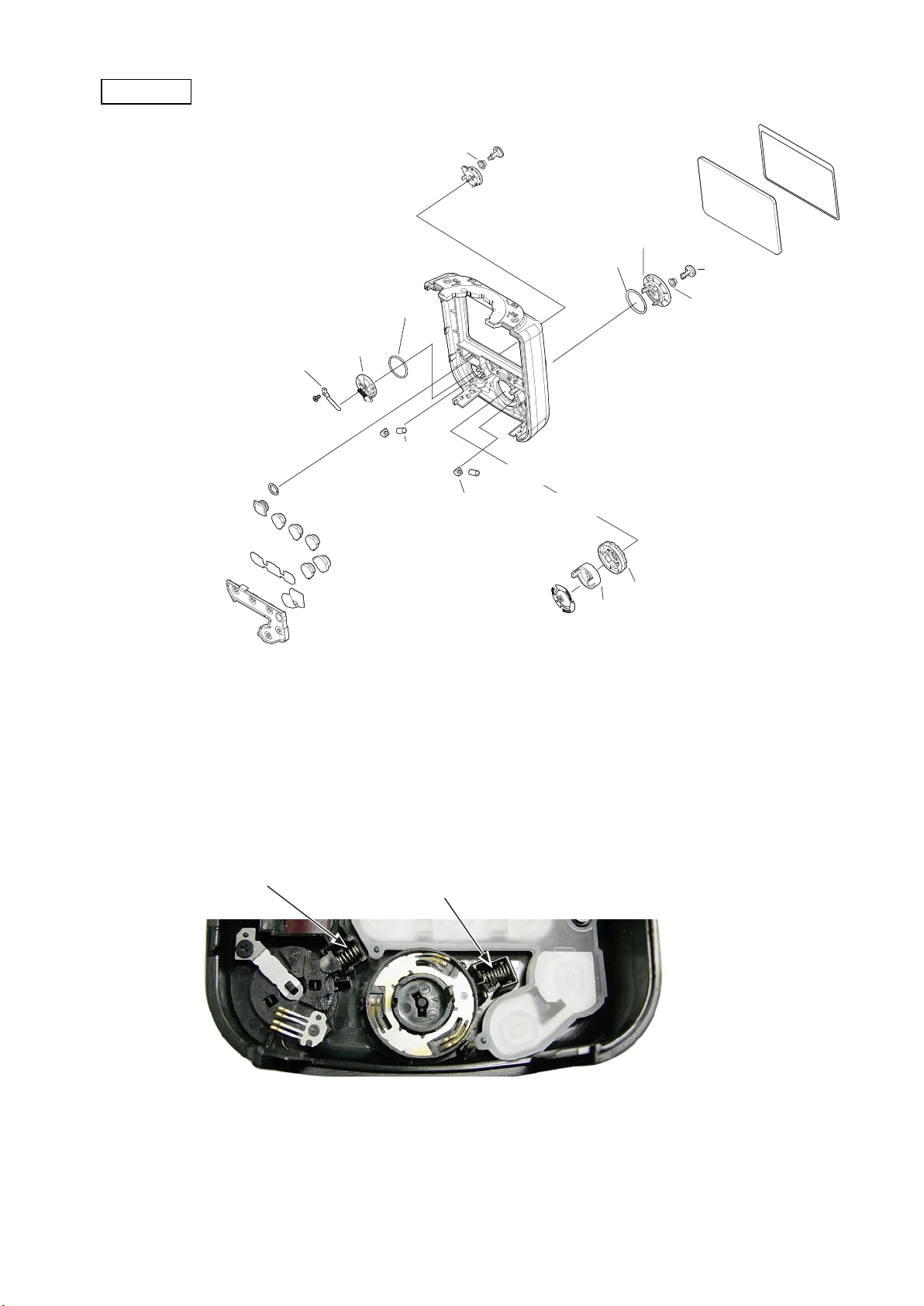
COVER (F)
INC
LOCK RELEASE BUTTON [#142]
OK BUTTON RUBBER [#136]
FSA03801-R.3756.A
DOUBLE STICK TAPE (C) [#114]
LCD WI N DO W
[#113]
POWER SOURCE SW KNOB [#137]
DIAL (A) [#128]
O RING [#129]
OK BUTTON [#135]
KNOB HOLDER [#139]
LOCK RELEASE SPRING [#144]
SCREW [#025]
CLICK POST [#133]
O RING [#125]
TEST BUTTON [#124]
SW NAME PLATE (A)
[#121]
RUBBER [#123]
O RING [#138]
CLICK SP(A) [#134]
CLICK POST [#133]
SW KNOB (B) [#127]
SW KNOB (A) [#126]
SW NAME PLATE (B) [#122]
SW BRUSH (A) [#132]
OK BUTTON R U BBER
[#136]
COVER (F) [#112]
CLICK SP (B) [#141]
DIAL (B) [#130]
BUTTON HOLDER [#131]
Caution: When the power button or OK button is removed, the click SP or click post may pop out.
CLICK SP (A) [#134]
CLICK SP (B) [#141]
- D0 ・ SB-900 -
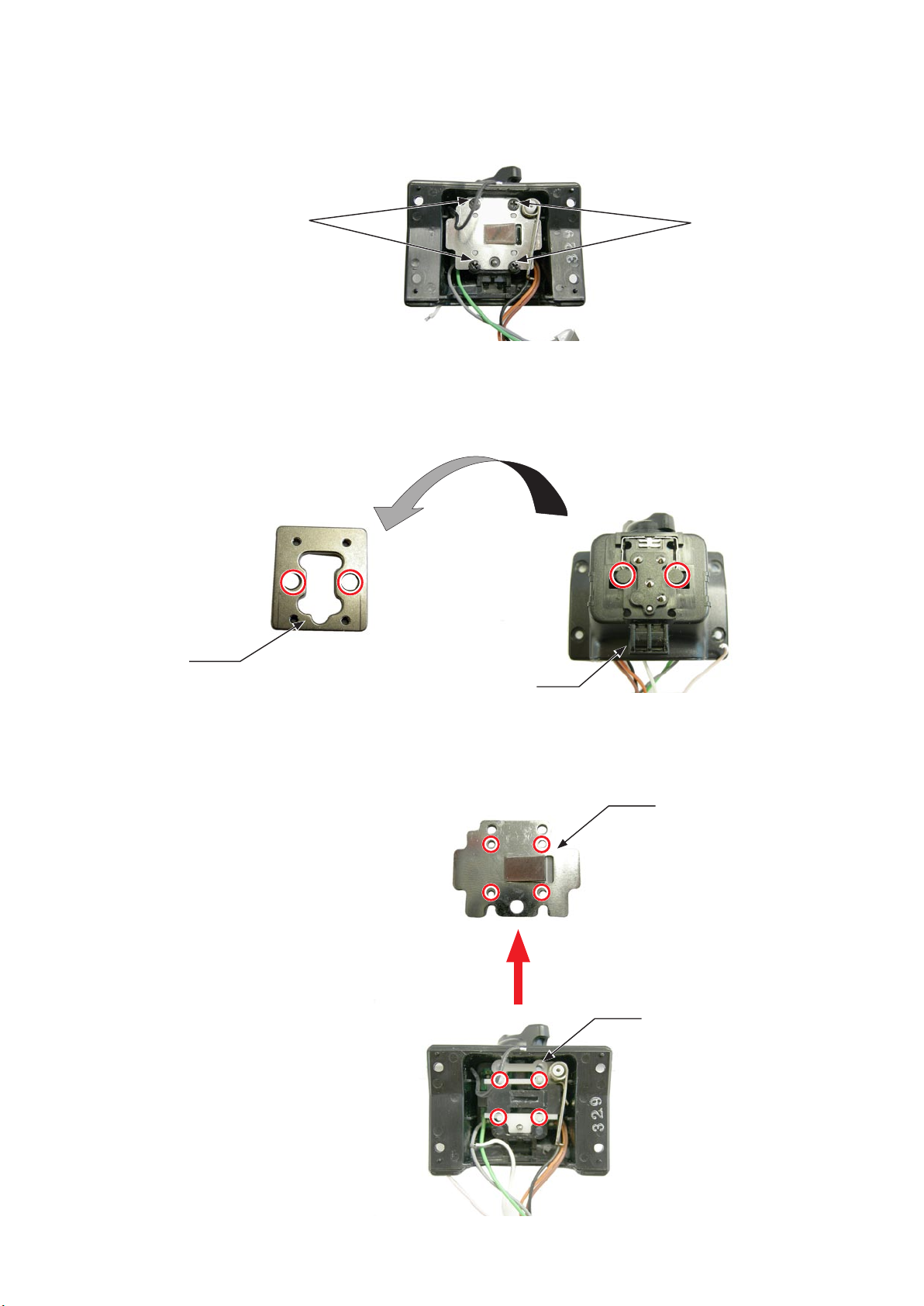
TURN PLATE / HEAD NECK HOLDER PLATE
INC
FSA03801-R.3756.A
・Remove the tetron sheet
・Take out the four screws [#024].
・Remove the head neck holder plate [#023] and turn plate [#022].
(C) [#002].
TETORON SHEET (C) [#002]
SCREW [#024] × 4
TURN PLATE [#022]
HEAD NECK HOLDER PLATE [#023]
- D ・ SB-900 -
COVER (B)
INC
Take out the right-side screw.
・
Pull out the bounce lock pin.
・
Take out the left-side two screws.
・
Take out the top two screws.
・
SCREW [#026] × 2
FSA03801-R.3756.A
SCREW [#005] × 2
Unhook the cover (B)[#027] from the cover (A)[#031].
・
The cover (B)[#027] will come off.
・
COVER (B) [#027]
SCREW [#026]
U/D LOCK LEVER [#019]
BOUNCE LOCK PIN [#017]
COVER (B) [#031]
HOOK
- D ・ SB-900 -
SW SHEET [#199]
INC
SWITCH POST [#030]
・Remove the acrylic panel [#015].
FSA03801-R.3756.A
COVER (B) [#027]
SW SHEET [#199]
SWITCH POST [#030]
DOUBLE STICK TAPE (B) [#028]
DETECTION WINDOW [#029]
・Remove the panel packing [#016] from the acrylic panel [#015].
・Remove the fresnel lens [#014].
FRESNEL LENS [#014]
PANEL PACKING [#016]
ACRYLIC PANEL [#015]
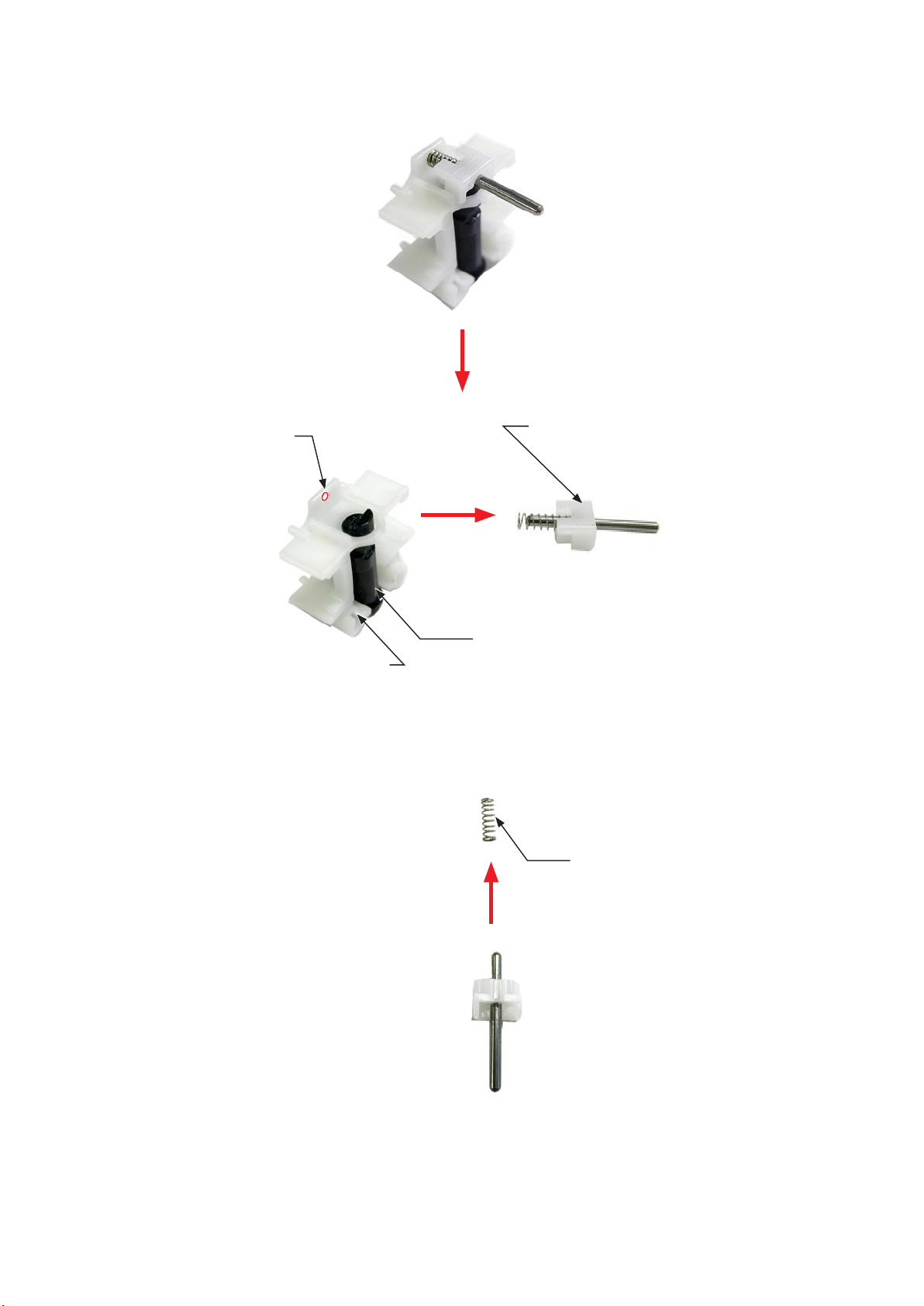
Remove the two detection SWs [#054], (because they are so light as to be popped out easily, and they may be missing
・
during disassembly.)
DETECTION SW [#054] × 2
- D ・ SB-900 -
FIBER CABLE
INC
・Take out the three screws [#005].
SCREW
[#005] × 2
FSA03801-R.3756.A
SCREW
[#005]
Lift the hood slightly upward, and remove the lead wire set [(CN-3)(Pink/White/Black/Blue)][#070].
・
Remove the lead wire set (CN-2) (Brown)[#069].
・
LEAD WIRE SET(CN-3)
(Pink/White/Black/Blue)
[#070]
Pull out.
LEAD WIRE SET (CN-2)
(Brown)[#069]
- D ・ SB-900 -
・Peel off the tape.
INC
FSA03801-R.3756.A
TAPE
Peel off the tape at two places.
・
Remove the ber wire [#068] from the hole.
・
Take out the two screws [#025].
・
The ber retainer plate [#001] will come off.
・
SCREW [#025]
FIBER CABLE [#068]
Tape xing position
- D ・ SB-900 -
PRINTED CIRCUIT (D)
INC
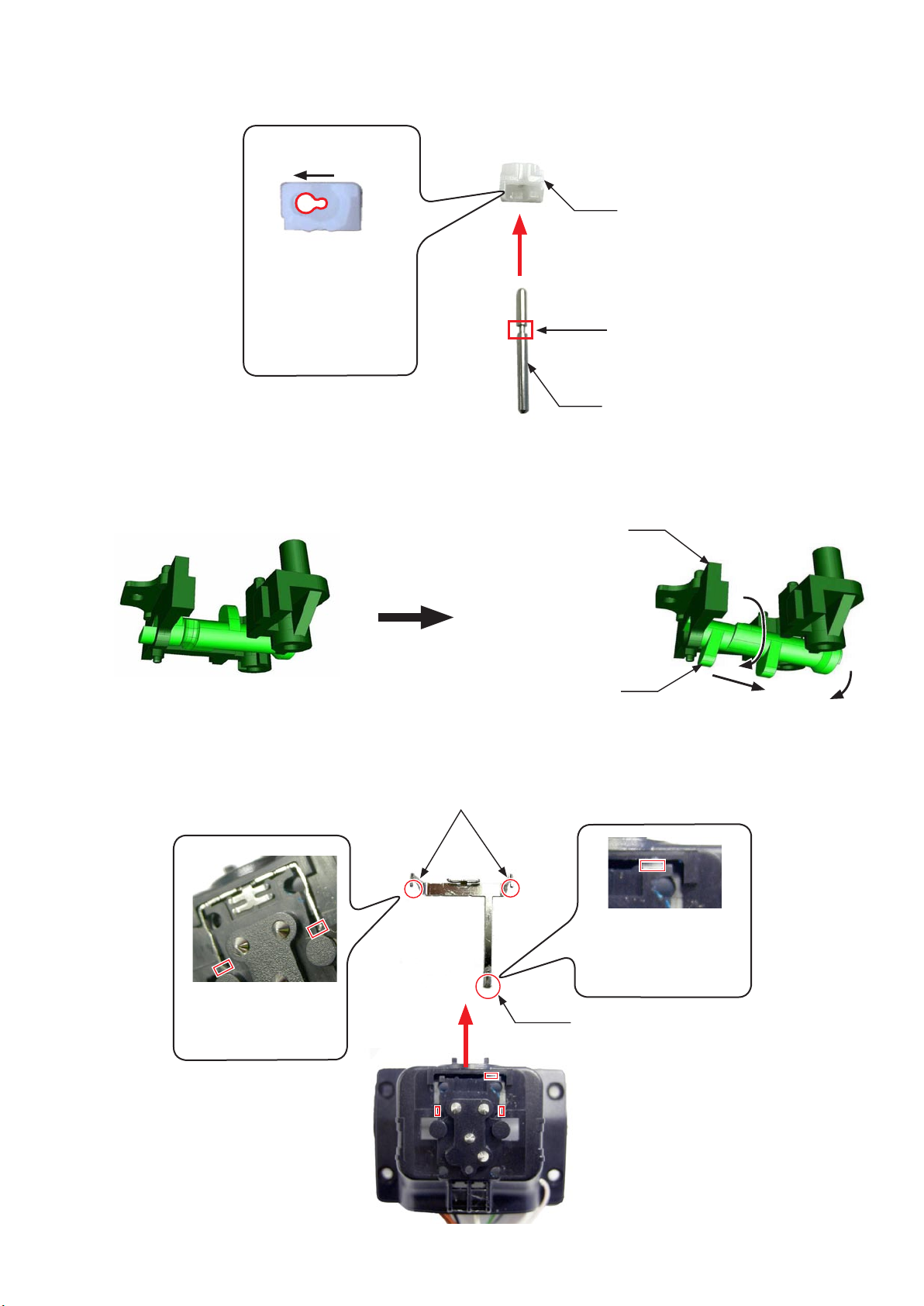
・Remove the detection SW [#054].
・Take out the screw [#025].
SCREW [#025]
DETECTION SW [#054]
FSA03801-R.3756.A
Remove the bonds at two places.
・
・Unsolder at two places.
Bond ×2
Unsolder here.
- D ・ SB-900 -
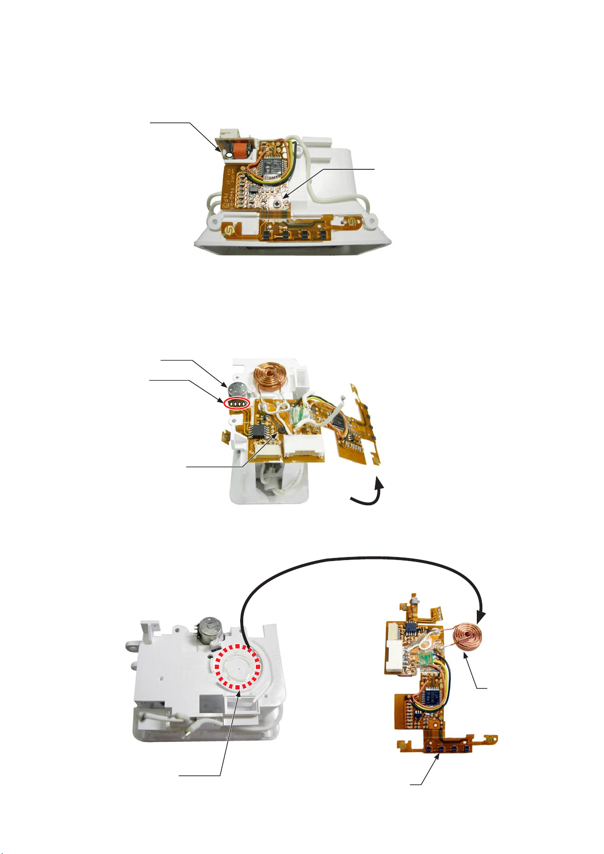
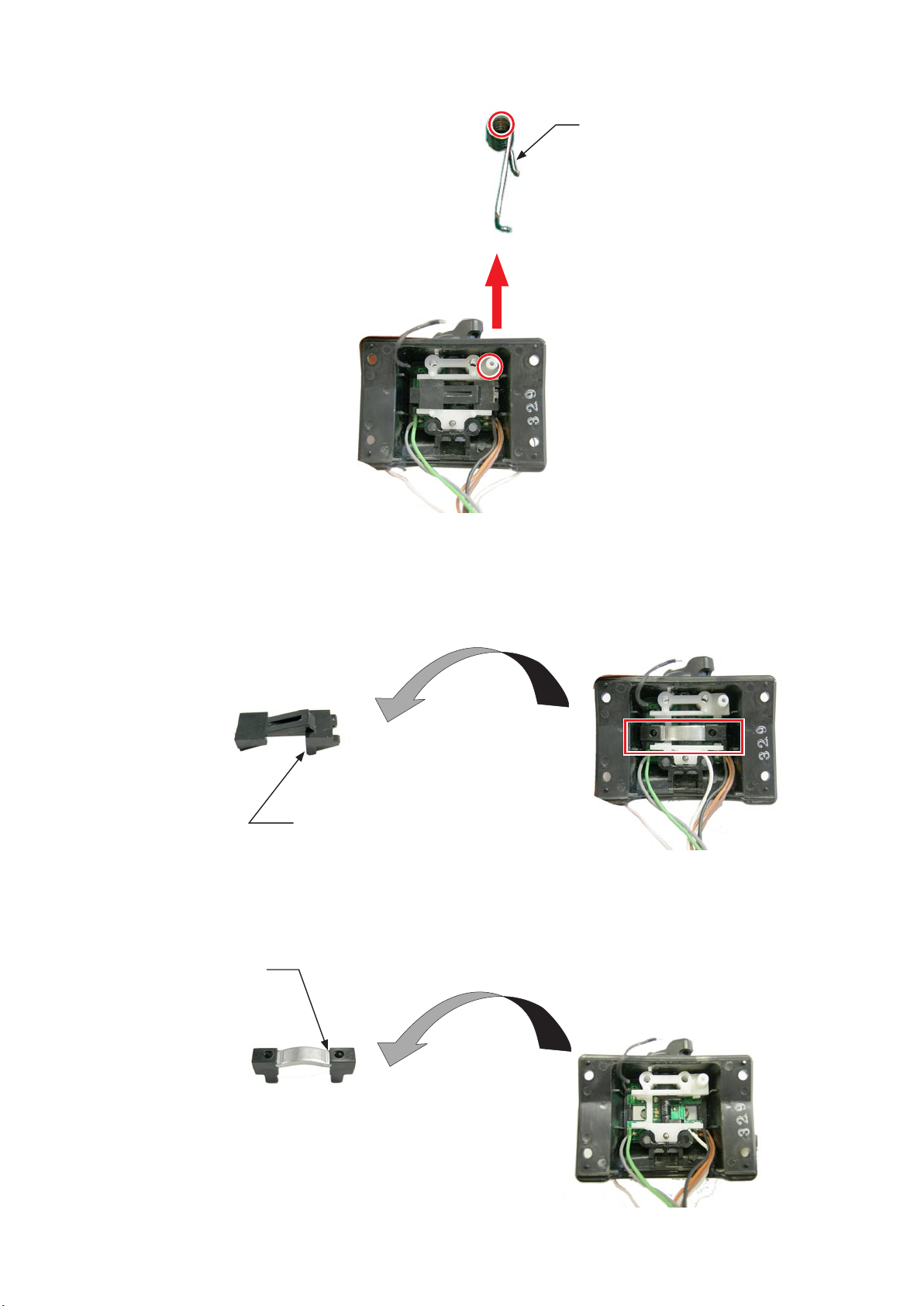
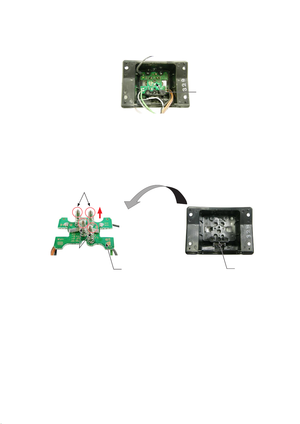
Take out the screw [#025].
INC
・
Remove the solder.
・
Unsolder here.
Raise the printed circuit (D) [#193].
・
Take out the screw [#025].
・
Unsolder the motor terminal at four places.
・
FSA03801-R.3756.A
SCREW [#025]
Motor terminal
Unsolder ×4
SCREW [#025]
・Remove the printed circuit (D) [#193].
INDUCTOR [#191]
The inductor is attached
with bond.
PRINTED CIRCUIT (D) [#193]
- D ・ SB-900 -
 Loading...