


SB-5000
User’s Manual
Nikon Manual Viewer 2
Install the Nikon Manual Viewer 2 app on your
smartphone or tablet to view Nikon digital
camera manuals, anytime, anywhere. Nikon
Manual Viewer 2 can be downloaded free of
charge from the App Store and Google Play.
Speedlight
En
Preparation
About the SB-5000 and This User’s
A
Manual
Thank you for purchasing the Nikon Speedlight SB-5000. To get the most
out of your Speedlight, please read this user’s manual thoroughly before
use.
Preparation
For your safety
Before using the Speedlight for the first time, read the safety instructions in
“For Your Safety” (0A-7 – A-10).
Included items
Check that all items listed below are included with the SB-5000. If any
items are missing, inform the store where the SB-5000 was purchased or
the seller immediately.
• Speedlight Stand AS-22 • Soft Case SS-5000
• Nikon Diffusion Dome SW-15H • Accessory pouch
• Fluorescent Filter SZ-4FL • Incandescent Filter SZ-4TN
• User’s manual (this manual) • Warranty
For a complete guide to using your Speedlight, see the reference
manual. To download the PDF file of the Speedlight reference
manual, access the link below.
http://downloadcenter.nikonimglib.com/
SB-5000
Model Name: N1502
A-1

About the SB-5000
The SB-5000 is a high-performance Speedlight compatible with Nikon
Creative Lighting System (CLS) with a guide number of 34.5/113 (ISO 100,
m/ft) (at the 35 mm zoom head position in Nikon FX format with standard
illumination pattern). In addition to conventional optical control, radio
control is possible in wireless multiple flash-unit photography.
CLS-compatible cameras
Nikon digital SLR (Nikon FX/DX format) cameras (except
D1 series and D100), F6, CLS-compatible COOLPIX
cameras
About this user’s manual
This manual has been compiled with the assumption that the
SB-5000 will be used in combination with a camera compatible
with CLS and a CPU lens. To get the most out of your Speedlight, please
read this user’s manual thoroughly before use.
• For details about camera functions and settings, see the camera user’s
manual.
• Illustrations and monitor content shown in this manual may differ from
the actual product.
A
Preparation
A-2

v
t
A
0
Preparation
Icons used in this manual
Describes a point to which you should pay particular attention
in order to avoid Speedlight malfunctions or mistakes.
Includes information or tips to make Speedlight use easier.
Reference to other pages in this manual
A-3

Table of Contents
Preparation
About the SB-5000 and This User’s Manual ............................................A-1
A
For Your Safety...........................................................................................................A-7
Wireless Regulation Data.................................................................................A-11
Check before Use .................................................................................................A-13
Operation
Speedlight Parts ....................................................................................................... B-1
B
Settings and the LCD ............................................................................................B-5
Menu .......................................................................................................................... B-9
Unified Flash Control ......................................................................................... B-12
Basic Operations ................................................................................................... B-14
Menu Items and Settings ................................................................................ B-22
Flash Modes
i-TTL Mode ...................................................................................................................C-2
C
Manual Flash Mode ...............................................................................................C-4
Auto Aperture Flash Mode ................................................................................C-6
Non-TTL Auto Flash Mode .................................................................................C-6
Distance-priority Manual Flash Mode ........................................................ C-6
Repeating Flash Mode .........................................................................................C-7
A
Preparation
A-4

D
A
Preparation
E
Wireless Multiple Flash-unit Photography
SB-5000 Wireless Multiple Flash-unit Photography
Examples ............................................................................................................. D-1
SB-5000 Wireless Multiple Flash-unit Photography Using
Radio Control .................................................................................................. D-4
SB-5000 Wireless Multiple Flash-unit Photography Using
Optical Control ................................................................................................ D-5
SB-5000 Functions for Wireless Multiple Flash-unit
Photography .................................................................................................... D-7
Setting the Master Flash Unit ......................................................................... D-9
Setting a Remote Flash Unit ..........................................................................D-11
Preparation for Photography .......................................................................D-12
Advanced Wireless Lighting ..........................................................................D-17
Setting up Remote Flash Units ....................................................................D-23
Using Optical Control and Radio Control Concurrently ..............D-27
Checking Status in Wireless Multiple Flash-unit
Photography ...................................................................................................D-29
Functions
Switching Illumination Patterns ..................................................................... E-1
Bounce Flash Operation ..................................................................................... E-3
Taking Close-up Photographs .........................................................................E-5
Flash Photography with Color Filters .......................................................... E-7
Flash Photography Support Functions ....................................................E-12
Functions to Be Set on the Camera ...........................................................E-17
A-5

Tips on Speedlight Care and Reference
F
Information
Troubleshooting ...................................................................................................... F-1
Tips on Speedlight Care ...................................................................................... F-6
Notes on Batteries .................................................................................................. F-8
About the LCD Panel .............................................................................................F-9
Optional Accessories...........................................................................................F-10
Specifications ...........................................................................................................F-14
A
Preparation
A-6

For Your Safety
To prevent damage to your Nikon product or injury to yourself or others,
read the following safety precautions in their entirety before using this
equipment. Keep these safety instructions where all those who use the
A
product will read them.
This icon marks warnings and information that should be read
"
before using this Nikon product to prevent possible injury.
WARNINGS
Preparation
Turn off in the event of malfunction. Should you notice smoke or
"
an unusual smell coming from the product, remove the batteries
immediately, taking care to avoid burns. Continued operation could
result in injury. After removing the power source, take the product to a
Nikon-authorized service representative for inspection.
" Do not disassemble or subject to powerful physical shocks.
Touching the product’s internal parts could result in injury. Repairs
should be performed only by qualified technicians. Should the
product break open as the result of a fall or other accident, take it
to a Nikon-authorized service representative for inspection, after
disconnecting the product from the camera and/or removing the
batteries.
" Keep dry. Do not immerse in or expose to water or rain. Failure to
observe this precaution could result in fire or electric shock.
A-7

" Do not handle with wet hands. Failure to observe this precaution
could result in electric shock.
" Do not use in the presence of flammable gas or dust. Use of
electronic equipment in the presence of flammable gas or dust could
result in explosion or fire.
" Keep out of reach of children. Failure to observe this precaution
could result in injury.
A
" Do not clean with organic solvents such as paint thinner or
benzene, spray with insecticide, or store with naphtha or
camphor moth balls. Failure to observe this precaution could
damage or discolor the product’s plastic parts.
" Observe caution when handling batteries. Batteries may leak,
overheat, or rupture if improperly handled. When handling batteries
for use in this product, follow all instructions and warnings printed on
or included with the batteries and observe the following precautions:
• Do not combine old and new batteries or batteries of different
makes or types.
• Do not attempt to recharge non-rechargeable batteries. When
recharging Ni-MH batteries, follow the instructions and use
compatible chargers only.
• Insert batteries in the correct orientation.
• Batteries may become hot if the flash is fired multiple times in quick
succession. When removing the batteries, take precaution to avoid
burns.
Preparation
A-8

• Do not short or disassemble batteries or attempt to remove or
otherwise damage the battery insulation or casing.
• Do not expose to flame or excessive heat, immerse in or expose to
water, or subject to physical force.
A
• Do not transport or store with metal objects such as necklaces or
hairpins.
• Batteries are prone to leakage when fully discharged. To avoid
damage to the product, be sure to remove the batteries when no
charge remains or if the product will not be used for an extended
period.
Preparation
• Discontinue use immediately should you notice any change in the
batteries, such as discoloration or deformation.
• If liquid from damaged batteries comes in contact with clothing,
eyes or skin, rinse immediately with plenty of water.
• Dispose of used batteries in accord with local regulations. Prior
to disposal, insulate the terminals with tape. Fire, overheating or
rupture may result should metal objects come into contact with the
terminals.
" Observe caution when using the flash
• Using a flash in close contact with the skin or other objects could
cause burns.
• Using the flash close to subject’s eyes could cause temporary visual
impairment. Stay at least 1 m (3.3 ft) from the subject when using
the flash.
• Do not aim the flash at the operator of a motor vehicle. Failure to
observe this precaution could result in accidents.
A-9

Notice for customers in Canada
CAN ICES-3B / NMB-3B
Notice for customers in Europe
This symbol indicates that electrical and electronic
equipment is to be collected separately.
The following apply only to users in European countries:
• This product is designated for separate collection at
an appropriate collection point. Do not dispose of as
household waste.
• Separate collection and recycling helps conserve
natural resources and prevent negative consequences
for human health and the environment that might
result from incorrect disposal.
• For more information, contact the retailer or the local
authorities in charge of waste management.
A
Preparation
A-10
Wireless Regulation Data
This product complies with radio
regulations in the country of
purchase, and its wireless features
A
are not intended for use in other
countries. Nikon will not be held
liable for use of these features
outside the country of purchase.
If you are unable to determine
the original country of purchase,
Preparation
consult with a Nikon-authorized
service representative.
Notice for Customers in the
U.S.A. and Canada
This device complies with Part 15
of FCC Rules and Industry Canada’s
licence-exempt RSSs. Operation
is subject to the following two
conditions: (1) this device may
not cause interference, and (2)
this device must accept any
interference, including interference
that may cause undesired
operation of the device.
Trade Name:
Model: SB-5000 (SB-5000
contains communication module
Type1EK.)
Type1EK
FCC ID: VPYLB1EK
IC: 772C-LB1EK
A-11
FCC CAUTION
1. Changes or modifi cations not
expressly approved by the party
responsible for compliance
could void the user’s authority
to operate the equipment.
2. The FCC requires the user to
be notified that any changes
or modifications made to this
device that are not expressly
approved by Nikon Corporation
may void the user’s authority to
operate the equipment.
Radio Frequency Exposure
Compliance
This equipment complies with FCC
radiation exposure limits set forth
for an uncontrolled environment
and meets the FCC radio frequency
(RF) Exposure Guidelines. This
equipment has very low levels
of RF energy that is deemed to
comply without testing of specific
absorption rate (SAR).
FCC Radio Frequency
Interference Statement
Note: This equipment has been
tested and found to comply with
the limits for a Class B digital
device, pursuant to Part 15 of
the FCC Rules. These limits are
designed to provide reasonable
protection against harmful
interference in a residential
installation. This equipment
generates, uses and can radiate
radio frequency energy and, if not
installed and used in accordance
with the instructions, may cause
harmful interference to radio
communications. However, there
is no guarantee that interference
will not occur in a particular
installation. If this equipment does
cause harmful interference to radio
or television reception, which can
be determined by turning the
equipment off and on, the user is
encouraged to try to correct the
interference by one or more of the
following measures:
• Reorient or relocate the receiving
antenna.
• Increase the separation between
the equipment and receiver.
• Connect the equipment into
an outlet on a circuit different
from that to which the receiver is
connected.
• Consult the dealer or an
experienced radio/TV technician
for help.
Nikon Inc.,
1300 Walt Whitman Road, Melville,
New York 11747-3064, U.S.A.
Tel.: 631-547-4200
Notices for Customers in Europe
Declaration of Conformity
Nikon SB-5000
Manufacturer: Nikon Corporation
A copy of the original DoC for our
products as it relates to R&TTE can
be found at the following website:
http://imaging.nikon.com/support/
pdf/DoC_SB-5000.pdf
R&TTE Directive
This product conforms to the
regulations governing radiofrequency devices in the following
countries and can not be used in
other jurisdictions. Nikon accepts
no responsibility for the use of
this device in countries other than
those listed below.
AT BE BG CY CZ DK EE FI
FR DE GR HU IE IT LV LT
LU MT NL PL PT RO SK SI
ES SE GB IS LI NO CH TR
HR
Notice for Customers in Nigeria
Connection and use of this
communications equipment
is permitted by the Nigerian
Communications Commission
Notice for Customers in Jamaica
This product contains a Type
Approved Module by Jamaica: SMA
– “Type1EK”.
A
Preparation
A-12

Check before Use
Tips on using the Speedlight
A
Take trial shots
Take trial shots before photographing important occasions such as
weddings or graduations.
Use your Speedlight with Nikon equipment
The Nikon Speedlight SB-5000’s performance has been optimized for use
Preparation
with Nikon brand cameras/accessories including lenses.
Cameras/accessories made by other manufacturers may not meet Nikon’s
criteria for specifications, and incompatible cameras/accessories could
damage the SB-5000’s components. Nikon cannot guarantee the SB-5000’s
performance when used with non-Nikon products.
A-13

Life-long learning
As part of Nikon’s “life-long learning” commitment to ongoing product
support and education, continually updated information is available online
at the following websites:
• For users in the United States:
http://www.nikonusa.com/
• For users in Europe and Africa:
http://www.europe-nikon.com/support/
• For users in Asia, Oceania and the Middle East:
http://www.nikon-asia.com/
Visit these sites to keep up-to-date with the latest product information,
tips, answers to frequently asked questions (FAQs) and general advice on
digital imaging and photography. Additional information may be available
from the Nikon representative in your area. See the URL below for contact
information:
http://imaging.nikon.com/
A
Preparation
A-14
Operation
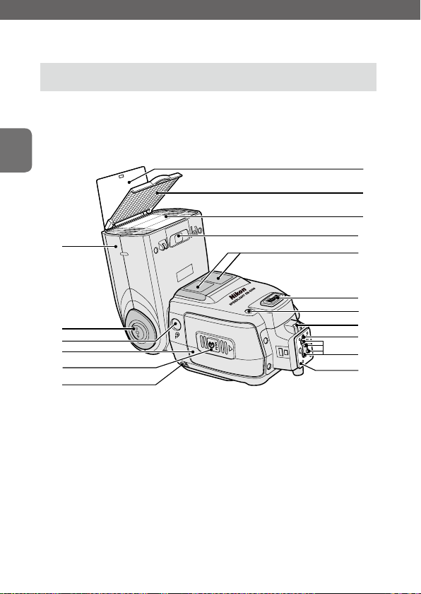
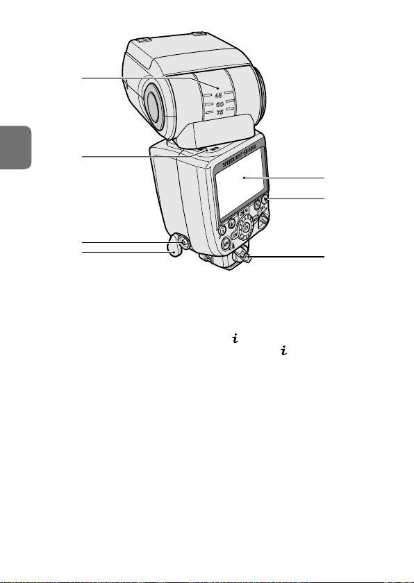
Speedlight Parts
B
Operation
7
8
9
1
2
3
4
5
6
10
11
12
13
14
15
16
17
B-1

1 Flash head
2 Flash head tilting/rotating
lock release button (0B-18)
3 Light sensor window for
wireless remote flash (0D-25)
4 Battery-chamber cover
5 Battery-chamber cover lock
release (0B-14)
6
7 Built-in bounce card (0E-4)
8 Built-in wide panel (0E-6)
9 Flash panel
10 Filter detector (0E-10)
11 AF-assist illuminator (0E-13)
indicator
12 External power source
terminal (supplied with
cover) (0F-13)
13 Light sensor for non-TTL auto
flash (0C-6)
14 External AF-assist illuminator
contacts
15 Locking pin
16 Accessory shoe contacts
17 Mounting foot
B
Operation
B-2
18
B
19
Operation
20
21
18 Flash head tilting angle scale
19 Flash head rotating angle
scale
20 Sync terminal
21 Sync terminal cover
22 LCD panel (0B-5)
23 Flash-ready indicator (0B-21,
D-29)
24 Mounting foot lock lever
(0B-16)
22
23
24
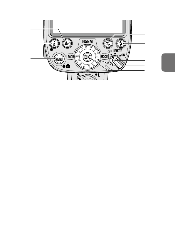
25 Modeling illumination button
• Controls modeling
illumination (0E-14)
26
button
• Displays menu settings
(0B-9)
27 MENU button
• Displays menu settings
(0B-22)
B-3
25
26
28
29
27
28 Wireless setting button
• Selects control type
• Configurable items vary
depending on the position
of the power switch
REMOTE:
Optical control remote
mode
Direct remote mode
Radio control remote
mode
ON:
Single flash-unit mode
Optical control master
mode
Radio control master
mode
29 Test firing button
• Controls test firing (0E-13)
30 Power switch
• Rotate to turn power on
and off
• Set the index to choose the
desired function
REMOTE:
Remote mode
(0D-11)
ON:
Single flash-unit mode
(0B-18, C-1)
Master mode
(0D-9)
31 Rotary multi selector
• Selects flash mode or other
items (0B-6)
32 OK button
• Confirms selected setting
30
B
31
32
Operation
B-4
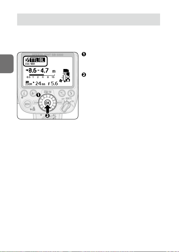
Settings and the LCD
Icons on the LCD show the status of settings. Displayed icons vary
according to selected flash modes and settings.
• The basic control of SB-5000 functions is as follows:
Use the rotary multi selector to
B
Operation
highlight the item to be configured
and choose desired setting.
Press the OK button to confirm
setting.
• Once confirmed, the highlighted
item returns to normal display.
• To return to normal display
without changing settings, press
the OK button.
• If the OK button is not pressed,
the highlighted item is selected
and returns to normal display after
8 seconds.
B-5
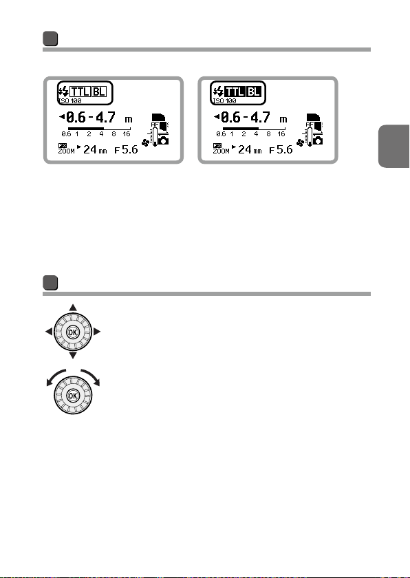
Normal and highlighted display
Normal display Highlighted display
Highlighted display indicates that the
item is being selected. Settings can be
changed while highlighted. The LCD
returns to normal display as shown at
the left after settings are changed and
confirmed.
Rotary multi selector
The rotary multi selector can be operated by pressing
up, down, left, right or by rotating it. In this user’s
manual, up, down, left, right on the rotary multi selector
are indicated as 1, 3, 4, 2.
B
Operation
B-6
■ Highlighting items
] Flash mode
[
Pressing the rotary multi selector 2
highlights the flash mode (0B-20).
B
[ ] Flash compensation value/Flash output level in
manual flash mode
Pressing the rotary multi selector 1
Operation
[ ] Zoom head position
highlights the flash compensation value
(0E-12).
This highlights the flash output level in
manual flash mode (0C-4).
Pressing the rotary multi selector 4
highlights the zoom head position
(0E-12).
• The zoom head position is
automatically set to match the lens
focal length when the SB-5000 is
attached to a camera.
B-7
■ Selecting items
Pressing the rotary multi selector 1 3 4 2 highlights the items to be
configured.
In menu and other menus, items can be selected by rotating the rotary
multi selector (0B-9, B-22).
■ Changing settings
Rotating the rotary multi selector changes the settings for highlighted
items.
• For numerical values, rotating the rotary multi selector clockwise
increases the value, and rotating it counterclockwise decreases the
value.
B
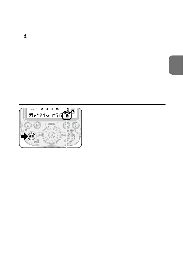
t Activating key lock
Key lock icon
Operation
Press the MENU button for 2 seconds. The
key lock icon appears on the LCD and the
dial and buttons are locked.
• The power switch, the test firing
button and the modeling illumination
button remain unlocked.
• To cancel key lock, press the MENU
button again for 2 seconds.
B-8
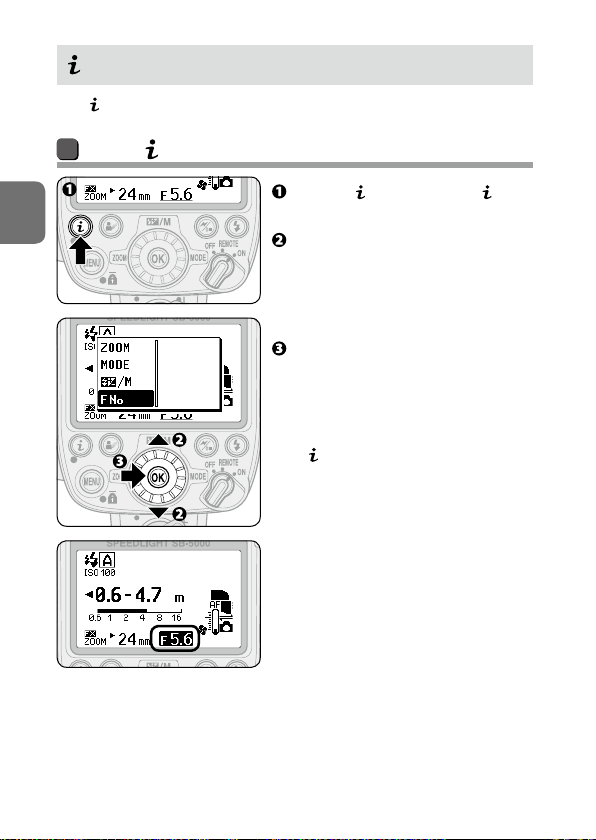
Menu
With menu, items to be configured can be selected.
Using menu
Press the button to display
B
Operation
menu.
Press the rotary multi selector
13 to highlight the item to be
configured.
• Alternatively, rotate the rotary
multi selector to select items.
Press the OK button to confirm
the selection.
• Alternatively, press the rotary
multi selector 2 to confirm the
selection.
•
item is highlighted. Use the rotary
multi selector to change settings
(0B-6).
menu is closed and the selected
B-9
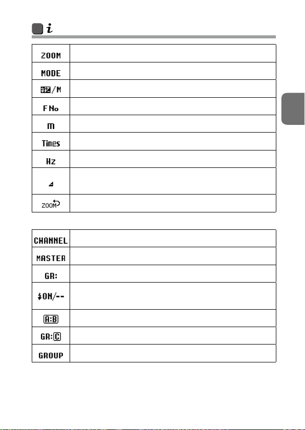
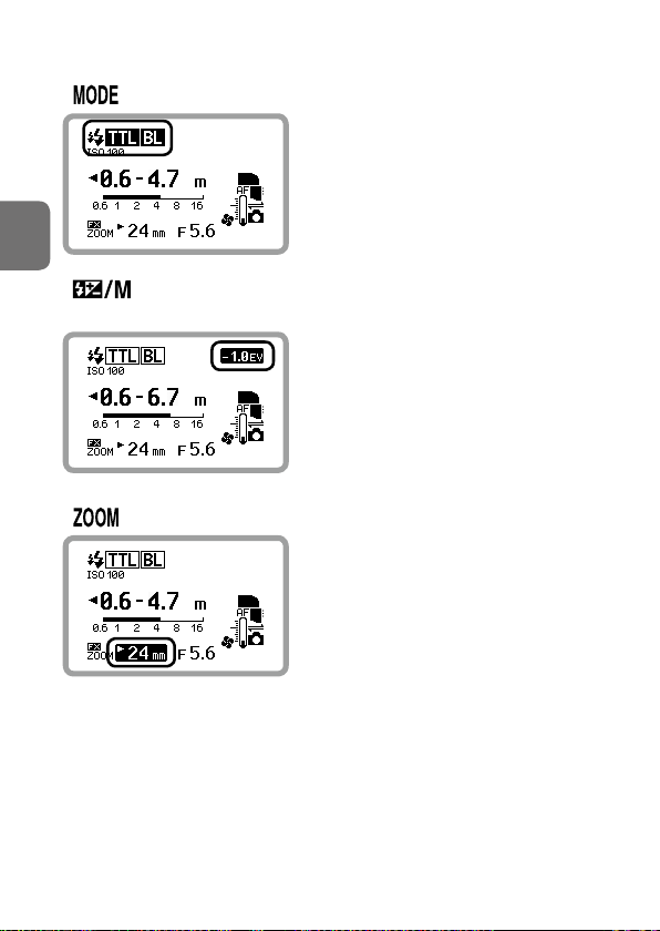
menu functions and settings icons
Zoom head position
Flash mode
Flash compensation value/Flash output level in manual ash mode
Aperture (in non-TTL auto ash mode)
Flash-to-subject distance (in distance-priority manual ash mode)
Number of ash rings (in repeating ash mode)
Frequency of ash rings (in repeating ash mode)
Amount of underexposure due to insucient ash output
(in i-TTL mode, underexposure occurred)
Activate power zoom function
[With wireless multiple flash-unit photography]
Channels
Master ash unit setting
Remote ash unit group setting (in master mode)
Flash function activated/canceled status in multiple ash-unit
repeating ash mode
Group A, B setting (quick wireless control)
Group C setting (quick wireless control)
Remote ash unit group setting (in remote mode)
• Displayed items vary depending on function, flash mode and camera in
use.
B
Operation
B-10
t Two-button reset
B
Operation
Press the MENU button and the
button simultaneously for 2 seconds to
reset all settings except menu settings
to default.
• This resets only the settings for the
item to which the power switch is set.
• When reset is complete, the LCD
is highlighted and then returns to
normal display.
B-11

Unified Flash Control
When the SB-5000 is attached to a camera compatible with unified flash
control, flash function settings can be shared by the SB-5000 and the
camera. While the SB-5000 settings can be configured on the camera, the
settings configured on the SB-5000 are also applied to the camera. The
following settings can be configured.
■ Single flash-unit mode
• Flash mode
• Flash compensation value/flash output level in manual flash mode
• Flash-to-subject distance (in distance-priority manual flash mode)
• Number and frequency of flash firings (in repeating flash mode)
■ Master mode
• Wireless flash options
• Remote flash control
• Flash function settings of each flash unit
• Channel (with optical control)
B
Operation
B-12
SB-5000
←
B
Operation
Flash function settings
for remote flash units are
changed on the SB-5000.
• If flash function settings are made on the SB-5000 when not attached to
a camera, the configured settings will be applied to the camera after the
SB-5000 is attached.
→
Settings are
shared.
Camera
Changed settings are
applied to the camera.
B-13
Basic Operations
This section covers basic procedures in i-TTL mode in combination with a
CLS-compatible camera.
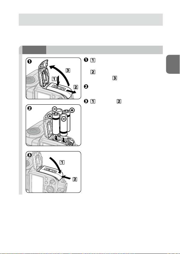
STEP
Inserting the batteries
1
While pressing the battery-
Insert the batteries following the
Push and slide the battery-
chamber cover lock release,
slide the battery-chamber
cover and open it.
[+] and [−] marks.
chamber cover to close it.
B
Operation
B-14
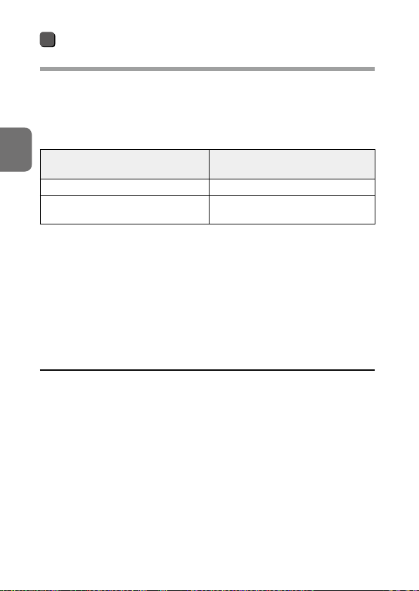
Compatible batteries and replacement/
recharging
When replacing batteries, use 4 fresh AA-size batteries or fully-charged
rechargeable batteries of the same brand. Refer to the following table to
determine when to replace batteries with fresh ones or recharge batteries
according to how long the flash-ready indicator takes to come on. Do not
mix old and new batteries or batteries of different types or makes.
B
1.5 V LR6 (AA-size) alkaline battery 20 s or more
1.2 V HR6 (AA-size) rechargeable Ni-MH
battery
Operation
• For minimum recycling time and number of flashes for each battery
type, refer to “Specifications” (0F-17).
• Alkaline battery performance may vary greatly depending on the
manufacturer.
• 1.5 V R6 (AA-size) carbon-zinc batteries are not recommended.
• Using an optional external power source increases the number of
flashes and provides shorter recycling times (0F-12).
Battery type
Time the flash-ready indicator
takes to come on
10 s or more
v Additional precautions regarding batteries
• Read and follow battery cautions in “For Your Safety” (0A-7 – A-10).
• Be sure to read and follow the warnings for the battery on the section,
“Notes on Batteries” (0F-8), before using the battery.
B-15

Low battery power indicator
When battery power is low, the icon
shown at the left appears on the LCD
and the SB-5000 stops functioning.
Replace or recharge batteries.
B
STEP
Attaching the SB-5000 to the camera
2
Make sure the SB-5000 and the
camera are turned off.
Make sure the mounting foot
lock lever is on the left (white
dot).
Slide the SB-5000’s mounting
foot into the camera’s accessory
shoe.
Turn the mounting foot lock lever
to L.
v Lock the Speedlight in place
Turn the mounting foot lock lever
clockwise until it stops at the mounting
foot lock index.
Operation
B-16

v Cameras with auto pop-up flash units
Turn the SB-5000 on when it is attached to a camera with a built-in, auto
pop-up flash unit. When the SB-5000 is turned off, the camera’s built-in
flash may pop-up automatically and strike the SB-5000. It is recommended
to detach the SB-5000 from the camera when not in use.
Detaching the SB-5000 from the camera
B
Operation
Make sure the SB-5000 and the
camera are turned off, turn the
mounting foot lock lever 90° to the
left, and then slide the SB-5000’s
mounting foot from the camera’s
accessory shoe.
• If the SB-5000’s mounting foot cannot
be removed from the camera’s
accessory shoe, turn the mounting
foot lock lever 90° to the left again,
and slide the SB-5000 slowly out.
• Do not forcibly remove the SB-5000.
B-17

STEP
Adjusting the flash head
3
While holding down the flash
head tilting/rotating lock release
button, adjust the flash head to
the forward-facing position.
• The flash head is locked when tilted
90° up or set in the forward-facing
position.
B
STEP
Turning the camera and SB-5000 on
4
Turn the camera on.
Set the SB-5000’s power switch to
[ON].
Operation
B-18

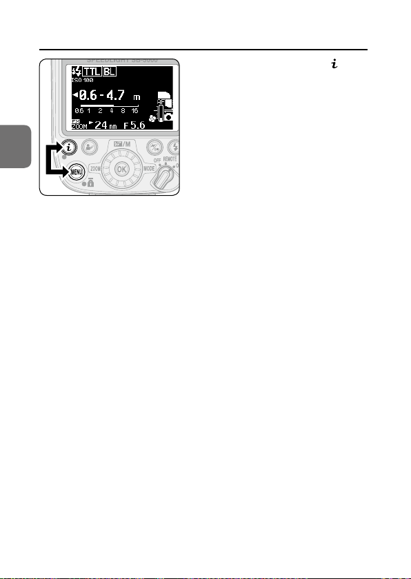
LCD example
• The image below is the SB-5000 LCD with the following settings: flash
mode: i-TTL; image area: FX format; illumination pattern: standard; ISO
sensitivity: 100; zoom head position: 24 mm; aperture f-number: 5.6
• Icons on the LCD may differ depending on the SB-5000 settings and the
camera and lens in use.
SB-5000 flash information
SB-5000 status icons
B
Monitor pre-flashes
ISO sensitivity
Effective flash output
Operation
distance range
FX format
Zoom head position
Aperture f-number
• (monitor pre-flashes) appears on the LCD when the SB-5000 is in
communication with a CLS-compatible camera.
• When the SB-5000 is in communication with the camera, ISO sensitivity,
effective flash output distance range, FX format/DX format, zoom
head position and aperture f-number are displayed depending on the
information received from the camera.
• An
above the indicator appears on the LCD when the zoom
head position is set manually.
• Some flash modes are only displayed when the SB-5000 is attached to
the camera.
Flash mode
Connected to a
CLS-compatible
camera
B-19

STEP
Selecting the flash mode
5
Press the wireless setting button
to choose single flash-unit mode.
Press the rotary multi selector
2 to highlight the flash mode.
Use the rotary multi selector to
display (0B-6).
Press the OK button.
B
Changing the flash mode
Pressing the rotary multi selector 1 2 or rotating it clockwise changes
the available flash mode icons displayed on the LCD.
• Pressing the rotary multi selector 3 4 or rotating it
counterclockwise changes the available flash mode icons displayed
on the LCD in reverse order.
• Only available flash modes are displayed on the LCD.
• Flash mode can also be configured in menu (0B-9).
B-20
Operation

B
Operation
Make sure that the flash-ready
indicator on the SB-5000 or in the
camera’s viewfinder is on before
taking a picture.
• Set the flash compensation value if
necessary (0E-12).
B-21

Menu Items and Settings
Various operations for the SB-5000 can be easily set using the LCD.
• Displayed icons vary according to the combination of camera and status
of the SB-5000.
• Depending on functions in use, some menu items and settings do not
function even though they can be configured and set (for example, flash
mode deselection in remote mode). Such items are indicated with grid
marks on both sides.
Menu settings
B
Press the MENU button to
display the menu settings
screen.
Press the rotary multi selector
4 to highlight the menu tabs.
Press the rotary multi selector
1 3 to highlight the menu tab
to be configured, and then press
the OK button.
Press the rotary multi selector
1 3 to highlight the menu item
to be configured, and then press
the OK button.
• Press the rotary multi selector
4 to return display to menu tab
selection.
Operation
B-22

B
Operation
Item being configured
Menu tabs
Press the rotary multi selector
1 3 to highlight the desired
setting, and then press the OK
button.
• Press the rotary multi selector
4 to return display to menu item
selection.
Press the MENU button to close
the menu settings.
• The LCD returns to normal display.
• Alternatively, rotate the rotary multi
selector to select items.
• Alternatively, press the rotary multi
selector 2 to confirm the selection.
:
2
Current setting
Setting being selected
Available selection
Items indicated with grid marks can
be configured but do not affect flash
operation.
B-23

Available menu functions and settings
(Bold: default)
Custom menu
Settings for photography
Flash mode deselection (0B-20, C-1)
Uncheck ash modes not necessary for single ash-unit
photography.
The mode in use cannot be deselected. i-TTL mode
cannot be deselected.
i-TTL mode
Auto aperture ash mode
Distance-priority manual ash mode
Manual ash mode
Repeating ash mode
Press the rotary multi selector 2 to uncheck and check the check
.
boxes
Non-TTL auto ash mode option (0C-6)
Auto aperture ash with monitor pre-ashes
Auto aperture flash without monitor pre-flashes
FX/DX format selection
Enables selection of image area settings when the zoom
head position is manually set
FX DX: Automatically set according to the camera’s
image area
FX: Nikon FX format (36 × 24)
DX: Nikon DX format (24 × 16)
B
Operation
B-24

B
Operation
AF-assist illumination/canceling ash function
(0E-13)
ON: Both AF-assist illumination and ash function activated
OFF: AF-assist illumination canceled, ash function activated
AF ONLY: AF-assist illumination activated, ash function canceled
(only AF-assist illuminator lights up)
ISO sensitivity manual setting
Enables manual setting of ISO sensitivity within the range
of 3 to 8000 when ISO sensitivity information has not
been received from the camera (non-CLS compatible SLR
camera is in use)
100: ISO 100
Reset custom settings
YES: Reset to default
NO: Do not reset
B-25

Wireless item menu
Settings for wireless multiple flash-unit photography using radio control
Channel setting (0D-12)
CH5
CH10
CH15
Link mode setting (0D-13)
PAIRING: Pairing
PIN: PIN code
Pairing (0D-15)
EXECUTE: Start pairing
PIN code setting
Displays current 4-digit PIN code. PIN codes can also be
entered with the rotary multi selector.
0000
Remote ash unit name (0B-27, D-11)
Displays registered name in remote mode. Up to
8 characters can be entered.
SB-5000
B
Operation
B-26

Entering remote flash unit name
Select characters or function icons with the rotary multi selector, and then
press the OK button.
4: Back by
1character
2: Forward by
1character
B
Available characters
Operation
Setup menu
Basic settings to make using the SB-5000 easier
Illumination pattern (0E-1)
CW: Center-weighted
STD: Standard
EVEN: Even
Test ring ash output level in i-TTL mode (0E-13)
M1/128: Approx. 1/128
M1/32: Approx. 1/32
M1/1: Full
DEL: Delete
OK: Confirm entry
B-27

Canceling power zoom function
ON: Power zoom function canceled (zoom head position must be
manually set)
OFF: Power zoom function activated (manual setting of
zoom head position not possible)
Zoom head position in bounce ash photography
TELE: Locked at the maximum telephoto position
WIDE: Locked at the maximum wide-angle position
OFF
Cooling system (0E-17)
Enables activation and canceling of the cooling system.
Select ON for continuous ash ring.
ON: Automatic control activated
OFF: Automatic control canceled
LCD panel contrast (0F-9)
Displays contrast levels on the LCD in a 9-step graph
5 levels in 9 steps
B
Operation
B-28

B
Flash-ready indicator and AF-assist illuminator in
remote mode (0D-29)
Enables selection of ash/light up of ash-ready indicator
and AF-assist illuminator in remote mode to save power
ALL: Back indicator lights up, front illuminator ashes slowly in
remote mode
REAR: Only back indicator lights up
FRONT: Only front illuminator ashes slowly in remote mode
Sound monitor (0D-29)
ON
OFF
Operation
Standby function (0E-15)
Enables adjustment of the time before the standby
function is activated
AUTO: Standby function activated when the time interval on
the camera’s standby timer* expires
40: 40 s
80: 80 s
160: 160 s
300: 300 s
: Standby function canceled
* The standby timer is called “auto meter o” on some camera models.
B-29

LCD panel illumination (0F-9)
Enables activation and canceling of LCD panel illumination
ON: Activated
OFF: Canceled
Measurement unit (m/ft)
m: meters
ft: feet
Version of rmware
14.001
Reset setup menu settings
Resets setup menu settings to default
YES
NO
B
Operation
B-30

Flash Modes
This section explains the SB-5000 flash modes.
• Use the rotary multi selector to change the flash mode (0B-20).
• Flash mode can also be configured in
t Auto setting of ISO sensitivity, aperture and focal length
When using the SB-5000 with a CLS-compatible camera and a CPU lens,
ISO sensitivity, aperture and focal length are automatically set according to
the lens and camera information.
• For details about ISO sensitivity range, see the camera user's manual.
C
• Flash compensation value can be set on the SB-5000. Press the rotary
multi selector 1 to highlight the flash compensation value and rotate
the rotary multi selector to choose a flash compensation value.
Flash Modes
menu (0B-9).
C-1

i-TTL Mode
Information obtained by monitor pre-flashes and exposure control
information are integrated by the camera to automatically adjust flash
output levels.
• i-TTL mode is recommended for standard photography.
• To take pictures using the SB-5000 in i-TTL mode, see “Basic Operations”
(0B-14).
• Either the i-TTL balanced fill-flash mode or the standard i-TTL mode
option is available.
• Use auto aperture flash or non-TTL auto flash mode for a camera that is
not compatible with i-TTL mode.
i-TTL balanced fill-flash
The flash output level is automatically adjusted for well-balanced exposure
of the main subject and background. appears on the LCD. The
i-TTL balanced fill-flash can be selected only when the SB-5000 is attached
to a camera.
Standard i-TTL
The main subject is correctly exposed regardless of background
brightness. This is useful when you want to highlight the main subject.
appears on the LCD.
C
Flash Modes
C-2

t Camera’s metering mode and i-TTL mode
When the camera’s metering mode is changed to spot metering while
i-TTL balanced fill-flash is in use, the i-TTL mode automatically changes to
the standard i-TTL mode.
i-TTL mode LCD example
: Monitor pre-flashes
: i-TTL
: Balanced fill-flash
C
Effective flash output distance range in i-TTL mode
The effective flash output distance
Flash Modes
This icon means that the flash
output cannot be effectively
adjusted for a shorter distance.
range is indicated by numbers and a bar
chart on the LCD.
• The actual flash-to-subject distance
should be within the range displayed.
• The range varies depending on
the camera’s image area setting,
illumination pattern, ISO sensitivity,
zoom head position and aperture.
C-3

Manual Flash Mode
In manual flash mode, aperture and flash output level are manually
selected. This allows for control of exposure and flash-to-subject distance.
• The flash output level can be set from M1/1 (full output) to M1/256 to
suit creative preferences.
• Monitor pre-flash and the indication of insufficient flash output for
correct exposure are not available in manual flash mode.
Manual flash mode LCD example
Flash output level
Effective flash output
distance (numerical
indicator)
Effective flash output
distance (▼)
C
Flash Modes
C-4

Taking a picture in manual flash mode
Press the rotary multi selector
1 to highlight the flash output
level.
Use the rotary multi selector
to choose a flash output level,
and then press the OK button
(0B-6).
• Flash output level can also be
C
configured in
• The flash-to-subject distance
indicated matches the selected
flash output level and aperture.
Check that the flash-ready
indicator is on, and then shoot.
Flash Modes
t When no lens aperture information is transmitted
When lens aperture information is not
transmitted to the SB-5000, aperture
can be set in menu.
Aperture; underlined when
aperture is set on the SB-5000
menu (0B-9).
C-5

Auto Aperture Flash Mode
The SB-5000’s light sensor for non-TTL auto flash measures the flash that
is reflected on the subject, and the SB-5000 controls the flash output level
according to the lens and camera information transmitted to the SB-5000,
including ISO sensitivity, exposure compensation value and aperture.
• When no aperture information is transmitted to the SB-5000, the flash
mode is automatically set to non-TTL auto flash.
Non-TTL Auto Flash Mode
The SB-5000’s light sensor for non-TTL auto flash measures the flash that
is reflected on the subject, and the SB-5000 controls the flash output level
according to the reflected flash data.
C
Distance-priority Manual Flash Mode
In this flash mode, when the flash-to-subject distance value is entered, the
SB-5000 automatically controls flash output level according to the camera
settings.
C-6
Flash Modes

Repeating Flash Mode
In repeating flash mode, the SB-5000 fires repeatedly during a single
exposure, creating stroboscopic multiple-exposure effects.
• Be sure to use fresh or fully charged batteries and allow enough time for
the flash unit to recycle between each repeating flash session.
• Because of the lower shutter speeds, use of a tripod is recommended to
prevent camera/flash unit shake.
• Indication of insufficient flash output for correct exposure is not
available in repeating flash mode.
C
Flash Modes
C-7

Wireless Multiple Flash-unit Photography
In wireless multiple flash-unit photography, multiple flash units fire
simultaneously. Different flash unit positions and function settings provide
diverse lighting effects.
With the SB-5000, wireless multiple flash-unit photography using optical
control or radio control is possible.
• In wireless multiple flash-unit photography, the Speedlight attached to
a camera is the master flash unit. Other Speedlights function as remote
flash units.
SB-5000 Wireless Multiple Flashunit Photography Examples
■ Using radio control
Remote flash unit (SB-5000)
SB-5000 and WR-R10
attached to camera
Setting the flash functions
on the SB-5000 attached to
a camera
Remote flash unit (SB-5000)
WR-R10 attached to camera
Setting the flash functions
on a camera
D
Wireless Multiple Flash-unit Photography
D-1

■ Using optical control
Remote flash unit
SB-5000 attached to camera
Setting the flash functions
on the SB-5000 attached to
a camera
D
Remote flash unit (SB-5000)
Speedlight* other than
SB-5000 when attached to camera
Setting the flash functions
on a Speedlight other than
an SB-5000 when attached
to a camera
Remote flash unit (SB-5000)
Camera
Setting the flash functions
on a camera
Remote flash unit (SB-5000)
Speedlight* other than
SB-5000 when attached to camera
Using direct remote
wireless multiple flash-unit
photography
* A model with the master flash function such as SB-910
Wireless Multiple Flash-unit Photography
D-2

■ Using optical control and radio control concurrently
Radio control remote
flash unit (SB-5000)
Optical control
remote flash unit
* A model with the master flash function such as SB-910
• For master flash unit setting, see D-9.
• For remote flash unit setting, see D-11.
Combination of WR-R10 and Speedlight*
other than SB-5000 attached to camera
D
Wireless Multiple Flash-unit Photography
D-3

SB-5000 Wireless Multiple Flashunit Photography Using Radio
Control
With the SB-5000, Advanced Wireless Lighting using radio control is
possible. Because communication is possible within a range of 30 m (98 ft)
and the light sensor window for wireless remote flash on remote flash units
does not have to face the master flash unit, positioning of flash units is more
flexible than with optical control. Up to 6 groups, total of 18 remote flash units
can be set up, expanding creative expression. In addition, wireless multiple
flash-unit photography in bright daylight, which is difficult with optical
control, is also possible as sunlight has no effect.
Compatible camera, the Wireless Remote Controller WR-R10
D
and the WR adapter WR-A10 (both optional) are required for
wireless multiple flash-unit photography using radio control.
For details, see the respective user’s manuals.
• Only the SB-5000 can be used as a remote flash unit.
• Up to 6 groups of remote flash units (A, B, C, D, E, F) can be set up,
but only 3 groups of remote flash units (A, B, C) can be set with quick
wireless control.
• Single or multiple remote flash units can be allocated for 1 group.
• The master flash unit and each remote flash unit group can operate with
a flash compensation value that is different to the other flash units or
groups. In group flash mode, they can also operate with different flash
modes.
Wireless Multiple Flash-unit Photography
D-4

SB-5000 Wireless Multiple Flashunit Photography Using Optical
Control
With the SB-5000, Advanced Wireless Lighting and direct remote wireless
multiple flash-unit photography (remote mode only) are possible using
optical control.
• Advanced Wireless Lighting is recommended for standard multiple
flash-unit photography.
• Direct remote wireless multiple flash-unit photography is particularly
suited to photographing fast-moving subjects.
■ Advanced Wireless Lighting
• A Speedlight compatible with Advanced Wireless Lighting (SB-5000,
SB-910, SB-700, SB-500, etc.) can be used as a remote flash unit.
• Up to 3 groups of remote flash units (A, B, C) can be set up.
• Single or multiple remote flash units can be allocated for 1 group.
• The master flash unit and each remote flash unit group can operate with
a flash compensation value that is different to the other flash units or
groups. In group flash mode, they can also operate with different flash
modes.
D
Wireless Multiple Flash-unit Photography
D-5

■ Direct remote wireless multiple flash-unit photography
• This is the same as the “SU-4 type wireless multiple flash-unit
photography” of the SB-910 and SB-700.
• The camera’s built-in flash or the Speedlight attached to the camera can
be used as the master flash unit.
• Be sure to cancel the master flash unit monitor pre-flash function or
select a master flash unit flash mode that does not activate monitor preflashes.
• The flash mode is set on each remote flash unit. Set the same flash
mode on each remote flash unit when using multiple remote flash units.
Using optical control and radio control concurrently is also possible.
For details, see D-27.
D
Wireless Multiple Flash-unit Photography
D-6

SB-5000 Functions for Wireless Multiple Flash-unit Photography
Flash
photography
with
Advanced
Wireless
Lighting
When used in
master mode
• Group ash
i-TTL
Auto aperture ash
Manual ash
Flash mode
Flash exposure
compensation
Group Up to 6 groups (A, B, C, D, E, F)
Radio
Channel* 3 channels (CH5, CH10, CH15)
control
Link mode Pairing, PIN code
Group Up to 3 groups (A, B, C)
Optical
control
Channel* 4 channels (1 – 4)
Flash function
canceled
• Quick wireless
control
• Multiple ash-unit
repeating ash
Possible
When used in
remote mode
The ash mode is set
on the master ash
unit (each group can
re with a ash mode
dierent to other
groups in group ash
mode)
The ash
compensation value
is set on the master
ash unit (each
group can re with a
compensation value
dierent to other
groups)
D
Wireless Multiple Flash-unit Photography
D-7

When used in
master mode
Direct
remote
wireless
multiple
ash-unit
photography
* Use only 1 channel from among these. Remote ash units can be triggered by other
master ash units. Use a dierent channel number if another photographer is using
the same type of wireless remote ash setup close by.
Flash mode –
Flash exposure
compensation
– –
When used in
remote mode
• AUTO (auto)
• M (manual)
• OFF (ash function
canceled)
v Notes on canceling the master flash unit flash function
With optical control, when the master flash unit flash function is canceled
and only the remote flash units fire, the master flash unit emits a number
D
of weak light signals to trigger the remote flash units. This operation will
normally not affect the correct exposure of the subject, although the
exposure might be affected if the subject is close and a high ISO sensitivity
has been set. To limit this effect, tilt the master flash unit’s flash head
upward.
Wireless Multiple Flash-unit Photography
D-8

Setting the Master Flash Unit
Setting the flash functions of each Speedlight on the SB-5000 attached to
a camera:
Set the power switch to [ON].
Press the wireless setting button
to choose radio or optical control
master mode.
Press the rotary multi selector
2 on the master flash unit to
display the desired flash mode.
Control type information
Optical
control
Radio
control
Flash mode
Group ash
Quick wireless control
Multiple ash-unit repeating ash
D
Wireless Multiple Flash-unit Photography
D-9

Master mode LCD example (radio control, group flash)
Master flash unit flash mode and flash compensation value
: Appears when ready to fire
Remote flash unit flash mode (--: flash function
canceled) and flash compensation value
Master flash unit zoom head position
D
Wireless Multiple Flash-unit Photography
D-10

Setting a Remote Flash Unit
Set the power switch to
[REMOTE].
Press the wireless setting button
to choose radio control, optical
control or direct remote mode.
• When using radio control, the
remote flash unit name and link
mode are displayed.
Control type information
Optical control remote mode
Direct remote mode
Radio control remote mode
Remote mode LCD example (radio control)
Remote flash
unit name
Link mode
Group
Channel
Remote flash unit zoom head
position
Remote mode
Flash mode (--: flash
function canceled)
Sound monitor
D
Wireless Multiple Flash-unit Photography
D-11

Preparation for Photography
Radio control only
Setting the link for radio control
When using radio control, set the link in the wireless item menu.
• Set the SB-5000 in radio control remote mode before setting the link
(0D-11).
STEP
Setting the channel
1
Check the channel set on the
WR-R10.
• For details about WR-R10 settings,
D
Choose [CHANNEL] from the
wireless item menu (0B-22).
Press the rotary multi selector
1 3 to choose the same channel
as the WR-R10, and then press
the OK button.
Wireless Multiple Flash-unit Photography
D-12
see the WR-R10 user’s manual.

STEP
Setting the link mode
2
Check the link mode set on
the camera with the WR-R10
attached.
• For details about how to check the
link mode, see the camera user’s
manual.
Choose [LINK MODE] from the
wireless item menu (0B-22).
Press the rotary multi selector
1 3 to choose the same link
mode as the camera with the
WR-R10 attached, and then press
the OK button.
D
D-13
Wireless Multiple Flash-unit Photography

t Pairing
• Execute pairing beforehand between devices that conduct
communication.
• Once the SB-5000 and the WR-R10 are paired, it is not necessary to pair
them again.
• To use multiple SB-5000 units, each unit must be paired with the
WR-R10.
• When another WR-R10 is attached to the camera, re-execute pairing
with it.
t PIN code
• Set the same PIN code beforehand for devices that conduct
communication.
• To use multiple SB-5000 units, set the same PIN code for all SB-5000
D
units and the WR-R10. The PIN code of the WR-R10 can be set on the
camera.
• To increase the number of SB-5000 units, the link can be established
only by entering the same PIN code to all the units to be added.
• Even when another WR-R10 is attached to the camera, resetting the PIN
code is not necessary.
Wireless Multiple Flash-unit Photography
D-14

STEP
■ When link mode is set to pairing
Setting the link
3
Choose [PAIR] from the wireless
item menu (0B-22).
Check that [EXECUTE] is
highlighted, and then press the
OK button while pressing the
pairing button on the WR-R10
attached to the camera.
• An execution indicator appears on
the LCD and the
flashes slowly in green while
pairing.
indicator
D
D-15
Wireless Multiple Flash-unit Photography

Check that pairing has
succeeded.
• When pairing succeeds, a
completion indicator appears on
the LCD and the
flashes slowly in green and orange.
Pairing succeeded
Pairing failed
• When pairing fails, an error
indicator appears on the LCD.
Check the channel setting and try
again.
• For details about WR-R10 settings, see
the WR-R10 user's manual.
D
For link setting with PIN code, see the Speedlight reference manual,
which can be downloaded from the Nikon website.
indicator
Wireless Multiple Flash-unit Photography
D-16

Advanced Wireless Lighting
With the SB-5000, 3 Advanced Wireless Lighting options are available:
group flash, which enables desired flash function settings for each flash
unit; quick wireless control, with easy setting for wireless multiple flashunit photography; and multiple flash-unit repeating flash.
Group flash
In group flash mode, the master flash unit and each remote flash unit
group can operate with a flash compensation value and a flash mode that
is different to the other flash units or groups.
• Group flash mode can be selected by pressing the rotary multi selector
2 when using the SB-5000 as the master flash unit.
• Setting the flash functions of each Speedlight on the camera is also
possible.
D
D-17
Wireless Multiple Flash-unit Photography

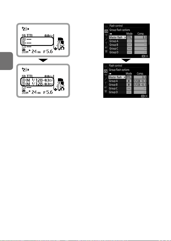
Taking a picture with Advanced Wireless
Lighting
1. Master flash unit setting
Setting the flash functions of each Speedlight on the SB-5000:
Press the rotary multi selector
3 on the master flash unit to
highlight (master flash unit).
Rotate the rotary multi selector
to choose a master flash unit
flash mode.
Press the rotary multi selector
2 to highlight the flash
D
Press the rotary multi selector 4 to highlight the flash mode,
and then press the OK button.
Press the rotary multi selector 3 to highlight (group A).
Repeat procedures , and to set the flash mode and flash
compensation value of remote flash unit group A.
Set the other remote flash unit groups in the same manner.
compensation value and rotate
the rotary multi selector to
choose a flash compensation
value.
Wireless Multiple Flash-unit Photography
D-18

With optical control only
Choose [CHANNEL] in menu
(0B-9).
•
Press the button to display
menu and use the rotary
multi selector to choose
[CHANNEL].
Use the rotary multi selector to
choose a channel, and then press
the OK button (0B-6).
• Flash mode and flash compensation
value can also be configured in
menu (0B-9).
D
D-19
Wireless Multiple Flash-unit Photography

2. Remote flash unit setting
• Group name and channel
number being set appears
larger.
D
Press the rotary multi selector
3 on the remote flash unit to
highlight the group, rotate the
rotary multi selector to choose a
group, and then press the OK
button.
• Alternatively, press the rotary multi
selector 4 2 to choose a group.
Press the rotary multi selector
3 to highlight the channel,
rotate the rotary multi
selector to choose a channel, and
then press the OK button.
• Alternatively, press the rotary multi
selector 4 2 to choose a channel.
With radio control
• Be sure to choose the same
channel number as set on the
Wireless Remote Controller
WR-R10.
With optical control
• Be sure to choose the same
channel number as set on the
master flash unit.
Wireless Multiple Flash-unit Photography
D-20

Press the rotary multi selector
4 to highlight the zoom head
position, use the rotary multi
selector to choose a zoom head
position, and then press the
OK button (0B-6).
Check the status of the flash
units, and then shoot.
• Group, channel and zoom head
position can also be configured in
menu (0B-9).
t Setting the flash functions on a camera
Use camera menu to make settings.
• For details, see the camera user’s
manual.
D
D-21
Wireless Multiple Flash-unit Photography

Quick wireless control
The flash output level ratios of 2 remote flash unit groups (A and B) and
the flash function activate/cancel of group C can be easily set with quick
wireless control.
• Quick wireless control can be selected by pressing the rotary multi
selector 2 when using the SB-5000 as the master flash unit.
• The master flash unit does not fire in quick wireless control photography.
Multiple flash-unit repeating flash
Multiple flash-unit repeating flash photography is possible in Advanced
Wireless Lighting.
• Multiple flash-unit repeating flash mode can be selected by pressing the
rotary multi selector 2 when using the SB-5000 as the master flash unit.
D
For direct remote wireless multiple flash-unit photography, see the
Speedlight reference manual, which can be downloaded from the
Nikon website.
Wireless Multiple Flash-unit Photography
D-22

Setting up Remote Flash Units
• Place all remote flash units in the same group close together and facing
the same direction.
• Use the provided Speedlight Stand AS-22 for stable positioning of the
remote flash units. Attach and detach the SB-5000 to and from the
AS-22 in the same way it is attached to/detached from the camera’s
accessory shoe.
• When carrying the Speedlight Stand with the SB-5000 attached, be sure
to hold the SB-5000 in your hand.
• Be sure to check the status of the flash units before photographing.
• Set the zoom head position of the remote flash units wider than the
angle of view, so that the subject will receive sufficient illumination even
when the angle of the flash head is off axis from the subject. When the
flash-to-subject distance is very short, set the zoom head position wide
enough to achieve sufficient light.
D
D-23
Wireless Multiple Flash-unit Photography

■ When using radio control
• As a basic guide, the effective distance between the master and remote
flash units is approx. 30 m (98 ft) or less. These ranges vary slightly
depending on ambient environment.
• Position the remote flash units facing the desired direction.
• Up to 18 remote flash units can be used together.
• Be sure to press the test firing button on the master flash unit attached
to a camera to test fire the remote flash units after setting up the
camera, WR-R10 and Speedlight.
• When radio control remote mode is set, the standby function is
canceled while communicating with the camera. Make sure that there
is sufficient battery power. When not communicating with the camera,
the standby function is automatically activated regardless of the standby
function setting in the setup menu (0B-22).
D
Less than approx.
30 m (98 ft)
Remote flash units
(SB-5000)
Remote flash units
(SB-5000)
SB-5000 and
WR-R10 attached to
camera
Less than approx.
30 m (98 ft)
Wireless Multiple Flash-unit Photography
D-24

■ When using optical control
• Position the remote flash units so that light from the master flash unit
can reach the light sensor window for wireless remote flash of the
remote flash units. This is particularly important when holding a remote
flash unit in the hand.
• Be sure to press the master flash unit test firing button to test fire the
remote flash units after setting up.
Remote flash units
D
Remote flash units
• As a basic guide, the effective distance between the master flash unit
and remote flash units is approx. 10 m (32 ft) or less in the front position,
and approx. 7 m (22 ft) at both sides (in Advanced Wireless Lighting).
These ranges vary slightly depending on ambient light.
Master flash unit
attached to camera
Wireless Multiple Flash-unit Photography
D-25

• There is no limit to the number of remote flash units that can be used
together. However, when using many remote flash units, light may be
unintentionally picked up by the light sensor of the master flash unit
and interfere with correct functioning. The practical number of remote
flash units for wireless multiple flash-unit photography is 3. In Advanced
Wireless Lighting, for practical purposes, the number of remote flash
units should be limited to around 3 for 1 group.
Less than
approx. 7 m (22 ft)
Group C
Less than
approx. 10 m
(32 ft)
Group B
D
Group A
Within 60°
Master flash unit
• Take care not to let light from the remote flash units enter the camera
lens or the master flash unit light sensor for non-TTL auto flash.
• Do not place an obstacle between the master flash unit and remote
flash units as it can interfere with transmission of data.
• When optical control remote mode is set, the standby function is
canceled. Make sure that there is sufficient battery power.
Wireless Multiple Flash-unit Photography
D-26

Using Optical Control and Radio Control Concurrently
The following combinations enable group flash using optical control and
radio control concurrently.
Master flash unit
(other than the SB-5000)
Optical control
with Speedlight
other than the
SB-5000
Remote flash units
Group A
Group B
Group C
Radio control
with camera
WR-R10 attached
to camera
■ Master flash unit (optical control)
Former Speedlight models with the master flash function, such as SB-910,
attached to a camera can be used as the master flash unit to control
remote flash unit groups A, B and C.
• The SB-5000 cannot be used as the master flash unit when using optical
control and radio control concurrently.
Group D
Remote flash units
Group E
Group F
D-27
D
Wireless Multiple Flash-unit Photography

■ Remote flash unit groups A, B and C (optical control)
Up to 3 groups of remote flash units (A, B, C) can be set up for optical
control.
• Former Speedlight model attached to a camera is the master flash unit.
• Choose optical control remote mode when using the SB-5000 as remote
flash unit in groups A, B and C.
■ Camera and WR-R10 (radio control)
Camera compatible with radio control with the WR-R10 attached controls
remote flash unit groups D, E and F.
• For details, see the camera user’s manual.
■ Remote flash unit groups D, E and F (radio control)
Up to 3 groups of remote flash units (D, E, F) can be set up for radio control.
• Camera with the WR-R10 attached controls the flash function.
• For details, see the camera user’s manual.
D
Wireless Multiple Flash-unit Photography
D-28

Checking Status in Wireless Multiple Flash-unit Photography
With wireless multiple flash-unit photography, the SB-5000’s flash-ready
indicator, AF-assist illuminator, sound monitor and LCD panel, as well as
indicator (radio control only) can be used to check the status before
and after taking a picture.
• The sound monitor can be used to check the operational status of a
remote flash unit. This function can be activated or canceled in the
setup menu (0B-22).
• When the SB-5000 is used in remote mode, the flash-ready indicator and
the AF-assist illuminator can be turned off in the setup menu to reduce
power consumption. In default setting, only the flash-ready indicator
lights up (0B-22).
D
D-29
Wireless Multiple Flash-unit Photography

Master flash unit
Flash-ready
indicator
LCD panel Status
D
Lights up
Goes out
and lights up
when ready
to re
Flashes slowly
for approx. 3 s
Does not light
up or ash
(radio control only)
– Fired properly
Ready to re
Underexposure due to insucient ash
output may have occurred.
To compensate, use a wider aperture
(smaller f-number) or higher ISO
sensitivity, or move the ash unit closer to
the subject and reshoot.
The camera is not compatible with radio
control. Check the camera in use.
Wireless Multiple Flash-unit Photography
D-30

Remote flash unit
Flash-ready
indicator
Lights up
Lights up
Flashes
quickly for
approx. 3 s
Lights up
AF-assist
illuminator
Flashes
slowly
Flashes
slowly or
does not
light up or
ash at all
Flashes
quickly for
approx. 3 s
Flashes
quickly for
approx. 6 s
Sound
monitor
1 long
beep
2 short
beeps
8 long
beeps
12 long
beeps in
2 dierent
tones
LCD panel Status
– Ready to re
– Fired properly
Underexposure due to
insucient ash output may
have occurred.
To compensate, use a wider
aperture (smaller f-number) or
higher ISO sensitivity, or move
the ash unit closer to the
subject and reshoot.
The remote ash unit light
sensor has failed to receive
the command.
With optical control, this is
because the light sensor
cannot detect when to stop
ring in sync with the master
–
ash unit, either due to a
reection from the remote
ash unit itself or light from
another remote ash unit that
may have entered the light
sensor window.
Change the direction or
position of the remote ash
unit and reshoot.
D
D-31
Wireless Multiple Flash-unit Photography

indicator
indicator
Lights up (green) In radio communication
Flashes slowly
(orange)
Proper communication is not possible.
Check the camera’s wireless setting.
Check if the same channel as the WR-R10 is set.
Check if the same link mode as the camera is set.
When link mode is set to PIN code, check if the same PIN code as
the camera is set.
D
Status
Wireless Multiple Flash-unit Photography
D-32

Functions
Switching Illumination Patterns
In flash photography, the center of the image is most illuminated, while
the edges are darker. The SB-5000 provides 3 types of illumination patterns
with different light falloff at edges. Select the suitable pattern according to
the photography environment.
Standard
The basic illumination pattern for common flash photography
environments
Even
The light falloff at the edge of the image is less than with the standard
illumination pattern.
• Suitable for group photographs, in which sufficient light is required
without light falloff at the edges.
Center-weighted
The center-weighted pattern provides larger guide numbers at the center
of the image than the standard illumination pattern (the light falloff at the
edge will be greater than the standard illumination pattern).
• Suitable for shots, such as portraits, in which the light falloff at the edge
of an image can be ignored.
E
Functions
E-1

Setting the illumination pattern
The illumination pattern can be
changed in the setup menu (0B-22).
• The selected illumination pattern is
E
Functions
indicated with an icon on the LCD.
Standard
Even
Center-weighted
E-2

Bounce Flash Operation
Bounce flash is a photographic technique using light that is bounced off a
ceiling or wall using a tilted or rotated flash head. This provides the effects
listed below compared to those with direct light from a flash unit:
• Overexposure to a subject that is closer than other subjects can be
reduced.
• Background shadows can be softened.
• Glare on faces, hair and clothes can be reduced.
• The shadows can be softened further using the Nikon Diffusion Dome.
Nikon Diffusion Dome
• By attaching the included Nikon Diffusion Dome over the flash head,
light can be further diffused during bounce flash photography to create
extremely soft light with virtually no shadow.
• The same effect can be achieved with the camera in either horizontal or
vertical position.
• Light is more effectively diffused when the built-in wide panel is used
(0E-6).
E
Functions
E-3

Attaching the Nikon Diffusion Dome
Attach the Nikon Diffusion Dome as
shown in the diagram, with the Nikon
logo facing up.
• Detach the Nikon Diffusion Dome
while pulling the detaching knob
outward.
Detaching knob
t Using the built-in bounce card
• In bounce flash photography, use the SB-5000’s built-in bounce card to
make a portrait subject’s eyes look more vibrant by reflecting the light
in them.
• Tilt the flash head up 90°.
Setting the built-in bounce card
Pull out the bounce card and the
E
Functions
built-in wide panel and, while holding
the bounce card, slide the built-in wide
panel back into place inside the flash
head.
• Pull out the bounce card until it stops
in the locked position.
• To insert the bounce card, pull out the
built-in wide panel again and slide
both back into place together.
E-4

Taking Close-up Photographs
When the flash-to-subject distance is less than approx. 2 m (6.5 ft), tilting
down the flash head is recommended to ensure sufficient illumination of
the lower part of the subject in close-up photography.
• The bounce-down icon appears when the flash head is tilted down.
• When using a long lens, be careful that the light from the flash is not
obstructed by the lens barrel.
• Vignetting may occur in close-up flash photography due to the
illumination pattern, lens in use, focal length setting, etc. Therefore,
make test shots if taking an important picture.
t Effect of the built-in wide panel
With the built-in wide panel, the flash from the SB-5000 is diffused. This
softens shadows and prevents glare on faces, etc.
E
Functions
E-5

Setting the built-in wide panel
Carefully pull the built-in
wide panel all the way out and
position it over the flash
panel.
Slide the bounce card back into
place inside the flash head.
• To replace the built-in wide panel,
lift it up and slide it into the flash
head as far as it will go.
t If the built-in wide panel is broken
• The built-in wide panel may break if subjected to strong knocks while on
E
the flash head.
• In this case, contact your retailer or Nikon-authorized service
representative.
Functions
E-6

Flash Photography with Color Filters
Color compensation filters, a fluorescent filter and an incandescent filter
are included with the SB-5000 for use with flash photography under
incandescent/tungsten and fluorescent lighting. The color of ambient light
and the flash light can be matched to provide natural color.
• Color filters (Color Filter Set SJ-5 and Color Filter Holder SZ-4) that
change the color of the light emitted by the SB-5000 are available
separately (0F-10).
Using color compensation filters and color
filters
Filters Purpose
Fluorescent lter (Fluorescent Filter
SZ-4FL), included
Incandescent lter (Incandescent
Filter SZ-4TN), included
Color lters (Color Filter Set SJ-5),
optional
t
Color compensation with included and optional filters
The included Incandescent Filter SZ-4TN and the optional SJ-5
incandescent filters TN-A1 and TN-A2 differ in color compensation. The
color of images taken with the SZ-4TN and SJ-5 incandescent filters are
slightly different even when the same light source is used. The color can
be adjusted with the camera’s white balance fine tuning.
Balance the color of light from the ash to
match that of uorescent lighting
Balance the color of light from the ash to
match that of incandescent or tungsten
lighting
Create interesting eects by changing the
color of the light emitted by the ash
E
Functions
E-7

How to attach color compensation filters
SZ
−
4FL
(included)
Place the filter on the flash head
and insert into the slit at the top.
• Place the filter with the Nikon
logo facing up, as shown in the
diagram.
Check the LCD.
• Filter type is displayed.
• The information is transmitted
from the SB-5000 to the camera.
E
Functions
E-8
Fluorescent filter
Incandescent filter

How to attach SJ-5 color filters (optional)
SZ
−
4FL
Fold along the line marked on
the filter.
Attach the filter to Color Filter
Holder SZ-4 (optional) as shown
in the diagram.
• Insert the filter edges into the slits
on the holder, and then align the
filter positioning hole with the
holder pin.
• Align the filter identification code
(silver marks) with the black bar on
the holder.
• Attach the filter to the filter holder
without creasing the filter or
leaving any gaps.
Place the filter holder on the
flash head with the Nikon logo
facing up, as shown in the
diagram, and insert it into the
slit at the top.
• Be sure to attach the filter to the
filter holder before placing the
filter holder on the flash head.
E
Functions
E-9

Check the LCD.
• The filter type is displayed.
• Be sure that nothing obstructs the
filter detector.
Red filter is attached
FL-G1 (uorescent lter) RED
FL-G2 (uorescent lter) BLUE
TN-A1 (incandescent lter) YELLOW
TN-A2 (incandescent lter) AMBER
• When the filter is not properly
attached, the warning indicator
E
shown left appears. Remove the filter
and reattach.
Functions
E-10
Warning indicator

v Notes on using SJ-5 color filters
• These filters are consumable items. Replace them when they deteriorate
or their colors fade.
• The heat generated from the flash head can warp the filters. However,
this will not affect their performance.
• Scratches on the filters will have no effect on performance unless the
filters fade in color.
• To remove dust or dirt, wipe the filter lightly with a soft, clean cloth.
Color compensation filters, color filters and
camera’s white balance settings
When a color compensation filter is attached to the SB-5000 while
the camera’s white balance is set to auto or flash, filter information is
automatically transmitted to the camera, and the camera’s optimum white
balance is automatically adjusted to give the correct color temperature.
• When an SJ-5 color filter is attached to the SB-5000, set the camera’s
white balance to auto, flash or direct sunlight.
• When using the SB-5000 with a camera not equipped with filter
detection (D2 series, D1 series, D200, D100, D80, D70 series, D60, D50,
D40 series), set the camera’s white balance according to the filter in use.
• For details about white balance, see the camera user's manual.
E
Functions
E-11

Flash Photography Support Functions
Flash exposure compensation
Exposure compensation for a flash-illuminated subject without affecting
background exposure can be achieved by adjusting the SB-5000’s flash
output level.
• Some plus compensation may be necessary to make the main subject
brighter, and some minus compensation to make it darker.
• Flash exposure compensation is possible in i-TTL, auto aperture flash,
non-TTL auto flash and distance-priority manual flash modes.
Power zoom function
The SB-5000 automatically adjusts the zoom head position to match the
lens focal length.
• Power zoom function is automatically activated when lens focal length
information is transmitted from the attached camera to the SB-5000.
• Zoom head positions that can be automatically adjusted differ
E
depending on the settings.
Functions
E-12

AF-assist illumination
When light is too low for normal autofocus operation, the SB-5000’s AFassist illumination enables autofocus photography.
• The SB-5000’s AF-assist illumination is compatible with the multi-point
AF system.
• AF-assist illumination cannot be used with non-CLS-compatible cameras
and COOLPIX cameras.
Test firing
Pressing the test firing button determines whether the SB-5000 fires
properly.
• The flash output level during test firing varies depending on settings
and flash mode.
• In master mode with wireless multiple flash-unit photography using
optical control, test firing of the SB-5000 is not possible. When the
master flash unit test firing button is pressed, the remote flash units test
fire one after another, beginning with group A.
• In master mode with wireless multiple flash-unit photography using
radio control, when the master flash unit test firing button is pressed,
the master flash unit test fires first, then the remote flash units test fire
one after another, beginning with group A.
E
Functions
E-13

Modeling illumination
When the modeling illumination button is pressed, the flash fires
repeatedly at a reduced flash output level. This is useful for checking the
glare and shadows cast on a subject before actually taking the picture.
• The flash fires as a modeling illuminator for up to approx. 1second.
• When the depth-of-field preview button on a camera compatible with
modeling illumination is pressed, the modeling illuminator fires. For
details, see the camera user’s manual.
■ Advanced Wireless Lighting (0D-17)
• When the master flash unit’s modeling illumination button is pressed,
the master flash unit fires as a modeling illuminator at a fixed flash
output level (except when the flash function is canceled).
• When the camera’s depth-of-field preview button is pressed, the master
flash unit and remote flash unit groups whose flash functions are
activated fire as modeling illuminators according to the set flash output
level and the selected mode.
With optical control only
E
• When a remote flash unit group is highlighted on the master flash unit
and the master flash unit’s modeling illumination button is pressed,
only the remote flash units in the selected group fire as modeling
illuminators (except group A and B in quick wireless control).
Functions
■ Direct remote wireless multiple flash-unit photography
• Modeling illumination is not possible.
E-14

Standby function
If the SB-5000 and camera are not
used for a specified time, the standby
function is automatically activated to
conserve battery power.
• The standby function is activated
when the time interval on the
camera’s standby timer* expires
(default setting). For details about the
standby timer, see the camera user's
manual.
• The standby activation lead time can be adjusted in the setup menu
(0B-22).
* The standby timer is called “auto meter off” on some camera models.
To cancel standby
• Press the camera’s shutter-release button halfway.
• Set the SB-5000’s power switch to a position other than [OFF].
• Press the SB-5000’s test firing button.
E
Functions
E-15

Thermal cut-out
The SB-5000 features a function that offers protection against damage
to the flash panel and body from overheating. This function does not
stop the flash head temperature rising. Be careful not to let the SB-5000
overheat during continuous flash use.
• The thermal cut-out indicator appears when the temperature of the
flash head rises as a result of the flash being fired numerous times in
quick succession. All operations except power ON/OFF and menu
settings are suspended to prevent heat damage to the flash panel and
body.
LCD at normal
temperature
E
• Wait until the SB-5000 cools down.
• Operation can be resumed once the warning is no longer displayed.
• On rare occasions, the thermal cut-out indicator might appear or
disappear without the temperature changing depending on the zoom
head position. This is not a malfunction.
Functions
Thermal cut-out indicator
High
temperature
E-16
 Loading...