

Nikon MONARCH 7 Riflescope Instruction Manual for customers in North America
In the event that you should require service for your Nikon RIFLESCOPE,
in case of USA market, please send it directly to:
Nikon Scope Service
6420 Wilshire Blvd Suite 100
Los Angeles, CA 90048-5501
1-800-Nikon SV.
In other market, please bring it to dealer from which you purchased it.
En
Fr
Si vous avez besoin de faire réparer votre lunette de visée Nikon,
apportez-la au magasin où vous l'avez achetée.
Manufacturer:
Printed in the Philippines (837C) 1E/1512
Imprimé en Les Philippines
2.5-10×50 SF 3-12×56 SF/SF IL 4-16×50 SF/SF IL
Instruction manual/Mode d’emploi

Congratulations on your choice of a Nikon MONARCH 7 Riflescope. Your new scope is the finest example of Nikon's rugged and durable construction and precision bright optics; important qualities for a serious shooter's
riflescope.
En
Whether you use your scope for hunting or for target shooting, the procedure for mounting is identical. A set of high-quality steel mounting rings which have a standard diameter of 30 mm (1.2 in.) are required to mount
the scope. Follow the ring manufacturer's instructions for mounting procedures. After mounting the scope on your rifle, follow the procedures for reticle alignment.
SUPPLIED ITEM(S)
Body ················································1 piece High profile turret ·····································2 pieces Cleaning cloth·················································································1 piece
Eyepiece cap*··································1 piece High profile turret cap ······························2 pieces Battery (3V Lithium battery: CR2032) (IL models only) ···············1 piece
Objective cap* ································ 1 piece Sunshade ··················································1 piece
* 3-12×56 SF IL, 4-16×50 SF IL: Rubber Band Linked (This type connects the objective and eyepiece caps using a rubber band.) 2.5-10×50 SF, 3-12×56 SF, 4-16×50 SF: Flip Open
En
IMPORTANT INFORMATION
IT IS IMPORTANT THAT YOUR NIKON RIFLESCOPE IS MOUNTED PROPERLY AND THAT CAREFUL CONSIDERATION BE GIVEN WHEN MOUNTING YOUR NIKON RIFLESCOPE ON A FIREARM.
WE HIGHLY RECOMMEND THAT YOUR NIKON RIFLESCOPE BE MOUNTED ON YOUR FIREARM BY AN EXPERIENCED, REPUTABLE GUNSMITH.
THE USER ASSUMES ALL RESPONSIBILITY AND LIABILITY FOR HAVING THE NIKON RIFLESCOPE PROPERLY MOUNTED TO A FIREARM AND USING THE NIKON RIFLESCOPE PROPERLY.
ALWAYS CHECK THE CONDITION OF YOUR MOUNTING SYSTEM PRIOR TO USING YOUR FIREARM.
Caution
(1) Do NOT look at the sun through the riflescope. It will permanently damage your eye. This precaution applies to all optical devices, such as cameras and binoculars.
(2) The riflescope is effectively sealed against moisture and dust. You may use your scope safely either in the rain or in dusty climates. To preserve the appearance of the scope, we recommend that it be dried and
cleaned prior to storage. Use a soft cloth for cleaning metal surfaces and use photographic lens tissue to clean the scope's lenses.
(3) Never leave the device in the sun for extended periods without the Eyepiece/Objective cap. The objective lens and eyepiece can function as a burning glass and damage the interior components.
(4) When not in use for an extended period, please remove the battery from the body.
(5) If the battery compartment cover is damaged, or if it emits a strange sound due to dropping or some other cause, remove the battery immediately and stop using.
2
3
En
Caution (Lithium battery)
If handled incorrectly, the battery may rupture and leak, corroding equipment and staining clothing. Be sure to observe the following:
• Install the battery with the + and - poles positioned correctly.
• The battery should be removed when exhausted or during extended periods of non-use.
• Do not short the end terminal of the battery chamber.
• Do not carry together with keys or coins in a pocket or bag, it may short and cause overheating.
• Do not expose the battery to water, or a flame. Never disassemble the battery.
• Do not charge the lithium battery.
• If liquid from a damaged battery comes into contact with clothing or skin, rinse immediately with plenty of water. If liquid from a damaged battery enters the eyes, rinse immediately with clean water, then consult a doctor.
• When disposing of the battery, follow your local area regulations.
This device complies with Part 15 of the FCC Rules. Operation is subject to the following two conditions:
(1) This device may not cause harmful interference, and
(2) This device must accept any interference received, including interference that may cause undesired operation.
This equipment has been tested and found to comply with the limits for a Class B digital device, pursuant to Part 15 of the FCC Rules and to EU EMC directive. These limits are designed to provide reasonable protection
against harmful interference in a residential installation. This equipment generates, uses and can radiate radio frequency energy and, if not installed and used in accordance with the instructions, may cause harmful
interference to radio communications. However, there is no guarantee that interference will not occur in a particular installation. If this equipment does cause harmful interference to radio or television reception, which
can be determined by turning the equipment off and on, the user is encouraged to try to correct the interference by one or more of the following measures:
• Reorient or relocate the receiving antenna.
• Increase the separation between the equipment and receiver.
• Consult the dealer or an experienced radio/TV technician for help.
This Class B digital apparatus meets all requirements of the Canadian Interference-Causing Equipment Regulations.
En
4
5
En
Symbol for separate collection applicable in European countries Symbol for separate collection applicable in European countries
This symbol indicates that this battery is to be collected separately.
The following apply only to users in European countries.
• This battery is designated for separate collection at an appropriate collection point. Do
not dispose of as household waste.
• For more information, contact the retailer or the local authorities in charge of waste
management.
This symbol indicates that this product is to be collected separately.
The following apply only to users in European countries.
• This product is designated for separate collection at an appropriate collection point. Do
not dispose of as household waste.
• For more information, contact the retailer or the local authorities in charge of waste
management.
When setting the reticle for hunting, you should determine your standard range and then adjust the reticle based upon that target distance. For targets which vary from that standard distance, according to personal
preference, you may simply adjust the position of the reticle in relation to your target, or you may wish to use the procedure for trajectory compensation.
We hope that you will enjoy your new Nikon Riflescope for many years to come. Enjoy using it, and above all, always follow safe shooting procedures.
N.B. Export of the products* in this manual may be controlled under the laws and relatives of the exporting country. Appropriate export procedure, such as obtaining of export license, shall be required in case of export.
*Products: Hardware and its technical information (including software)
6
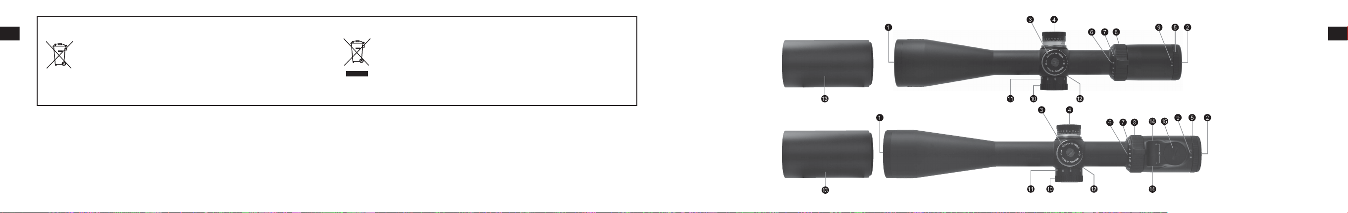
1. Nomenclature
SF MODELS
• 2.5-10×50 SF
• 3-12×56 SF
• 4-16×50 SF
SF IL/SF IL MODELS
• 3-12×56 SF IL
• 4-16×50 SF IL
Fig. 1-1
Fig. 1-2
1 Objective lens
2 Eyepiece lens
3 Elevation adjustment turret
4 Windage adjustment turret
5 Eyepiece adjustment
6 Power index
7 Power scale
8 Power selector ring
9 Diopter index dot
0 Side focus adjustment turret
a Distance scale
b Distance index
c Sunshade
d Illumination adjustment buttons
e Battery compartment cover
En
7
En
Elevation adjustment Windage adjustment
Supplied
Shipped
attached to
riflescope
Fig. 1-4
Fig. 1-3
8
Shipped attached to
riflescope
Supplied
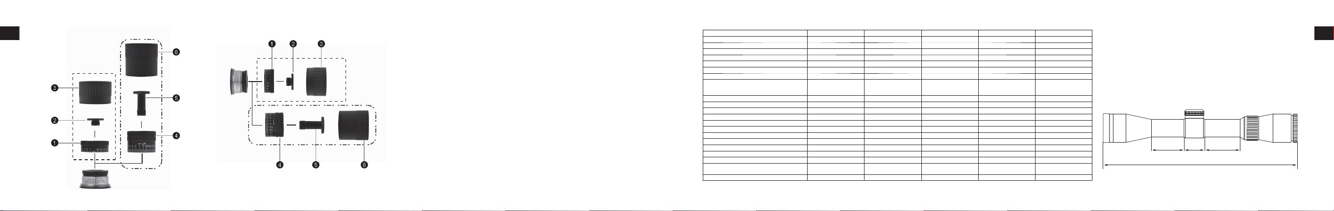
1 Low pro le turret
2 Screw for low pro le turret
3 Cap for low pro le turret
4 High pro le turret
5 Screw for high pro le turret
6 Cap for high pro le turret
2. Specifications
Actual Magnification 2.5-10× 3-12× 3-12× 4-16× 4-16×
Effective objective diameter (mm) 50 56 56 50 50
Exit Pupil * (mm) 5 4.7 4.7 3.1 3.1
Eye Relief ** (in.)/(mm) 3.8-3.7 / 96.5-94.0 3.7-3.7 / 94.0-94.0 3.7-3.7 / 94.0-94.0 3.6-3.6 / 91.4-91.4 3.6-3.6 / 91.4-91.4
Tube Diameter (in.)/(mm) 1.2 / 30 1.2 / 30 1.2 / 30 1.2 / 30 1.2 / 30
Objective outside diameter (in.)/(mm) 2.3 / 57.3 2.5 / 63.3 2.5 / 63.3 2.3 / 57.3 2.3 / 57.3
Eyepiece outside diameter (in.)/(mm) 1.7 / 44 1.7 / 44 1.7 / 44 1.7 / 44 1.7 / 44
Adjustment Graduation 1 click: 1/4 in. @ 100 yd.
Max. internal adjustment ***(MOA)
Parallax Setting (yd.)/(m) 50-∞ / 45.72-∞ 50-∞ / 45.72-∞ 50-∞ / 45.72-∞ 50-∞ / 45.72-∞ 50-∞ / 45.72-∞
Field of view at 100yd. ** (ft) 47.4-11.8 39.4-9.8 39.4-9.8 29.6-7.4 29.6-7.4
Field of view at 100m ** (m) 15.8-3.9 13.1-3.3 13.1-3.3 9.9-2.5 9.9-2.5
Length (a) (in.)/(mm) 13.7 / 349 14.3 / 364 14.3 / 364 14.8 / 375 14.8 / 375
Mount length (b) (in.)/(mm) 2.1 / 54 2.1 / 54 2.1 / 54 2.7 / 68 2.7 / 68
Mount length (c) (in.)/(mm) 1.5 / 38 1.5 / 38 1.5 / 38 1.5 / 38 1.5 / 38
Mount length (d) (in.)/(mm) 1.9 / 47 1.9 / 47 1.9 / 47 1.9 / 47 1.9 / 47
Weight (oz)/(g) 23.6 / 670 23.8 / 675 25.8 / 730 22.9 / 650 24.9 / 705
Power Source – – 3-Volts Lithium CR2032 – 3-Volts Lithium CR2032
Reticle Intensity Adjustment – – 33 position (OFF to 32) – 33 position (OFF to 32)
EMC
Environment – – RoHS, WEEE – RoHS, WEEE
* at maximum magnification ** (at minimum magnification)-(at maximum magnification) *** MOA = Minute of Angle
Model 2.5-10×50 SF 3-12×56 SF 3-12×56 SF IL 4-16×50 SF 4-16×50 SF IL
1 click: 7 mm @ 100 m
1 click:1/4 MOA
92
––
1 click: 1/4 in. @ 100 yd.
1 click: 7 mm @ 100 m
1 click:1/4 MOA
78
1 click: 1/4 in. @ 100 yd.
1 click: 7 mm @ 100 m
1 click:1/4 MOA
78 58 58
FCC Part 15 Subpart B Class B,
EU:EMC directive, AS/NZS
1 click: 1/4 in. @ 100 yd.
1 click: 7 mm @ 100 m
1 click:1/4 MOA
–
1 click: 1/4 in. @ 100 yd.
1 click: 7 mm @ 100 m
1 click:1/4 MOA
FCC Part 15 Subpart B Class B,
EU:EMC directive, AS/NZS
En
Objective Eyepiece
bcd
a
Letters a to d in the diagram above refer to lengths (a) to (d) shown in the Specifications table.
9

Reticle Subtension Chart
En
Advanced BDC reticle Advanced BDC w/Dot
Letters A to Q in the diagram above refer to the reticle subtensions of units A to Q shown on the table to the right.
10
Model 2.5-10×50 SF 3-12×56 SF 3-12×56 SF IL
Reticle Advanced BDC Advanced BDC Advanced BDC w/Dot
Magnification (×) 2.5 10 3 12 3 12
Unit (in.) (cm) (in.) (cm) (in.) (cm) (in.) (cm) (in.) (cm) (in.) (cm)
A 1.00 2.78 0.25 0.70 1.00 2.78 0.25 0.70 1.00 2.78 0.25 0.70
B 32.00 88.96 8.00 22.24 32.00 88.96 8.00 22.24 32.00 88.96 8.00 22.24
C 2.00 5.56 0.50 1.39 2.00 5.56 0.50 1.39 2.00 5.56 0.50 1.39
D 4.00 11.12 1.00 2.78 4.00 11.12 1.00 2.78 4.00 11.12 1.00 2.78
E 8.00 22.24 2.00 5.56 8.00 22.24 2.00 5.56 8.00 22.24 2.00 5.56
F 18.00 50.04 4.50 12.51 18.00 50.04 4.50 12.51 18.00 50.04 4.50 12.51
G 28.00 77.84 7.00 19.46 28.00 77.84 7.00 19.46 28.00 77.84 7.00 19.46
H 44.00 122.32 11.00 30.58 44.00 122.32 11.00 30.58 44.00 122.32 11.00 30.58
I 60.00 166.80 15.00 41.70 60.00 166.80 15.00 41.70 60.00 166.80 15.00 41.70
J 4.00 11.12 1.00 2.78 4.00 11.12 1.00 2.78 4.00 11.12 1.00 2.78
K 8.00 22.24 2.00 5.56 8.00 22.24 2.00 5.56 8.00 22.24 2.00 5.56
L 9.00 25.02 2.25 6.26 9.00 25.02 2.25 6.26 9.00 25.02 2.25 6.26
M 14.00 38.92 3.50 9.73 14.00 38.92 3.50 9.73 14.00 38.92 3.50 9.73
Reticle subtensions (cm at 100 metres/inches at 100yards)
N 20.00 55.60 5.00 13.90 20.00 55.60 5.00 13.90 20.00 55.60 5.00 13.90
O 1.00 2.78 0.25 0.70 1.00 2.78 0.25 0.70 1.00 2.78 0.25 0.70
P 4.00 11.12 1.00 2.78 4.00 11.12 1.00 2.78 4.00 11.12 1.00 2.78
Q 2.52 7.01 0.63 1.75
Model 4-16×50 SF 4-16×50 SF IL
Reticle Advanced BDC Advanced BDC w/Dot
Magnification (×) 4 16 4 16
Unit (in.) (cm) (in.) (cm) (in.) (cm) (in.) (cm)
A 1.00 2.78 0.25 0.70 1.00 2.78 0.25 0.70
B 32.00 88.96 8.00 22.24 32.00 88.96 8.00 22.24
C 2.00 5.56 0.50 1.39 2.00 5.56 0.50 1.39
D 4.00 11.12 1.00 2.78 4.00 11.12 1.00 2.78
E 8.00 22.24 2.00 5.56 8.00 22.24 2.00 5.56
F 18.00 50.04 4.50 12.51 18.00 50.04 4.50 12.51
G 28.00 77.84 7.00 19.46 28.00 77.84 7.00 19.46
H 44.00 122.32 11.00 30.58 44.00 122.32 11.00 30.58
I 60.00 166.80 15.00 41.70 60.00 166.80 15.00 41.70
J 4.00 11.12 1.00 2.78 4.00 11.12 1.00 2.78
K 8.00 22.24 2.00 5.56 8.00 22.24 2.00 5.56
L 9.00 25.02 2.25 6.26 9.00 25.02 2.25 6.26
M 14.00 38.92 3.50 9.73 14.00 38.92 3.50 9.73
Reticle subtensions (cm at 100 metres/inches at 100yards)
N 20.00 55.60 5.00 13.90 20.00 55.60 5.00 13.90
O 1.00 2.78 0.25 0.70 1.00 2.78 0.25 0.70
P 4.00 11.12 1.00 2.78 4.00 11.12 1.00 2.78
Q 1.88 5.23 0.47 1.31
En
11

En
3. Instructions
(1) Focusing
1 Look through the eyepiece with your eye positioned about 4 in. (10 cm) away from the eyepiece to see either the Advanced BDC
reticle (Fig. 3-1) , or Advanced BDC w/Dot (Fig. 3-2). Be sure your eye is positioned with proper alignment and with proper eye
relief, otherwise the view will “black out.”
2 Point the objective end of the scope at the sky (do NOT point it at the sun) or at a plain unpatterned wall.
3 Turn the eyepiece adjustment counter-clockwise and then turn it clockwise until the reticle appears sharp.
Advanced BDC reticle
Fig. 3-1
Advanced BDC w/Dot
Fig. 3-2
(2) Magnification
• The MONARCH 7 Riflescope has variable magnification. For details, see “2. Specifications”.
To change powers, rotate the power selector ring until the desired magnification appears adjacent to the power index dot.
(3) Adjustment of the riflescope
Sighting through the riflescope, align the rifle with your aiming point on the target and shoot a trial round. If the bullet does not hit the aiming point, adjust the elevation and windage as follows:
• If the bullet hits under the aiming point, turn the elevation adjustment turret (counter-clockwise) in the direction of the arrow marked “U” for up. If the bullet hits high, turn the elevation adjustment turret (clock-
wise) in the direction of the arrow marked “D” for down.
• If the bullet hits to the right of the aiming point, turn the windage adjustment turret (clockwise) in the direction of the arrow marked “L” for left. If the bullet hits to the left of the aiming point, turn the windage
adjustment turret (counter-clockwise) in the direction of the arrow marked “R” for right.
• For the high profile turret, adjustment is made by turning the turret by hand. If the bullet hits under the aiming point, turn the turret in the direction of the arrow marked “U”. If the bullet hits to the left of the aim-
ing point, turn the turret in the direction of the arrow marked “R”.
• After the reticle has been adjusted to the point of impact, replace the turret cap for both the windage and elevation adjustment turrets.
En
12
13
(4) Zero setting of adjustment turret
En
After the reticle has been adjusted to match the point of impact, pull up the adjustment turret to disengage.
The adjustment turret can now be turned freely. Align the zero number to the index line, and then push the
turret back in to set the current position to zero. Screw the turret cap onto the adjustment turret.
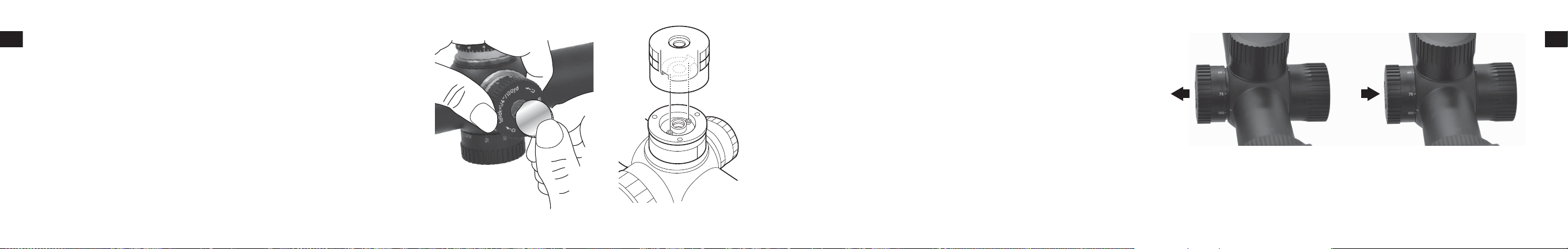
(5) Changing the turret
With the turret held with your fingers to avoid shifting of the aligned scale ring, turn the screw in the top of
the turret counter-clockwise with a coin until the screw comes out (Fig. 3-3). Remove the turret.
Place the turret in position, so that the turret groove is aligned properly (Fig. 3-4).
Be sure to check that the turret has fallen into the correct position and then securely tighten the screw.
If the turret is not properly positioned, it may come off unexpectedly, or spin idly without engaging when
turned. In some cases, the turret cap may cause unintended changes to the turret settings, if the turret is not
properly positioned.
After securely attaching the turret, perform the procedure in (4) Zero setting of adjustment turret.
14
Fig. 3-3 Fig. 3-4
(6) Adjustable side focus
The MONARCH 7 Riflescopes can be more precisely focused within the range of at least 50 yd.
(45.72 m) to infinity by rotating the side focus adjustment.
Parallax can be eliminated and sight alignment will be accurate.
Use its distance scale as a reference guide.
The adjusting ring has a lock system, so that it will not move during shooting.
When adjusting the focus, pull out the adjusting ring. To lock it, push in the adjusting ring (Fig. 3-5).
FREE
Note:
• The windage and elevation scales of MONARCH 7 Riflescopes are calibrated in divisions of 1/4 minute
LOCK
Fig. 3-5
of angle with a click at intervals of 1/4 minute of angle (1 division).
• When adjusting the reticle to the point of aim, remember that 1 minute of angle equals approximately 1 in. (2.54 cm) at 100 yd. (91.44 m).
Therefore, if the impact point is 2 in. (5.08 cm) low and 1 in. (2.54 cm) right at 100 yd. (91.44 m) parallax setting, you should adjust 2 minutes of angle up and 1 minute of angle left.
In the case of 50 yd. (45.72 m) parallax setting, the adjusting value is 2×. In the case of 75 yd. (68.58 m) parallax setting, the adjusting value is 1.5×
En
15
 Loading...