

Page 1
M
サービス
計画課
VBA28001-R.3813.A
作成承認印 配布許可印
VBA28001
REPAIR MANUAL
User ID:INC
Printed in Japan March 2010
Copyright © 2010 by Nikon Corporation.
All Rights Reserved.
無断転載を禁ず
!!
Page 2

VBA28001-R.3813.A
Contents
Disassembly.........................................................................................................................D1
Warning........................................................................................................................................................D1
1..External.Appearance..................................................................................................................D2
Rear.cover.unit.............................................................................................................................................D2
Front.cover.unit............................................................................................................................................D6
Discharge.of.main.condenser.......................................................................................................................D7
Top.cover.unit..............................................................................................................................................D8
2..Rear.Cover..................................................................................................................................D9
SD.cover.unit...............................................................................................................................................D9
LCD.monitor.cover....................................................................................................................................D10
Eyepiece.....................................................................................................................................................D10
Retainer.plate.............................................................................................................................................D11
Speaker.......................................................................................................................................................D12
Rear.FPC....................................................................................................................................................D12
LCD.monitor..............................................................................................................................................D13
Rear.button.................................................................................................................................................D13
LV.lever......................................................................................................................................................D14
TFT.sponge................................................................................................................................................D14
SD.access.lamp.window............................................................................................................................D14
3..Top.Cover..................................................................................................................................D15
SB.release.PCB.unit...................................................................................................................................D15
SB.upper.cover...........................................................................................................................................D17
SB.lower.cover.unit...................................................................................................................................D17
AF.assist.lamp.unit....................................................................................................................................D19
Top.cover.FPC.unit....................................................................................................................................D20
Command.dial.unit.....................................................................................................................................D21
Info.&."+.-".aperture.button.......................................................................................................................D21
ON-OFF.dial..............................................................................................................................................D22
Mode.dial.unit............................................................................................................................................D23
Hot.shoe.....................................................................................................................................................D24
Prism.box.unit............................................................................................................................................D25
User ID:INC
Screen.........................................................................................................................................................D26
SI.(super.impose).display.plate..................................................................................................................D26
LCD.unit....................................................................................................................................................D27
G7.lens.unit................................................................................................................................................D27
4..Sub-frame.(tentative)...............................................................................................................D29
Main.condenser..........................................................................................................................................D29
IF.holder.....................................................................................................................................................D29
TOGO.PCB.unit.........................................................................................................................................D30
Battery.box.unit.........................................................................................................................................D31
- D3100 -
Page 3

VBA28001-R.3813.A
Shield.plate.unit.........................................................................................................................................D35
SZ-DC/DC.PCB.unit.................................................................................................................................D36
Sub-frame...................................................................................................................................................D37
Bottom.plate.unit.......................................................................................................................................D38
5..Front.Body.................................................................................................................................D41
Image.sensor.unit.......................................................................................................................................D41
Shutter.PCB...............................................................................................................................................D42
MG.PCB.unit.............................................................................................................................................D47
SQ.PCB.unit...............................................................................................................................................D48
Bayonet.mount...........................................................................................................................................D49
-min.SW...................................................................................................................................................D51
F
Lens.contact.unit........................................................................................................................................D51
AF.sensor.unit............................................................................................................................................D53
Lens.release.button.unit.............................................................................................................................D53
Mirror.unit..................................................................................................................................................D54
Assembly..............................................................................................................................A1
1..Front.Body...................................................................................................................................A1
Mirror.unit....................................................................................................................................................A1
Lens.release.button.unit...............................................................................................................................A2
AF.sensor.unit..............................................................................................................................................A2
Lens.contact.unit..........................................................................................................................................A3
F-min.SW.....................................................................................................................................................A5
Bayonet.mount.............................................................................................................................................A5
SQ.PCB.unit.................................................................................................................................................A7
Height.adjustment.of.aperture.lever.............................................................................................................A8
MG.PCB.unit...............................................................................................................................................A8
Shutter.PCB...............................................................................................................................................A10
Adjustment.of.shutter.curtain.speed..........................................................................................................A14
Inspection and adjustment of ange-back (body-back).............................................................................A15
Image.sensor.unit.......................................................................................................................................A16
2..Sub-frame..................................................................................................................................A18
Bottom.plate.unit.......................................................................................................................................A18
User ID:INC
Radiating.sheet.for.repair...........................................................................................................................A21
Sub-frame...................................................................................................................................................A22
SZ-DC/DC.PCB.unit.................................................................................................................................A23
Sub-frame.unit...........................................................................................................................................A24
Battery.box.unit.........................................................................................................................................A26
TOGO.PCB.unit.........................................................................................................................................A30
G7.lens.unit................................................................................................................................................A31
LCD.unit....................................................................................................................................................A33
SI.(super.impose).display.plate..................................................................................................................A34
- D3100 -
Page 4

VBA28001-R.3813.A
Screen.........................................................................................................................................................A34
Prism.box.unit............................................................................................................................................A35
Angle.adjustment.of.main.mirror.and.sub-mirror......................................................................................A35
Inspection and adjustment of "∞ (innity)" focus....................................................................................A36
IF.holder.....................................................................................................................................................A36
Main.condenser..........................................................................................................................................A37
Inspection.for.AE-CCD.positioning..........................................................................................................A38
3..Top.Cover..................................................................................................................................A40
Hot.shoe.....................................................................................................................................................A40
Mode.dial.unit............................................................................................................................................A40
ON-OFF.dial..............................................................................................................................................A42
Info.&."
Command.dial.unit.....................................................................................................................................A43
Top.cover.FPC.unit....................................................................................................................................A44
AF.assist.lamp.unit....................................................................................................................................A45
SB.lower.cover.unit...................................................................................................................................A45
SB.upper.cover...........................................................................................................................................A47
SB.release.PCB.unit...................................................................................................................................A48
"..aperture.button.....................................................................................................................A42
+ -
4..Rear.Cover................................................................................................................................A51
SD.access.lamp.window............................................................................................................................A51
TFT.sponge................................................................................................................................................A51
LV.lever......................................................................................................................................................A51
Rear.button.................................................................................................................................................A52
LCD.monitor..............................................................................................................................................A52
Rear.FPC....................................................................................................................................................A53
Speaker.......................................................................................................................................................A53
Eyepiece.....................................................................................................................................................A55
LCD.monitor.cover....................................................................................................................................A55
User ID:INC
SD.cover....................................................................................................................................................A56
5..External.Appearance................................................................................................................A57
Top.cover.unit............................................................................................................................................A57
Adjustment.of.camera.body.(except.imaging)...........................................................................................A59
Firmware.update........................................................................................................................................A61
How.to.connect.camera.and.PC.................................................................................................................A61
How.to.install.inspection.and.adjustment.software.for.camera.body.(except.imaging)............................A61
Inspection.and.adjustment.for.AE.accuracy...............................................................................................A61
Inspection.and.adjustment.for.AF.accuracy...............................................................................................A62
Conrmation of data..................................................................................................................................A63
Switch.information.monitor.......................................................................................................................A63
Inspection.of.sequence.operation...............................................................................................................A63
Inspection.of.sequence.error......................................................................................................................A63
- D3100 -
Page 5

VBA28001-R.3813.A
CPU.version,.number.of.release.times.......................................................................................................A63
Inspection.of.LCD.light-up........................................................................................................................A63
Reset.of.compensated.AF.defocus.amount................................................................................................A63
Rewriting.of.offset.value.of.AF.adj..lens...................................................................................................A63
Front.cover.unit..........................................................................................................................................A65
Rear.cover.unit...........................................................................................................................................A67
Measurement.of.consumption.current.value..............................................................................................A71
Operation.check.of.image.sensor.cleaning................................................................................................A72
Image.adjustment.1....................................................................................................................................A74
Image.adjustment.2....................................................................................................................................A74
Image.adjustment.3....................................................................................................................................A75
Image.adjustment.4....................................................................................................................................A75
Image.adjustment.5....................................................................................................................................A75
Image.adjustment.6....................................................................................................................................A76
Image.adjustment.7....................................................................................................................................A76
Obtaining.of.reference.value......................................................................................................................A77
Factory.default.setting................................................................................................................................A77
Conrmation of data..................................................................................................................................A77
Version.no../Serial.no.................................................................................................................................A77
Wiring..................................................................................................................................E1
Mounting.Drawing.............................................................................................................E2
FUSE.arrangement.............................................................................................................E3
Inspection.standards..........................................................................................................R1
Tool.list.................................................................................................................................T1
Screw.sheet..........................................................................................................................S1
User ID:INC
- D3100 -
Page 6
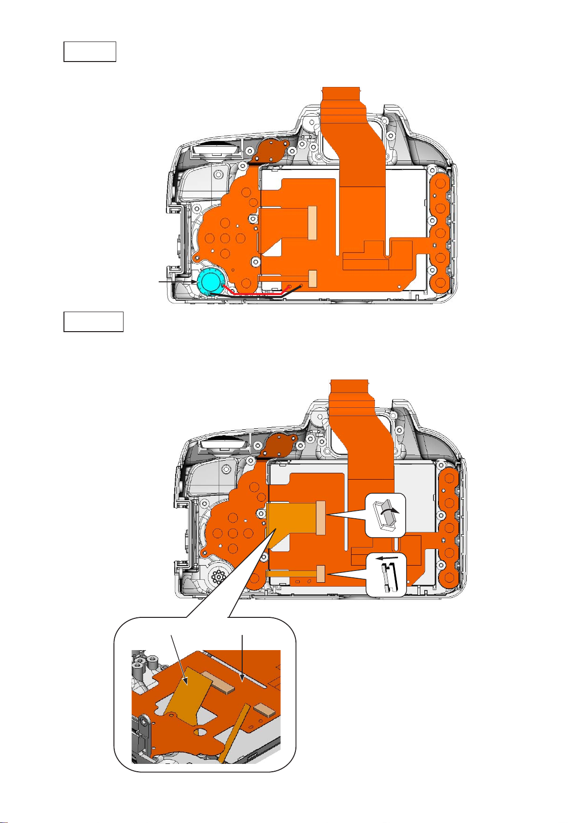
Disassembly
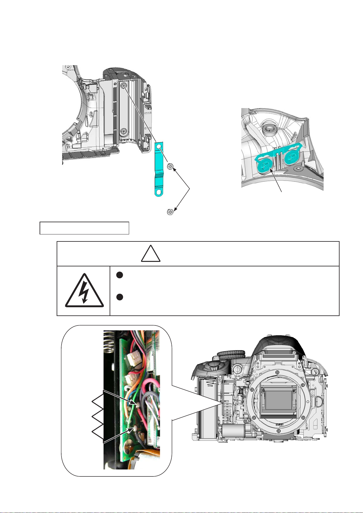
There are high voltage parts inside. Be careful of this electric shock,
when you remove the cover.
You must discharge the main condenser according to the instruction
of this repair manual after you remove the cover.
WARNING!
Warning
Caution:.
..In.disassembly/(re)assembly,.be.sure.to.use.conductive.mat.(J5033).and.wrist.strap.(J5033-5).in.
①
order.to.protect.electric.parts.from.static.electricity.
.Before.disassembling,.be.sure.to.remove.batteries.or.AC.power.cord.
②
VBA28001-R.3813.A
..In.disassembling,.be.sure.to.memorize.the.processing.state.of.wires.and.FPCs,.screws.to.be.
③
xed and their types, etc.
The low-pass lter of the image CCD PCB is easily damaged. Handle it very carefully..
④
ref...In.this.manual,.the.application.of.grease.and.adhesive.is.indicated.by.coloring.
CFD-409Z
(grease:.yellow/adhesive:.red).or.J-number..
Note:.
.The.prism.box.unit.can.be.disassembled.until.the.stage.shown.from.page.D26.to.D28....
①
(ref..parts.list)
.What.are.used.in.this.manual.may.differ.from.the.actual.products.in.forms,.etc.
②
EDB0011
.
Points.to.notice.for.Lead-free.solder.products
Lead-free.solder.is.used.for.this.product.
•
For.soldering.work,.the.special.solder.and.soldering.iron.are.required.
•
Do.not.mix.the.lead-free.solder.with.the.conventional.solder.
•
User ID:INC
Use.the.special.soldering.iron.respectively.for.lead-free.solder.and.lead.solder..They.cannot.
•
be.used.in.common.
- D1 ・ D3100 -
Page 7
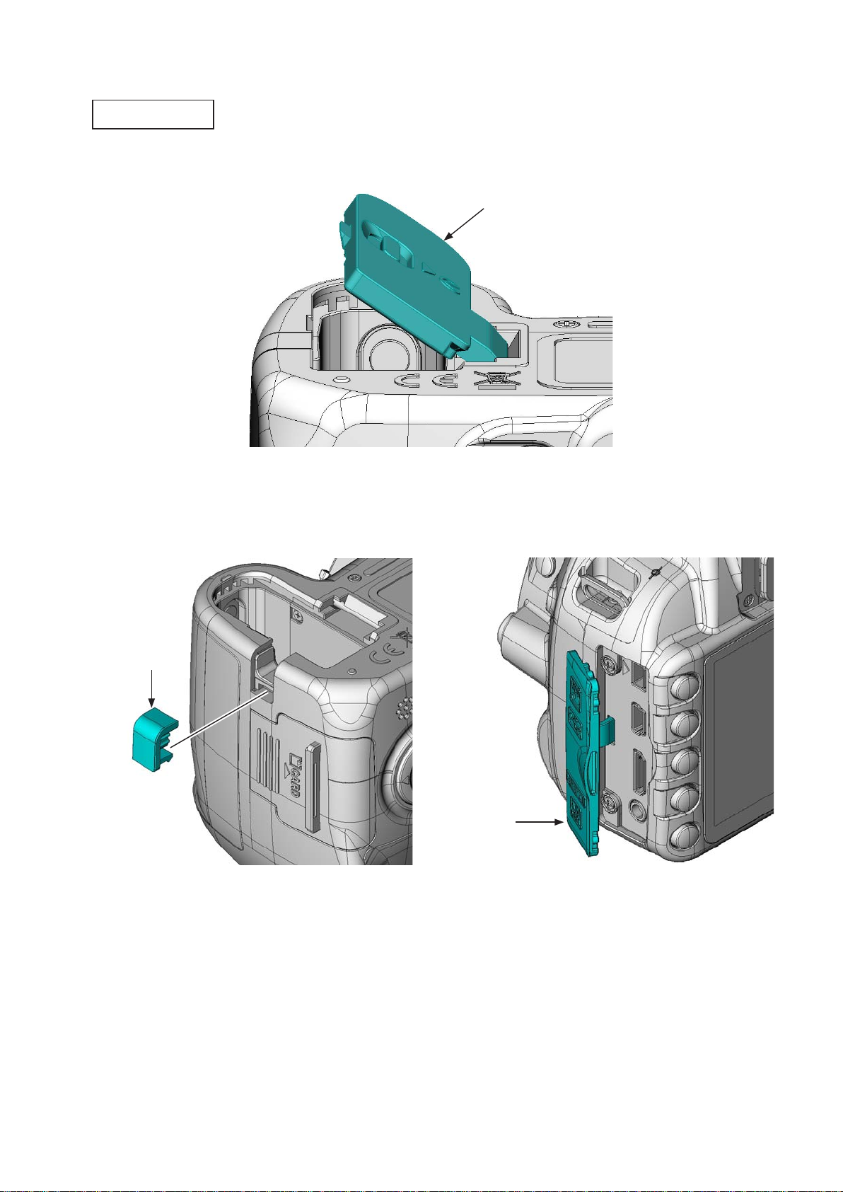
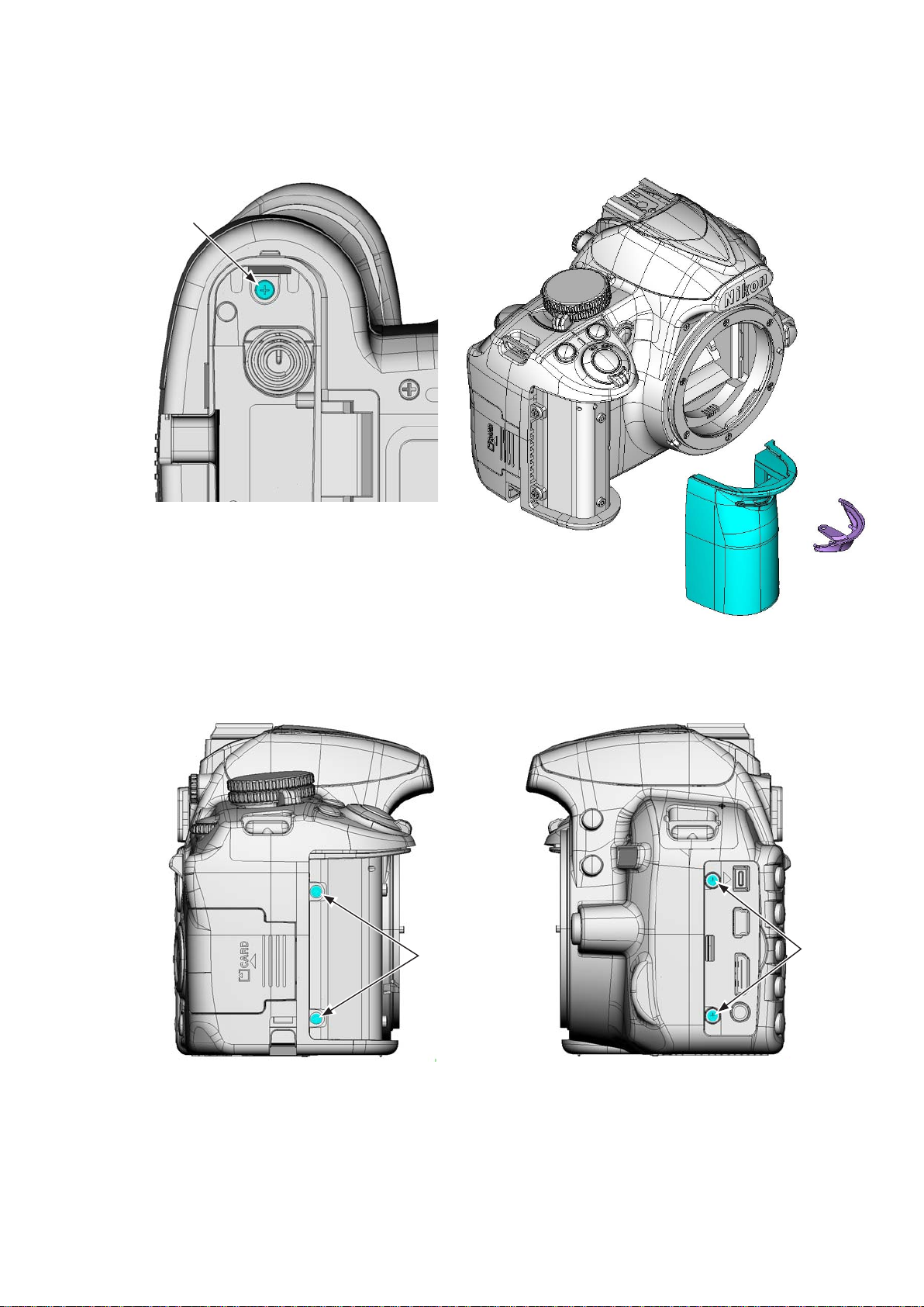
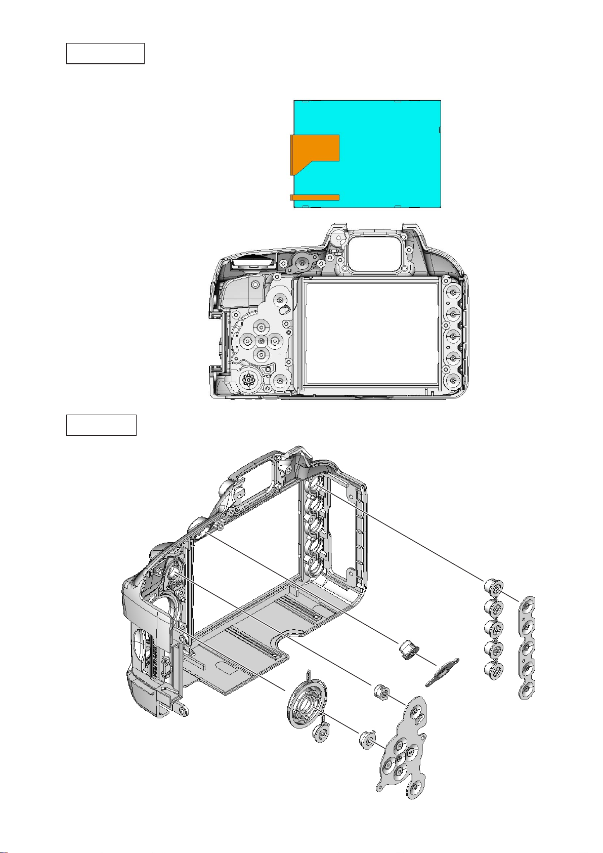
1..External.Appearance
Rear.cover.unit
Incline.the.battery.cover.unit.(#B151).at.an.approx..35°.as.below,.and.remove.it.•
VBA28001-R.3813.A
#B151
Remove.the.power.connector.cover.(#72).
•
Remove.the.IF.cover.(#71).
•
#72
#71
User ID:INC
- D2 ・ D3100 -
Page 8
Remove.the.cover.(#267).
•
Take.out.the.screw.(#614).
•
Take.out.the.two.screws.(#623).
•
Take.out.the.screw.(#634).
•
#267
#634
VBA28001-R.3813.A
#614
#623
Take.out.the.two.screws.(#631).•
#631
User ID:INC
- D3 ・ D3100 -
Page 9
Take.out.the.screw.(#661).
•
Remove.the.grip.unit.(#B26)...(Do.NOT.reuse.the.grip.unit.that.was.once.removed.
•
Remove.the.grip.cover.(#27).
•
#661
VBA28001-R.3813.A
)
Take.out.the.two.screws.(#640).
•
Take.out.the.two.screws.(#623).
•
#640
#27
#B26
#623
User ID:INC
- D4 ・ D3100 -
Page 10
Remove.the.rubber.(#410).and.double-stick.tape.(#411).
•
Take.out.the.screw.(#622).
•
VBA28001-R.3813.A
#410
#411
#622
Lift.up.the.rear.cover.unit.
•
Disconnect.the.FPC.
•
Remove.the.rear.cover.unit.
•
User ID:INC
- D5 ・ D3100 -
Page 11
Front.cover.unit
Take.out.the.two.screws.(#644).and.one.screw.(#639).
•
Take.out.the.three.screws.(#631).
•
Take.out.the.one.screw.(#643).and.two.screws.(#634).
•
#639
#644
VBA28001-R.3813.A
#644
#643
#631
#634
Slacken.the.tripod.base.area,.and.remove.the.front.cover.unit.•
User ID:INC
- D6 ・ D3100 -
Page 12
Take.out.the.two.screws.(#646).from.the.front.cover.(#24).
There are high voltage parts inside. Be careful of this electric shock,
when you remove the cover.
You must discharge the main condenser according to the instruction
of this repair manual after you remove the cover.
WARNING!
•
Remove.the.spring.(#160).
•
Remove.the.button.(#465).
•
#24
#160
#646
VBA28001-R.3813.A
#465
Discharge.of.main.condenser
User ID:INC
2KΩ/5W
- D7 ・ D3100 -
Page 13
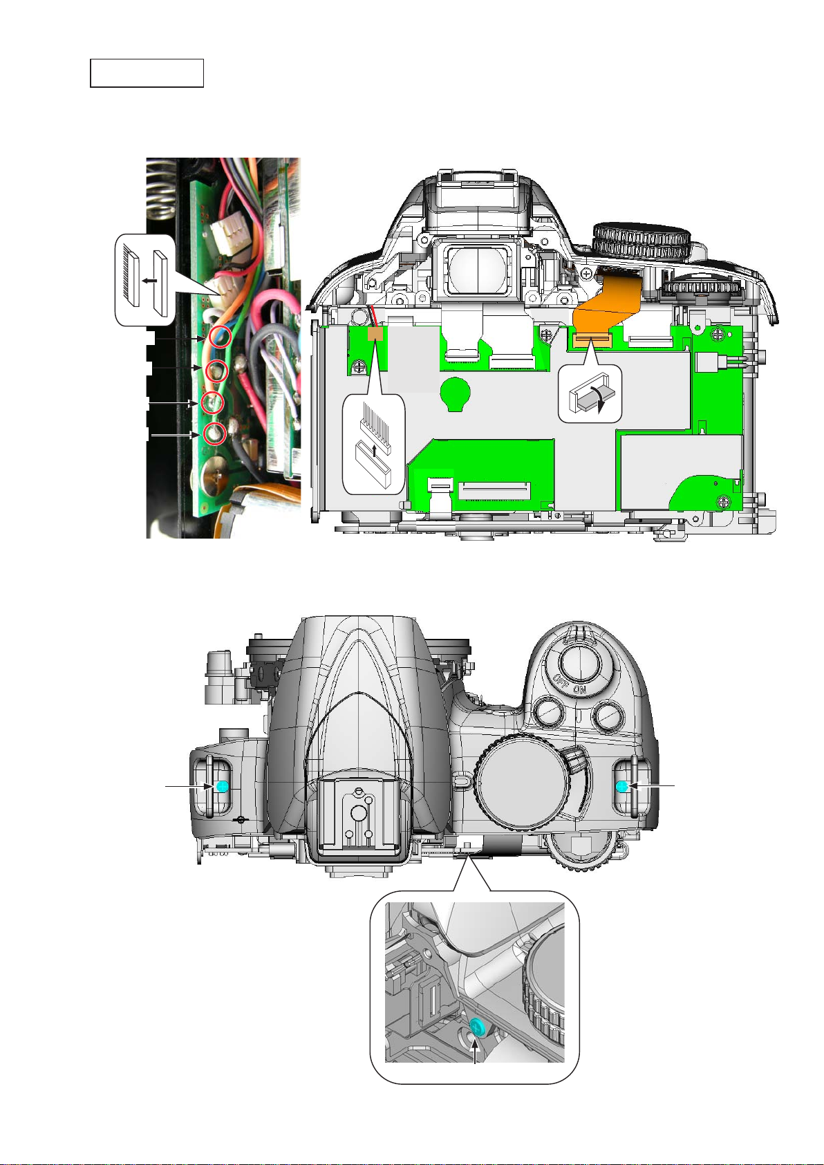
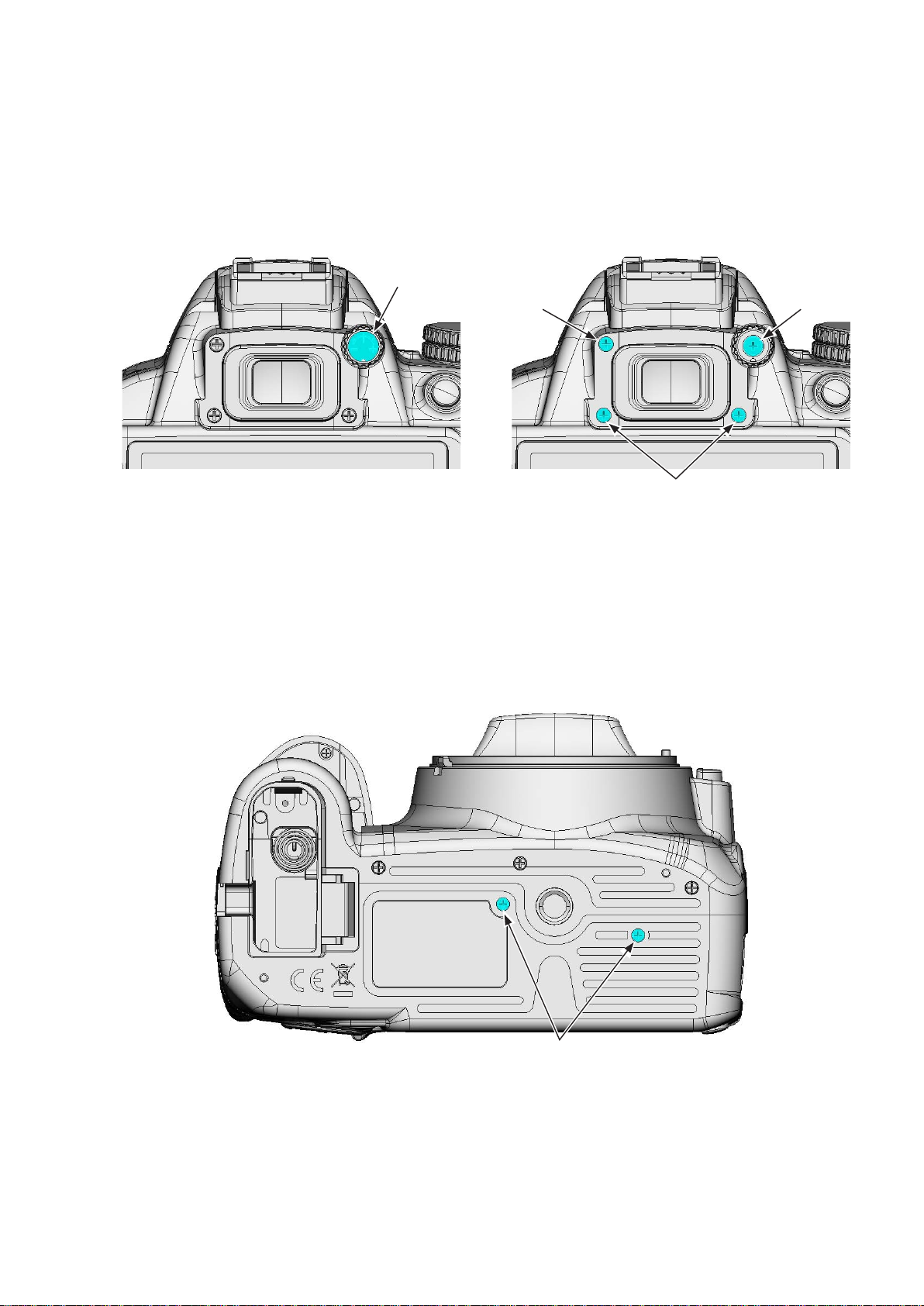
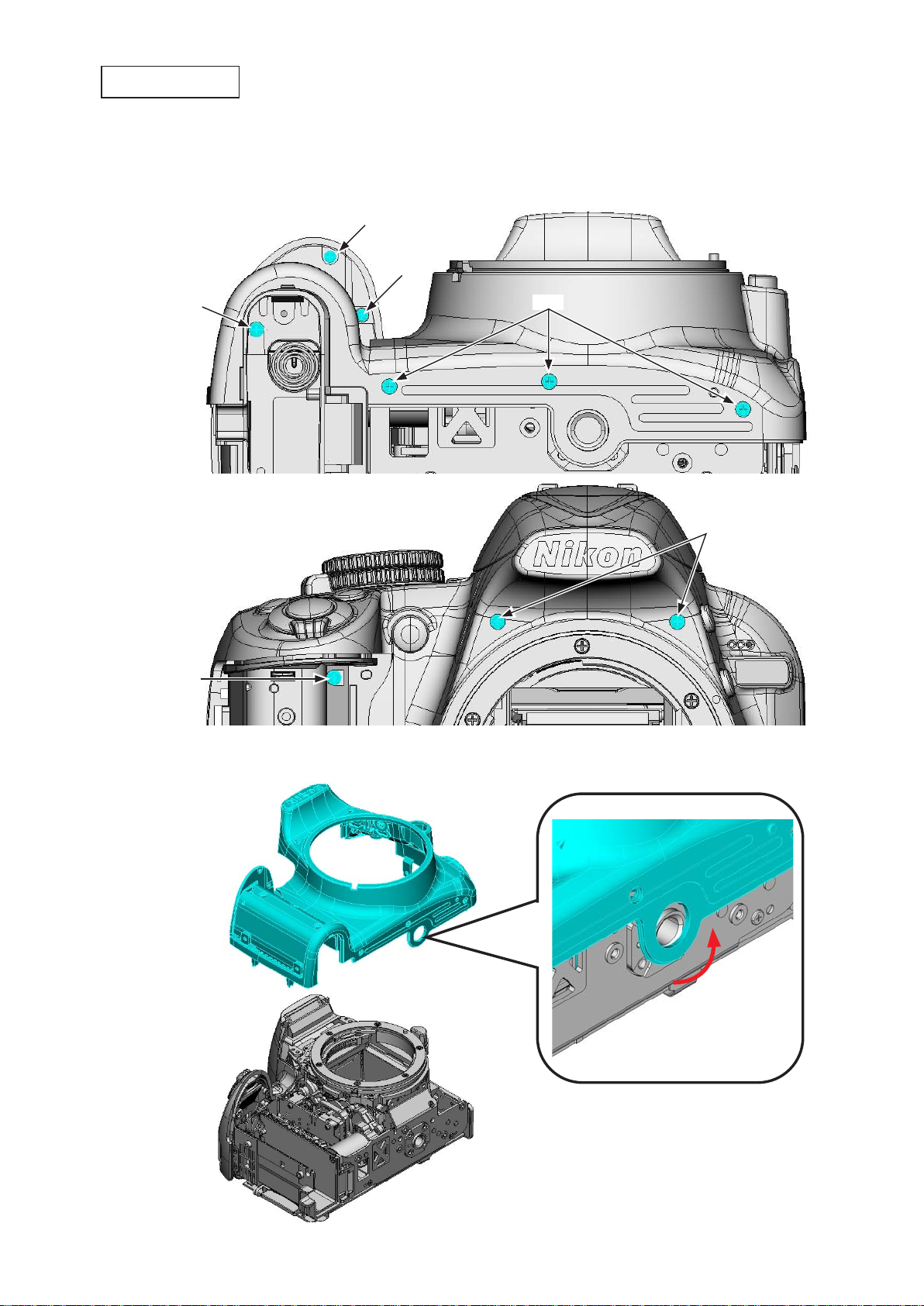
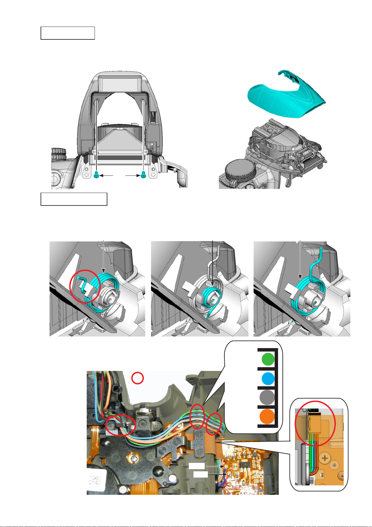
Top.cover.unit
Unsolder.the.four.wires.of.the.SB.lower.cover.unit.
•
Remove.the.harness.and.FPC.
•
[Gray]
[Blue]
[Orange]
[Green]
VBA28001-R.3813.A
Take.out.the.screws.(#631,.#632,.and.#656).
•
Remove.the.top.cover.
•
#631 #632
User ID:INC
#656
- D8 ・ D3100 -
Page 14
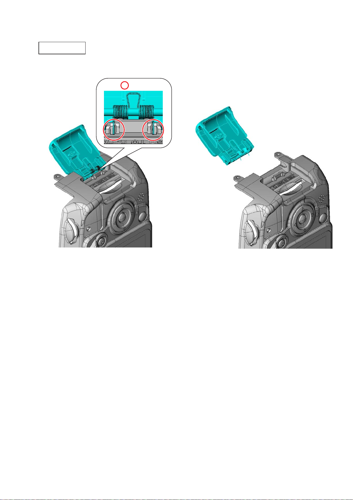
2..Rear.Cover
SD.cover.unit
Remove.the.SD.cover.unit.(#B431).from.the.rear.cover.unit.•
#B431
VBA28001-R.3813.A
Unhook.
User ID:INC
- D9 ・ D3100 -
Page 15
LCD.monitor.cover
Remove.the.LCD.monitor.cover.(#402).
•
Peel.off.the.double-stick.tape.(#403).
•
VBA28001-R.3813.A
#402
#403
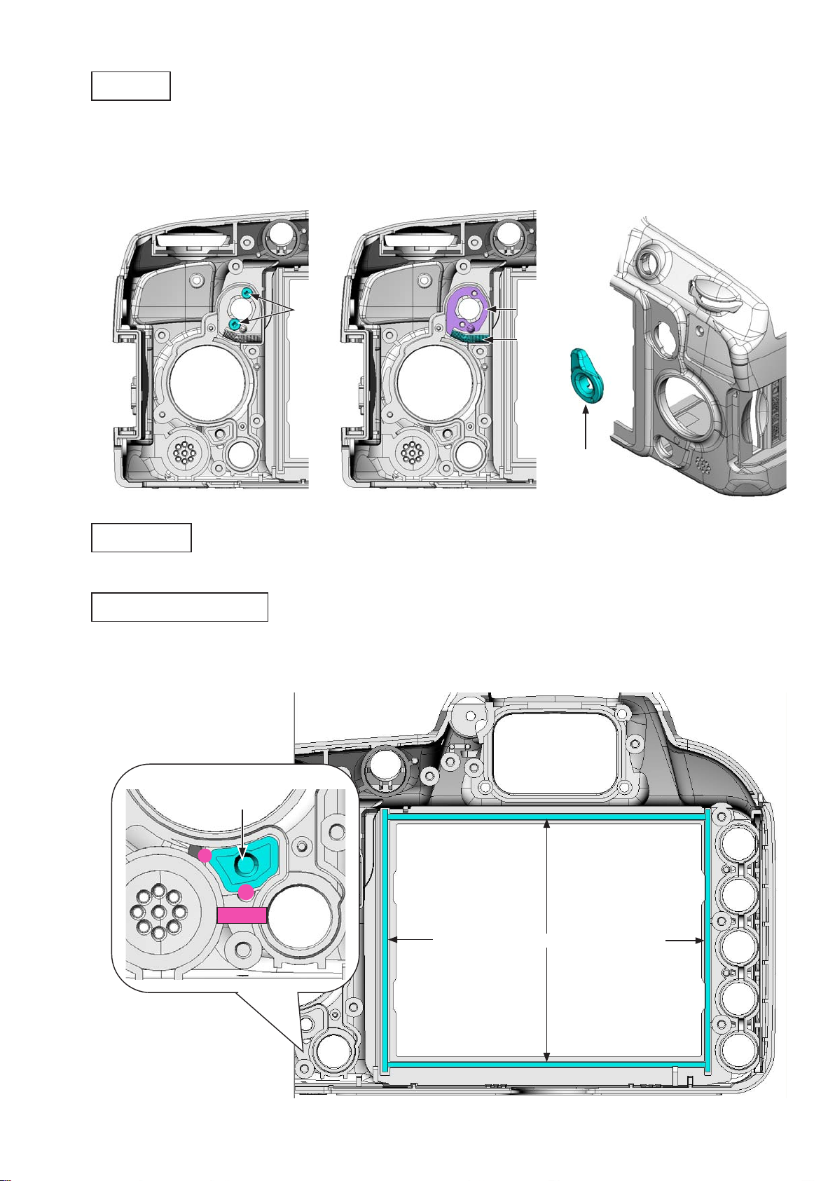
Eyepiece
Take.out.the.two.screws.(#624),.and.remove.the.eyepiece.frame.unit.from.the.rear.cover.
•
Remove.the.sponge.(#476).from.the.eyepiece.frame.(#475).
•
Take.out.the.screw.(#621).
•
Remove.the.retainer.plate.(#266).
•
Remove.the.diopter.adj..knob.(#265).
•
#624
#476
#475
#621
#266
#265
User ID:INC
- D10 ・ D3100 -
Page 16
Retainer.plate
Unsolder.the.two.wires.of.the.speaker.(#1054).•
VBA28001-R.3813.A
Peel.off.the.two.pieces.of.the.tape.[TA-0005.(10×20)].
•
Take.out.the.nine.screws.(#621).
•
Remove.the.retainer.plate.(#406).
•
#621
[Red]
TA-0005.(10x20)x2
[Black]
#621
#621
#406
User ID:INC
- D11 ・ D3100 -
Page 17
Speaker
Remove.the.speaker.(#1054).•
VBA28001-R.3813.A
#1054
Rear.FPC
Disconnect.the.two.FPCs.
•
While.slacking.the.FPC.(see.below).of.the.LCD.monitor.(#1049),.remove.the.rear.FPC.unit.(#B1016).
•
User ID:INC
#1049
#B1016
- D12 ・ D3100 -
Page 18
LCD.monitor
Remove.the.LCD.monitor.(#1049).•
VBA28001-R.3813.A
#1049
Rear.button
#412
#416
#424
#425
#385
#386
User ID:INC
#415
#413
- D13 ・ D3100 -
Page 19
LV.lever
Take.out.the.two.screws.(#619).
•
Remove.the.retainer.plate.(#471),.spring.(#472),.and.LV.lever.(#470).
•
VBA28001-R.3813.A
#619
#471
#472
#470
TFT.sponge
Remove.the.two.sponges.(#404).and.two.sponges.(#405).
•
SD.access.lamp.window
Remove.the.adhesive.(EDC0021),.then.remove.the.SD.access.lamp.window.(#408).
•
User ID:INC
#408
EDC0021
#405
- D14 ・ D3100 -
#404
#405
Page 20
3..Top.Cover
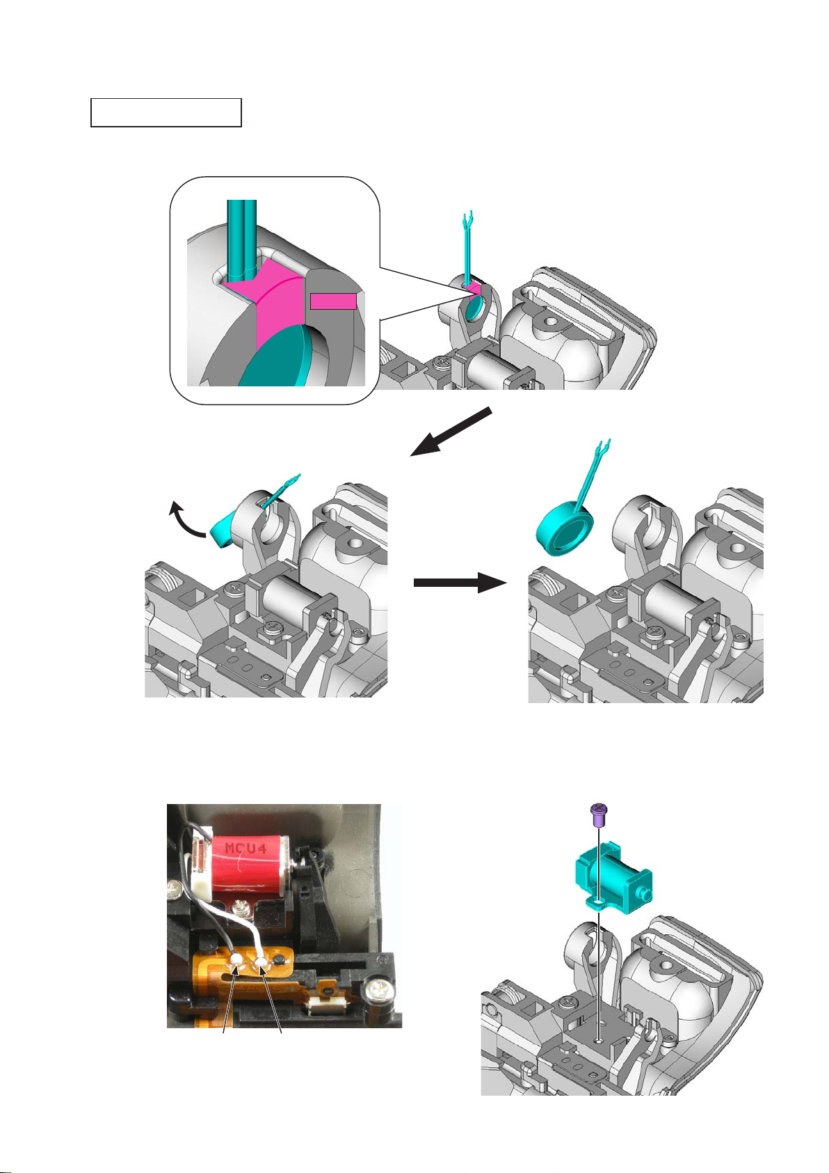
SB.release.PCB.unit
Remove.the."Super.X".(C-8008B),.then.remove.the.microphone.(#1053).•
VBA28001-R.3813.A
C-8008B
Unsolder.the.two.wires.
•
Take.out.the.screw.(#618),.and.remove.the.driving.magnet.(#36).
•
#1053
#618
#36
User ID:INC
[Black] [White]
- D15 ・ D3100 -
Page 21
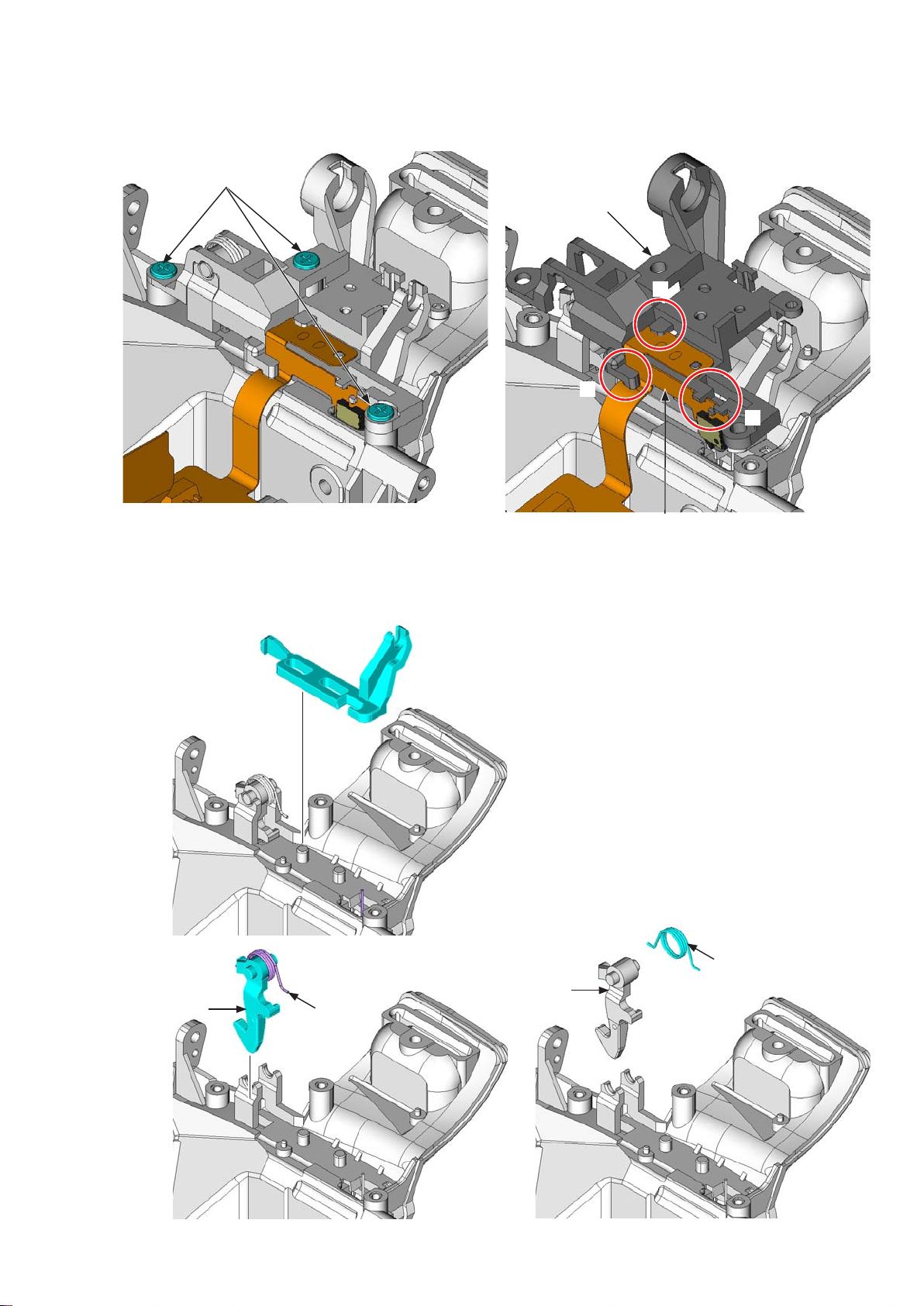
VBA28001-R.3813.A
Take.out.the.three.screws.(#617).
•
Unhook.the.top.cover.FPC.unit.(#B1007).in.the.numeric.order.from.①.to.③,.and.then.remove.the.SB.
•
release.PCB.(#455).
#617
#455
③
②
①
Remove.the.SB.release.lever.(#456).
•
Remove.the.SB.lock.lever.(#309).and.spring.(#458).together.
•
Remove.the.spring.(#458).from.the.SB.lock.lever.(#309).
•
#456
#B1007
#458
User ID:INC
#309
#309
#458
- D16 ・ D3100 -
Page 22
SB upper cover
Take out the two screws (#628).
•
Remove the SB upper cover (#301).
•
#628
SB lower cover unit
VBA28001-R.3813.A
#301
Unhook the spring (#305).
•
Unhook the spring (#459) and spring (#305).
•
#305
Unsolder the two wires.
•
Release the four wires from the four guides.
•
Guide
=
#459
#305
[Green]
[Blue]
[Gray]
User ID:INC
[Orange]
[Blue]
[Red]
- D17 ・ D3100 -
Page 23
VBA28001-R.3813.A
Pull.out.the.wires.•
Remove.the.roller.(#308).while.releasing.the.hooks.•
Release.hooks.
#308
User ID:INC
Remove.the.SB.lower.cover.unit.(#B302).•
#B302
- D18 ・ D3100 -
Page 24
AF.assist.lamp.unit
Unsolder.the.two.wires.of.the.harness.(#1027).•
VBA28001-R.3813.A
#1027
[Red]
[Black]
Unsolder.the.two.wires.of.the.AF.assist.lamp.unit.(#B325).
•
Take.out.the.screw.(#629),.and.remove.the.AF.assist.lamp.unit.(#B325).
•
#629
#B325
[Black]
[Uncoated]
User ID:INC
- D19 ・ D3100 -
Page 25
Top.cover.FPC.unit
Remove the ve solders of the hot shoe.
•
Take.out.the.three.screws.(#617).
•
VBA28001-R.3813.A
#617
Remove.the.top.cover.FPC.unit.(#B1007).•
Caution:.When.the.top.cover.FPC.
unit.is.removed,.be.careful.that.the.
inner.click.spring.(#361).and.click.
ball.(#362).in.the.command.dial.may.
pop.out.
#361#362
Solder×5
#B1007
User ID:INC
#B360
- D20 ・ D3100 -
Page 26
Command.dial.unit
Remove.the.command.dial.unit.(#B360).
•
Remove.the.click.ball.(#362).and.click.spring.(#361).
•
#B360
VBA28001-R.3813.A
#362
#361
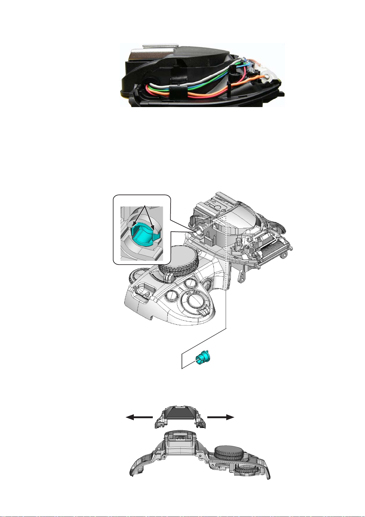
Info.&."+.-".aperture.button
Remove.the.button.(#381).•
#381
User ID:INC
- D21 ・ D3100 -
Page 27
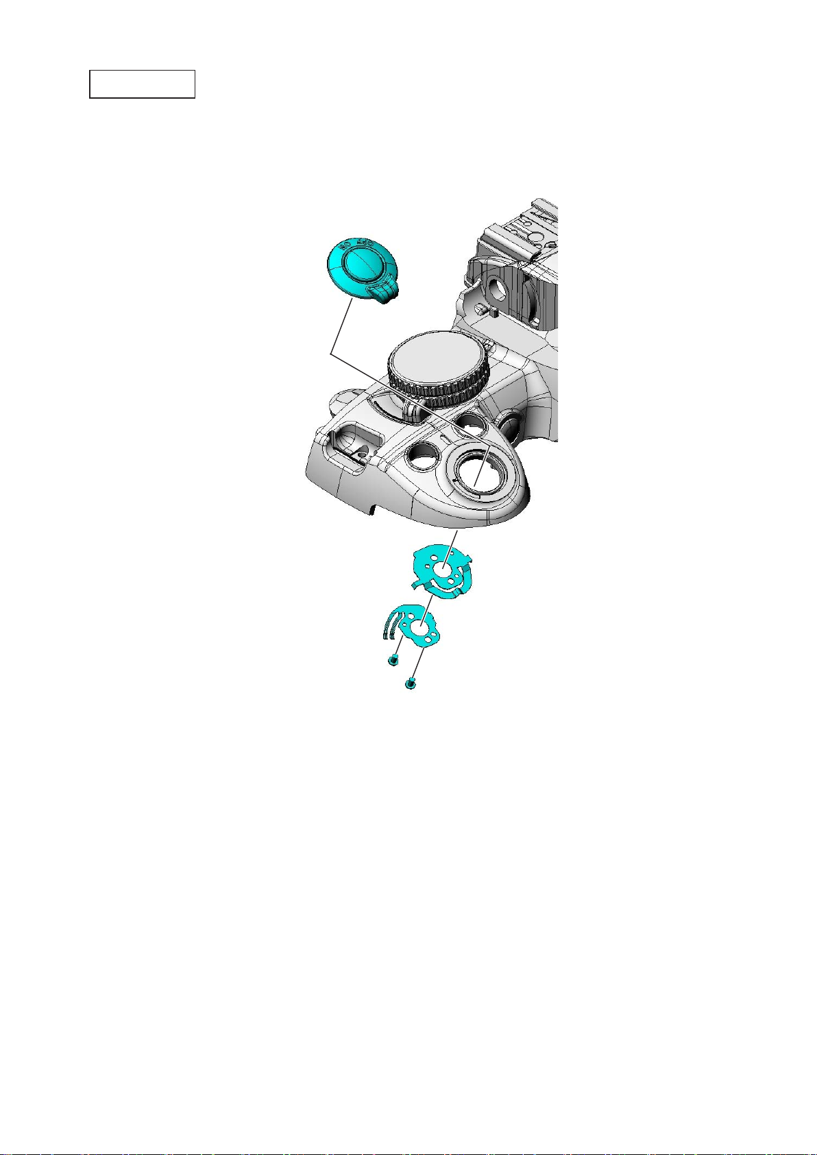
ON-OFF.dial
Take.out.the.two.screws.(#615).
•
Remove.the.ON-OFF.SW.brush.(#348).and.ON-OFF.click.plate.(#347).
•
Remove.the.power.dial.unit.(#B345).
•
#B345
VBA28001-R.3813.A
#615
#347
#348
User ID:INC
- D22 ・ D3100 -
Page 28
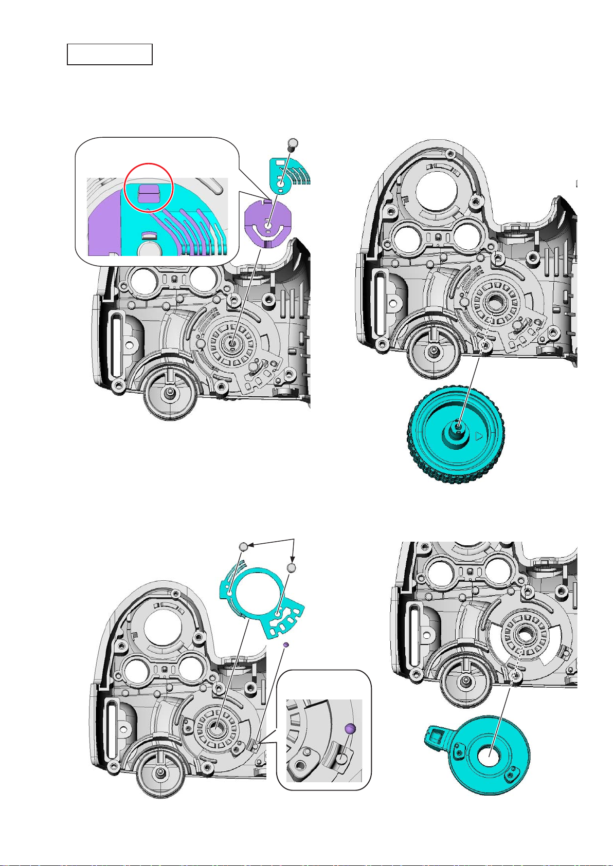
Mode.dial.unit
Take.out.the.screw.(#616).
•
Remove.the.contact.brush.(#372).and.click.spring.(#373).
•
Remove.the.mode.dial.unit.(#B371).
•
VBA28001-R.3813.A
Unhook.
#616
#372
#373
#B371
Take.out.the.two.screws.(#663).
•
Remove.the.contact.brush.(#375),.click.ball.(#362),.and.release.mode.dial.(#374).
•
#663
#375
#362
[#362].close-up
#374
User ID:INC
- D23 ・ D3100 -
Page 29
VBA28001-R.3813.A
Hot.shoe
Take.out.the.four.screws.(#627).
•
Remove.the.holder.plate.(#322),.hot.shoe.spring.(#318),.hot.shoe.(#316),.and.hot.shoe.mold.unit.(#B317).
•
#318
#316
#B317
#322
#627
User ID:INC
- D24 ・ D3100 -
Page 30
VBA28001-R.3813.A
Prism.box.unit
Note:.The.prism.box.unit.can.be.disassembled.until.the.stage.shown.from.page.D26.to.D28,..
Further.disassembly.can.not.be.made...(ref..parts.list)
Disconnect.the.two.FPCs.
•
Take.out.the.two.screws.(#613).
•
#613
Remove.the.prism.box.unit.•
User ID:INC
- D25 ・ D3100 -
Page 31

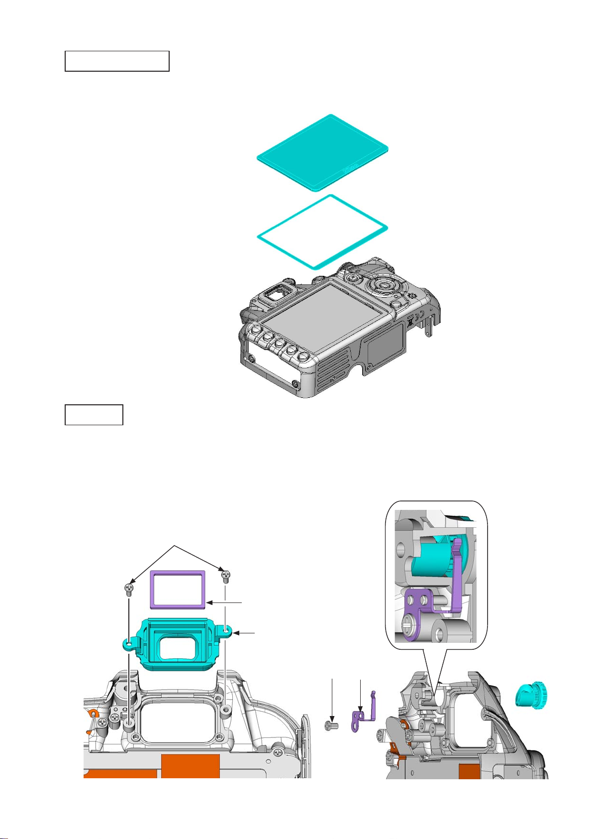
Screen
SI.(super.impose).display.plate
VBA28001-R.3813.A
#284
#282
#297A.or.#297B
#3
Remove.the.rubber.(#281).
•
Remove.the.SI.display.plate.(#13A).
•
Remove.the.rubber.(#285).
•
Caution:..The.SI.display.plate.(#13).tends.to.be.scratched.easily,.so.do.NOT.wipe.it.out.with.
alcohol...If.dust.or.dirt.is.attached,.blow.it.with.a.blower.
#281
User ID:INC
#285
#13A
- D26 ・ D3100 -
Page 32

LCD.unit
Take.out.the.two.screws.(#650).
•
Remove.the.LCD.unit.(#B1045).and.tape.(#291).
•
VBA28001-R.3813.A
#B1045
#291
#650
G7.lens.unit
Disconnect.the.FPC’s.one.end.of.the.AE-CCD,.and.remove.the.other.end.from.the.shading.plate.(#271).
•
Peel.off.the.double-stick.tape.[TA-0026.(4.5×4.5)].
•
①
User ID:INC
②
TA-0026.(4.5×4.5)
#271
- D27 ・ D3100 -
Page 33

VBA28001-R.3813.A
Remove.the.shading.plate.(#271).and.sponge.(#293).•
Unhook.
=
Pull.out.the.pin.(#262).
•
Remove.the.G7.lens.unit.
•
#262
Be.careful.of.popout.of.the.spring.
#271
#293
Pushing.from.the.prism.
side.will.make.it.easier.
to.pull.out.[#262].
Release.from.the.
groove.side.
User ID:INC
#264
#268
#7
- D28 ・ D3100 -
Page 34

4..Sub-frame.(tentative)
Main.condenser
Peel.off.the.tape.[TA-0015.(13×28)].
•
Unsolder.the.two.wires.from.the.main.condenser.(#1043).
•
Remove.the.main.condenser.(#1043).
•
Peel.off.the.double-stick.tape.(#141).
•
TA-0015.(13x28)
VBA28001-R.3813.A
[Black]
[Red]
IF.holder
Take.out.the.screw.(#633).
•
Remove.the.IF.holder.(#70).
•
#70
#1043
#141
User ID:INC
#633
- D29 ・ D3100 -
Page 35

TOGO.PCB.unit
Peel.off.the.tape.[TA-0015.(13×18)].
•
Remove.the.three.FPCs.and.harness.
•
Take.out.the.four.screws.(#656).and.one.screw.(#607).
•
TA-0015.(13×18)
#607
VBA28001-R.3813.A
#656
#656 #656
Remove.the.TOGO.PCB.unit.(#B2001).
•
Disconnect.the.connection-FPC.(#1015).from.the.connectors.in.the.numeric.order.from.①.to.②.
•
Remove.by.sliding.inwards.
②
①
User ID:INC
#1015
#B2001
- D30 ・ D3100 -
Page 36

Battery.box.unit
Remove.the.spring.(#158).•
Take.out.the.one.screw.(#638).and.two.screws.(#643).•
VBA28001-R.3813.A
#158
#638
Disconnect.the.FPC.by.slightly.tilting.the.battery.box.sideways.
•
Unsolder.the.four.wires.of.the.power.drive.PCB.
•
Remove.the.harness.
•
#643
[Red]
User ID:INC
- D31 ・ D3100 -
[Purple].x2
[Black]
Page 37

Unsolder.the.two.wires.of.the.harness.(#1026).•
Unsolder.the.two.wires.of.the.condenser.
•
The.battery.box.unit.will.come.off.
•
[Red]
VBA28001-R.3813.A
[Red]
#1026
[Blue]
[Black]
Take.out.the.two.screws.(#658).and.one.screw.(#664).
•
Remove.the.power.drive.PCB.(#1004).
•
#1004
User ID:INC
#664
#658
- D32 ・ D3100 -
Page 38

Remove.the."O"-ring.(#147).
•
Take.out.the.two.screws.(#651),.and.remove.the.eyelet.(#145).
•
#147
VBA28001-R.3813.A
#145
#651
Peel.off.the.sheet.(#150).•
#150
- D33 ・ D3100 -
User ID:INC
Page 39

VBA28001-R.3813.A
Remove.the.GND.plate.(#159).•
#159
Peel.off.the.sheet.(#154).•
#154
Remove.the.adhesive.(EDC0021),.and.remove.the.pin.(#155).from.the.battery.box.(#156).•
#155
EDC0021
User ID:INC
#156
- D34 ・ D3100 -
Page 40

Shield.plate.unit
Take.out.the.three.screws.(#607).•
Displace.slightly.the.GND.plate.of.the.image.sensor.unit,.and.remove.the.shield.plate.unit.•
VBA28001-R.3813.A
#607
GND.plate
Peel.off.the.tape.(#481).from.the.shield.plate.(#480).•
#480
User ID:INC
#481
- D35 ・ D3100 -
Page 41

VBA28001-R.3813.A
Disconnect.the.FPC.
•
Take.out.the.two.screws.(#635).and.two.screws.(#656).
•
Remove.the.sub-frame.unit...(When.this.is.removed,.be.careful.not.to.get.caught.by.a.wire.of.the.
•
condenser.
Disconnect.the.connection-FPC.(#1020).
•
)
#635
#1020
Be.careful.not.to.get.
caught.by.a.wire.of.
the.condenser.
#656
SZ-DC/DC.PCB.unit
Take.out.the.two.screws.(#656).
•
Remove.the.SZ-DC/DC.PCB.unit.(#B1002).
•
Remove.the.four.wires.
•
#656
User ID:INC
#B1002
- D36 ・ D3100 -
[Red]
[Black]
[Purple].x2
Page 42

Sub-frame
Remove.the."O"-ring.(#147).
•
Take.out.the.two.screws.(#657),.and.remove.the.eyelet.(#145).
•
#147
VBA28001-R.3813.A
#657
#145
Remove.the.two.rubbers.(#63).from.the.sub-frame.(#62).
•
Peel.off.the.tape.[TA-0016.(5×8)].
•
#63
#62
TA-0016.(5×8)
#63
User ID:INC
- D37 ・ D3100 -
Page 43

Bottom.plate.unit
Peel.off.the.shield.sheet.(#65).from.the.front.body.unit.•
VBA28001-R.3813.A
#65
Peel.off.the.heat-radiating.sheet.of.the.image.sensor.unit.(#B3051).from.the.bottom.plate.unit.
•
Take.out.the.two.screws.(#647),.and.remove.the.bottom.plate.unit.
•
#647
① ②
User ID:INC
Heat-radiating.sheet
- D38 ・ D3100 -
Page 44

Remove.the.two.wires.of.the.condenser.
•
Peel.off.the.tape.[TA-0026.(5×40)].
•
[Black]
VBA28001-R.3813.A
[Red]
TA-0026(5×40)
User ID:INC
- D39 ・ D3100 -
Page 45

VBA28001-R.3813.A
Attach.the.shield.sheet.(#65).to.the.bottom.plate.unit.•
Attach by tting in each round hole.
#65
Take.out.the.four.screws.(#630),.and.remove.the.tripod.base.(#68).from.the.bottom.plate.(#61).•
#630
#68
#61
User ID:INC
- D40 ・ D3100 -
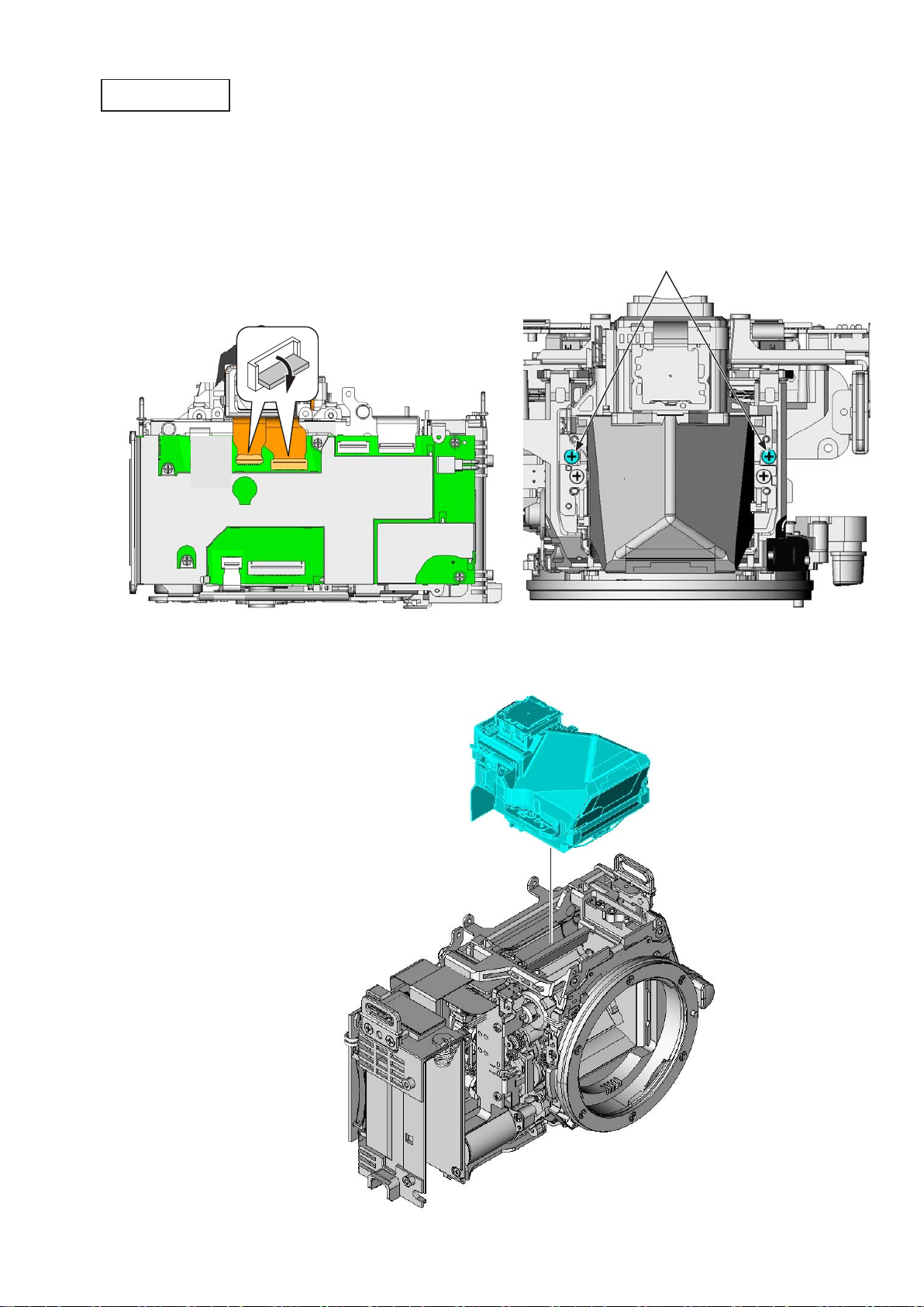
Page 46

5..Front.Body
Image.sensor.unit
Peel.off.the.tape.(#59).
•
Take.out.the.three.screws.(#634),.and.remove.the.three.washers.(#80).
•
Remove.the.image.sensor.unit.(#B3051).
•
Remove.the.washers.(#87-#107).
•
#59
VBA28001-R.3813.A
#634×3
#80×3
#B3051
#87.~.#107×3
User ID:INC
- D41 ・ D3100 -
Page 47

Peel.off.the.tape.[TA-0016.(5×8)].from.the.lens.contact.unit.(#B2113).
•
Unsolder.the.three.wires.of.the.harness.(#1028).
•
TA-0016.(5×8)
VBA28001-R.3813.A
[Red]
[Gray]
#1028
[Black]
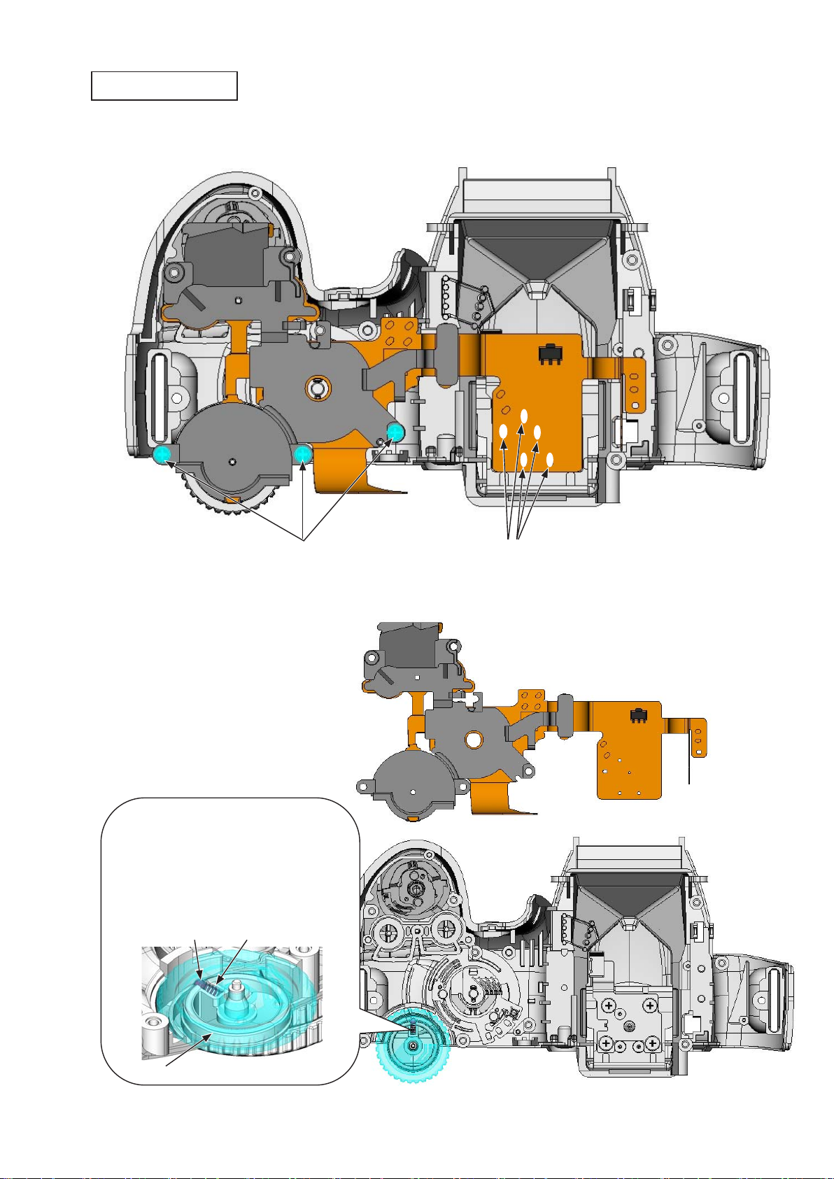
Shutter.PCB
Turn.the.gear.(indicated.in.red).of.the.SQ.PCB.unit.in.the.direction.of.the.arrow.to.raise.the.mirror...
•
Then,.set.the.lever's.position.of.the.MG.PCB.unit.to.the."OK".position.as.below.
Caution:.It.may.require.turning.the.gear.several.times.to.become.at."OK".position.
User ID:INC
OK NG:.Not.Good NG:.Not.Good
- D42 ・ D3100 -
Page 48

Take.out.the.screw.(#612).
•
Remove.the.retainer.plate.(#2004).
•
Take.out.the.two.screws.(#612).
•
Remove.the.brake.plate.(#196).
•
VBA28001-R.3813.A
#2004
#612
#612
Take.out.the.screw.(#604).
•
Remove.the.retainer.plate.(#2003).
•
#196
#604
#2003
User ID:INC
- D43 ・ D3100 -
Page 49

VBA28001-R.3813.A
Take.out.the.screw.(#608).
•
Remove.the.holder.plate.(#2002).
•
Caution:.Be.careful.that.the.spring.may.pop.out...To.avoid.deformation.of.[#2002],.do.NOT.hold.
the.other.areas.than.indicated.in.red.
Unhook.the.springs.(#178.and.#179).
•
#608
#2002
#179
Unhook.
=
#178
User ID:INC
- D44 ・ D3100 -
Page 50

VBA28001-R.3813.A
Remove.the.shutter.curtain.unit.(#B2016),.and.also.remove.the.spring.(#178).•
#B2016
#178
Remove.the.retainer.plate.(#2015).•
#2015
User ID:INC
- D45 ・ D3100 -
Page 51

Remove.the.shutter.curtain.unit.(#B2016),.and.also.remove.the.spring.(#179).•
VBA28001-R.3813.A
#B2016
#179
Take.out.the.screw.(#619).
•
Remove.the.shutter.PCB.unit.(#2001RP).
•
Caution:.To.avoid.deformation.of.[#2001RP],.do.NOT.hold.the.other.areas.than.indicated.in.red.
#619
#2001RP
User ID:INC
- D46 ・ D3100 -
Page 52

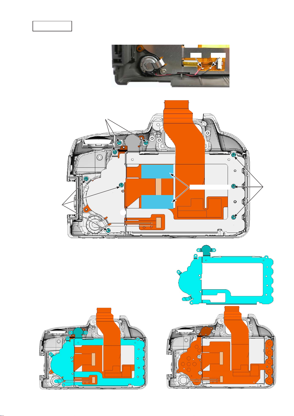
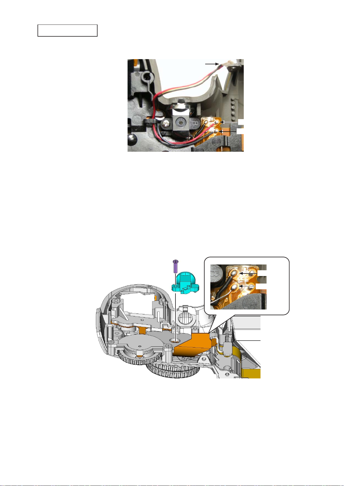
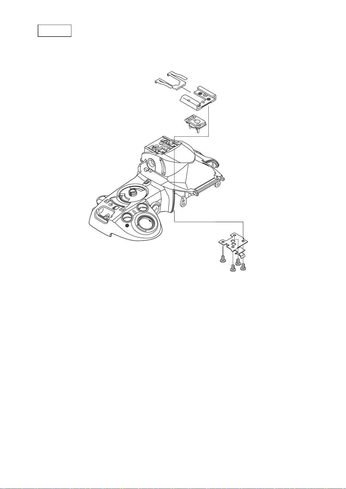
MG.PCB.unit
Unsolder.the.four.wires.
•
Take.out.the.two.screws.(#607).
•
Remove.the.MG.PCB.unit.(#B176).
•
VBA28001-R.3813.A
[Black]
[Red]
#607
#B176
User ID:INC
- D47 ・ D3100 -
Page 53

VBA28001-R.3813.A
SQ.PCB.unit
Turn.the.gear.indicated.in.red.clockwise.to.lower.the.mirror.
•
Loosen.the.four.screws.(#602)...By.slightly.lifting.the.SQ.PCB.unit,.remove.the.spring.of.the.SQ.unit.
•
from.the.hook.of.the.mirror.unit.
Loosen.the.four.screws.(#602).
•
#602
#602
User ID:INC
Spring
- D48 ・ D3100 -
Page 54

VBA28001-R.3813.A
Remove.the.aperture.lever.section.of.the.SQ.PCB.unit.(#B2177).from.the.front.body.by.releasing.from.a.
•
gap.(see.below).
Peel.off.the.shading.sheet.(#29).
•
#B2177
Bayonet.mount
Take out the ve screws (#653) and one screw (#654).
•
Remove.the.bayonet.mount.(#111).
•
Remove.the.three.bayonet.mount.springs.(#112).
•
⑤
②
③
#29
User ID:INC
④
#653
#654
#111
#112
⑥
①
- D49 ・ D3100 -
Page 55

Take.out.the.screw.(#655).
•
Remove.the.GND.plate.(#137),.and.also.remove.the.F-min.coupling.block.(#131).
•
Boss
=
VBA28001-R.3813.A
#655
#137
#131
Remove.the.gasket.(#489).•
#489
User ID:INC
- D50 ・ D3100 -
Page 56

VBA28001-R.3813.A
-min.SW
F
Peel.off.the.tape.[TA-0009.(5×7)].
•
Remove.the.solder.bridge.that.joints.the.F-min.SW.(#133).and.the.FPC.of.the.lens.contact.unit.(#B2113).
•
Take.out.the.screw.(#668),.and.remove.the.F-min.SW.(#133).
•
#B2113
TA-0009(5×7)
Remove.solder.
bridge.
#668
#133
Lens.contact.unit
Remove.the.solder.bridge.
•
Take.out.the.two.screws.(#650),.and.remove.the.GND.plate.(#138).
•
#650
#138
Remove.solder.
bridge.
User ID:INC
- D51 ・ D3100 -
Page 57

Take.out.the.screw.(#652).
•
Remove.the.lens.release.SW.(#121).
•
Peel off the FPC of the lens contact unit (#B2113) by icking it up.
•
Remove.the.double-stick.tape.[TA-0026.(6×11)].
•
Boss
=
Guide
=
#652
#121
VBA28001-R.3813.A
TA-0026.(6×11)
User ID:INC
#B2113
- D52 ・ D3100 -
Page 58

AF.sensor.unit
VBA28001-R.3813.A
Take.out.the.three.screws.(#162).with.the.hexagonal.key.
•
Remove.the.AF.sensor.unit.(#B2163).
•
Peel.off.the.tape.(#39).from.the.AF.sensor.unit.(#B2163).
•
Remove.the.three.springs.(#161).
•
#162
#B2163
#161
φ1.5mm).
(
#39
Lens.release.button.unit
#B116 #119
#115
#648.x.2
User ID:INC
- D53 ・ D3100 -
Page 59

Mirror.unit
Remove.the.super.X.(C-8008B).from.the.main.mirror.shafts.(#198.and.#199).
•
Remove.the.main.mirror.shafts.(#198.and.#199).
•
Remove.the.mirror.unit.(#B2231).
•
C-8008B
VBA28001-R.3813.A
C-8008B
#199
#198
Peel.off.the.shading.sheet.(#238.and.#239).and.sheet.(#496).
•
Take.out.the.two.screws.(#662),.and.remove.the.holder.(#30).
•
#238
#B2231
#662
#30
User ID:INC
#239
#496
- D54 ・ D3100 -
Page 60

Assembly
1..Front.Body
Mirror.unit
Mount.the.holder.(#30),.and.tighten.the.two.screws.(#662).
•
Attach.the.sheet.(#496),.shading.sheets.(#238.and.#239).
•
VBA28001-R.3813.A
#662
#30
#496
#238
Attaching.
position
Mount.the.mirror.unit.(#B2231),.and.attach.the.main.mirror.shafts.(#198.and.#199).
•
Apply.the.adhesive.(C-8008B)..to.the.main.mirror.shaft.
•
#239
User ID:INC
C-8008B
#199
C-8008B
#198
#B2231
- A1 ・ D3100 -
Page 61

Lens.release.button.unit
VBA28001-R.3813.A
AF.sensor.unit
Attach.the.three.springs.(#161).
•
Attach.the.tape.(#39).to.the.AF.sensor.unit.(#B2163).
•
LEN317A
#B116 #119
#115
#648.x.2
Mount.the.AF.sensor.unit.(#B2163).
•
Turn the three screws (#162) all the way with the hexagonal key (φ1.5mm) but not too tightly, and then
•
give.each.screw.two.turns.counterclockwise.
#162
#B2163
#39
#161
Attaching.position
User ID:INC
- A2 ・ D3100 -
Page 62

Lens.contact.unit
While.lifting.the.FPC,.mount.the.lens.contact.unit.(#B2113).•
Mountain-fold
VBA28001-R.3813.A
Mountain-fold
Valley-fold
#B2113
User ID:INC
- A3 ・ D3100 -
Page 63

Attach.the.double-stick.tape.[TA-0026.(6×11)].
•
Mount.the.lens.release.SW.(#121).
•
Tighten.the.screw.(#652).
•
Within.this.range
TA-0026(6×11)
#121
=
=
VBA28001-R.3813.A
Boss
Guide
#652
Mount.the.GND.plate.(#138),.and.tighten.the.two.screws.(#650).
•
Make.solder.bridge.
•
#650
#138
Make.solder.
bridge.
User ID:INC
- A4 ・ D3100 -
Page 64

F-min.SW
Mount.the.F-min.SW.(#133),.and.tighten.the.screw.(#668).
•
Make.a.solder.on.the.F-min.SW.(#133).and.the.FPC.of.the.lens.contact.unit.(#B2113).
•
Attach.the.tape.[TA-0009.(5×7)].
•
TA-0009(5×7)
#B2113
Solder
#668
#133
VBA28001-R.3813.A
Within.this.range.
Bayonet.mount
Attach.the.gasket.(#489).•
#489
User ID:INC
- A5 ・ D3100 -
Page 65

VBA28001-R.3813.A
Attach.the.F-min.coupling.block.(#131),.and.mount.the.GND.plate.(#137).in.the.numeric.order.from.①.
•
to.
by tting the boss.
③
Tighten.the.screw.(#655).
•
#655
②
#137
Boss
=
#131
③
①
Attach.the.three.bayonet.springs.(#112).
•
Mount.the.bayonet.mount.(#111).
•
Tighten the ve screws (#653) and one screw (#654) in the numeric order from
•
⑤
②
#112
④
#653
#654
①
①
.to.⑥.
③
⑥
User ID:INC
LEN317A
LEN317A
#111
- A6 ・ D3100 -
Page 66

SQ.PCB.unit
Attach.the.shading.sheet.(#29).
•
Turn.the.gear.indicated.in.red.in.the.direction.of.the.arrow.to.lower.the.mirror.of.the.aperture.lever.
•
VBA28001-R.3813.A
section.of.the.SQ.PCB.unit.(#B2177).
Mount the SQ PCB unit (#B2177) by tting its aperture lever section in a gap of the front body.
•
#29
#B2177
Attaching.position
Tighten.the.four.screws.(#602).temporarily.
•
With.the.slightly.lifting.the.SQ.unit,.hook.the.spring.to.the.mirror.unit.
•
Do nal tightening of the four screws (#602) in the numeric order from
•
After.assembling.the.above,.check.whether.the.aperture.lever.section.works.smoothly.
•
#602
④
Direction.for.
positioning
②
#602
.to.④.
①
User ID:INC
①
③
- A7 ・ D3100 -
Spring
バネ
Page 67

VBA28001-R.3813.A
Height.adjustment.of.aperture.lever
Refer.to."Height.adjustment.of.aperture.lever".of.ADJUSTMENT.Separate.Volume.①.for.details.
•
Standard:.3.3.-.3.6.mm
Tool.(device)
J18004
Aperture.lever.positioning.gauge
MG.PCB.unit
Turn.the.gear.(indicated.in.red).of.the.SQ.PCB.unit.in.the.direction.of.the.arrow.to.raise.the.mirror...
•
Then,.set.the.lever's.position.of.the.MG.PCB.unit.to.the."OK".position.as.below.
Caution:.It.may.require.turning.the.gear.several.times.to.become.at."OK".position.
SQ.PCB.unit
lever's
OK
User ID:INC
NG:.Not.Good
NG:.Not.Good
- A8 ・ D3100 -
Page 68

Mount.the.MG.PCB.unit.(#B176).
•
Tighten.the.two.screws.(#607).in.the.numeric.order.from.①.to.②.
•
After.the.above.tightening,.check.whether.the.lever.works.smoothly.
•
VBA28001-R.3813.A
②
#607
①
#B176
Solder.the.four.wires.•
[Black]
[Red]
User ID:INC
- A9 ・ D3100 -
Page 69

VBA28001-R.3813.A
Shutter.PCB
Mount.the.shutter.PCB.unit.(#2001RP).
•
Caution:..To.avoid.deformation.of.[#2001RP],.do.neither.hold.the.other.areas.than.indicated.in.red,.
nor.let.[#2001RP].be.placed.on.the.shaft.
Tighten.the.screw.(#619).
•
RX-4552
#2001RP
#619
Direction.for.
positioning
[#2001RP].must.not.be.
placed.on.the.shaft.
User ID:INC
- A10 ・ D3100 -
Page 70

Mount.the.shutter.curtain.unit.(B2016).
•
Attach.the.spring.(#179)...(At.this.point,.do.NOT.engage.the.hook.
•
Mount.the.retainer.plate.(#2015).
•
#2015
#B2016
#179
VBA28001-R.3813.A
)
This.circle.must.face.the.
penta.prism.side.
Attach.the.spring.(#178).
•
Mount.the.shutter.curtain.unit.(#B2016).
•
#B2016
#178
User ID:INC
- A11 ・ D3100 -
Page 71

VBA28001-R.3813.A
Hook.the.springs.(#178.and.#179).each.
•
Mount.the.holder.plate.(#2002).
•
Caution:.Be.careful.that.the.spring.may.pop.out...To.avoid.deformation.of.[#2002],.do.NOT.hold.
the.other.areas.than.indicated.in.red.
Tighten.the.screw.(#608).
•
#608
#2002
#179
=
Hook.
#178
User ID:INC
- A12 ・ D3100 -
Page 72

Mount.the.retainer.plate.(#2003).
•
Tighten.the.screw.(#604).
•
Mount.the.brake.plate.(#196),.and.tighten.the.two.screws.(#612).•
#2003
#604
VBA28001-R.3813.A
Boss
=
Direction.for.
positioning
#612
#196
Mount.the.retainer.plate.(#2004),.and.tighten.the.screw.(#612).•
#2004
#612
User ID:INC
- A13 ・ D3100 -
Page 73

VBA28001-R.3813.A
Adjustment.of.shutter.curtain.speed
Connection.of.the.curtain.speed.adj..dummy.body.(J61245).to.the.curtain.speed.adjuster.(J61242)..
•
.Connect.the.power.connector.(EP-5A).to.the.camera..
①
.Connect.the.camera.and.PC.through.the.USB.cable.(UC-E4),.and.turn.the.camera.ON..
②
..On.the.setup.menu.of.the.camera,.change.the.setting.when.no.memory.card.is.inserted.from."Release.
③
locked".to."Enable.release".
....④.Start.the.adjustment.software.for.camera.body.(except.imaging).(J65153),.and.click."MAKE.A.
CURTAIN.SPEED.ADJ..DUMMY.BODY"..
.Select."Yes"..
⑤
Turn.the.camera.OFF,.and..
⑥
....disconnect.the.camera.from.PC..
.Remove.the.rear.cover..
⑦
.Remove.the.FPC.of.the.SQ.unit.
⑧
Refer.to."Adjustment.of.shutter.curtain.speed".of.ADJUSTMENT.Separate.Volume.①.for.details.
•
Setting:.1/4000.sec.
Standard:.Front.curtain/Rear.curtain:.3.45.-.3.55.ms,..
..................Difference.in.speed.between.front.and.rear.curtain:.fm.-0.02.to.+0.02.ms
Caution:.When.the.shutter.PCB.and.MG.PCB.are.replaced/disassembled/reassembled,.release.the.
shutter.20.times,.and.then.make.adjustments...Also.when.the.retaining.plate.is.lifted.to.
avoid.the.tension.of.the.spring,.be.careful.not.to.bend.the.retaining.plate.
Rear.curtain.adj..gear
Front.curtain.adj..gear
Rotational.
direction
Retaining.plate
Rotational.
direction
User ID:INC
- A14 ・ D3100 -
Page 74

VBA28001-R.3813.A
Tool.(device)
J19123 Unavailable J19123E J19042E J61242 J18267
EF-1 EF-8000 For.EF-1 For.EF-8000 Curtain.speed.adjuster LENS.AF50/1.4D
Shutter.tester T.V..Measuring.adapter
J61245
Power.supply
(10V 5A)
Power.connector.
EP-5A
AC.adapter
EH-5.or.EH-5A
Inspection and adjustment of ange-back (body-back)
Put.the.washers.(#87.-.#107).
•
Refer.to."
•
Models WITHOUT rear body" of "Inspection and adjustment of ange-back (body-back)"
①
of.ADJUSTMENT.Separate.Volume.①.for.details.
Rotational.direction/scale:.Turn.counterclockwise.by.28.divisions.of.scale.(0.28mm).
Standard.of.measured.value:.44.39.±.0.015mm/Parallelism:.0.015mm.or.less
#87.~.#107×3
87 1K106-553 washer.T=0.05
88 1K106-554 washer.T=0.06
89 1K106-555 washer.T=0.07
90 1K106-556 washer.T=0.08
91 1K106-557 washer.T=0.09
92 1K106-558 washer.T=0.10
93 1K106-559 washer.T=0.11
94 1K106-560 washer.T=0.12
95 1K106-561 washer.T=0.13
96 1K106-562 washer.T=0.14
97 1K106-563 washer.T=0.15
98 1K106-564 washer.T=0.16
99 1K106-565 washer.T=0.17
100 1K106-566 washer.T=0.18
101 1K106-567 washer.T=0.19
102 1K106-568 washer.T=0.20
103 1K106-569 washer.T=0.21
104 1K106-570 washer.T=0.22
105 1K106-571 washer.T=0.23
106 1K106-572 washer.T=0.24
107 1K106-573 washer.T=0.25
Curtain.speed.adj..
dummy.body
User ID:INC
Tool.(Device)
J19004-1 J18001-1 J11388
Dial.indicator.and.stand Body-back.focus.gauge Flat-type.measuring.terminal
- A15 ・ D3100 -
Page 75

VBA28001-R.3813.A
Image.sensor.unit
Mount.the.image.sensor.unit.(#B3051)..
•
Put.the.three.washers.(#80)...Tighten.the.three.screws.(#634).in.the.numeric.order.from.①.to.③.
•
Attach.the.tape.(#59).
•
①
③
②
Place.the.tape.
under.the.tip.of.
the.screw.
Attaching.position
#59
Direction.for.
positioning
#634×3
#80×3
#B3051
User ID:INC
- A16 ・ D3100 -
Page 76

Solder.the.three.wires.of.the.harness.(#1028).
•
Attach.the.tape.[TA-0016.(5×8)].
•
Arrange.the.wires.
•
[Red]
[Gray]
[Black]
VBA28001-R.3813.A
#1028
Arrange.the.
wires.
Fit.the.tape.based.on.the.
below.central.line.and.the.
corner.
TA-0016(5×8)
User ID:INC
- A17 ・ D3100 -
Page 77

2..Sub-frame
Bottom.plate.unit
Attach.the.tripod.base.(#68).to.the.bottom.plate.(#61),.and.tighten.the.four.screws.(#630).•
VBA28001-R.3813.A
#630
#68
#61
Attach.the.shield.sheet.(#65).to.the.bottom.plate.unit.•
Attach by tting each round hole.
#65
User ID:INC
- A18 ・ D3100 -
Page 78

VBA28001-R.3813.A
Attach.the.double-stick.tape.[TA-0026.(5×40)].to.the.bottom.plate.(#61),.and.attach.the.two.wires.of.the.
•
condenser.on.the.tape.
TA-0026.(5×40)
Attaching.position
Dent.here.
User ID:INC
Black.:.6.7cm
Red.:.6.2cm
Black.:.4.0cm
Red.:.4.5cm
- A19 ・ D3100 -
Page 79

VBA28001-R.3813.A
Mount.the.bottom.plate.unit.on.the.front.body,.and.tighten.the.two.screws.(#647).in.the.numeric.order.
•
from.①.to.②.
Attach.the.heat-radiating.sheet.of.the.image.sensor.unit.(#B3051).to.the.bottom.plate.unit.
•
#647
①
Heat-radiating.sheet
②
Attach.the.shield.sheet.(#65).to.the.front.body.unit.as.below.•
User ID:INC
- A20 ・ D3100 -
Page 80

Radiating.sheet.for.repair
If.the.heat-radiating.sheet.is.peeled.off,.attach.the.radiating.sheet.for.repair.(#57).as.below.•
1st.time
Cut.off.the.heatradiating.sheet.by.
5mm.
VBA28001-R.3813.A
Attach.[#57].beneath.the.
remaining sheet by tting in
the.concave.portions.
2nd.time.and.later
Peel.off.[#57].of.the.
1st.time.
Attach.a.new.[#57].by.
tting in concave portions.
User ID:INC
- A21 ・ D3100 -
Page 81

Sub-frame
Attach.the.two.rubbers.(#63).to.the.sub-frame.(#62).
•
Attach.the.tape.[TA-0016.(5×8)].
•
#63
VBA28001-R.3813.A
Fold.backwards.
TA-0016(5×8)
#63
#62
Mount.the.eyelet.(#145),.and.tighten.the.two.screws.(#657).
•
Mount.the."O"-ring.(#147).
•
#657
#145
#147
User ID:INC
- A22 ・ D3100 -
Page 82

SZ-DC/DC.PCB.unit
Solder.the.four.wires.
•
Mount.the.SZ-DC/DC.PCB.unit.(#B1002).on.the.sub-frame.(#62).
•
Tighten.the.two.screws.(#656).
•
#B1002
VBA28001-R.3813.A
#656
#62
[purple]x2[Black][Red]
User ID:INC
- A23 ・ D3100 -
Page 83

VBA28001-R.3813.A
Sub-frame.unit
Connect.the.connection-FPC.(#1020).to.the.sub-frame.unit.
•
Mount.the.sub-frame.unit.on.the.front.body.unit.
•
Tighten.the.two.screws.(#635).with.the.torque.driver..(set.value:.12N.cm).in.the.numeric.order.from.①.
•
to.②.
Tighten.the.two.screws.(#656).in.the.numeric.order.from.①.to.②,.and.connect.the.FPC.(#1020).to.the.
•
image.sensor.unit.(#B3051).
Be.careful.NOT.to.
pinch.any.of.the.
condenser.wires,..
FPCs,.or.GND.plate.
#635
②
①
#1020
GND.plate
#656
①
EDB0011 EDB0011
②
Attach.the.tape.(#481).to.the.shield.plate.(#480).•
Attaching.
position
#480
User ID:INC
#481
- A24 ・ D3100 -
Page 84

Mount.the.shield.plate.unit.so.that.the.GND.plate.of.the.image.sensor.unit.is.not.pinched.•
Pinch.in.as.below.
VBA28001-R.3813.A
Fit.the.image.sensor.unit.as.below.
GND.plate
Tighten.the.three.screws.(#607).•
#607
User ID:INC
- A25 ・ D3100 -
Page 85

Battery.box.unit
Put.the.pin.(#155).into.the.battery.box.(#156),.and.apply.the.adhesive.(EDC0021).•
VBA28001-R.3813.A
#155
EDC0021
#156
Attach.the.sheet.(#154).•
Attaching.position
#154
Mount.the.GND.plate.(#159).•
#159
User ID:INC
- A26 ・ D3100 -
Page 86

Attach.the.sheet.(#150).•
Attaching.
position
Mount.the.eyelet.(#145),.and.tighten.the.two.screws.(#651).
•
Mount.the."O"-ring.(#147).
•
#150
VBA28001-R.3813.A
#651
#145
#147
User ID:INC
- A27 ・ D3100 -
Page 87

Mount.the.power.drive.PCB.(#1004).
•
Tighten.the.two.screws.(#658).and.one.screw.(#664).
•
#1004
VBA28001-R.3813.A
#664
#658
Solder.the.two.wires.of.the.condenser.•
[Red]
[Black]
Solder.the.two.wires.of.the.harness.(#1026).•
[Red]
User ID:INC
#1026
[Blue]
- A28 ・ D3100 -
Page 88

Connect.the.harness.with.the.battery.box.being.tilted.
•
Solder.the.four.wires.of.the.power.drive.PCB.
•
Connect.the.FPC.
•
[Red]
VBA28001-R.3813.A
[purple]x2
While.placing.the.condenser.wires.between.the.body.and.battery.box,.mount.the.battery.box.unit.
•
Tighten.the.two.screws.(#643).and.one.screw.(#638).
•
Arrange.the.harnesses.so.that.
they.are.not.pinched.in.the.
sub-frame.
[Black]
#643
#638
User ID:INC
Attach.the.spring.(#158).•
#158
- A29 ・ D3100 -
Page 89

VBA28001-R.3813.A
TOGO.PCB.unit
Connect.the.connection-FPC.(#1015).in.the.numeric.order.from.①.to.②,.and.mount.the.TOGO.PCB.
•
unit.(#B2001).
The.pattern.
surface.must.face.
downwards.
Do.NOT.pinch.the.shield.
plate.inside.the.sub-frame.
①
#1015
②
#B2001
Be.careful.NOT.to.pinch.the.
harnesses.in.the.SD.insertion.section.
SD.insertion.
section.
Put.by.sliding.outwards.
Tighten.the.four.screws.(#656).and.one.screw.(#607).
•
Connect.the.three.FPCs.
•
Attach.the.tape.[TA-0015.(13×18)].
•
Attaching.position
TA-0015(13×18)
#607
#656
User ID:INC
#656 #656
- A30 ・ D3100 -
Page 90

G7.lens.unit
Mount.the.G7.lens.unit.
•
Insert.the.pin.(#262).
•
#7
VBA28001-R.3813.A
Be.careful.that.the.
spring.may.pop.out.
#264
#268
Inserting.position.of.pin
Mount.the.shading.plate.(#271).and.sponge.(#293).•
Mounting.position
Put.into.the.groove.
#262
NKS-401H
Dipping
(
)
OK
NG
User ID:INC
#271
#293
- A31 ・ D3100 -
Page 91

Hook.
=
Attach.the.double-stick.tape.[TA-0026.(4.5×4.5)].
•
Attach.the.FPC.of.the.AE-CCD.to.the.shading.plate.(#271).
•
VBA28001-R.3813.A
#271
Put.inside.the.guide.
TA-0026(4.5×4.5)
Attaching.
position
Connect.the.FPC.•
User ID:INC
Put.inside.the.guide.
- A32 ・ D3100 -
Page 92

LCD.unit
Mount.the.LCD.unit.(#B1045).
•
Tighten.the.two.screws.(#650).
•
Attach.the.tape.(#291).
•
#650
#B1045
VBA28001-R.3813.A
Attaching.position.of.[#291]
#291
User ID:INC
- A33 ・ D3100 -
Page 93

VBA28001-R.3813.A
SI.(super.impose).display.plate
Mount.the.SI.display.plate.(#13A).
•
Attach.the.rubbers.(#281.and.#285).
•
Caution:..The.SI.display.plate.(#13A).tends.to.be.scratched.easily,.so.do.NOT.wipe.it.out.with.
alcohol...If.dust.or.dirt.is.attached,.blow.it.with.a.blower.
#281
Screen
#13A
#284
Attaching.position
#285
Surface.with.irregularities.must.face.
the.prism.side,.while.surface.without.
irregularities.must.face.front.body.
#282
User ID:INC
#297A.or.#297B
#3
- A34 ・ D3100 -
Page 94

Prism.box.unit
Mount.the.prism.box.unit.
•
Tighten.the.two.screws.(#613).
•
#613
VBA28001-R.3813.A
Angle.adjustment.of.main.mirror.and.sub-mirror
Refer.to."Angle.adjustment.of.main.mirror.and.sub-mirror".and."How.to.do.positioning.of.sub-mirror.
•
for.51°.angle"..of.ADJUSTMENT.Separate.Volume.①.for.details.
Standard.angle.of.sub-mirror:. 51°
Up-down.deviation
Left-right.deviation
Height.indication.position.of.the.
※
Main
0±4′
0±10′
Sub.(51°
0±3′
..
)
Main.mirror.adj..
eccentric.pin
Sub-mirror.adj..
eccentric.pin
measurement-use.sub-mirror.
User ID:INC
Tool.(Device)
J19132 J19132D J15442
Main/Sub.mirror.angle.inspection.
tool
54°-measurement-use.mirror Reection mirror
- A35 ・ D3100 -
Page 95

Inspection and adjustment of "∞ (innity)" focus
VBA28001-R.3813.A
Refer to "Inspection and adjustment of "∞ (innity)" focus" of ADJUSTMENT Separate Volume
•
details.
Standard:.Range.fm.-0.06.to.+0.06mm
-0.06.or.smaller:.Increase.the.washers.(to.increase.thickness)
297A 1K603-712 washer.T=0.10
+0.06.or.larger:.Decrease.the.washers.(to.reduce.thickness)
Tool.(Device)
J19001 J18010 J15441
∞ focus collimator F = 600mm Innity standard lens 50/1.8 Innity focus adjustment screen
297B 1K603-713 washer.T=0.20
①
.for.
IF.holder
Mount.the.IF.holder.(#70),.and.tighten.the.screw.(#633).•
#70
User ID:INC
#633
- A36 ・ D3100 -
Page 96

VBA28001-R.3813.A
Main.condenser
Attach.the.double-stick.tape.(#141).to.the.main.condenser.(#1043).
•
Mount.the.main.condenser.unit.based.on.the.mounting.position.of.the.front.body.so.that.the.end.of.the.
•
attached.double-stick.comes.to.the.mounting-position.line..
Solder.the.two.wires.on.the.main.condenser.unit.
•
Attach.the.tape.TA-0015.[TA-0015.(13×28)].
•
[Black]
#1043
Attach.the.double-stick.
tape.based.on.the.polar.
mark.of.the.condenser.
#141
4.5±1mm
[Red]
Mounting.
position
Direction.for.
positioning
User ID:INC
TA-0015(13x28)
- A37 ・ D3100 -
Page 97

VBA28001-R.3813.A
Inspection.for.AE-CCD.positioning
Note:.As.for.this.product,.make.only.the.inspection.for.the.AE-CCD.positioning.
Caution:.If.the.secondary.rechargeable.battery.of.the.TOGO.PCB.has.no.capacity.left,.it.may.be.
impossible.to.communicate.with.the.PC...In.this.case,.mount.the.top.cover.and.rear.cover,.
and.then.set."time.zone".and."date.and.time".on.the.menu.
Mount.the.front.cover.(#24),.and.tighten.the.three.screws.(#631).(for.temporary.assembly).
•
Mount.the.battery.cover.unit.(#B151).
•
Refer.to."Inspection.and.adjustment.for.AE-CCD.positioning".of.ADJUSTMENT.Separate.Volume.②.
•
for.details.
#24
#631
#B151
Tool.(Device)
J15428 J63070 J18267 J15443 J15444 Use.Nikon.products.
AE/CCD.use.
chart.board
Color.viewer LENS
AF50/1.4D
TWO-WAY
level
TWO-WAY
focusing.rail
Power.connector.EP-5A
User ID:INC
- A38 ・ D3100 -
Page 98

Remove.the.battery.cover.unit.(#B151).
There are high voltage parts inside. Be careful of this electric shock,
when you remove the cover.
You must discharge the main condenser according to the instruction
of this repair manual after you remove the cover.
WARNING!
•
Take.out.the.three.screws.(#631),.and.remove.the.front.cover.(#24).
•
Discharge.the.main.condenser.
•
VBA28001-R.3813.A
2KΩ/5W
User ID:INC
- A39 ・ D3100 -
Page 99

3..Top.Cover
Hot.shoe
Attach.the.holder.plate.(#322),.hot.shoe.spring.(#318),.hot.shoe.(#316),.and.hot.shoe.mold.unit.(#B317).
•
Tighten.the.four.screws.(#654).
•
VBA28001-R.3813.A
#318
#316
#B317
Mode.dial.unit
Mount.the.release.mode.dial.(#374).•
#322
#627
User ID:INC
LEN317A
- A40 ・ D3100 -
NKS-401H
Page 100

Attach.the.click.ball.(#362).and.contact.brush.(#375).
•
Tighten.the.two.screws.(#663).
•
VBA28001-R.3813.A
#663
#375
#362
[#362].close-up
Mount.the.mode.dial.unit.(#B371).
•
Attach.the.contact.brush.(#372).and.click.spring.(#373).
•
Tighten.the.screw.(#616).
•
Hook.
#616
#372
#373
User ID:INC
#B371
LEN317A
- A41 ・ D3100 -
 Loading...