

Page 1
User Manual
Gigabit Ethernet Plus Switches
Models
GS305EP
•
GS305EPP
•
GS308EP
•
GS308EPP
•
NETGEAR, Inc.
350 E. Plumeria DriveJanuary 2021
San Jose, CA 95134, USA202-12193-02
Page 2

Gigabit Ethernet Plus Switches
Support and Community
Visit netgear.com/support to get your questions answered and access the latest
downloads.
You can also check out our NETGEAR Community for helpful advice at
community.netgear.com.
Regulatory and Legal
Si ce produit est vendu au Canada, vous pouvez accéder à ce document en français
canadien à https://www.netgear.com/support/download/.
(If this product is sold in Canada, you can access this document in Canadian French at
https://www.netgear.com/support/download/.)
For regulatory compliance information including the EU Declaration of Conformity, visit
https://www.netgear.com/about/regulatory/.
See the regulatory compliance document before connecting the power supply.
For NETGEAR’s Privacy Policy, visit https://www.netgear.com/about/privacy-policy.
By using this device, you are agreeing to NETGEAR’s Terms and Conditions at
https://www.netgear.com/about/terms-and-conditions. If you do not agree, return the
device to your place of purchase within your return period.
Do not use this device outdoors. The PoE port is intended for intra building connection
only.
Trademarks
© NETGEAR, Inc., NETGEAR, and the NETGEAR Logo are trademarks of NETGEAR, Inc.
Any non-NETGEAR trademarks are used for reference purposes only.
Revision History
CommentsPublish DatePublication Part
Number
January 2021202-12193-02
202-12193-01
2020
Updated product line name to Gigabit Ethernet Plus switches. Updated login
procedures. Various other corrections.
First version. Not publicly released.December
2
Page 3

Contents
Chapter 1 Hardware
Related documentation.......................................................................7
Switch package contents.....................................................................7
Supported switch models....................................................................7
Model GS305EP, GS305EPP, GS308EP, GS308EPP LEDs...............7
Switch label............................................................................................8
Safety instructions and warnings........................................................9
Chapter 2 Install and Access the Switch in Your Network
Set up the switch in your network and power on the switch.........13
Methods to discover or access the switch.......................................13
Access the switch and discover the IP address of the switch........14
Access the switch from a Mac or Windows-based computer using
the NETGEAR Switch Discovery Tool..........................................14
Set up a fixed IP address for the switch...........................................15
Set up a fixed IP address for the switch through a network
connection......................................................................................16
Set up a fixed IP address for the switch by connecting directly to
the switch off-network...................................................................17
Change the language of the device UI............................................19
Change the switch password............................................................19
Register the switch..............................................................................20
Chapter 3 Optimize the Switch Performance
Set the quality of service mode and port rate limits......................22
Use port-based quality of service and set port priorities..........22
Use 802.1P/DSCP quality of service............................................24
Manage broadcast filtering and set port storm control rate
limits.................................................................................................25
Manage individual port settings.......................................................26
Set rate limits for a port.................................................................26
Set the priority for a port...............................................................27
Manage flow control for a port.....................................................28
Change the speed for a port or disable a port..........................29
Add or change the name label for a port...................................31
3
Page 4

Gigabit Ethernet Plus Switches
Chapter 4 Use VLANS for Traffic Segmentation
VLAN overview....................................................................................33
Activate the Basic Port-Based VLAN mode and assign VLANs.....35
Manage advanced port-based VLANs.............................................36
Activate the Advanced Port-Based VLAN Mode........................36
Create an advanced port-based VLAN.......................................37
Change an advanced port-based VLAN.....................................38
Delete an advanced port-based VLAN.......................................39
Manage basic 802.1Q VLANs...........................................................40
Activate the Basic 802.1Q VLAN mode.......................................40
Create a basic 802.1Q VLAN and assign ports as members....41
Assign the port mode in a basic 802.1Q VLAN configuration..43
Change a basic 802.1Q VLAN......................................................44
Delete a basic 802.1Q VLAN........................................................45
Manage advanced 802.1Q VLANs...................................................46
Activate the advanced 802.1Q VLAN mode..............................47
Create an advanced 802.1Q VLAN.............................................48
Change an advanced 802.1Q VLAN...........................................49
Specify a port PVID for an advanced 802.1Q VLAN..................50
Set an existing advanced 802.1Q VLAN as the voice VLAN and
adjust the CoS value......................................................................52
Change the OUI table for the voice VLAN..................................53
Delete an advanced 802.1Q VLAN..............................................54
Deactivate a port-based or 802.1Q VLAN mode and delete all
VLANs...................................................................................................55
Chapter 5 Manage the Switch in Your Network
Manage NETGEAR Switch Discovery Protocol...............................58
Set up static link aggregation...........................................................58
Set up a link aggregation group..................................................59
Make a link aggregation connection...........................................60
Enable a link aggregation group.................................................60
Manage multicast...............................................................................61
Manage IGMP snooping...............................................................62
Enable a VLAN for IGMP snooping..............................................62
Manage blocking of unknown multicast addresses..................63
Manage IGMPv3 IP header validation.........................................64
Set up a static router port for IGMP snooping...........................65
Change the IP address of the switch................................................66
Reenable the DHCP client of the switch..........................................67
Chapter 6 Maintain and Monitor the Switch
Manually check for new switch firmware and update the switch..69
4
Page 5

Gigabit Ethernet Plus Switches
Manage the configuration file...........................................................70
Back up the switch configuration.................................................70
Restore the switch configuration..................................................71
Return the switch to its factory default settings..............................72
Use the RESET button to reset the switch...................................72
Use the device UI to reset the switch...........................................73
Control access to the device UI........................................................73
Change or lift access restrictions to the switch...............................74
Manage the DoS prevention mode..................................................75
Manage the power saving mode......................................................76
Control the port LEDs........................................................................77
Change the switch device name.......................................................77
View system information....................................................................78
View switch connections....................................................................78
View the status of a port....................................................................79
PoE considerations for switches that support PoE.........................80
Manage the PoE ports........................................................................80
Display PoE port status......................................................................83
Power cycle the PoE ports.................................................................84
Chapter 7 Diagnostics and Troubleshooting
Test cable connections......................................................................87
Resolve a subnet conflict to access the switch................................87
PoE troubleshooting suggestions....................................................88
Appendix A Factory Default Settings and Technical Specifications
Factory default settings......................................................................90
Technical specifications.....................................................................91
Model GS305EP and GS308EP technical specifications...........91
Model GS305EPP and GS308EPP technical specifications......91
Appendix B Additional Switch Discovery and Access Information
Access the switch from any computer.............................................94
5
Page 6

1
Hardware
This user manual is for the NETGEAR Gigabit Ethernet Plus Switches.
For a list of switch models that are supported by this manual, see Supported switch
models on page 7.
This chapter covers the following topics:
• Related documentation
• Switch package contents
• Supported switch models
• Model GS305EP, GS305EPP, GS308EP, GS308EPP LEDs
• Switch label
• Safety instructions and warnings
Note: This user manual complements the installation guide that came with your switch.
You can also download the installation guide by visiting netgear.com/support/download/.
Note: For more information about the topics covered in this manual, visit the support
website at netgear.com/support.
Note: Firmware updates with new features and bug fixes are made available from time
to time at netgear.com/support/download/. You can manually check for, and download,
new firmware. If the features or behavior of your product do not match what is described
in this guide, see the latest firmware release notes for your switch model.
6
Page 7

Gigabit Ethernet Plus Switches
Related documentation
The following related documentation is available at netgear.com/support/download/:
Installation guide
•
Data sheet
•
Switch package contents
The package contains the switch, AC power adapter (power cable localized to the
country of sale), and installation guide.
Supported switch models
The Gigabit Ethernet Plus Switches User Manual describes the switch models listed in
the following table.
Table 1. Supported switch models
NameModel
5-Port Gigabit Ethernet Plus Switch with PoE+GS305EP
5-Port Gigabit Ethernet Plus Switch with High-Power PoE+GS305EPP
8-Port Gigabit Ethernet Plus Switch with PoE+GS308EP
8-Port Gigabit Ethernet Plus Switch with High-Power PoE+GS308EPP
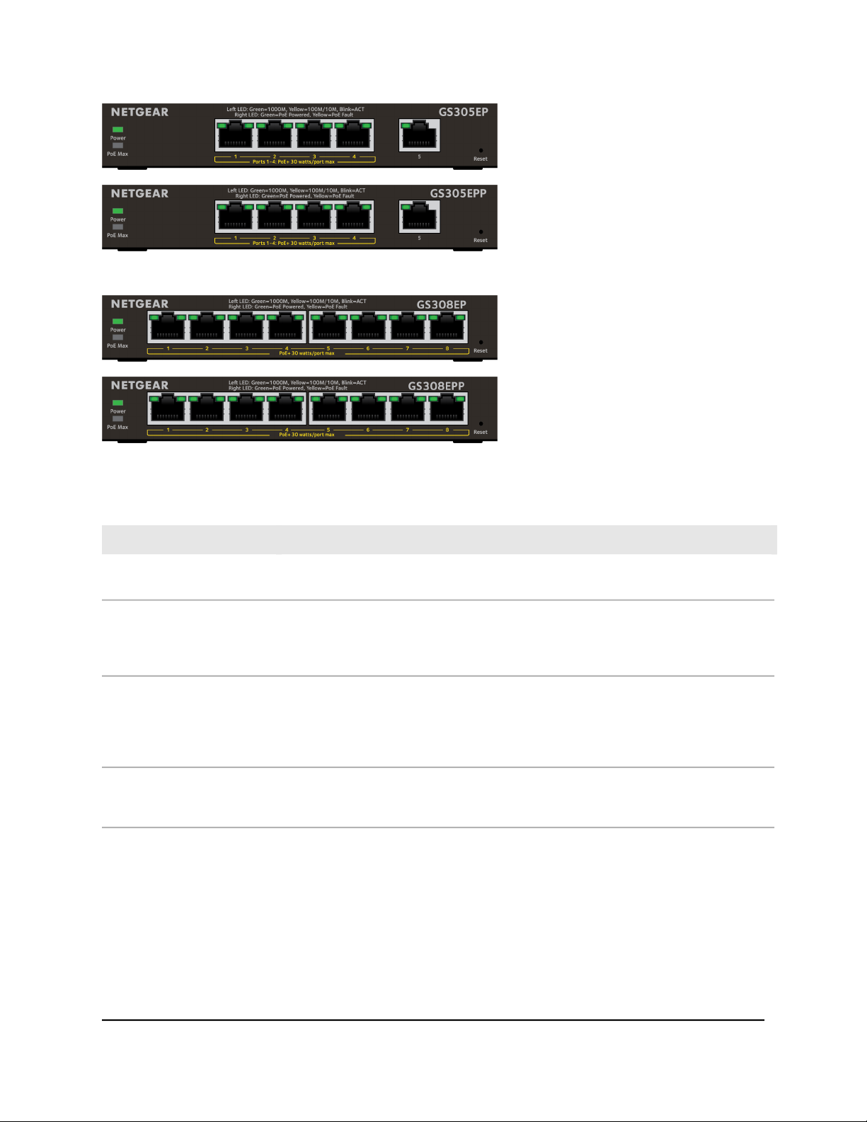
Model GS305EP, GS305EPP, GS308EP, GS308EPP LEDs
This section describes the LED designations of models GS305EP, GS305EPP, GS308EP,
GS308EPP. The port LEDs are located above the ports.
On models GS305EP and GS305EPP, ports 1 through 4 are PoE+ ports. Port 5 is an
Ethernet (uplink) port.
User Manual7Hardware
Page 8
Gigabit Ethernet Plus Switches
On models GS308EP and GS308EPP, all ports 1 through 8 are PoE+ ports.
Table 2. Model GS305EP, GS305EPP, GS308EP, GS308EPP LEDs on the front panel
DescriptionLED
Power LED
PoE Max LED
Left port LED
Right port LED
Solid green: The switch is powered on and operating normally.
Off: Power is not supplied to the switch.
Off: Sufficient (more than 7W of) PoE power is available.
Solid yellow: Less than 7W of PoE power is available.
Blinking yellow: At least once during the previous two minutes, less than 7W of PoE
power was available.
Solid green: 1000 Mbps link on this port.
Blinking green: 1000 Mbps activity on this port.
Solid yellow: A valid 10 Mbps or 100 Mbps port link is established.
Blinking yellow: 100 Mbps or 10 Mbps activity on this port.
Off: No link is detected on this port.
Solid green: The port is delivering PoE power.
Off: The port is not delivering PoE power.
Solid yellow: A PoE fault occurred.
Switch label
The switch label on the bottom panel of the switch shows the serial number, MAC
address, and default login information of the switch.
User Manual8Hardware
Page 9
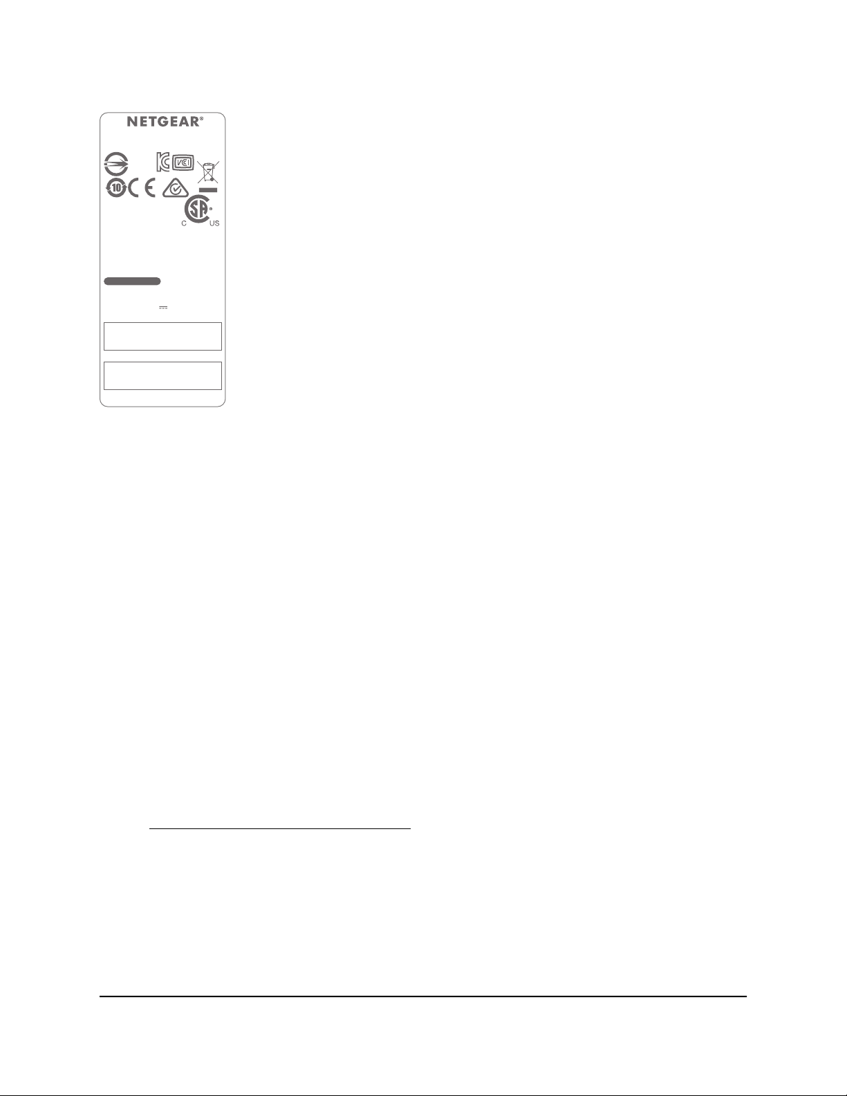
NETGEAR,INC.272-13639-01
SERIAL NUMBER
MAC
Input /輸入: 54V 1.25A
5-Port Gigabit Ethernet Smart
Managed Plus Switch with PoE+
產品名稱: 交換器 Model/型號:GS305EP
R-R-NGR-20300504
This device complies with part 15 of the FCC
Rules. Operation is subject to the following two
conditions: (1) this device may not cause harmful
interference, and (2) this device must accept any
interference received, including interference that
may cause undesired operation.
CAN ICES-3 (B)/NMB-3(B)
NETGEAR INTERNATIONAL LTD
Floor 1, Building 3,
University Technology Centre
Curraheen Road,
Cork, T12EF21, Ireland
D38488
RoHS
password: password
http://192.168.0.239
DEFAULT ACCESS
Made in Thailand
Gigabit Ethernet Plus Switches
Safety instructions and warnings
Use the following safety guidelines to ensure your own personal safety and to help
protect your system from potential damage.
To reduce the risk of bodily injury, electrical shock, fire, and damage to the equipment,
observe the following precautions:
•
This product is designed for indoor use only in a temperature-controlled and
humidity-controlled environment. Note the following:
-
For more information about the environment in which this product must operate,
see the environmental specifications in the appendix or the data sheet.
-
If you want to connect the product to a device located outdoors, the outdoor
device must be properly grounded and surge protected, and you must install an
Ethernet surge protector inline between the indoor product and the outdoor
device. Failure to do so can damage the product.
-
Before connecting the product to outdoor cables or devices, see
https://kb.netgear.com/000057103 for additional safety and warranty information.
Failure to follow these guidelines can result in damage to your NETGEAR product,
which might not be covered by NETGEAR’s warranty, to the extent permissible by
applicable law.
User Manual9Hardware
Page 10

Gigabit Ethernet Plus Switches
Observe and follow service markings:
•
- Do not service any product except as explained in your product documentation.
Some devices should never be opened.
-
If applicable to your product, opening or removing covers that are marked with
the triangular symbol with a lightning bolt can expose you to electrical shock.
We recommend that only a trained technician services components inside these
compartments.
If any of the following conditions occur, unplug the product from the power outlet,
•
and then replace the part or contact your trained service provider:
- Depending on your product, the power adapter, power adapter cable, power
cable, extension cable, or plug is damaged.
-
An object fell into the product.
- The product was exposed to water.
- The product was dropped or damaged.
-
The product does not operate correctly when you follow the operating
instructions.
Keep the product away from radiators and heat sources. Also, do not block cooling
•
vents.
Do not spill food or liquids on your product components, and never operate the
•
product in a wet environment. If the product gets wet, see the appropriate section
in your troubleshooting guide, or contact your trained service provider.
Do not push any objects into the openings of your product. Doing so can cause fire
•
or electric shock by shorting out interior components.
Use the product only with approved equipment.
•
If applicable to your product, allow the product to cool before removing covers or
•
touching internal components.
Operate the product only from the type of external power source indicated on the
•
electrical ratings label. If you are not sure of the type of power source required,
consult your service provider or local power company.
To avoid damaging your system, if your product uses a power supply with a voltage
•
selector, be sure that the selector is set to match the power at your location:
-
115V, 60 Hz in most of North and South America and some Far Eastern countries
such as South Korea and Taiwan
- 100V, 50 Hz in eastern Japan and 100V, 60 Hz in western Japan
-
230V, 50 Hz in most of Europe, the Middle East, and the Far East
User Manual10Hardware
Page 11

Gigabit Ethernet Plus Switches
Be sure that attached devices are electrically rated to operate with the power available
•
in your location.
Depending on your product, use only a supplied power adapter or approved power
•
cable:
If your product uses a power adapter:
-
If you were not provided with a power adapter, contact your local NETGEAR
reseller.
-
The power adapter must be rated for the product and for the voltage and current
marked on the product electrical ratings label.
If your product uses a power cable:
-
If you were not provided with a power cable for your system or for any
AC-powered option intended for your system, purchase a power cable approved
for your country.
-
The power cable must be rated for the product and for the voltage and current
marked on the product electrical ratings label. The voltage and current rating of
the cable must be greater than the ratings marked on the product.
To help prevent electric shock, plug the system and peripheral power cables into
•
properly grounded power outlets.
If applicable to your product, the peripheral power cables are equipped with
•
three-prong plugs to help ensure proper grounding. Do not use adapter plugs or
remove the grounding prong from a cable. If you must use an extension cable, use
a three-wire cable with properly grounded plugs.
Observe extension cable and power strip ratings. Make sure that the total ampere
•
rating of all products plugged into the extension cable or power strip does not
exceed 80 percent of the ampere ratings limit for the extension cable or power strip.
To help protect your system from sudden, transient increases and decreases in
•
electrical power, use a surge suppressor, line conditioner, or uninterruptible power
supply (UPS).
Position system cables, power adapter cables, or power cables carefully. Route
•
cables so that they cannot be stepped on or tripped over. Be sure that nothing rests
on any cables.
Do not modify power adapters, power adapter cables, power cables or plugs. Consult
•
a licensed electrician or your power company for site modifications.
Always follow your local and national wiring rules.
•
User Manual11Hardware
Page 12

2
Install and Access the Switch in Your Network
This chapter describes how you can install and access the switch in your network.
The chapter contains the following sections:
• Set up the switch in your network and power on the switch
• Methods to discover or access the switch
• Access the switch and discover the IP address of the switch
• Set up a fixed IP address for the switch
• Change the language of the device UI
• Change the switch password
• Register the switch
12
Page 13
Gigabit Ethernet Plus Switches
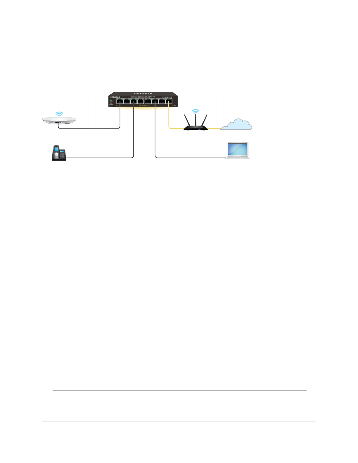
Set up the switch in your network and power on the switch
Figure 1. Example connections
To set up the switch in your network and power on the switch:
1. Connect the LAN (UPLINK) port on the switch to a LAN port on a router that is
connected to the Internet.
On the GS305EP and GS305EPP, use port 5.
On the GS308EP and GS308EPP, use port 8.
2. On the switch, connect your PoE devices to the lowest lowest number ports, starting
with port 1, and then connect any non-PoE devices.
For more information, see PoE considerations for switches that support PoE on page
80.
3. Connect the power adapter to the switch and plug the power adapter into an
electrical outlet.
The power LED lights and the port LEDs for connected devices light.
Methods to discover or access the switch
You can use any of the following methods to discover the switch in your network or
access the switch to configure and manage it:
Computer and web browser. Use a computer and a web browser to discover the
switch in your network and access the device UI of the switch:
Access the switch from a Mac or Windows-based computer using the NETGEAR
•
Switch Discovery Tool on page 14.
Set up a fixed IP address for the switch on page 15.
•
User Manual13Install and Access the Switch in
Your Network
Page 14

Gigabit Ethernet Plus Switches
Access the switch and discover the IP address of the switch
By default, the switch receives an IP address from a DHCP server (or a router that
functions as a DHCP server) in your network.
For information about setting up a fixed (static) IP address on the switch, see Set up a
fixed IP address for the switch on page 15.
Access the switch from a Mac or Windows-based computer using the NETGEAR Switch Discovery Tool
The NETGEAR Switch Discovery Tool (NSDT) lets you discover the switch in your network
and access the device UI of the switch from a Mac or a Windows-based computer.
To install the NSDT, discover the switch in your network, access the switch, and
discover the switch IP address:
1. Download the NSDT by visiting
netgear.com/support/product/netgear-switch-discovery-tool.aspx.
Download either the Mac or Windows version.
2.
Temporarily disable the firewall, Internet security, antivirus programs, or all of these
on the computer that you will use to configure the switch.
3.
Unzip the NSDT files, double-click the .exe or .dmg file (for example,
NETGEAR+Switch+Discovery+Tool+Setup+1.2.102.exe or
NetgearSDT-V1.2.102.dmg), and install the program on your computer.
Depending on your computer setup, the installation process might add the NETGEAR
Switch Discovery Tool icon to the dock of your Mac or the desktop of your
Windows-based computer.
4. Reenable the security services on your computer.
5. Power on the switch.
The DHCP server assigns the switch an IP address.
6. Connect your computer to the same network as the switch.
You can use a WiFi or wired connection. The computer and the switch must be on
the same Layer 2 network.
7. Open the NSDT.
User Manual14Install and Access the Switch in
Your Network
Page 15

Gigabit Ethernet Plus Switches
If the NETGEAR Switch Discovery Tool icon is in the Dock of your Mac or on the
desktop of your Windows-based computer, click or double-click the icon to open
the program.
The initial page displays a menu and a button.
8. From the Choose a connection menu, select the network connection that allows
the NSDT to access the switch.
9. Click the Start Searching button.
The NSDT displays a list of switches that it discovers on the selected network.
For each switch, the tool displays the IP address.
10.
To access the device UI of the switch, click the ADMIN PAGE button.
The login page of the device UI opens.
11. Enter the switch password.
The default password is password. The password is case-sensitive.
The HOME page displays.
The right pane (or, depending on the size of your browser window, the middle pane)
shows the IP address that is assigned to the switch.
Tip: You can copy and paste the IP address into a new shortcut or bookmark it for
quick access on your computer or mobile device. However, if you restart the switch,
a dynamic IP address (assigned by a DHCP server) might change the IP address, and
the bookmark might no longer link to the login page for the switch. When you restart
the switch, you must repeat this procedure so that you can discover the new IP
address of the switch in the network and update your bookmark accordingly. You
can also set up a fixed (static) IP address for the switch (see Set up a fixed IP address
for the switch on page 15 ) to make sure that the new bookmark always links to the
login page for the switch, even after you restart the switch.
Set up a fixed IP address for the switch
By default, the switch receives an IP address from a DHCP server (or a router that
functions as a DHCP server) in your network. However, the DHCP server might not always
issue the same IP address to the switch. For easy access to the switch device UI, you can
Your Network
User Manual15Install and Access the Switch in
Page 16

Gigabit Ethernet Plus Switches
set up a fixed (static) IP address on the switch. This allows you to manage the switch
anytime from a mobile device because the switch IP address remains the same.
To change the IP address of the switch, you can connect to the switch by one of the
following methods:
Through a network connection. If the switch and your computer are connected to
•
the same network (which is the most likely situation), you can change the IP address
of the switch through a network connection (see Set up a fixed IP address for the
switch through a network connection on page 16).
Through a direct connection. In the unlikely situation that the switch is not connected
•
to a network, or for some reason you cannot connect to the switch over a network
connection, you can change the IP address of the switch by using an Ethernet cable
and making a direct connection to the switch (see Set up a fixed IP address for the
switch by connecting directly to the switch off-network on page 17).
Set up a fixed IP address for the switch through a network connection
If the switch and your computer are connected to the same network (which is the most
the likely situation), you can change the IP address of the switch through a network
connection.
To disable the DHCP client of the switch and change the IP address of the switch
to a fixed IP address by using a network connection:
1.
Open a web browser from a computer that is connected to the same network as the
switch.
2. Enter the IP address that is assigned to the switch.
The login page displays.
3. Enter the switch password.
The default password is password. The password is case-sensitive.
The HOME page displays.
The right pane (or, depending on the size of your browser window, the middle pane)
shows the IP address that is assigned to the switch.
4. Select IP Address (DHCP On).
The button bar in the DHCP section displays green because the DHCP client of the
switch is enabled.
5. Click the button in the DHCP section.
The button bar displays gray, indicating that the DHCP client of the switch is disabled,
and the IP address fields become editable.
User Manual16Install and Access the Switch in
Your Network
Page 17

Gigabit Ethernet Plus Switches
6.
Enter the fixed (static) IP address that you want to assign to the switch and the
associated subnet mask and gateway IP address.
You can also either leave the address in the IP Address field as it is (with the IP
address that was issued by the DHCP server) or change the last three digits of the
IP address to an unused IP address.
7.
Write down the complete fixed IP address.
You can bookmark it later.
8. Click the APPLY button.
Your settings are saved. Your switch web session is disconnected when you change
the IP address.
9.
If the login page does not display, in the address field of your web browser, enter
the new IP address of the switch.
The login page displays.
10. For easy access to the device UI, bookmark the page on your computer.
Set up a fixed IP address for the switch by connecting directly to the switch off-network
In the unlikely situation that the switch is not connected to a network, or for some reason
you cannot connect to the switch over a network connection, you can change the IP
address of the switch by using an Ethernet cable and making a direct connection to the
switch.
To disable the DHCP client of the switch and change the IP address of the switch
to a fixed IP address by using a direct connection:
1.
Connect an Ethernet cable from your computer to an Ethernet port on the switch.
2.
Change the IP address of your computer to be in the same subnet as the default IP
address of the switch.
The default IP address of the switch is 192.168.0.239. This means that you must
change the IP address of the computer to be on the same subnet as the default IP
address of the switch (192.168.0.x).
The method to change the IP address on your computer depends on the operating
system of your computer.
3.
Open a web browser from a computer that is connected to the switch directly through
an Ethernet cable.
4.
Enter 192.168.0.239 as the IP address of the switch.
The login page displays.
User Manual17Install and Access the Switch in
Your Network
Page 18

Gigabit Ethernet Plus Switches
5. Enter the switch password.
The default password is password. The password is case-sensitive.
The HOME page displays.
The right pane (or, depending on the size of your browser window, the middle pane)
shows the IP address that is assigned to the switch.
6. Select IP Address (DHCP On).
The button bar in the DHCP section displays green because the DHCP client of the
switch is enabled.
7. Click the button in the DHCP section.
The button bar displays gray, indicating that the DHCP client of the switch is disabled,
and the IP address fields become editable.
8.
Enter the fixed (static) IP address that you want to assign to the switch and the
associated subnet mask and gateway IP address.
9.
Write down the complete fixed IP address.
You can bookmark it later.
10. Click the APPLY button.
Your settings are saved. Your switch web session is disconnected when you change
the IP address.
11.
Disconnect the switch from your computer and install the switch in your network.
For more information, see Set up the switch in your network and power on the switch
on page 13.
12. Restore your computer to its original IP address.
13.
Verify that you can connect to the switch with its new IP address:
a.
Open a web browser from a computer that is connected to the same network as
the switch.
b. Enter the new IP address that you assigned to the switch.
The login page displays.
c. Enter the switch password.
The default password is password. The password is case-sensitive.
The HOME page displays.
Your Network
User Manual18Install and Access the Switch in
Page 19

Gigabit Ethernet Plus Switches
Change the language of the device UI
By default, the language of the device UI is set to Auto so that the switch can automatically
detect the language. However, you can set the language to a specific one.
To change the language of the device UI:
1.
Open a web browser from a computer that is connected to the same network as the
switch or to the switch directly through an Ethernet cable.
2. Enter the IP address that is assigned to the switch.
The login page displays.
3. Enter the switch password.
The default password is password. The password is case-sensitive.
The HOME page displays.
4.
Select System Info.
The System Info fields display.
5. From the Language menu, select a language.
6. Click the APPLY button.
A pop-up warning window opens.
7. Click the CONTINUE button.
Your settings are saved and the language changes.
Change the switch password
The default password to access the device UI of the switch is password. We recommend
that you change this password to a more secure password. The ideal password contains
no dictionary words from any language and contains uppercase and lowercase letters,
numbers, and symbols. It can be up to 20 characters.
To change the switch password:
1.
Open a web browser from a computer that is connected to the same network as the
switch or to the switch directly through an Ethernet cable.
2. Enter the IP address that is assigned to the switch.
The login page displays.
3. Enter the switch password.
User Manual19Install and Access the Switch in
Your Network
Page 20

Gigabit Ethernet Plus Switches
The default password is password. The password is case-sensitive.
The HOME page displays.
4.
From the menu at the top of the page, select SETTINGS.
5.
From the menu on the left, select CHANGE PASSWORD.
The CHANGE PASSWORD page displays.
6.
In the Current Password field, type the current password for the switch.
7.
Type the new password in the New Password field and in the Retype New Password
field.
8. Click the APPLY button.
Your settings are saved. Keep the new password in a secure location so that you can
access the switch in the future.
Register the switch
Registering the switch allows you to receive email alerts and streamlines the technical
support process. You can log in to your NETGEAR account at my.netgear.com to register
your switch, or you can also register the switch through the device UI, in which case the
switch must be connected to the Internet.
To register the switch through the device UI:
1.
Open a web browser from a computer that is connected to the same network as the
switch, or connected directly to the switch through an Ethernet cable.
2. Enter the IP address that is assigned to the switch.
A login window opens.
3. Enter the device management password.
The password is the one that you specified the first time that you logged in. The
password is case-sensitive.
The HOME page displays.
4.
From the menu at the top of the page, select SETTINGS.
5.
From the menu on the left, select PRODUCT REGISTRATION.
The PRODUCT REGISTRATION page displays.
6. Click the REGISTER button.
The switch contacts the registration server.
7. Follow the onscreen process to register the switch.
Your Network
User Manual20Install and Access the Switch in
Page 21

3
Optimize the Switch Performance
This chapter describes how you can optimize the performance of the switch.
The chapter contains the following sections:
• Set the quality of service mode and port rate limits
• Manage individual port settings
21
Page 22

Gigabit Ethernet Plus Switches
Set the quality of service mode and port rate limits
You can manually set the Quality of Service (QoS) modes to manage traffic:
Port-based QoS mode. Lets you set the priority (low, medium, high, or critical) for
•
individual port numbers and lets you set rate limits for incoming and outgoing traffic
for individual ports. If broadcast filtering is enabled, you can also set the storm control
rate for incoming traffic for individual ports.
802.1P/DSCP QoS mode. Applies pass-through prioritization that is based on
•
tagged packets and lets you set rate limits for incoming and outgoing traffic for
individual ports. If broadcast filtering is enabled, you can also set the storm control
rate for incoming traffic for individual ports.
This QoS mode applies only to devices that support 802.1P and Differentiated
Services Code Point (DSCP) tagging. For devices that do not support 802.1P and
DSCP tagging, ports are not prioritized but the configured rate limit is still applied.
You can limit the rate of incoming traffic, outgoing traffic, or both on a port to prevent
the port (and the device that is attached to it) from taking up too much bandwidth on
the switch. Rate limiting, which you can set for individual ports in either QoS mode,
simply means that the switch slows down all traffic on a port so that traffic does not
exceed the limit that you set for that port. If you set the rate limit on a port too low, you
might, for example, see degraded video stream quality, sluggish response times during
online activity, and other problems.
Use port-based quality of service and set port priorities
802.1P/DSCP is the default QoS mode on the switch, but you can also set port-based
QoS.
For each port, you can set the priority and the rate limits for both incoming and outgoing
traffic:
Port priority. The switch services traffic from ports with a critical priority before traffic
•
from ports with a high, medium, or low priority. Similarly, the switch services traffic
from ports with a high priority before traffic from ports with a medium or low priority.
If severe network congestion occurs, the switch might drop packets with a low priority.
Port rate limits. The switch accepts traffic on a port at the rate (the speed of the
•
data transfer) that you set for incoming traffic on that port. The switch transmits traffic
from a port at the rate that you set for outgoing traffic on that port. You can select
each rate limit as a predefined data transfer threshold from 512 Kbps to 512 Mbps.
Performance
User Manual22Optimize the Switch
Page 23

Gigabit Ethernet Plus Switches
Note: If you set a port rate limit, the actual rate might fluctuate, depending on the type
of traffic that the port is processing.
To use the Port-based QoS mode and set the priority and rate limits for ports:
1.
Open a web browser from a computer that is connected to the same network as the
switch, or connected directly to the switch through an Ethernet cable.
2. Enter the IP address that is assigned to the switch.
A login window opens.
3. Enter the device management password.
The password is the one that you specified the first time that you logged in. The
password is case-sensitive.
The HOME page displays.
4.
From the menu at the top of the page, select SWITCHING > QOS .
The Quality of Service (QoS) page displays.
5.
If the selection from the QoS Mode menu is 802.1P/DSCP, do the following to
change the selection to Port-based:
a. From the QoS Mode menu, select Port-Based.
A pop-up warning window opens.
b. Click the CONTINUE button.
The pop-up window closes.
Note: For information about broadcast filtering, see Manage broadcast filtering
and set port storm control rate limits on page 25.
6.
To set the port priorities, do the following:
a. Click the PRIORITY tab.
b. Click the purple pencil icon.
The EDIT PRIORITY page displays.
c.
For each port for which you want to set the priority, select Low, Medium, High,
or Critical from the individual menu for the port.
The default selection is High.
d. Click the APPLY button.
Your settings are saved and the EDIT PRIORITY page closes.
7.
To set rate limits, do the following:
a. In SWITCHING > QOS, click the RATE LIMITS tab.
b. Click the purple pencil icon.
Performance
User Manual23Optimize the Switch
Page 24

Gigabit Ethernet Plus Switches
The EDIT RATE LIMITS page displays.
c.
For each port for which you want to set rate limits, select the rate in Kbps or Mbps
from the individual In Limits and Out Limits menus for the port.
The default selection is No Limit.
d. Click the APPLY button.
Your settings are saved and the EDIT RATE LIMITS page closes.
Use 802.1P/DSCP quality of service
In the 802.1P/DSCP QoS mode, the switch uses the 802.1P or DSCP information in the
header of an incoming packet to prioritize the packet. With this type of QoS, you cannot
control the port prioritization on the switch because the device that sends the traffic
(that is, the packets) to the switch prioritizes the traffic. However, you can set the rate
limits for individual ports on the switch.
The switch accepts traffic on a port at the rate (the speed of the data transfer) that you
set for incoming traffic on that port. The switch transmits traffic from a port at the rate
that you set for outgoing traffic on that port. You can select each rate limit as a predefined
data transfer threshold from 512 Kbps to 512 Mbps.
To use 802.1P/DSCP QoS mode and set the rate limits for ports:
1.
Open a web browser from a computer that is connected to the same network as the
switch, or connected directly to the switch through an Ethernet cable.
2. Enter the IP address that is assigned to the switch.
A login window opens.
3. Enter the device management password.
The password is the one that you specified the first time that you logged in. The
password is case-sensitive.
The HOME page displays.
4.
From the menu at the top of the page, select SWITCHING > QOS .
The Quality of Service (QoS) page displays.
5.
If the selection from the QoS Mode menu is Port-based, do the following to change
the selection to 802.1P/DSCP:
a.
From the QoS Mode menu, select 802.1P/DSCP.
A pop-up warning window opens.
b. Click the CONTINUE button.
The pop-up window closes.
Performance
User Manual24Optimize the Switch
Page 25

Gigabit Ethernet Plus Switches
Note: For information about broadcast filtering, see Manage broadcast filtering
and set port storm control rate limits on page 25.
6.
To set rate limits, do the following:
a. Click the RATE LIMITS tab.
If broadcast filtering is disabled, only the RATE LIMITS tab displays.
b. Click the purple pencil icon.
The EDIT RATE LIMITS page displays.
c.
For each port for which you want to set rate limits, select the rate in Kbps or Mbps
from the individual In Limits and Out Limits menus for the port.
The default selection is No Limit.
d. Click the APPLY button.
Your settings are saved and the EDIT RATE LIMITS page closes.
Manage broadcast filtering and set port storm control rate limits
A broadcast storm is a massive transmission of broadcast packets that are forwarded
to every port on the switch. If they are not blocked, broadcast storm packets can delay
or halt the transmission of other data and cause problems. However, you can block
broadcast storms on the switch.
You can also set storm control rate limits for each port. Storm control measures the
incoming broadcast, multicast, and unknown unicast frame rates separately on each
port, and discards the frames if the rate that you set for the port is exceeded. By default,
no storm control rate limit is set for a port. You can select each storm control rate limit
as a predefined data transfer threshold from 512 Kbps to 512 Mbps.
To manage broadcast filtering and set the storm control rate limits for ports:
1.
Open a web browser from a computer that is connected to the same network as the
switch, or connected directly to the switch through an Ethernet cable.
2. Enter the IP address that is assigned to the switch.
A login window opens.
3. Enter the device management password.
The password is the one that you specified the first time that you logged in. The
password is case-sensitive.
The HOME page displays.
4.
From the menu at the top of the page, select SWITCHING > QOS .
Performance
User Manual25Optimize the Switch
Page 26

Gigabit Ethernet Plus Switches
The Quality of Service (QoS) page displays.
5.
If the selection from the QoS Mode menu is not the QoS mode that you want to
configure, do the following to change the QoS mode:
a.
From the QoS Mode menu, select Port-Based or 802.1P/DSCP.
A pop-up warning window opens.
b. Click the CONTINUE button.
The pop-up window closes and the QoS mode is changed.
6. Click the Broadcast Filtering button.
When broadcast filtering is enabled, the button bar displays green.
7. Click the APPLY button.
Broadcast filtering is enabled. The STORM CONTROL RATE tab displays next to
the RATE LIMITS tab.
8.
To set storm control rate limits, do the following:
a. Click the STORM CONTROL RATE tab.
b. Click the purple pencil icon.
The EDIT STORM CONTROL RATE options display.
c.
For each port for which you want to set storm control rate limits, select the rate
in Kbps or Mbps from the individual menu for the port.
The default selection is No Limit.
d. Click the APPLY button.
Your settings are saved and the EDIT STORM CONTROL RATE tab displays your
new settings.
Manage individual port settings
For each individual port, you can set the port priority, set rate limits for incoming and
outgoing traffic, set the port speed (by default, the speed is set automatically), enable
flow control, and change the port name label.
Set rate limits for a port
You can limit the rate of incoming (ingress) traffic, outgoing (egress) traffic, or both on
a port to prevent the port (and the device that is attached to it) from taking up too much
bandwidth on the switch. Rate limiting simply means that the switch slows down all
traffic on a port so that traffic does not exceed the limit that you set for that port. If you
User Manual26Optimize the Switch
Performance
Page 27

Gigabit Ethernet Plus Switches
set the rate limit on a port too low, you might, for example, see degraded video stream
quality, sluggish response times during online activity, and other problems.
You also can set port rate limits (the same feature) as part of the Quality of Service
configuration on the switch (see Set the quality of service mode and port rate limits on
page 22).
To set rate limits for incoming and outgoing traffic on a port:
1.
Open a web browser from a computer that is connected to the same network as the
switch, or connected directly to the switch through an Ethernet cable.
2. Enter the IP address that is assigned to the switch.
A login window opens.
3. Enter the device management password.
The password is the one that you specified the first time that you logged in. The user
name and password are case-sensitive.
The HOME page displays.
The PORT STATUS pane displays on the right or the bottom of the HOME page,
depending on the size of your browser window.
A port that is in use shows as UP. A port that is not in use shows as AVAILABLE.
4. Select the port.
The pane displays detailed information about the port.
5. Click the EDIT button.
The EDIT PORT page displays for the selected port.
If the QoS mode on the switch is Port-based (the default setting), the Priority menu
displays on the page. If the QoS mode is 802.1P/DSCP, the Priority menu does not
display.
6. From the In Rate Limit menu, Out Rate Limit menu, or both, select the rate in Kbps
or Mbps.
The default selection is No Limit.
7. Click the APPLY button.
Your settings are saved.
Set the priority for a port
If the QoS mode on the switch is Port-based (the default setting), you can set the priority
for a port.
User Manual27Optimize the Switch
Performance
Page 28

Gigabit Ethernet Plus Switches
The switch services traffic from ports with a critical priority before traffic from ports with
a high, medium, or low priority. Similarly, the switch services traffic from ports with a
high priority before traffic from ports with a medium or low priority. If severe network
congestion occurs, the switch might drop packets with a low priority.
You also can set the priority for a port (the same feature) as part of the Quality of Service
configuration on the switch (see Use port-based quality of service and set port priorities
on page 22).
1.
Open a web browser from a computer that is connected to the same network as the
switch, or connected directly to the switch through an Ethernet cable.
2. Enter the IP address that is assigned to the switch.
A login window opens.
3. Enter the device management password.
The password is the one that you specified the first time that you logged in. The user
name and password are case-sensitive.
The HOME page displays.
The PORT STATUS pane displays on the right or the bottom of the HOME page,
depending on the size of your browser window.
A port that is in use shows as UP. A port that is not in use shows as AVAILABLE.
4. Select the port.
The pane displays detailed information about the port.
5. Click the EDIT button.
The EDIT PORT page displays for the selected port.
If the QoS mode on the switch is Port-based (the default setting), the Priority menu
displays on the page. If the QoS mode is 802.1P/DSCP, the Priority menu does not
display.
6. From the Priority menu, select Low, Medium, High, or Critical.
The default selection is High.
7. Click the APPLY button.
Your settings are saved.
Manage flow control for a port
IEEE 802.3x flow control works by pausing a port if the port becomes oversubscribed
(that is, the port receives more traffic than it can process) and dropping all traffic for
small bursts of time during the congestion condition.
User Manual28Optimize the Switch
Performance
Page 29

Gigabit Ethernet Plus Switches
You can enable or disable flow control for an individual port. By default, flow control is
disabled for all ports.
To manage flow control for a port:
1.
Open a web browser from a computer that is connected to the same network as the
switch, or connected directly to the switch through an Ethernet cable.
2. Enter the IP address that is assigned to the switch.
A login window opens.
3. Enter the device management password.
The password is the one that you specified the first time that you logged in. The user
name and password are case-sensitive.
The HOME page displays.
The PORT STATUS pane displays on the right or the bottom of the HOME page,
depending on the size of your browser window.
A port that is in use shows as UP. A port that is not in use shows as AVAILABLE.
4. Select the port.
The pane displays detailed information about the port.
5. Click the EDIT button.
The EDIT PORT page displays for the selected port.
If the QoS mode on the switch is Port-based (the default setting), the Priority menu
displays on the page. If the QoS mode is 802.1P/DSCP, the Priority menu does not
display.
6.
In the Flow Control section, enable or disable flow control by clicking the button.
When flow control is enabled, the button bar displays green.
7. Click the APPLY button.
Your settings are saved.
Change the speed for a port or disable a port
By default, the port speed on all ports is set automatically (that is, the setting is Auto)
after the switch determines the speed using autonegotiation with the linked device. We
recommend that you leave the Auto setting for the ports. However, you can select a
specific port speed setting for each port or disable a port by shutting it down manually.
Performance
User Manual29Optimize the Switch
Page 30

Gigabit Ethernet Plus Switches
To change the speed for a port or disable a port:
1.
Open a web browser from a computer that is connected to the same network as the
switch, or connected directly to the switch through an Ethernet cable.
2. Enter the IP address that is assigned to the switch.
A login window opens.
3. Enter the device management password.
The password is the one that you specified the first time that you logged in. The user
name and password are case-sensitive.
The default password is password. The password is case-sensitive.
The HOME page displays.
The PORT STATUS pane displays on the right or the bottom of the HOME page,
depending on the size of your browser window.
A port that is in use shows as UP. A port that is not in use shows as AVAILABLE.
4. Select the port.
The pane displays detailed information about the port.
5. Click the EDIT button.
The EDIT PORT page displays for the selected port.
If the QoS mode on the switch is Port-based (the default setting), the Priority menu
displays on the page. If the QoS mode is 802.1P/DSCP, the Priority menu does not
display.
6.
Select one of the following options from the Speed menu:
Auto. The port speed is set automatically after the switch determines the speed
•
using autonegotiation with the linked device. This is the default setting.
Disable. The port is shut down (blocked).
•
10M half. The port is forced to function at 10 Mbps with half-duplex.
•
10M full. The port is forced to function at 10 Mbps with full-duplex.
•
100M half. The port is forced to function at 100 Mbps with half-duplex.
•
100M full. The port is forced to function at 100 Mbps with full-duplex.
•
Note: You cannot select Gigabit Ethernet as the port speed. However, if the setting
from the Speed menu is Auto, the switch can use autonegotiation to automatically
set the port speed to Gigabit Ethernet if the linked device supports that speed.
7. Click the APPLY button.
User Manual30Optimize the Switch
Performance
Page 31

Gigabit Ethernet Plus Switches
Your settings are saved.
Add or change the name label for a port
You can add or change a name label for a port. these name labels. Adding or changing
a name label does not change the nature of a port, that is, it is just a label.
To add or change a name label for a port:
1.
Open a web browser from a computer that is connected to the same network as the
switch, or connected directly to the switch through an Ethernet cable.
2. Enter the IP address that is assigned to the switch.
A login window opens.
3. Enter the device management password.
The password is the one that you specified the first time that you logged in. The user
name and password are case-sensitive.
The HOME page displays.
The PORT STATUS pane displays on the right or the bottom of the HOME page,
depending on the size of your browser window.
A port that is in use shows as UP. A port that is not in use shows as AVAILABLE.
4. Select the port.
The pane displays detailed information about the port.
5. Click the EDIT button.
The EDIT PORT page displays for the selected port.
If the QoS mode on the switch is Port-based (the default setting), the Priority menu
displays on the page. If the QoS mode is 802.1P/DSCP, the Priority menu does not
display.
6.
In the Port Name field, type a name label for the port.
The name label can be from 1 to 16 characters.
7. Click the APPLY button.
Your settings are saved.
Performance
User Manual31Optimize the Switch
Page 32

4
Use VLANS for Traffic Segmentation
This chapter describes how you can use VLANs to segment traffic on the switch.
The chapter contains the following sections:
• VLAN overview
• Activate the Basic Port-Based VLAN mode and assign VLANs
• Manage advanced port-based VLANs
• Manage basic 802.1Q VLANs
• Manage advanced 802.1Q VLANs
• Deactivate a port-based or 802.1Q VLAN mode and delete all VLANs
32
Page 33

Gigabit Ethernet Plus Switches
VLAN overview
Virtual LANs (VLANs) are made up of networked devices that are grouped logically into
separate networks. You can group ports on a switch to create a virtual network made
up of the devices connected to the ports.
You can group ports in VLANs using either port-based or 802.1Q criteria:
Port-based VLANs. Assign ports to virtual networks. Ports with the same VLAN ID
•
are placed in the same VLAN. This feature provides an easy way to partition a network
into private subnetworks.
If the switch is the only switch in your network and you do not need a VLAN to function
across multiple network devices (such as a router, another switch, a WiFi AP, or any
network device that supports VLANs), we recommend that you use a port-based
VLAN. If you need a single VLAN on a single port (other than the uplink port), use
the basic port-based VLAN configuration. If you need multiple VLANs on a single
port, use the advanced port-based VLAN configuration.
The switch supports the following port-based VLAN modes:
-
Basic Port-Based VLAN. In a basic port-based VLAN configuration, ports with
the same VLAN ID are placed into the same VLAN. Except for the uplink port,
you can assign each port to a single VLAN only. The number of VLANs is limited
to the number of ports on the switch.
-
Advanced Port-Based VLAN. In an advanced port-based VLAN configuration,
ports with the same VLAN ID are also placed into the same VLAN, but you can
assign a single port to multiple VLANs.
802.1Q VLANs. Create virtual networks using the IEEE 802.1Q standard. 802.1Q
•
uses a VLAN tagging system to determine which VLAN an Ethernet frame belongs
to. To use an 802.1Q VLAN that is set up on another device, you must know the
VLAN ID.
If you need a VLAN to function across multiple network devices (such as a router,
another switch, a WiFi AP, or any network device that supports VLANs), we
recommend that you use an 802.1Q VLAN. If you do not need to customize tagging
on a single port and you do not need a voice VLAN, use the basic 802.1Q VLAN
configuration. If you do need to customize tagging on a single port or you do need
a voice VLAN, use the advanced 802.1Q VLAN configuration.
The switch supports the following 802.1Q VLAN modes:
-
Basic 802.1Q VLAN. In a basic 802.1Q VLAN configuration, VLAN 1 is added to
the switch and all ports (1 through 5 for the GS305EP or GS305EPP, and 1 through
8 for the GS308EP or GS308EPP) function in access mode as members of VLAN
1. You can change the mode for a port to trunk mode, you can add more VLANs,
and you can assign a different VLAN to a port. A port that functions in access
Segmentation
User Manual33Use VLANS for Traffic
Page 34

Gigabit Ethernet Plus Switches
mode can belong to a single VLAN only and does not tag the traffic that it
processes. A port that functions in trunk mode automatically belongs to all VLANs
on the switch and tags the traffic that it processes.
-
Advanced 802.1Q VLAN. In an advanced 802.1Q VLAN configuration, VLAN 1
is added to the switch and all ports (1 through 5 for the GS305EP or GS305EPP,
and 1 through 8 for the GS308EP or GS308EPP) are untagged members of
VLAN 1. You can tag ports, untag ports, exclude ports, add more VLANs, assign
a different VLAN to a port, manage port PVIDs, and manage a voice VLAN.
The following table provides an overview of VLAN features that are supported on the
switch.
Table 3. Supported VLAN modes for the GS305EP and GS305EPP
VLAN Feature
VLANs
single port
Basic
Port-Based VLAN
Advanced
Port-Based VLAN
Basic
802.1Q VLAN
Table 4. Supported VLAN modes for the GS308EP and GS308EPP
VLAN Feature
VLANs
Basic
Port-Based VLAN
Advanced
Port-Based VLAN
Basic
802.1Q VLAN
Advanced
802.1Q VLAN
646455Total number of
YesYes (trunk port only)NoNoEgress tagging
YesYes (trunk port only)YesNoMultiple VLANs on a
YesNoNoNoVoice VLAN
Advanced
802.1Q VLAN
646488Total number of
YesYes (trunk port only)NoNoEgress tagging
Segmentation
User Manual34Use VLANS for Traffic
Page 35

Gigabit Ethernet Plus Switches
Table 4. Supported VLAN modes for the GS308EP and GS308EPP (Continued)
VLAN Feature
single port
Basic
Port-Based VLAN
Advanced
Port-Based VLAN
Basic
802.1Q VLAN
Advanced
802.1Q VLAN
YesYes (trunk port only)YesNoMultiple VLANs on a
YesNoNoNoVoice VLAN
Activate the Basic Port-Based VLAN mode and assign VLANs
By default, all types of VLANs are disabled on the switch.
When you activate the Basic Port-Based VLAN mode, all VLANs are added to the switch,
and all ports are made members of VLAN 1. This is the default VLAN in the Basic
Port-Based VLAN mode.
In the Basic Port-Based VLAN mode, you can assign each port (other than the uplink
port) to a single VLAN only.
To activate the Basic Port-Based VLAN mode and assign VLANs:
1.
Open a web browser from a computer that is connected to the same network as the
switch, or connected directly to the switch through an Ethernet cable.
2. Enter the IP address that is assigned to the switch.
A login window opens.
3. Enter the device management password.
The password is the one that you specified the first time that you logged in. The
password is case-sensitive.
The HOME page displays.
4.
From the menu at the top of the page, select SWITCHING.
The QOS page displays.
5.
From the menu on the left, select VLAN.
The VLAN page displays.
6. In the Basic Port-Based VLAN section, click the ACTIVATE MODE button.
A pop-up window opens, informing you that the current VLAN settings will be lost.
7. Click the CONTINUE button.
Segmentation
User Manual35Use VLANS for Traffic
Page 36

Gigabit Ethernet Plus Switches
Your settings are saved and the pop-up window closes. By default, all VLANs are
added and each port is a member of VLAN 1.
8.
To assign one or more ports to other VLANs, do the following:
a.
For each port that you want to assign to another VLAN, select a VLAN ID from
the VLAN menu for the individual port.
Each port can be assigned to a single VLAN only. However, for the port that you
want to use as the uplink port to the Internet connection or a server, select All
from the VLAN menu for the individual port.
b. Click the APPLY button.
Your settings are saved.
Manage advanced port-based VLANs
In an advanced port-based VLAN configuration, ports with the same VLAN ID are placed
into the same VLAN, but you can assign a single port to multiple VLANs.
For more information about port-based VLANs, see the following sections:
• Activate the Advanced Port-Based VLAN Mode
• Create an advanced port-based VLAN
• Change an advanced port-based VLAN
• Delete an advanced port-based VLAN
Activate the Advanced Port-Based VLAN Mode
By default, all types of VLANs are disabled on the switch.
When you activate the Advanced Port-Based VLAN mode, VLAN 1 is added to the switch
and all ports are made members of VLAN 1. This is the default VLAN in the Advanced
Port-Based VLAN mode.
To activate the Advanced Port-Based VLAN mode:
1.
Open a web browser from a computer that is connected to the same network as the
switch, or connected directly to the switch through an Ethernet cable.
2. Enter the IP address that is assigned to the switch.
A login window opens.
3. Enter the device management password.
The password is the one that you specified the first time that you logged in. The
password is case-sensitive.
The HOME page displays.
Segmentation
User Manual36Use VLANS for Traffic
Page 37

Gigabit Ethernet Plus Switches
4.
From the menu at the top of the page, select SWITCHING.
The QOS page displays.
5.
From the menu on the left, select VLAN.
The VLAN page displays.
6. In the Advanced Port-Based VLAN section, click the ACTIVATE MODE button.
A pop-up window opens, informing you that the current VLAN settings will be lost.
7. Click the CONTINUE button.
Your settings are saved and the pop-up window closes. By default, VLAN 1 is added
and all ports are members of VLAN 1.
For information about creating an advanced port-based VLAN, see Create an
advanced port-based VLAN on page 37.
Create an advanced port-based VLAN
An advanced port-based VLAN configuration lets you create VLANs and assign ports
on the switch to a VLAN. The number of VLANs is limited to the number of ports on the
switch. In an advanced port-based VLAN configuration, one port can be a member of
multiple VLANs.
By default, all ports are members of VLAN 1, but you can change the VLAN assignment.
To create an advanced port-based VLAN and assign ports as members:
1.
Open a web browser from a computer that is connected to the same network as the
switch, or connected directly to the switch through an Ethernet cable.
2. Enter the IP address that is assigned to the switch.
A login window opens.
3. Enter the device management password.
The password is the one that you specified the first time that you logged in. The
password is case-sensitive.
The HOME page displays.
4.
From the menu at the top of the page, select SWITCHING.
The QOS page displays.
5.
From the menu on the left, select VLAN.
The VLAN page displays.
If you did not yet activate the Advanced Port-Based VLAN mode, see Activate the
Advanced Port-Based VLAN Mode on page 36.
User Manual37Use VLANS for Traffic
Segmentation
Page 38

Gigabit Ethernet Plus Switches
6. In the Advanced Port-Based VLAN section, click the ADD VLAN button.
7.
Specify the settings for the new VLAN:
VLAN Name. Enter a name from 1 to 14 characters.
•
VLAN ID. Enter a number from 1 to the total number of ports on the switch.
•
Ports. Select the ports that you want to include in the VLAN through a combination
•
of the following actions:
-
Click the icon for an unselected port to add the port to the VLAN.
-
Click the icon for a selected port to remove the port from the VLAN.
- Click the Select All link to add all ports to the VLAN.
-
Click the Remove All link to remove all selected ports from the VLAN.
The icon for a selected port displays purple.
Note: If ports are members of the same LAG, you must assign them to the same
VLAN.
8. Click the APPLY button.
Your settings are saved. The new VLAN is added to the VLAN table, which shows
the port members for each VLAN.
Change an advanced port-based VLAN
You can change the settings for an existing advanced port-based VLAN.
To change an advanced port-based VLAN:
1.
Open a web browser from a computer that is connected to the same network as the
switch, or connected directly to the switch through an Ethernet cable.
2. Enter the IP address that is assigned to the switch.
A login window opens.
3. Enter the device management password.
The password is the one that you specified the first time that you logged in. The
password is case-sensitive.
The HOME page displays.
4.
From the menu at the top of the page, select SWITCHING.
The QOS page displays.
5.
From the menu on the left, select VLAN.
Segmentation
User Manual38Use VLANS for Traffic
Page 39

Gigabit Ethernet Plus Switches
The VLAN page displays.
6. In the Advanced Port-Based VLAN section, click the VLAN that you want to change
(you can click anywhere in the row for the VLAN) and click the EDIT button.
The Advanced Port-Based VLAN pane displays.
7.
Change the settings for the VLAN:
VLAN Name. Enter a name from 1 to 14 characters.
•
You cannot change the VLAN ID. If you need to change the VLAN ID, delete the
VLAN and create a new VLAN with another VLAN ID.
Ports. Select the ports that you want to include in the VLAN through a combination
•
of the following actions:
-
Click the icon for an unselected port to add the port to the VLAN.
-
Click the icon for a selected port to remove the port from the VLAN.
- Click the Select All link to add all ports to the VLAN.
-
Click the Remove All link to remove all selected ports from the VLAN.
The icon for a selected port displays purple.
Note: If ports are members of the same LAG, you must assign them to the same
VLAN.
8. Click the APPLY button.
Your settings are saved. The modified VLAN shows in the VLAN table.
Delete an advanced port-based VLAN
You can delete an advanced port-based VLAN that you no longer need. You cannot
delete the default VLAN.
Note: If you deactivate the basic or advanced port-based VLAN mode, all port-based
VLANs are deleted.
To delete an advanced port-based VLAN:
1.
Open a web browser from a computer that is connected to the same network as the
switch, or connected directly to the switch through an Ethernet cable.
2. Enter the IP address that is assigned to the switch.
A login window opens.
3. Enter the device management password.
User Manual39Use VLANS for Traffic
Segmentation
Page 40

Gigabit Ethernet Plus Switches
The password is the one that you specified the first time that you logged in. The
password is case-sensitive.
The HOME page displays.
4.
From the menu at the top of the page, select SWITCHING.
The QOS page displays.
5.
From the menu on the left, select VLAN.
The VLAN page displays.
6. In the Advanced Port-Based VLAN section, click the VLAN that you want to delete
(you can click anywhere in the row for the VLAN).
7. Click the DELETE button.
Your settings are saved. The VLAN is deleted.
Manage basic 802.1Q VLANs
In a basic 802.1Q VLAN configuration, VLAN 1 is added to the switch and all ports
function in access mode as members of VLAN 1. You can change the mode for a port
to trunk mode, you can add more VLANs, and you can assign a different VLAN to a port.
After you activate the Basic 802.1Q VLAN mode, you can create VLANs, assign the
VLANs to ports that function in access mode, and assign the trunk mode, which carries
traffic for all VLANs.
For more information about basic 802.1Q VLANs, see the following sections:
• Activate the Basic 802.1Q VLAN mode
• Create a basic 802.1Q VLAN and assign ports as members
• Assign the port mode in a basic 802.1Q VLAN configuration
• Change a basic 802.1Q VLAN
• Delete a basic 802.1Q VLAN
Activate the Basic 802.1Q VLAN mode
By default, all types of VLANs are disabled on the switch.
When you activate the Basic 802.1Q VLAN mode, VLAN 1 is added to the switch and
all ports function in access mode (rather than trunk mode) as untagged members of
VLAN 1. This is the default VLAN in the Basic 802.1Q VLAN mode.
User Manual40Use VLANS for Traffic
Segmentation
Page 41

Gigabit Ethernet Plus Switches
To activate the Basic 802.1Q VLAN mode:
1.
Open a web browser from a computer that is connected to the same network as the
switch, or connected directly to the switch through an Ethernet cable.
2. Enter the IP address that is assigned to the switch.
A login window opens.
3. Enter the device management password.
The password is the one that you specified the first time that you logged in. The
password is case-sensitive.
The HOME page displays.
4.
From the menu at the top of the page, select SWITCHING.
The QOS page displays.
5.
From the menu on the left, select VLAN.
The VLAN page displays.
6. In the Basic 802.1Q VLAN section, click the ACTIVATE MODE button.
A pop-up window opens, informing you that the current VLAN settings will be lost.
7. Click the CONTINUE button.
Your settings are saved and the pop-up window closes. By default, VLAN 1 is added.
For information about adding VLANs, see Create a basic 802.1Q VLAN and assign
ports as members on page 41.
For all ports, the default selection from the Mode menu is Access. For more
information about access mode and trunk mode, see Assign the port mode in a basic
802.1Q VLAN configuration on page 43.
8.
If you already determined which ports must function in trunk mode, for those ports,
select Trunk (uplink) from the Mode menu.
9. Click the SAVE button.
Your settings are saved.
Create a basic 802.1Q VLAN and assign ports as members
A basic 802.1Q VLAN configuration lets you create VLANs and assign ports on the switch
to a VLAN. A port that functions in access mode can be member of a single VLAN only.
The number of VLANs is limited to the number of ports on the switch. You can assign
a VLAN ID number in the range of 1–4093.
User Manual41Use VLANS for Traffic
Segmentation
Page 42

Gigabit Ethernet Plus Switches
To create a basic 802.1Q VLAN and assign ports as members:
1.
Open a web browser from a computer that is connected to the same network as the
switch, or connected directly to the switch through an Ethernet cable.
2. Enter the IP address that is assigned to the switch.
A login window opens.
3. Enter the device management password.
The password is the one that you specified the first time that you logged in. The
password is case-sensitive.
The HOME page displays.
4.
From the menu at the top of the page, select SWITCHING.
The QOS page displays.
5.
From the menu on the left, select VLAN.
The VLAN page displays.
If you did not yet activate the Basic 802.1Q VLAN mode, see Activate the Basic
802.1Q VLAN mode on page 40.
By default, the Port Configuration tab is selected and the 802.1Q-BASED PORT
CONFIGURATION pane displays.
6.
To add a VLAN and then assign ports as members of the VLAN, do the following:
a. Click the Edit VLAN button.
The 802.1Q-BASED VLAN CONFIGURATIONS (BASIC MODE) pane displays.
b. Click the ADD VLAN button.
The BASIC 802.1Q VLAN pop-up window opens.
c.
In the VLAN Name field, enter a name from 1 to 14 characters.
d.
In VLAN ID field, enter a number from 1 to 4093.
e. Click the APPLY button.
Your settings are saved. The new VLAN shows in the 802.1Q-BASED VLAN
CONFIGURATIONS (BASIC MODE) pane.
f.
Click the Port Configuration tab.
The 802.1Q PORT CONFIGURATIONS pane displays
g.
For each port that you want to make a member of the new VLAN, select the VLAN
from the VLAN menu for the individual port.
Note: If ports are members of the same LAG, you must assign them to the same
VLAN.
Segmentation
User Manual42Use VLANS for Traffic
Page 43

Gigabit Ethernet Plus Switches
7.
For a port that functions in access mode, to add a VLAN by using the VLAN menu
for the individual port, do the following:
a.
From the VLAN menu for the individual port, select Add VLAN.
The BASIC 802.1Q VLAN pop-up window opens.
b.
In the VLAN Name field, enter a name from 1 to 14 characters.
c.
In the VLAN ID field, enter a number from 1 to 4093.
d. Click the APPLY button.
The pop-up window closes. The VLAN is added as a possible selection in the
VLAN menu for each individual port.
e.
For each port that you want to make a member of the new VLAN, select the VLAN
from the VLAN menu for the individual port.
Note: If ports are members of the same LAG, you must assign them to the same
VLAN.
8. Click the SAVE button.
Your settings are saved.
Note: For information about assigning the port mode, see Assign the port mode
in a basic 802.1Q VLAN configuration on page 43.
Assign the port mode in a basic 802.1Q VLAN configuration
In an 802.1Q VLAN configuration, you can assign one of the following port modes:
Access mode. A port that functions in access mode can belong to a single VLAN
•
only and does not tag the traffic that it processes. You would typically use access
mode for a port that is connected to an end device such as a gaming device, media
device, or computer. When a port that functions in access mode receives data that
is untagged, the data is delivered normally. When a port that functions in access
mode receives data that is tagged for a VLAN other than the one the port belongs
to, the data is discarded.
Trunk mode. A port that functions in trunk mode automatically belongs to all VLANs
•
on the switch and tags the traffic that it processes. You would typically use trunk
mode for a port that is connected to another network device. For example, you
would assign trunk mode for an uplink to another switch or router and for a downlink
to a WiFi access point.
Segmentation
User Manual43Use VLANS for Traffic
Page 44

Gigabit Ethernet Plus Switches
To assign the port mode:
1.
Open a web browser from a computer that is connected to the same network as the
switch, or connected directly to the switch through an Ethernet cable.
2. Enter the IP address that is assigned to the switch.
A login window opens.
3. Enter the device management password.
The password is the one that you specified the first time that you logged in. The
password is case-sensitive.
The HOME page displays.
4.
From the menu at the top of the page, select SWITCHING.
The QOS page displays.
5.
From the menu on the left, select VLAN.
The VLAN page displays.
If you did not yet activate the Basic 802.1Q VLAN mode, see Activate the Basic
802.1Q VLAN mode on page 40.
By default, the Port Configuration tab is selected and the 802.1Q-BASED PORT
CONFIGURATION pane displays.
6.
For each individual port that you want to change, from the Mode menu, select either
Trunk (uplink) to let the port function in trunk mode or Access to let the port function
in access mode.
If you place a port in trunk mode, the selection from the VLAN menu changes to All
because all VLANs must be supported on a trunk port.
7. Click the SAVE button.
Your settings are saved.
Change a basic 802.1Q VLAN
You can change an existing basic 802.1Q VLAN.
To change a basic 802.1Q VLAN:
1.
Open a web browser from a computer that is connected to the same network as the
switch, or connected directly to the switch through an Ethernet cable.
2. Enter the IP address that is assigned to the switch.
A login window opens.
3. Enter the device management password.
Segmentation
User Manual44Use VLANS for Traffic
Page 45

Gigabit Ethernet Plus Switches
The password is the one that you specified the first time that you logged in. The
password is case-sensitive.
The HOME page displays.
4.
From the menu at the top of the page, select SWITCHING.
The QOS page displays.
5.
From the menu on the left, select VLAN.
The VLAN page displays.
By default, the Port Configuration tab is selected and the 802.1Q-BASED PORT
CONFIGURATION pane displays.
6.
To change the name for the VLAN, do the following:
a. Click the Edit VLAN button.
The 802.1Q-BASED VLAN CONFIGURATIONS (BASIC MODE) pane displays.
b.
Click the VLAN that you want to change (you can click anywhere in the row for
the VLAN).
c. Click the EDIT button.
The BASIC 802.1Q VLAN pop-up window opens.
d. Change the VLAN name.
You cannot change the VLAN ID. If you need to change the VLAN ID, delete the
VLAN and create a new VLAN with another VLAN ID.
e. Click the APPLY button.
Your settings are saved. The modified VLAN shows in the 802.1Q-BASED VLAN
CONFIGURATIONS (BASIC MODE) pane.
7.
To change the membership of the VLAN, for each port that you want to make a
member, select the VLAN from the VLAN menu for the individual port in the
802.1Q-BASED PORT CONFIGURATION pane.
8. Click the SAVE button.
Your settings are saved.
Delete a basic 802.1Q VLAN
You can delete a basic 802.1Q VLAN that you no longer need. You cannot delete the
default VLAN.
Note: If you deactivate the Basic 802.1Q VLAN mode, all 802.1Q VLANs are deleted.
User Manual45Use VLANS for Traffic
Segmentation
Page 46

Gigabit Ethernet Plus Switches
To delete a basic 802.1Q VLAN:
1.
Open a web browser from a computer that is connected to the same network as the
switch, or connected directly to the switch through an Ethernet cable.
2. Enter the IP address that is assigned to the switch.
A login window opens.
3. Enter the device management password.
The password is the one that you specified the first time that you logged in. The
password is case-sensitive.
The HOME page displays.
4.
From the menu at the top of the page, select SWITCHING.
The QOS page displays.
5.
From the menu on the left, select VLAN.
The VLAN page displays.
6. Click the Edit VLAN button.
The 802.1Q-BASED VLAN CONFIGURATIONS (BASIC MODE) pane displays.
7.
Click the VLAN that you want to delete (you can click anywhere in the row for the
VLAN).
8. Click the DELETE button.
Your settings are saved. The VLAN is deleted.
Manage advanced 802.1Q VLANs
In an advanced 802.1Q VLAN configuration, VLAN 1 is added to the switch and all ports
are untagged members of VLAN 1. Advanced 802.1Q VLANs provide you with most
configuration options: You can tag ports, untag ports, exclude ports, add more VLANs,
assign a different VLAN to a port, manage port PVIDs, and manage a voice VLAN,
including the OUI table.
For more information about advanced 802.1Q VLANs, see the following sections:
• Activate the advanced 802.1Q VLAN mode
• Create an advanced 802.1Q VLAN
• Change an advanced 802.1Q VLAN
• Specify a port PVID for an advanced 802.1Q VLAN
• Set an existing advanced 802.1Q VLAN as the voice VLAN and adjust the CoS value
• Change the OUI table for the voice VLAN
Segmentation
User Manual46Use VLANS for Traffic
Page 47

Gigabit Ethernet Plus Switches
• Delete an advanced 802.1Q VLAN
Activate the advanced 802.1Q VLAN mode
By default, all types of VLANs are disabled on the switch.
When you activate the Advanced 802.1Q VLAN mode, VLAN 1 is added to the switch
and all ports function as untagged members of VLAN 1. This is the default VLAN in the
Advanced 802.1Q VLAN mode.
In an advanced 802.1Q VLAN configuration, you can set up VLANs to which you can
add tagged or untagged ports. Port tagging allows a port to be associated with a
particular VLAN and allows the VLAN ID tag to be added to data packets that are sent
through the port. The tag identifies the VLAN that must receive the data. You can also
manage the VLAN IDs (PVIDs) of the ports (see Specify a port PVID for an advanced
802.1Q VLAN on page 50).
To activate the Advanced 802.1Q VLAN mode and manage port tagging for the
default VLAN:
1.
Open a web browser from a computer that is connected to the same network as the
switch, or connected directly to the switch through an Ethernet cable.
2. Enter the IP address that is assigned to the switch.
A login window opens.
3. Enter the device management password.
The password is the one that you specified the first time that you logged in. The
password is case-sensitive.
The HOME page displays.
4.
From the menu at the top of the page, select SWITCHING.
The QOS page displays.
5.
From the menu on the left, select VLAN.
The VLAN page displays.
6. In the Advanced 802.1Q VLAN section, click the ACTIVATE MODE button.
A pop-up window opens, informing you that the current VLAN settings will be lost.
7. Click the CONTINUE button.
Your settings are saved and the pop-up window closes. By default, VLAN 1 is added
and all ports are made untagged members of VLAN 1.
For information about creating an advanced 802.1Q VLAN, see Create an advanced
802.1Q VLAN on page 48.
User Manual47Use VLANS for Traffic
Segmentation
Page 48

Gigabit Ethernet Plus Switches
8.
To change the port tagging for the default VLAN (VLAN 1), do the following:
a.
In the table, click 1 or Default (you can click anywhere in the row for VLAN 1).
b. Click the EDIT button.
c.
Select the port tags and whether ports are members of the VLAN through a
combination of the following actions:
Click the T button for an individual port to make the port a tagged member
•
of the VLAN.
Click the U button for an individual port to make the port an untagged member
•
of the VLAN.
Click the E button for an individual port to exclude the port from the VLAN.
•
Click the Tag All link to make all ports tagged members of the VLAN.
•
Click the Untag All link to make all ports untagged members of the VLAN.
•
Click the Exclude All link to exclude ports from the VLAN.
•
d. Click the APPLY button.
Your settings are saved.
Create an advanced 802.1Q VLAN
In an advanced 802.1Q VLAN configuration, you can set up VLANs to which you can
add tagged or untagged ports. Port tagging allows a port to be associated with a
particular VLAN and allows the VLAN ID tag to be added to data packets that are sent
through the port. You can create a total of 64 advanced 802.1Q VLANs for these switches.
To create an advanced 802.1Q VLAN and assign ports as tagged or untagged
members:
1.
Open a web browser from a computer that is connected to the same network as the
switch, or connected directly to the switch through an Ethernet cable.
2. Enter the IP address that is assigned to the switch.
A login window opens.
3. Enter the device management password.
The password is the one that you specified the first time that you logged in. The
password is case-sensitive.
The HOME page displays.
4.
From the menu at the top of the page, select SWITCHING.
The QOS page displays.
Segmentation
User Manual48Use VLANS for Traffic
Page 49

Gigabit Ethernet Plus Switches
5.
From the menu on the left, select VLAN.
The VLAN page displays.
If you did not yet activate the Advanced 802.1Q VLAN mode, see Activate the
advanced 802.1Q VLAN mode on page 47.
6. In the right pane, click the ADD VLAN button.
The Advanced 802.1Q VLAN pane displays.
7.
Specify the VLAN settings and assign ports as tagged or untagged members:
a.
In the VLAN Name field, enter a name from 1 to 14 characters.
b.
In the VLAN ID field, enter a number from 1 to 4094.
c.
Select the port tags and whether ports are members of the VLAN through a
combination of the following actions:
Click the T button for an individual port to make the port a tagged member
•
of the VLAN.
Click the U button for an individual port to make the port an untagged member
•
of the VLAN.
Click the E button for an individual port to exclude the port from the VLAN.
•
Click the Tag All link to make all ports tagged members of the VLAN.
•
Click the Untag All link to make all ports untagged members of the VLAN.
•
Click the Exclude All link to exclude ports from the VLAN.
•
Note: If ports are members of the same LAG, you must assign them to the same
VLAN.
8. Click the APPLY button.
Your settings are saved. The new VLAN shows in the Advanced 802.1Q VLAN pane.
Change an advanced 802.1Q VLAN
You can change the settings for an existing advanced 802.1Q VLAN.
To change an advanced 802.1Q VLAN:
1.
Open a web browser from a computer that is connected to the same network as the
switch, or connected directly to the switch through an Ethernet cable.
2. Enter the IP address that is assigned to the switch.
A login window opens.
User Manual49Use VLANS for Traffic
Segmentation
Page 50

Gigabit Ethernet Plus Switches
3. Enter the device management password.
The password is the one that you specified the first time that you logged in. The
password is case-sensitive.
The HOME page displays.
4.
From the menu at the top of the page, select SWITCHING.
The QOS page displays.
5.
From the menu on the left, select VLAN.
The VLAN page displays.
6. In the table in the right pane, click the VLAN that you want to change (you can click
anywhere in the row for the VLAN).
7. Click the EDIT button.
8. Change the VLAN settings as needed:
In the VLAN Name field, enter a name from 1 to 14 characters.
•
You cannot change the VLAN ID. If you need to change the VLAN ID, delete the
VLAN and create a new VLAN with another VLAN ID.
Select the port tags and whether ports are members of the VLAN through a
•
combination of the following actions:
-
Click the T button for an individual port to make the port a tagged member
of the VLAN.
-
Click the U button for an individual port to make the port an untagged member
of the VLAN.
-
Click the E button for an individual port to exclude the port from the VLAN.
-
Click the Tag All link to make all ports tagged members of the VLAN.
-
Click the Untag All link to make all ports untagged members of the VLAN.
-
Click the Exclude All link to exclude ports from the VLAN.
9. Click the APPLY button.
Your settings are saved. The modified VLAN shows in the Advanced 802.1Q VLAN
pane.
Specify a port PVID for an advanced 802.1Q VLAN
A default port VLAN ID (PVID) is a VLAN ID tag that the switch assigns to incoming data
packets that are not already addressed (tagged) for a particular VLAN. For example, if
User Manual50Use VLANS for Traffic
Segmentation
Page 51

Gigabit Ethernet Plus Switches
you connect a computer to port 6 of the switch and you want it to be a part of VLAN 2,
add port 6 as a member of VLAN 2 and set the PVID of port 6 to 2. This configuration
automatically adds a PVID of 2 to all data that the switch receives from the computer
and makes sure that the data from the computer on port 6 can be seen only by other
members of VLAN 2. You can assign only one PVID to a port.
Note: If you did not yet create an advanced 802.1Q VLAN, all ports are assigned PVID 1
and you cannot assign another PVID to a port. In this situation, first create an advanced
802.1Q VLAN (see Create an advanced 802.1Q VLAN on page 48).
To assign a PVID to a port:
1.
Open a web browser from a computer that is connected to the same network as the
switch, or connected directly to the switch through an Ethernet cable.
2. Enter the IP address that is assigned to the switch.
A login window opens.
3. Enter the device management password.
The password is the one that you specified the first time that you logged in. The
password is case-sensitive.
The HOME page displays.
4.
From the menu at the top of the page, select SWITCHING.
The QOS page displays.
5.
From the menu on the left, select VLAN.
The VLAN page displays.
If you did not yet activate the Advanced 802.1Q VLAN mode, see Activate the
advanced 802.1Q VLAN mode on page 47.
6. In PVID Table section in the right pane, click the PVID Table link.
The Port and VLAN IDs pane displays.
7.
Click the icon for a port.
A menu displays. The menu lets you select a PVID for the port.
8. From the menu, select a VLAN ID and name.
You can select only a VLAN that the selected port is a member of.
9. Click the APPLY button.
Your settings are saved. The Port and VLAN IDs pane displays again. The VLAN ID
that is assigned as the PVID displays with an asterisk (*) next to the port.
10. Click the BACK button.
User Manual51Use VLANS for Traffic
Segmentation
Page 52

Gigabit Ethernet Plus Switches
The Advanced 802.1Q VLAN pane displays.
Set an existing advanced 802.1Q VLAN as the voice VLAN and adjust the CoS value
The switch can support a single advanced 802.1Q VLAN as the voice VLAN to facilitate
voice over IP (VoIP) traffic. Because a voice VLAN might require a single port to join to
multiple VLANs as an untagged member, you can set up a voice VLAN only as an
advanced 802.1Q VLAN. For information about creating an advanced 802.1Q VLAN,
see Create an advanced 802.1Q VLAN on page 48.
A port that is a member of the voice VLAN sends all its voice packets through the voice
VLAN but other types of packets (for example, data packets) that come in on the port
are forwarding according to the PVID setting on the port.
The default Class of Service (CoS) value for the voice VLAN is 6, which you can adjust
to any value from 0 (the lowest priority) to 7 (the highest priority). The voice VLAN CoS
value applies to all traffic on the voice VLAN. You can set the default VLAN (VLAN 1) as
the voice VLAN.
To set an existing advanced 802.1Q VLAN as the voice VLAN and adjust the CoS
value for the voice VLAN:
1.
Open a web browser from a computer that is connected to the same network as the
switch, or connected directly to the switch through an Ethernet cable.
2. Enter the IP address that is assigned to the switch.
A login window opens.
3. Enter the device management password.
The password is the one that you specified the first time that you logged in. The
password is case-sensitive.
The HOME page displays.
4.
From the menu at the top of the page, select SWITCHING.
The QOS page displays.
5.
From the menu on the left, select VLAN.
The VLAN page displays.
If you did not yet activate the Advanced 802.1Q VLAN mode, see Activate the
advanced 802.1Q VLAN mode on page 47.
6. In the table in the right pane, click the VLAN that you want to make the voice VLAN
(you can click anywhere in the row for the VLAN).
7. Click the EDIT button.
User Manual52Use VLANS for Traffic
Segmentation
Page 53

Gigabit Ethernet Plus Switches
8. In the Voice VLAN section, click the button so that the button bar display green.
The VLAN is selected to be set as the voice VLAN.
9.
From the Class of Service menu, select a CoS value.
A value of 0 is the lowest priority and a value of 7 is the highest priority. The default
value is 6.
For information about viewing and changing the OUI settings, see Change the OUI
table for the voice VLAN on page 53.
10. Click the APPLY button.
Your settings are saved. The voice VLAN shows in the Advanced 802.1Q VLAN pane
with a telephone icon.
Change the OUI table for the voice VLAN
For the voice VLAN, the switch supports default Organizationally Unique Identifiers
(OUIs), which are associated with VoIP phones of specific manufacturers. All traffic
received on voice VLAN ports from VoIP phones with a listed OUI is forwarded on the
voice VLAN.
You can add, change, and remove OUIs, including the default OUIs. The maximum
number of OUI entries in the table is 15. The first 3 bytes of the MAC address contain
a manufacturer identifier, and the last 3 bytes contain a unique station ID. You must add
an OUI prefix in the format AA:BB:CC.
You can add a new OUI, change an existing OUI, and delete an OUI that you no longer
need.
To change the OUI table for the voice VLAN:
1.
Open a web browser from a computer that is connected to the same network as the
switch, or connected directly to the switch through an Ethernet cable.
2. Enter the IP address that is assigned to the switch.
A login window opens.
3. Enter the device management password.
The password is the one that you specified the first time that you logged in. The
password is case-sensitive.
The HOME page displays.
4.
From the menu at the top of the page, select SWITCHING.
The QOS page displays.
5.
From the menu on the left, select VLAN.
Segmentation
User Manual53Use VLANS for Traffic
Page 54

Gigabit Ethernet Plus Switches
The VLAN page displays.
6. In the table in the right pane, click Advanced 802.1Q VLAN.
7. Click the EDIT button.
8. In the OUI Table section, click the OUI Settings link.
The Voice VLAN pane displays and shows the OUI table.
9.
To add a new OUI, do the following:
a. Click the ADD OUI button.
The OUI Entry page displays.
b. Enter the new OUI and description.
c. Click the APPLY button.
Your settings are saved.
10.
To change an existing OUI, do the following:
a. Select the OUI that you want to change and click the EDIT button.
b. Change the OUI, description, or both.
c. Click the APPLY button.
Your settings are saved.
11. To delete an OUI that you no longer need, select the OUI and click the DELETE
button.
Your settings are saved and the OUI is deleted.
12. Click the BACK button.
The Advanced 802.1Q VLAN pane displays and shows the voice VLAN settings.
13. Click the APPLY button.
Your settings are saved.
Delete an advanced 802.1Q VLAN
You can delete an advanced 802.1Q VLAN that you no longer need. You cannot delete
the default VLAN. You cannot delete a VLAN that is in use as the PVID for a port either.
You must first remove the VLAN as the PVID for the port before you can delete the VLAN.
Note: If you deactivate the Advanced 802.1Q VLAN mode, all 802.1Q VLANs are
deleted.
User Manual54Use VLANS for Traffic
Segmentation
Page 55

Gigabit Ethernet Plus Switches
To delete an advanced 802.1Q VLAN:
1.
Open a web browser from a computer that is connected to the same network as the
switch, or connected directly to the switch through an Ethernet cable.
2. Enter the IP address that is assigned to the switch.
A login window opens.
3. Enter the device management password.
The password is the one that you specified the first time that you logged in. The
password is case-sensitive.
The HOME page displays.
4.
From the menu at the top of the page, select SWITCHING.
The QOS page displays.
5.
From the menu on the left, select VLAN.
The VLAN page displays.
6. In the table in the right pane, click the VLAN that you want to delete (you can click
anywhere in the row for the VLAN).
7. Click the DELETE button.
Your settings are saved. The VLAN is deleted.
Deactivate a port-based or 802.1Q VLAN mode and delete all VLANs
If you activated the Basic Port-Based VLAN mode, Advanced Port-Based VLAN mode,
Basic 802.1Q VLAN mode, or Advanced 802.1Q VLAN mode, you can deactivate the
VLAN mode and delete the default VLAN and all other VLANs.
To deactivate a VLAN mode and delete all VLANs:
1.
Open a web browser from a computer that is connected to the same network as the
switch, or connected directly to the switch through an Ethernet cable.
2. Enter the IP address that is assigned to the switch.
A login window opens.
3. Enter the device management password.
The password is the one that you specified the first time that you logged in. The
password is case-sensitive.
The HOME page displays.
Segmentation
User Manual55Use VLANS for Traffic
Page 56

Gigabit Ethernet Plus Switches
4.
From the menu at the top of the page, select SWITCHING.
The QOS page displays.
5.
From the menu on the left, select VLAN.
The VLAN page displays.
6. In the NO VLANs section, click the ACTIVATE MODE button.
A pop-up window opens, informing you that the current VLAN settings will be lost.
7. Click the CONTINUE button.
Your settings are saved, the pop-up window closes, and all VLANs are deleted.
Segmentation
User Manual56Use VLANS for Traffic
Page 57

5
Manage the Switch in Your Network
This chapter describes how you can manage the switch in your network.
The chapter contains the following sections:
• Manage NETGEAR Switch Discovery Protocol
• Set up static link aggregation
• Manage multicast
• Change the IP address of the switch
• Reenable the DHCP client of the switch
57
Page 58

Gigabit Ethernet Plus Switches
Manage NETGEAR Switch Discovery Protocol
A NETGEAR device or application that supports NETGEAR Switch Discovery Protocol
(NSDP) can discover the switch in the network so that you can find the switch IP address
and log in to the device UI of the switch. NSDP is enabled by default. You can disable
NSDP for security reasons.
To manage NSDP:
1.
Open a web browser from a computer that is connected to the same network as the
switch, or connected directly to the switch through an Ethernet cable.
2. Enter the IP address that is assigned to the switch.
A login window opens.
3. Enter the device management password.
The password is the one that you specified the first time that you logged in. The
password is case-sensitive.
The HOME page displays.
4.
From the menu at the top of the page, select SETTINGS.
5.
From the menu on the left, select SWITCH DISCOVERY.
The SWITCH DISCOVERY page displays.
6. Enable or disable NSDP by clicking the button in the NSDP section.
When NSDP is enabled, the button bar displays green.
7. Click the APPLY button.
Your settings are saved.
Set up static link aggregation
Static link aggregation on the switch allows you to combine multiple Ethernet ports into
a single logical link. Your network devices treat the aggregation as if it were a single
link. Depending on how link aggregation is set up in your network, the link supports
either increased bandwidth (a larger pipe) or fault tolerance (if one port fails, another
one takes over).
The GS305EP and GS305EPP switches each support a single static link aggregation
group (LAG) with up to four ports.
The GS308EP and GS308EPP switches each support two static LAGs with up to four
ports each. That means that one static LAG can support a link of up to 4 Gbps.
User Manual58Manage the Switch in Your
Network
Page 59

Gigabit Ethernet Plus Switches
Note: The switch does not support Link Aggregation Control Protocol (LACP).
You set up static link aggregation on the switch through a LAG in the following order:
1. Set up the LAG on the switch (see Set up a link aggregation group on page 59).
2.
Connect the ports that must be members of the LAG on the switch to the ports that
must be members of the LAG on another device in your network (see Make a link
aggregation connection on page 60).
3. Enable the LAG on the switch (see Enable a link aggregation group on page 60) and
on the other device.
Set up a link aggregation group
You set up static link aggregation on the switch by adding ports to a link aggregation
group (LAG), and by enabling the LAG. However, for a LAG to take effect, you first must
make sure that all ports that participate in the LAG (that is, the ports on both devices)
use the same speed, duplex mode, and flow control setting (see Manage individual
port settings on page 26 for information about changing these settings on the switch),
and you must set up a physical link aggregation connection (see Make a link aggregation
connection on page 60).
After you set up a link aggregation group and make a physical link aggregation
connection, you can enable the link aggregation group (see Enable a link aggregation
group on page 60).
To set up one or more link aggregation groups on the switch:
1.
Open a web browser from a computer that is connected to the same network as the
switch, or connected directly to the switch through an Ethernet cable.
2. Enter the IP address that is assigned to the switch.
A login window opens.
3. Enter the device management password.
The password is the one that you specified the first time that you logged in. The
password is case-sensitive.
The HOME page displays.
4.
From the menu at the top of the page, select SWITCHING.
The Quality of Service (QoS) page displays.
5.
From the menu on the left, select LINK AGGREGATION.
The LINK AGGREGATION page displays.
6. To add ports to a LAG, click the port numbers that you want to add.
A selected port displays purple.
Network
User Manual59Manage the Switch in Your
Page 60

Gigabit Ethernet Plus Switches
A LAG must consist of at least two ports, but can consist of all ports.
The number of LAGs that the switch supports depends on the model.
7. Click the APPLY button.
Your settings are saved.
Make a link aggregation connection
Before you make a physical link aggregation connection to another network device
(usually a router or another switch) that also supports link aggregation, you must first
set up a LAG on the switch (see Set up a link aggregation group on page 59). If you do
not, the LAG cannot take effect. Whether a LAG on the switch functions to support
increased bandwidth or fault tolerance depends on the LAG configuration on the other
network device.
All ports that participate in a LAG (that is, the ports on both devices) must use the same
speed, full duplex mode, and flow control setting. For information about changing these
settings on the switch, see Manage individual port settings on page 26.
To make link aggregation connections between the switch and another network
device:
Using Ethernet cables, connect each port that must be a member of the LAG on the
switch to each port that must be a member of the same LAG on another network
device.
The port numbers on the other network device do not matter as long as:
The ports on the other network device are members of the same LAG.
•
The LAG consists of the same total number of ports.
•
The ports use the same speed, full duplex mode, and flow control setting as the
•
ports in the LAG on the switch.
Enable a link aggregation group
After you set up a link aggregation group (see Set up a link aggregation group on page
59) and make a physical link aggregation connection (see Make a link aggregation
connection on page 60), you can enable the link aggregation group.
Note: You must also enable the LAG on the other network device.
Network
User Manual60Manage the Switch in Your
Page 61

Gigabit Ethernet Plus Switches
To enable a LAG on the switch:
1.
Open a web browser from a computer that is connected to the same network as the
switch, or connected directly to the switch through an Ethernet cable.
2. Enter the IP address that is assigned to the switch.
A login window opens.
3. Enter the device management password.
The password is the one that you specified the first time that you logged in. The
password is case-sensitive.
The HOME page displays.
4.
From the menu at the top of the page, select SWITCHING > QOS .
The Quality of Service (QoS) page displays.
5.
From the menu on the left, select LINK AGGREGATION.
The LINK AGGREGATION page displays.
6. Click the button under the LAG that you want to enable.
The button bar for a LAG that is enabled displays green.
7. Click the APPLY button.
Your settings are saved.
Manage multicast
Multicast IP traffic is traffic that is destined to a host group. Host groups are identified
by Class D IP addresses, which range from 224.0.0.0 to 239.255.255.255.
Internet Group Management Protocol (IGMP) snooping allows the switch to forward
multicast traffic intelligently. Based on the IGMP query and report messages, the switch
forwards traffic only to the ports that request multicast traffic, rather than to all ports,
which could affect network performance.
IGMP snooping helps to optimize multicast performance and is especially useful for
bandwidth-intensive IP multicast applications such as online media streaming
applications.
Network
User Manual61Manage the Switch in Your
Page 62

Gigabit Ethernet Plus Switches
Manage IGMP snooping
IGMP snooping is enabled by default. Under some circumstances you might want to
temporarily disable IGMP snooping.
To manage IGMP snooping:
1.
Open a web browser from a computer that is connected to the same network as the
switch, or connected directly to the switch through an Ethernet cable.
2. Enter the IP address that is assigned to the switch.
A login window opens.
3. Enter the device management password.
The password is the one that you specified the first time that you logged in. The
password is case-sensitive.
The HOME page displays.
4.
From the menu at the top of the page, select SWITCHING.
The Quality of Service (QoS) page displays.
5.
From the menu on the left, select MULTICAST.
The MULTICAST page displays.
6. Enable or disable IGMP snooping by clicking the button in the IGMP Snooping
section.
When IGMP snooping is enabled, the button bar displays green.
7. Click the APPLY button.
Your settings are saved.
Enable a VLAN for IGMP snooping
You can enable IGMP for a VLAN only if you enabled a port-based VLAN mode or an
802.1Q VLAN mode (see Use VLANS for Traffic Segmentation on page 32).
To enable IGMP snooping for a VLAN:
1.
Open a web browser from a computer that is connected to the same network as the
switch, or connected directly to the switch through an Ethernet cable.
2. Enter the IP address that is assigned to the switch.
A login window opens.
3. Enter the device management password.
The password is the one that you specified the first time that you logged in. The
password is case-sensitive.
Network
User Manual62Manage the Switch in Your
Page 63

Gigabit Ethernet Plus Switches
The HOME page displays.
4.
From the menu at the top of the page, select SWITCHING > QOS .
The Quality of Service (QoS) page displays.
5.
From the menu on the left, select MULTICAST.
The MULTICAST page displays.
6.
In the VLAN ID Enabled for IGMP Snooping section, enter a VLAN ID in the field.
If you enabled either a port-based VLAN mode or an 802.1Q VLAN mode, the default
VLAN for IGMP snooping is VLAN 1.
7. Click the APPLY button.
Your settings are saved.
Manage blocking of unknown multicast addresses
As a way to limit unnecessary multicast traffic, you can block multicast traffic from
unknown multicast addresses. If you do this, the switch forwards multicast traffic only
to ports in the multicast group that the switch learned through IGMP snooping. By
default, multicast traffic from unknown addresses is allowed.
To manage blocking of unknown multicast addresses:
1.
Open a web browser from a computer that is connected to the same network as the
switch, or connected directly to the switch through an Ethernet cable.
2. Enter the IP address that is assigned to the switch.
A login window opens.
3. Enter the device management password.
The password is the one that you specified the first time that you logged in. The
password is case-sensitive.
The HOME page displays.
4.
From the menu at the top of the page, select SWITCHING.
The Quality of Service (QoS) page displays.
5.
From the menu on the left, select MULTICAST.
The MULTICAST page displays.
6.
Enable or disable the blocking of unknown multicast traffic by clicking the button in
the Block Unknown Multicast Address section.
When the blocking of unknown multicast traffic is enabled, the button bar displays
green.
User Manual63Manage the Switch in Your
Network
Page 64

Gigabit Ethernet Plus Switches
7. Click the APPLY button.
Your settings are saved.
Manage IGMPv3 IP header validation
You can enable IGMPv3 IP header validation so that the switch inspects whether IGMPv3
packets conform to the IGMPv3 standard. By default, IGMPv3 IP header validation is
disabled. If IGMPv3 IP header validation is enabled, IGMPv3 messages must include a
time-to-live (TTL) value of 1 and a type of service (ToS) byte of 0xC0 (Internetwork
Control). In addition, the router alert IP option (9404) must be set.
Note: If IGMPv3 IP header validation is enabled, the switch does not drop IGMPv1 and
IGMPv2 traffic, but processes this traffic normally.
To manage IGMPv3 IP header validation:
1.
Open a web browser from a computer that is connected to the same network as the
switch, or connected directly to the switch through an Ethernet cable.
2. Enter the IP address that is assigned to the switch.
A login window opens.
3. Enter the device management password.
The password is the one that you specified the first time that you logged in. The
password is case-sensitive.
The HOME page displays.
4.
From the menu at the top of the page, select SWITCHING > QOS .
The Quality of Service (QoS) page displays.
5.
From the menu on the left, select MULTICAST.
The MULTICAST page displays.
6. Enable or disable IGMPv3 IP header validation by clicking the button in the Validate
IGMPv3 IP Header section.
When IGMPv3 IP header validation is enabled, the button bar displays green.
7. Click the APPLY button.
Your settings are saved.
Network
User Manual64Manage the Switch in Your
Page 65

Gigabit Ethernet Plus Switches
Set up a static router port for IGMP snooping
If your network does not include a device that sends IGMP queries, the switch cannot
discover the router port dynamically. (The router port is a port on a device in the network
that performs IGMP snooping in the network.) In this situation, select one port on the
switch as the dedicated static router port for IGMP snooping, allowing all IGMP Join
and Leave messages in the network to be forwarded to this port.
To set up a static router port for IGMP snooping:
1.
Open a web browser from a computer that is connected to the same network as the
switch, or connected directly to the switch through an Ethernet cable.
2. Enter the IP address that is assigned to the switch.
A login window opens.
3. Enter the device management password.
The password is the one that you specified the first time that you logged in. The
password is case-sensitive.
The HOME page displays.
4.
From the menu at the top of the page, select SWITCHING.
The Quality of Service (QoS) page displays.
5.
From the menu on the left, select MULTICAST.
The MULTICAST page displays.
6.
From the menu in the IGMP Snooping Static Router Port section, select a specific
port as the router port or select Any to let IGMP Join and Leave messages be sent
to every port on the switch.
Typically, the uplink port (that is, the port that is connected to your router or to the
device that provides your Internet connection) serves as the router port.
7. Click the APPLY button.
Your settings are saved.
Network
User Manual65Manage the Switch in Your
Page 66

Gigabit Ethernet Plus Switches
Change the IP address of the switch
By default, the switch receives an IP address from a DHCP server (or a router that
functions as a DHCP server) in your network.
To disable the DHCP client of the switch and change the IP address of the switch
to a fixed IP address:
1.
Open a web browser from a computer that is connected to the same network as the
switch, or connected directly to the switch through an Ethernet cable.
2. Enter the IP address that is assigned to the switch.
A login window opens.
3. Enter the device management password.
The password is the one that you specified the first time that you logged in. The
password is case-sensitive.
The HOME page displays.
4. Select IP Address (DHCP On).
The IP address fields display, but you cannot change them yet. The button bar in the
DHCP section displays green because the DHCP client of the switch is enabled.
5. Click the button in the DHCP section.
The button bar displays gray, indicating that the DHCP client of the switch is disabled,
and you can now change the IP address fields.
6.
Enter the fixed (static) IP address that you want to assign to the switch and the
associated subnet mask and gateway IP address.
7. Click the APPLY button.
A pop-up window displays a message.
8. Click the X in the pop-up window.
Your settings are saved. Your switch web session is disconnected and you must log
back in to the device UI.
Network
User Manual66Manage the Switch in Your
Page 67

Gigabit Ethernet Plus Switches
Reenable the DHCP client of the switch
If you disabled the DHCP client of the switch and changed the IP address of the switch
to a fixed (static) IP address, you can reverse the situation.
To reenable the DHCP client on the switch:
1.
Open a web browser from a computer that is connected to the same network as the
switch, or connected directly to the switch through an Ethernet cable.
2. Enter the IP address that is assigned to the switch.
A login window opens.
3. Enter the device management password.
The password is the one that you specified the first time that you logged in. The
password is case-sensitive.
The HOME page displays.
4. Select IP Address (Fixed IP).
The button bar in the DHCP section displays gray because the DHCP client of the
switch is disabled.
5. Click the button in the DHCP section.
The button bar displays green, indicating that the DHCP client of the switch is
enabled. You can no longer change the IP address fields.
6. Click the APPLY button.
A pop-up window displays a message.
7. Click the X in the pop-up window.
Your settings are saved. The switch receives an IP address from a DHCP server (or
a router that functions as a DHCP server) in your network. Your switch web session
might be disconnected when you enable the DHCP client of the switch.
Network
User Manual67Manage the Switch in Your
Page 68

6
Maintain and Monitor the Switch
This chapter describes how you can maintain and monitor the switch.
The chapter contains the following sections:
• Manually check for new switch firmware and update the switch
• Manage the configuration file
• Return the switch to its factory default settings
• Control access to the device UI
• Change or lift access restrictions to the switch
• Manage the DoS prevention mode
• Manage the power saving mode
• Control the port LEDs
• Change the switch device name
• View system information
• View switch connections
• View the status of a port
• PoE considerations for switches that support PoE
• Manage the PoE ports
• Display PoE port status
• Power cycle the PoE ports
68
Page 69

Gigabit Ethernet Plus Switches
Manually check for new switch firmware and update the switch
You can manually check for the latest firmware version, download the firmware, and
upload it to the switch. If firmware release notes are available with new firmware, read
the release notes to find out if you must reconfigure the switch after updating.
To manually check for new switch firmware and update the switch:
1.
Open a web browser from a computer that is connected to the same network as the
switch, or connected directly to the switch through an Ethernet cable.
2. Enter the IP address that is assigned to the switch.
A login window opens.
3. Enter the IP address that is assigned to the switch.
A login window opens.
4.
From the menu at the top of the page, select SETTINGS.
The CONFIGURATION FILE page displays.
5.
From the menu on the left, select FIRMWARE.
The FIRMWARE page displays. The page also shows the UPDATE FIRMWARE section.
The FIRMWARE VERSION displays the current firmware version of the switch.
6.
To check if new firmware is available, click the netgear.com link in the FIRMWARE
section.
A NETGEAR web page opens.
7. Click the Downloads button.
8.
If new firmware is available, download the firmware file to your computer.
If the file does not end in .bin or .image, you might need to unzip the file. For
example, if the file ends in .rar, you must unzip the file.
9.
In the FIRMWARE UPDATE section, click the purple file icon, navigate to the firmware
file that you just downloaded, and select the file.
An example of a firmware file name is GS308EPP_V1.0.0.1.bin.
10. Click the UPDATE button.
A pop-up window displays a warning and the firmware update process starts.
User Manual69Maintain and Monitor the Switch
Page 70

Gigabit Ethernet Plus Switches
WARNING: Do not interrupt the network connection or power to the switch during
the firmware update process. Do not disconnect any Ethernet cables or power off
the switch until the firmware update process and switch reboot are complete.
Your switch web session is disconnected and you must log back in to the device UI.
Manage the configuration file
The configuration settings of the switch are stored within the switch in a configuration
file. You can back up (save) this file to your computer or restore it from your computer
to the switch.
Back up the switch configuration
You can save a copy of the current configuration settings. If necessary, you can restore
the configuration settings later.
To back up the configuration settings switch of the switch:
1.
Open a web browser from a computer that is connected to the same network as the
switch, or connected directly to the switch through an Ethernet cable.
2. Enter the IP address that is assigned to the switch.
A login window opens.
3. Enter the device management password.
The password is the one that you specified the first time that you logged in. The
password is case-sensitive.
The HOME page displays.
4.
From the menu at the top of the page, select SETTINGS.
5.
From the menu on the left, select CONFIGURATION FILE.
The RESTORE CONFIGURATION page displays.
6. Click the BACKUP tab.
The BACKUP CONFIGURATION page displays.
7. Click the BACKUP button.
8.
Follow the directions of your browser to save the file.
The name of the backup file is based on the switch model, for example:
GS308EPP.cfg.
User Manual70Maintain and Monitor the Switch
Page 71

Gigabit Ethernet Plus Switches
Restore the switch configuration
If you backed up the configuration file, you can restore the configuration from this file.
To restore the configuration settings of the switch:
1.
Open a web browser from a computer that is connected to the same network as the
switch, or connected directly to the switch through an Ethernet cable.
2. Enter the IP address that is assigned to the switch.
A login window opens.
3. Enter the device management password.
The password is the one that you specified the first time that you logged in. The
password is case-sensitive.
The HOME page displays.
4.
From the menu at the top of the page, select SETTINGS.
5.
From the menu on the left, select CONFIGURATION FILE.
The RESTORE CONFIGURATION page displays.
6.
Click the purple file icon and navigate to and select the saved configuration file.
The name of the saved configuration file is based on the switch model, for example:
SG308EPP.cfg.
The RESTORE button changes to the APPLY CONFIGURATION button.
7. Click the APPLY CONFIGURATION button.
A pop-up window displays a warning.
8. Click the CONTINUE button.
The configuration is uploaded to the switch.
WARNING: Do not interrupt the network connection or power to the switch during
the restoration process. Do not disconnect any Ethernet cables or power off the
switch until the restoration process and switch reboot are complete.
Your switch web session is disconnected and you must log back in to the device UI.
User Manual71Maintain and Monitor the Switch
Page 72

Gigabit Ethernet Plus Switches
Return the switch to its factory default settings
Under some circumstances (for example, if you lost track of the changes that you made
to the switch settings or you move the switch to a different network), you might want to
erase the configuration and reset the switch to factory default settings.
To reset the switch to factory default settings, you can either use the RESET button on
the front of the switch or use the reset function in the device UI. However, if you changed
and lost the password and cannot access the switch, you must use the RESET button.
After you reset the switch to factory default settings, the password is password and the
switch’s DHCP client is enabled. For more information, see Factory default settings on
page 90.
Use the RESET button to reset the switch
You can use the RESET button to return the switch to its factory default settings.
CAUTION: This process erases all settings that you configured on the switch.
To reset the switch to factory default settings:
1.
On the front of the switch, locate the recessed RESET button.
2.
Using a straightened paper clip, press and hold the RESET button for more than
10 seconds or until all port LEDs start blinking red.
3. Release the RESET button.
All port LEDs blink red five times and the configuration is reset to factory default
settings. When the reset is complete, the switch reboots. This process takes about
one minute.
WARNING: Do not interrupt the network connection or power to the switch during
the reset process. Do not disconnect any Ethernet cables or power off the switch
until the reset process and switch reboot are complete.
User Manual72Maintain and Monitor the Switch
Page 73

Gigabit Ethernet Plus Switches
Use the device UI to reset the switch
CAUTION: This process erases all settings that you configured on the switch.
To reset the switch to factory default settings using the device UI:
1.
Open a web browser from a computer that is connected to the same network as the
switch, or connected directly to the switch through an Ethernet cable.
2. Enter the IP address that is assigned to the switch.
A login window opens.
3. Enter the device management password.
The password is the one that you specified the first time that you logged in. The
password is case-sensitive.
The HOME page displays.
4.
From the menu at the top of the page, select SETTINGS.
5.
From the menu on the left, select FACTORY DEFAULT.
The FACTORY DEFAULT page displays.
6. Click the RESTORE DEFAULT SETTINGS button.
A warning pop-up window opens.
7. Click the CONTINUE button.
The switch is reset to factory default settings and reboots.
WARNING: Do not interrupt the network connection or power to the switch during
the reset process. Do not disconnect any Ethernet cables or power off the switch
until the reset process and switch reboot are complete.
Control access to the device UI
You can control which IP address or IP addresses are allowed to access the switch
through the device UI for management purposes.
To control management access to the device UI:
1.
Open a web browser from a computer that is connected to the same network as the
switch, or connected directly to the switch through an Ethernet cable.
2. Enter the IP address that is assigned to the switch.
A login window opens.
User Manual73Maintain and Monitor the Switch
Page 74

Gigabit Ethernet Plus Switches
3. Enter the device management password.
The password is the one that you specified the first time that you logged in. The
password is case-sensitive.
The HOME page displays.
4.
From the menu at the top of the page, select SETTINGS.
5.
From the menu on the left, select ACCESS CONTROL.
The ACCESS CONTROL page displays.
6. Click the ADD button.
7.
Specify the IP address or IP addresses:
IP Address. Enter a single IP address or a network IP address.
•
Enter a network IP address in the format x.x.x.0, for example, 192.168.100.0.
Mask. If you enter a single IP address, enter 255.255.255.255 as the mask. If
•
you enter a network IP address, enter 255.255.255.0 as the mask.
8. Click the APPLY button.
Your settings are saved.
9. To enter more IP addresses, repeat the previous three steps.
Change or lift access restrictions to the switch
If you set up IP addresses that are allowed to access the switch through the device UI
for management purposes, you can remove one or more IP addresses, or you can
remove all IP addresses to lift the access restrictions.
If you lift access restrictions, any IP address can access the device UI of the switch. (The
user still must enter a password to access the device UI.)
To change or lift access restrictions to the switch:
1.
Open a web browser from a computer that is connected to the same network as the
switch, or connected directly to the switch through an Ethernet cable.
2. Enter the IP address that is assigned to the switch.
A login window opens.
3. Enter the device management password.
The password is the one that you specified the first time that you logged in. The
password is case-sensitive.
The HOME page displays.
User Manual74Maintain and Monitor the Switch
Page 75

Gigabit Ethernet Plus Switches
4.
From the menu at the top of the page, select SETTINGS.
5.
From the menu on the left, select ACCESS CONTROL.
The ACCESS CONTROL page displays.
6. Click the IP address that you want to remove.
The DELETE button displays.
7. Click the DELETE button.
The IP address is removed and can no longer access the device UI of the switch.
8. To remove more IP addresses, repeat the previous step.
If you remove all IP addresses, all access restrictions are removed and any IP address
can access the device UI of the switch.
Manage the DoS prevention mode
You can enable the Denial of Service (DoS) prevention mode so that the switch
automatically blocks malicious packets. By default, this mode is disabled.
To manage the DoS prevention mode:
1.
Open a web browser from a computer that is connected to the same network as the
switch, or connected directly to the switch through an Ethernet cable.
2. Enter the IP address that is assigned to the switch.
A login window opens.
3. Enter the switch password.
The default password is password. The password is case-sensitive.
The HOME page displays.
4.
From the menu at the top of the page, select SETTINGS.
5.
From the menu on the left, select DOS PREVENTION.
The DOS PREVENTION page displays.
6. Enable or disable the DoS prevention mode by clicking the button.
When the DoS prevention mode is enabled, the button bar displays green.
7. Click the APPLY button.
Your settings are saved.
User Manual75Maintain and Monitor the Switch
Page 76

Gigabit Ethernet Plus Switches
Manage the power saving mode
The power saving mode enables the IEEE 802.3az Energy Efficient Ethernet (EEE)
function, cable length power saving, and link-up and link-down power saving:
IEEE 802.3az. Combines the Energy Efficient Ethernet (EEE) 802.3 MAC sublayer
•
with the 100BASE-TX, 1000BASE-T, and 10GBASE-T physical layers to support
operation in Low Power Idle (LPI) mode. When LPI mode is enabled, systems on
both sides of the link can disable portions of their functionality and save power during
periods of low link utilization.
Short cable power saving. Dynamically detects and adjusts power that is required
•
for the detected cable length.
Link-down power saving. Reduces the power consumption considerably when the
•
network cable is disconnected. When the network cable is reconnected, the switch
detects an incoming signal and restores normal power.
By default, the power saving mode is disabled.
To manage the power saving mode on the switch:
1.
Open a web browser from a computer that is connected to the same network as the
switch, or connected directly to the switch through an Ethernet cable.
2. Enter the IP address that is assigned to the switch.
A login window opens.
3. Enter the device management password.
The password is the one that you specified the first time that you logged in. The
password is case-sensitive.
The HOME page displays.
4.
From the menu at the top of the page, select SETTINGS.
5.
From the menu on the left, select POWER SAVING.
The POWER SAVING pop-up window opens.
6. Enable or disable the power saving mode by clicking the button.
When the power saving mode is enabled, the button bar displays green.
7. Click the APPLY button.
Your settings are saved.
User Manual76Maintain and Monitor the Switch
Page 77

Gigabit Ethernet Plus Switches
Control the port LEDs
You can turn the port LEDs on the switch on and off by using the device UI.
By default, a port LED lights when you connect a powered-on device to the port. When
the switch functions with its LEDs off, we refer to it as Stealth Mode.
To control the port LEDs through the device UI:
1.
Open a web browser from a computer that is connected to the same network as the
switch, or connected directly to the switch through an Ethernet cable.
2. Enter the IP address that is assigned to the switch.
A login window opens.
3. Enter the device management password.
The password is the one that you specified the first time that you logged in. The
password is case-sensitive.
The HOME page displays.
4. Select Port LEDs.
The Port LEDs button displays.
5. Disable or enable the port LEDs by clicking the button.
When the port LEDs are enabled, the button bar displays green. When the ports
LEDs are disabled (Stealth Mode), the button bar displays gray.
6. Click the APPLY button.
Your settings are saved.
Change the switch device name
By default, the device name of the switch is the same as the model number. This device
name shows in, for example, Windows Explorer and Bonjour. You can change the device
name, which can be up to 20 characters.
To change the device name of the switch:
1.
Open a web browser from a computer that is connected to the same network as the
switch, or connected directly to the switch through an Ethernet cable.
2. Enter the IP address that is assigned to the switch.
A login window opens.
3. Enter the device management password.
User Manual77Maintain and Monitor the Switch
Page 78

Gigabit Ethernet Plus Switches
The password is the one that you specified the first time that you logged in. The
password is case-sensitive.
The HOME page displays.
4.
Select System Info.
The System Info fields display.
5.
In the Switch Name field, enter a new name for the switch.
6. Click the APPLY button.
Your settings are saved.
View system information
You can view basic information about the switch, such as the firmware version, switch
name, MAC address, serial number, and model number.
To view basic information about the switch:
1.
Open a web browser from a computer that is connected to the same network as the
switch, or connected directly to the switch through an Ethernet cable.
2. Enter the IP address that is assigned to the switch.
A login window opens.
3. Enter the device management password.
The password is the one that you specified the first time that you logged in. The
password is case-sensitive.
The HOME page displays.
4.
Select System Info.
The system information fields display.
View switch connections
You can see the number of connections that are established on the switch.
To see the number of connections on the switch:
1.
Open a web browser from a computer that is connected to the same network as the
switch, or connected directly to the switch through an Ethernet cable.
2. Enter the IP address that is assigned to the switch.
User Manual78Maintain and Monitor the Switch
Page 79

Gigabit Ethernet Plus Switches
A login window opens.
3. Enter the device management password.
The password is the one that you specified the first time that you logged in. The user
name and password are case-sensitive.
The password is case-sensitive.
The HOME page displays.
The switch connections show in the upper left of the page.
View the status of a port
You can view the status of and details about a port.
To view the status of a port:
1.
Open a web browser from a computer that is connected to the same network as the
switch, or connected directly to the switch through an Ethernet cable.
2. Enter the IP address that is assigned to the switch.
A login window opens.
3. Enter the device management password.
The password is the one that you specified the first time that you logged in. The user
name and password are case-sensitive.
The password is case-sensitive.
The HOME page displays.
The switch connections show in the upper left of the page.
The PORT STATUS pane displays on the right or the bottom of the HOME page,
depending on the size of your browser window.
A port that is in use shows as UP. A port that is not in use shows as AVAILABLE.
4. To view details about a port, select the port.
The pane displays detailed information about the port.
If the QoS mode on the switch is port-based (the default setting), the Priority field
displays on the page. If the QoS mode is 802.1P/DSCP, the Priority field does not
display.
For information about setting rate limits for incoming and outgoing traffic, setting
the port priority (if the QoS mode on the switch is port-based), setting the port speed
(by default, the speed is set automatically), enabling flow control, and changing the
port name label, see Manage individual port settings on page 26
User Manual79Maintain and Monitor the Switch
Page 80

Gigabit Ethernet Plus Switches
PoE considerations for switches that support PoE
A switch that supports Power over Ethernet (PoE) prioritizes the PoE power that it supplies
in ascending port order (that is, from the lowest-numbered port to the highest-numbered
port), up to its total power budget. If the power requirements for the attached powered
devices (PDs) exceed the total power budget of the switch, the PD on the
highest-numbered port is disabled to make sure that the PDs that are connected to the
higher-priority, lower numbered ports are supported first.
Just because a PD is listed as an 802.3at PoE powered device does not necessarily mean
that it requires the maximum power limit of the specification. Many PDs require less
power, allowing all PoE ports to be active simultaneously.
The following table describes the PoE classes and the PoE power that a switch allocates.
Table 5. PoE classes and PoE power allocations
Class DescriptionStandardDevice Class
Minimum Power
Allocated to the
Powered Device
Range of Power
Delivered to the
Powered Device
0.44W–12.95W0.44WDefault power (full)PoE and PoE+0
0.44W–3.84W4.0WVery low powerPoE and PoE+1
3.84W–6.49W7.0WLow powerPoE and PoE+2
6.49W–12.95W15.4WMid powerPoE and PoE+3
12.95W–25.5W30.0WHigh powerPoE+ only4
Manage the PoE ports
You can turn the port on the switch on and off by using the device UI.
To power cycle the PoE ports through the device UI:
1.
Open a web browser from a computer that is connected to the same network as the
switch, or connected directly to the switch through an Ethernet cable.
2. Enter the IP address that is assigned to the switch.
A login window opens.
User Manual80Maintain and Monitor the Switch
Page 81

Gigabit Ethernet Plus Switches
3. Enter the device management password.
The password is the one that you specified the first time that you logged in. The
password is case-sensitive.
The HOME page displays.
4. Select POE.
The Power over Ethernet (PoE) page displays.
5.
To enable or disable the uninterrupted PoE feature, click the Uninterrupted POE
button:
Disabled: The button bar displays gray and the button is positioned on the left.
•
Enabled: The button bar displays green and the button is positioned on the right.
•
By default, the uninterrupted PoE feature is disabled, causing the switch to stop
providing PoE power while it is rebooting. If you enable the uninterrupted PoE
feature, the switch continues to provide PoE power to any attached PDs while the
switch is rebooting, even if it is rebooting after a regular firmware update.
However, note the following situations during which the switch temporarily stops
providing PoE:
The switch reboots because you reset it to factory default settings.
•
The switch reboots because you upgrade the switch firmware with a change in
•
the configuration structure, an update to the chip driver, or a change to the default
PoE settings.
6.
On the SETTING menu, open the menu for the port number.
The port settings display.
7. Click the EDIT button.
8.
From the Port Power menu, select one of the following options:
Enable: The port’s capacity to deliver power is enabled. This is the default setting.
•
Disable: The port’s capacity to deliver power is disabled.
•
9.
From the Port Priority menu, select the priority for the port in relation to other ports
if the total power that the switch is capable of delivering exceeds the total power
budget:
Low: Low priority. This is the default setting.
•
High: High priority.
•
Critical: Critical priority.
•
User Manual81Maintain and Monitor the Switch
Page 82

Gigabit Ethernet Plus Switches
The port priority determines which ports can still deliver power after the total power
delivered by the switch exceeds the total power budget. (In such a situation, the
switch might not be able to deliver power to all connected devices.) If the same
priority applies to two ports, the lower-numbered port receives higher priority.
10.
From the Power Mode menu, select the PoE mode in which the port must function:
802.3af: The port is powered in and limited to the IEEE 802.3af mode. A PD that
•
requires IEEE 802.3at does not receive power if the port functions in IEEE 802.3af
mode.
Legacy: The port is powered using high-inrush current, which is used by legacy
•
PDs that require more than 15W to power up.
Pre-802.3at: The port is initially powered in the IEEE 802.3af mode and, before
•
75 msec pass, is switched to the high power IEEE 802.3at mode. Select this mode
if the PD does not perform Layer 2 classification or if the switch performs 2-event
Layer 1 classification.
802.3at: The port is powered in the IEEE 802.3at mode and is backward
•
compatible with IEEE 802.3af. The 802.3at mode is the default mode. In this
mode, if the switch detects that the attached PD requests more power than IEEE
802.3af but is not an IEEE 802.3at Class 4 device, the PD does not receive power
from the switch.
11.
From the Power Limit Type menu, select one of the following options:
None: The port draws up to Class 0 maximum power in low power mode and
•
up to Class 4 maximum power in high power mode.
Class: The port power limit is equal to the class of the attached PD.
•
User: The port power limit is equal to the value that is specified in the Power
•
Limit (W) field. This is the default setting.
Note: If a PD doesn't report its class correctly, these options can preserve PoE power
by preventing the switch from delivering more power than the PD requires. However,
depending on which option you select, a PD that doesn't report its class correctly
might now power up at all.
Note: Power Limit (W) displays a fixed power of 31.2 Watts, and you cannot change
it.
User Manual82Maintain and Monitor the Switch
Page 83

Gigabit Ethernet Plus Switches
12.
From the Detection Type menu, select one of the following options:
IEEE 802: The port performs a 4-point resistive detection. This is the default
•
setting.
4pt 802.3af + Legacy: The port performs a 4-point resistive detection, and if
•
required, continues with legacy detection.
Legacy: The port performs legacy detection.
•
13. Click the APPLY button.
Your settings are saved.
Display PoE port status
You can display the PoE port status, including the amount of power delivered to the
powered device (PD) and the fault status.
To display the PoE port status through the device UI:
1.
Open a web browser from a computer that is connected to the same network as the
switch, or connected directly to the switch through an Ethernet cable.
2. Enter the IP address that is assigned to the switch.
A login window opens.
3. Enter the device management password.
The password is the one that you specified the first time that you logged in. The
password is case-sensitive.
The HOME page displays.
4. Select POE.
The Power over Ethernet (PoE) page displays.
5. Click on STATUS.
The ports display.
6. Select the port whose status you want to view.
Port status information displays:
Output Voltage (V): The voltage that is delivered to the PD in volts.
•
Output Current (mA): The current that is delivered to the PD in milliamps.
•
Output Power (W): The power that is delivered to the PD in watts.
•
User Manual83Maintain and Monitor the Switch
Page 84

Gigabit Ethernet Plus Switches
Temperature: The temperature in degrees Celcius.
•
Fault Status: The error description when the PoE port is in a fault state:
•
- No Error: The port is not in any error state and can provide power.
-
MPS Absent: The port detected the absence of the main power supply,
preventing the port from providing power.
-
Short: The port detected a short circuit condition, preventing the port from
providing power.
- Overload: The PD that is connected to the port attempts to draw more power
than allowed by the port’s settings, preventing the port from providing power
at all.
-
Power Denied: The port was denied power because of a shortage of power
or because of an administrative condition. In this condition, the port cannot
provide power.
-
Startup Failure: The PD that is connected to the port failed to start up. In this
condition, the port does not provide power.
-
Over Voltage: The port was denied power because of a over-voltage lockout.
-
Under Voltage: The port was denied power because of an under-voltage
lockout.
-
Thermal Shutdown: The port detected a thermal temperature fault,
preventing the port from providing power.
Power cycle the PoE ports
You can turn the port LEDs on the switch on and off by using the device UI.
To power cycle the PoE ports through the device UI:
1.
Open a web browser from a computer that is connected to the same network as the
switch, or connected directly to the switch through an Ethernet cable.
2. Enter the IP address that is assigned to the switch.
A login window opens.
3. Enter the device management password.
The password is the one that you specified the first time that you logged in. The
password is case-sensitive.
The HOME page displays.
4. Select POE.
User Manual84Maintain and Monitor the Switch
Page 85

Gigabit Ethernet Plus Switches
The Power over Ethernet (PoE) page displays.
5. Forcibly reset a PoE port by clicking the port number.
When the port is selected, the port button displays solid purple.
6. Click the APPLY button.
The PoE on the port is forcibly reset.
User Manual85Maintain and Monitor the Switch
Page 86

7
Diagnostics and Troubleshooting
This chapter covers the following topics:
• Test cable connections
• Resolve a subnet conflict to access the switch
• PoE troubleshooting suggestions
86
Page 87

Gigabit Ethernet Plus Switches
Test cable connections
You can use the cable diagnostic feature to easily find out the health status of network
cables. If any problems exist, this feature helps quickly locate the point where the cabling
fails, allowing connectivity issues to be fixed much faster, potentially saving technicians
hours of troubleshooting.
If an error is detected, the distance at which the fault is detected is stated in meters.
(This is the distance from the port.)
To test cable connections:
1. Connect your computer to the same network as the switch.
You can use a WiFi or wired network connection, or connect directly to a switch that
is off-network using an Ethernet cable.
2. Launch a web browser.
3.
In the address field of your web browser, enter the IP address of the switch.
The login window opens.
4. Enter the switch password.
The password is the one that you specified the first time that you logged in. The user
name and password are case-sensitive.
The Home page displays.
5. Select Diagnostics > Cable Test.
6. Select one or more ports to test the cable that is attached to the port.
7. Click the NEXT button.
The switch tests the cable connection for the selected ports and displays the results.
This process might take up to a few minutes.
8. Click the DONE button to dismiss the test results.
You can run another cable test if desired.
Resolve a subnet conflict to access the switch
If you power on the switch before you connect it to a network that includes a DHCP
server, the switch uses its own default IP address of 192.168.0.239. This subnet might
User Manual87Diagnostics and
Troubleshooting
Page 88

Gigabit Ethernet Plus Switches
be different from the subnet used in your network. You might see the following message
if you try to access the switch:
The switch and manager IP address are not in the same subnet.
To resolve this subnet conflict:
1. Disconnect the Ethernet cable between the switch and your network.
2. Shut down power to the switch.
3. Reconnect the Ethernet cable between the switch and your network.
4. Reapply power to the switch.
The switch powers on. The network DHCP server discovers the switch and assigns
it an IP address that is in the correct subnet for the network.
PoE troubleshooting suggestions
Here are some tips for correcting Power over Ethernet (PoE) problems that might occur
on switches that support PoE:
Make sure that the PoE Max LED is off. If the PoE Max LED is solid amber, disconnect
•
one or more PoE devices to prevent PoE oversubscription.
Make sure that the Ethernet cables are plugged in correctly. For each powered
•
device (PD) that is connected to the switch, the associated PoE port LED on the switch
lights solid green. If the associated PoE port LED lights solid amber, a PoE fault
occurred and PoE halted because of one of the conditions listed in the following
table.
Table 6. PoE fault conditions and possible solutions
Possible SolutionPoE Fault Condition
A PoE-related short circuit occurred on the port.
The PoE power demand of the PD exceeded the maximum level that the
switch permits. The maximum level is 15.4W for a PoE connection or
30W for a PoE+ connection.
The problem is most likely with the
attached PD. Check the condition
of the PD or restart the PD by
disconnecting and reconnecting
the PD.
The PoE current on the port exceeded the classification limit of the PD.
The PoE voltage of the port is outside the range that the switch permits.
Troubleshooting
Restart the switch to see if the
condition resolves itself.
User Manual88Diagnostics and
Page 89

A
Factory Default Settings and
Technical Specifications
This appendix contains the following sections:
• Factory default settings
• Technical specifications
89
Page 90

Gigabit Ethernet Plus Switches
Factory default settings
You can return the switch to its factory settings. Use the end of a paper clip or some
other similar object to press and hold the Reset button on the front panel of the switch
for at least ten seconds. The switch resets and returns to the factory settings that are
shown in the following table.
Table 7. Factory default settings
SettingFeature
passwordSwitch password
192.168.0.239 (if the switch is not connected to a network with a DHCP server)IP address
255.255.255.0Subnet mask
EnabledDHCP mode
EnabledIGMP snooping
None configuredLAGs
Disabled. If enabled, by default, all ports are members of VLAN 1.VLANs
Enabled802.1p/DSCP-based QoS
DisabledPort-based QoS
DisabledRate limiting
DisabledBroadcast filtering
DisabledLoop detection
AutonegotiationPort speed
DisabledFlow control
DisabledPort mirroring
Technical Specifications
User Manual90Factory Default Settings and
Page 91

Gigabit Ethernet Plus Switches
Technical specifications
This section describes the technical specifications for each switch model.
Model GS305EP and GS308EP technical specifications
The following table shows the technical specifications for models GS305EP and GS308EP.
Table 8. Models GS305EP and GS308EP technical specifications
DescriptionFeature
RJ-45 connector for 10BASE-T, 100BASE-TX, or 1000BASE-TNetwork interface
Category 5e (Cat 5e) or higher-rated Ethernet cableNetwork cable
5 for GS305EP, 8 for GS308EPEthernet ports
54V, 1.25A DC inputPower input
Power consumption
Weight
Electromagnetic
compliance
GS305EP: 4.9W (no PoE), 74.7W (with PoE max)
GS308EP: 6.0W (no PoE), 74.4W (with PoE max)
6.2 x 4.0 x 1.1 in (158 x 101 x 27 mm)Dimensions (W x D x H)
GS305EP: 0.86 lb (0.39 kg)
GS308EP: 1.08 lb (0.49 kg)
32º to 104ºF (0° to 40°C)Operating temperature
10–90% maximum relative humidity, noncondensingOperating humidity
KC Class B, FCC part 15 Class B, RCM Class B, CE Class B, VCCI Class B, BSMI,
CAN ICES-3 (B)/NMB-3(B)
CB, CE LVD, CSA, BSMISafety agency approvals
Model GS305EPP and GS308EPP technical specifications
The following table shows the technical specifications for model GS305EPP and
GS308EPP.
Technical Specifications
User Manual91Factory Default Settings and
Page 92

Gigabit Ethernet Plus Switches
Table 9. Models GS305EPP and GS308EPP technical specifications
DescriptionFeature
RJ-45 connector for 10BASE-T, 100BASE-TX, or 1000BASE-TNetwork interface
Category 5e (Cat 5e) or higher-rated Ethernet cableNetwork cable
5 for GS305EPP and 8 for GS308EPPEthernet ports
54V, 2.4A DC inputPower input
Power consumption
Weight
Electromagnetic
compliance
GS305EPP: 4.5W (no PoE), 137.8W (with PoE max)
GS308EPP: 5.9W (no PoE), 141.4W (with PoE max)
6.2 x 4.0 x 1.1 in (158 x 101 x 27 mm)Dimensions (W x D x H)
GS305EPP: 0.88 lb (0.40 kg)
GS308EPP: 1.08 lb (0.49 kg)
32º to 104ºF (0° to 40°C)Operating temperature
10–90% maximum relative humidity, noncondensingOperating humidity
KC Class B, FCC part 15 Class B, RCM Class B, CE Class B, VCCI Class B, BSMI,
CAN ICES-3 (B)/NMB-3(B)
CB, CE LVD, CSA, BSMISafety agency approvals
Technical Specifications
User Manual92Factory Default Settings and
Page 93

B
Additional Switch Discovery and
Access Information
This appendix provides additional information about how you can discover and access
the switch in your network.
The appendix contains the following section:
• Access the switch from any computer
93
Page 94

Gigabit Ethernet Plus Switches
Access the switch from any computer
This procedure requires you to use an IP scanner application. Such applications are
available on the Internet, and some of them are free of charge.
To discover the switch IP address and access the switch from a computer:
1. From a computer that is connected to your network, run the IP scanner application
in your network.
The IP address that is assigned to the switch displays in the IP scanner application.
Note: You can also access the DHCP server (or the router that functions as a DHCP
server) in your network and determine the IP address that is assigned to the switch.
2.
Open a web browser, and in the address bar, type the IP address of the switch.
The login page of the device UI opens.
3. Enter the switch password.
The default password is password. The password is case-sensitive.
The HOME page displays.
The right pane (or, depending on the size of your browser window, the middle pane)
shows the IP address that is assigned to the switch.
Tip: You can copy and paste the IP address into a new shortcut or bookmark it for
quick access on your computer or mobile device. However, if you reboot the switch,
a dynamic IP address (assigned by a DHCP server) might change and the bookmark
might no longer link to the login page for the switch. In this case, you must repeat
Step 1 through Step 3 so that you can discover the new IP address of the switch in
the network and update your bookmark accordingly. You can also set up a fixed
(static) IP address for the switch (see Set up a fixed IP address for the switch on page
15) to make sure that the new bookmark always links to the login page for the switch,
even after you reboot the switch.
Access Information
User Manual94Additional Switch Discovery and
 Loading...