


GS510TP and GS110T Gigabit Smart Switches
Software Administration Manual
350 East Plumeria Drive
San Jose, CA 95134
USA
December 2011
202-10883-01
v1.0

GS510TP and GS110T Gigabit Smart Switches
©2011 NETGEAR, Inc. All rights reserved
No part of this publication may be reproduced, transmitted, transcribed, stored in a retrieval system, or translated
into any language in any form or by any means without the written permission of NETGEAR, Inc.
Technical Support
Thank you for choosing NETGEAR. To register your product, get the latest product updates, get support online, or
for more information about the topics covered in this manual, visit the Support website at
http://support.netgear.com
Phone (US & Canada only): 1-888-NETGEAR
Phone (Other Countries): Check the list of phone numbers at
http://support.netgear.com/app/answers/detail/a_id/984
Trademarks
NETGEAR, the NETGEAR logo, and Connect with Innovation are trademarks and/or registered trademarks of
NETGEAR, Inc. and/or its subsidiaries in the United States and/or other countries. Information is subject to change
without notice. Other brand and product names are registered trademarks or trademarks of their respective
holders. © 2011 NETGEAR, Inc. All rights reserved.
Statement of Conditions
To improve internal design, operational function, and/or reliability, NETGEAR reserves the right to make changes
to the products described in this document without notice. NETGEAR does not assume any liability that may occur
due to the use, or application of, the product(s) or circuit layout(s) described herein.
Revision History
Publication Part Number Version Publish Date Comments
202-10883-01 v1.0 December 2011 First publication
2

Contents
Chapter 1 Getting Started
Getting Started with the GS510TP and GS110T Gigabit Smart Switches . .9
Switch Management Interface . . . . . . . . . . . . . . . . . . . . . . . . . . . . . . . . . . . 9
Connecting the Switch to the Network . . . . . . . . . . . . . . . . . . . . . . . . . . . . 10
Switch Discovery in a Network with a DHCP Server . . . . . . . . . . . . . . . . . 10
Switch Discovery in a Network without a DHCP Server . . . . . . . . . . . . . . . 12
Configuring the Network Settings on the Administrative System . . . . . . . .13
Web Access . . . . . . . . . . . . . . . . . . . . . . . . . . . . . . . . . . . . . . . . . . . . . . . . 15
Smart Control Center Utilities . . . . . . . . . . . . . . . . . . . . . . . . . . . . . . . . . . . 16
Network Utilities . . . . . . . . . . . . . . . . . . . . . . . . . . . . . . . . . . . . . . . . . . . 16
Configuration Upload and Download . . . . . . . . . . . . . . . . . . . . . . . . . . . 17
Firmware Upgrade . . . . . . . . . . . . . . . . . . . . . . . . . . . . . . . . . . . . . . . . . 19
Viewing and Managing Tasks. . . . . . . . . . . . . . . . . . . . . . . . . . . . . . . . . 20
Understanding the User Interfaces. . . . . . . . . . . . . . . . . . . . . . . . . . . . . . . 21
Using the Web Interface . . . . . . . . . . . . . . . . . . . . . . . . . . . . . . . . . . . . .22
Using SNMP . . . . . . . . . . . . . . . . . . . . . . . . . . . . . . . . . . . . . . . . . . . . . .26
Interface Naming Convention . . . . . . . . . . . . . . . . . . . . . . . . . . . . . . . . . . . 27
Chapter 2 Configuring System Information
Management. . . . . . . . . . . . . . . . . . . . . . . . . . . . . . . . . . . . . . . . . . . . . . . . 28
System Information. . . . . . . . . . . . . . . . . . . . . . . . . . . . . . . . . . . . . . . . . 28
IP Configuration . . . . . . . . . . . . . . . . . . . . . . . . . . . . . . . . . . . . . . . . . . . 30
Time . . . . . . . . . . . . . . . . . . . . . . . . . . . . . . . . . . . . . . . . . . . . . . . . . . . . 31
Denial of Service . . . . . . . . . . . . . . . . . . . . . . . . . . . . . . . . . . . . . . . . . .37
DNS . . . . . . . . . . . . . . . . . . . . . . . . . . . . . . . . . . . . . . . . . . . . . . . . . . . .39
Green Ethernet Configuration. . . . . . . . . . . . . . . . . . . . . . . . . . . . . . . . . 42
PoE/PoE+ (GS510TP Only) . . . . . . . . . . . . . . . . . . . . . . . . . . . . . . . . . . . . 42
PoE Configuration . . . . . . . . . . . . . . . . . . . . . . . . . . . . . . . . . . . . . . . . .43
PoE Port Configuration. . . . . . . . . . . . . . . . . . . . . . . . . . . . . . . . . . . . . . 44
Timer Global Configuration. . . . . . . . . . . . . . . . . . . . . . . . . . . . . . . . . . . 46
Timer Schedule Configuration . . . . . . . . . . . . . . . . . . . . . . . . . . . . . . . .47
SNMP . . . . . . . . . . . . . . . . . . . . . . . . . . . . . . . . . . . . . . . . . . . . . . . . . . . . . 48
SNMPV1/V2 . . . . . . . . . . . . . . . . . . . . . . . . . . . . . . . . . . . . . . . . . . . . . .48
Trap Configuration . . . . . . . . . . . . . . . . . . . . . . . . . . . . . . . . . . . . . . . . . 50
Trap Flags . . . . . . . . . . . . . . . . . . . . . . . . . . . . . . . . . . . . . . . . . . . . . . .51
SNMP v3 User Configuration . . . . . . . . . . . . . . . . . . . . . . . . . . . . . . . . .52
LLDP. . . . . . . . . . . . . . . . . . . . . . . . . . . . . . . . . . . . . . . . . . . . . . . . . . . . . . 53
LLDP Configuration . . . . . . . . . . . . . . . . . . . . . . . . . . . . . . . . . . . . . . . . 53
LLDP Port Settings . . . . . . . . . . . . . . . . . . . . . . . . . . . . . . . . . . . . . . . . .54
3

GS510TP and GS110T Gigabit Smart Switches
LLDP-MED Network Policy. . . . . . . . . . . . . . . . . . . . . . . . . . . . . . . . . . . 56
LLDP-MED Port Settings . . . . . . . . . . . . . . . . . . . . . . . . . . . . . . . . . . . . 57
Local Information . . . . . . . . . . . . . . . . . . . . . . . . . . . . . . . . . . . . . . . . . . 58
Neighbors Information . . . . . . . . . . . . . . . . . . . . . . . . . . . . . . . . . . . . . . 60
Services — DHCP Filtering . . . . . . . . . . . . . . . . . . . . . . . . . . . . . . . . . . . . 64
DHCP Filtering Configuration . . . . . . . . . . . . . . . . . . . . . . . . . . . . . . . . . 64
Interface Configuration . . . . . . . . . . . . . . . . . . . . . . . . . . . . . . . . . . . . . . 65
Chapter 3 Configuring Switching Information
Ports . . . . . . . . . . . . . . . . . . . . . . . . . . . . . . . . . . . . . . . . . . . . . . . . . . . . . . 67
Port Configuration. . . . . . . . . . . . . . . . . . . . . . . . . . . . . . . . . . . . . . . . . . 67
Flow Control . . . . . . . . . . . . . . . . . . . . . . . . . . . . . . . . . . . . . . . . . . . . . .70
Link Aggregation Groups . . . . . . . . . . . . . . . . . . . . . . . . . . . . . . . . . . . . . . 71
LAG Configuration . . . . . . . . . . . . . . . . . . . . . . . . . . . . . . . . . . . . . . . . . 71
LAG Membership . . . . . . . . . . . . . . . . . . . . . . . . . . . . . . . . . . . . . . . . . . 72
LACP Configuration . . . . . . . . . . . . . . . . . . . . . . . . . . . . . . . . . . . . . . . . 73
LACP Port Configuration . . . . . . . . . . . . . . . . . . . . . . . . . . . . . . . . . . . . 74
VLANs . . . . . . . . . . . . . . . . . . . . . . . . . . . . . . . . . . . . . . . . . . . . . . . . . . . . 75
VLAN Configuration . . . . . . . . . . . . . . . . . . . . . . . . . . . . . . . . . . . . . . . . 76
VLAN Membership Configuration . . . . . . . . . . . . . . . . . . . . . . . . . . . . . . 77
Port VLAN ID Configuration . . . . . . . . . . . . . . . . . . . . . . . . . . . . . . . . . . 78
Voice VLAN . . . . . . . . . . . . . . . . . . . . . . . . . . . . . . . . . . . . . . . . . . . . . . . . 80
Voice VLAN Properties. . . . . . . . . . . . . . . . . . . . . . . . . . . . . . . . . . . . . . 80
Voice VLAN Port Setting . . . . . . . . . . . . . . . . . . . . . . . . . . . . . . . . . . . .81
Voice VLAN OUI. . . . . . . . . . . . . . . . . . . . . . . . . . . . . . . . . . . . . . . . . . . 82
Auto-VoIP . . . . . . . . . . . . . . . . . . . . . . . . . . . . . . . . . . . . . . . . . . . . . . . . . . 83
Spanning Tree Protocol . . . . . . . . . . . . . . . . . . . . . . . . . . . . . . . . . . . . . . . 84
STP Switch Configuration. . . . . . . . . . . . . . . . . . . . . . . . . . . . . . . . . . . . 85
CST Configuration . . . . . . . . . . . . . . . . . . . . . . . . . . . . . . . . . . . . . . . . . 86
CST Port Configuration . . . . . . . . . . . . . . . . . . . . . . . . . . . . . . . . . . . . .88
CST Port Status . . . . . . . . . . . . . . . . . . . . . . . . . . . . . . . . . . . . . . . . . . . 89
Rapid STP . . . . . . . . . . . . . . . . . . . . . . . . . . . . . . . . . . . . . . . . . . . . . . . 91
MST Configuration . . . . . . . . . . . . . . . . . . . . . . . . . . . . . . . . . . . . . . . . . 92
MST Port Configuration . . . . . . . . . . . . . . . . . . . . . . . . . . . . . . . . . . . . . 94
STP Statistics . . . . . . . . . . . . . . . . . . . . . . . . . . . . . . . . . . . . . . . . . . . . . 97
Multicast . . . . . . . . . . . . . . . . . . . . . . . . . . . . . . . . . . . . . . . . . . . . . . . . . . . 97
Auto-Video Configuration . . . . . . . . . . . . . . . . . . . . . . . . . . . . . . . . . . . .98
IGMP Snooping . . . . . . . . . . . . . . . . . . . . . . . . . . . . . . . . . . . . . . . . . . . 98
IGMP Snooping Querier . . . . . . . . . . . . . . . . . . . . . . . . . . . . . . . . . . . . 106
Forwarding Database . . . . . . . . . . . . . . . . . . . . . . . . . . . . . . . . . . . . . . . . 110
MAC Address Table . . . . . . . . . . . . . . . . . . . . . . . . . . . . . . . . . . . . . . .110
Dynamic Address Configuration . . . . . . . . . . . . . . . . . . . . . . . . . . . . . . 111
Static MAC Address . . . . . . . . . . . . . . . . . . . . . . . . . . . . . . . . . . . . . . .112
Chapter 4 Configuring Quality of Service
Class of Service . . . . . . . . . . . . . . . . . . . . . . . . . . . . . . . . . . . . . . . . . . . . 114
Basic CoS Configuration . . . . . . . . . . . . . . . . . . . . . . . . . . . . . . . . . . .115
4

GS510TP and GS110T Gigabit Smart Switches
CoS Interface Configuration . . . . . . . . . . . . . . . . . . . . . . . . . . . . . . . . .116
Interface Queue Configuration . . . . . . . . . . . . . . . . . . . . . . . . . . . . . . .117
802.1p to Queue Mapping . . . . . . . . . . . . . . . . . . . . . . . . . . . . . . . . . .119
DSCP to Queue Mapping . . . . . . . . . . . . . . . . . . . . . . . . . . . . . . . . . . .120
Differentiated Services . . . . . . . . . . . . . . . . . . . . . . . . . . . . . . . . . . . . . . .121
Defining DiffServ. . . . . . . . . . . . . . . . . . . . . . . . . . . . . . . . . . . . . . . . . .121
Diffserv Configuration . . . . . . . . . . . . . . . . . . . . . . . . . . . . . . . . . . . . . .122
Class Configuration . . . . . . . . . . . . . . . . . . . . . . . . . . . . . . . . . . . . . . .123
Policy Configuration . . . . . . . . . . . . . . . . . . . . . . . . . . . . . . . . . . . . . . .126
Service Configuration . . . . . . . . . . . . . . . . . . . . . . . . . . . . . . . . . . . . . .130
Service Statistics . . . . . . . . . . . . . . . . . . . . . . . . . . . . . . . . . . . . . . . . .130
Chapter 5 Managing Device Security
Management Security Settings. . . . . . . . . . . . . . . . . . . . . . . . . . . . . . . . . 132
Change Password . . . . . . . . . . . . . . . . . . . . . . . . . . . . . . . . . . . . . . . .132
RADIUS Configuration . . . . . . . . . . . . . . . . . . . . . . . . . . . . . . . . . . . . .133
Configuring TACACS+ . . . . . . . . . . . . . . . . . . . . . . . . . . . . . . . . . . . . . 139
Authentication List Configuration . . . . . . . . . . . . . . . . . . . . . . . . . . . . . 141
Configuring Management Access. . . . . . . . . . . . . . . . . . . . . . . . . . . . . . . 142
HTTP Configuration . . . . . . . . . . . . . . . . . . . . . . . . . . . . . . . . . . . . . . . 143
Secure HTTP Configuration . . . . . . . . . . . . . . . . . . . . . . . . . . . . . . . . .144
Certificate Download. . . . . . . . . . . . . . . . . . . . . . . . . . . . . . . . . . . . . . .145
Access Profile Configuration. . . . . . . . . . . . . . . . . . . . . . . . . . . . . . . . .146
Access Rule Configuration . . . . . . . . . . . . . . . . . . . . . . . . . . . . . . . . . .148
Port Authentication . . . . . . . . . . . . . . . . . . . . . . . . . . . . . . . . . . . . . . . . . . 149
802.1X Configuration . . . . . . . . . . . . . . . . . . . . . . . . . . . . . . . . . . . . . . 149
Port Authentication . . . . . . . . . . . . . . . . . . . . . . . . . . . . . . . . . . . . . . . .150
Port Summary. . . . . . . . . . . . . . . . . . . . . . . . . . . . . . . . . . . . . . . . . . . .154
Traffic Control . . . . . . . . . . . . . . . . . . . . . . . . . . . . . . . . . . . . . . . . . . . . . .156
MAC Filter Configuration . . . . . . . . . . . . . . . . . . . . . . . . . . . . . . . . . . .156
MAC Filter Summary . . . . . . . . . . . . . . . . . . . . . . . . . . . . . . . . . . . . . .157
Storm Control . . . . . . . . . . . . . . . . . . . . . . . . . . . . . . . . . . . . . . . . . . . .158
Port Security Configuration. . . . . . . . . . . . . . . . . . . . . . . . . . . . . . . . . .160
Port Security Interface Configuration . . . . . . . . . . . . . . . . . . . . . . . . . .161
Security MAC Address . . . . . . . . . . . . . . . . . . . . . . . . . . . . . . . . . . . . .162
Protected Ports Membership . . . . . . . . . . . . . . . . . . . . . . . . . . . . . . . .163
Configuring Access Control Lists . . . . . . . . . . . . . . . . . . . . . . . . . . . . . . . 164
ACL Wizard. . . . . . . . . . . . . . . . . . . . . . . . . . . . . . . . . . . . . . . . . . . . . .164
MAC ACL . . . . . . . . . . . . . . . . . . . . . . . . . . . . . . . . . . . . . . . . . . . . . . .165
MAC Rules . . . . . . . . . . . . . . . . . . . . . . . . . . . . . . . . . . . . . . . . . . . . . .167
MAC Binding Configuration . . . . . . . . . . . . . . . . . . . . . . . . . . . . . . . . .168
MAC Binding Table. . . . . . . . . . . . . . . . . . . . . . . . . . . . . . . . . . . . . . . .169
IP ACL . . . . . . . . . . . . . . . . . . . . . . . . . . . . . . . . . . . . . . . . . . . . . . . . .170
IP Rules . . . . . . . . . . . . . . . . . . . . . . . . . . . . . . . . . . . . . . . . . . . . . . . .171
IP Extended Rule . . . . . . . . . . . . . . . . . . . . . . . . . . . . . . . . . . . . . . . . .173
IP Binding Configuration . . . . . . . . . . . . . . . . . . . . . . . . . . . . . . . . . . . . 176
IP Binding Table . . . . . . . . . . . . . . . . . . . . . . . . . . . . . . . . . . . . . . . . . .178
5

GS510TP and GS110T Gigabit Smart Switches
Chapter 6 Monitoring the System
Ports . . . . . . . . . . . . . . . . . . . . . . . . . . . . . . . . . . . . . . . . . . . . . . . . . . . . . 180
Switch Statistics . . . . . . . . . . . . . . . . . . . . . . . . . . . . . . . . . . . . . . . . . . 180
Port Statistics . . . . . . . . . . . . . . . . . . . . . . . . . . . . . . . . . . . . . . . . . . . . 182
Port Detailed Statistics . . . . . . . . . . . . . . . . . . . . . . . . . . . . . . . . . . . . .184
EAP Statistics . . . . . . . . . . . . . . . . . . . . . . . . . . . . . . . . . . . . . . . . . . . . 190
System Logs. . . . . . . . . . . . . . . . . . . . . . . . . . . . . . . . . . . . . . . . . . . . . . . 191
Memory Logs . . . . . . . . . . . . . . . . . . . . . . . . . . . . . . . . . . . . . . . . . . . . 192
FLASH Log Configuration. . . . . . . . . . . . . . . . . . . . . . . . . . . . . . . . . . . 193
Server Log Configuration . . . . . . . . . . . . . . . . . . . . . . . . . . . . . . . . . . . 195
Trap Logs . . . . . . . . . . . . . . . . . . . . . . . . . . . . . . . . . . . . . . . . . . . . . . .197
Event Logs . . . . . . . . . . . . . . . . . . . . . . . . . . . . . . . . . . . . . . . . . . . . . . 198
Port Mirroring . . . . . . . . . . . . . . . . . . . . . . . . . . . . . . . . . . . . . . . . . . . . . . 199
Multiple Port Mirroring . . . . . . . . . . . . . . . . . . . . . . . . . . . . . . . . . . . . .199
Chapter 7 Maintaining the System
Reset . . . . . . . . . . . . . . . . . . . . . . . . . . . . . . . . . . . . . . . . . . . . . . . . . . . . 202
Device Reboot . . . . . . . . . . . . . . . . . . . . . . . . . . . . . . . . . . . . . . . . . . . 202
Factory Default . . . . . . . . . . . . . . . . . . . . . . . . . . . . . . . . . . . . . . . . . . . 203
Upload File From Switch . . . . . . . . . . . . . . . . . . . . . . . . . . . . . . . . . . . . . 203
TFTP File Upload . . . . . . . . . . . . . . . . . . . . . . . . . . . . . . . . . . . . . . . . .204
HTTP File Upload . . . . . . . . . . . . . . . . . . . . . . . . . . . . . . . . . . . . . . . . . 205
Download File To Switch . . . . . . . . . . . . . . . . . . . . . . . . . . . . . . . . . . . . . 206
TFTP File Download. . . . . . . . . . . . . . . . . . . . . . . . . . . . . . . . . . . . . . . 206
HTTP File Download . . . . . . . . . . . . . . . . . . . . . . . . . . . . . . . . . . . . . .208
File Management . . . . . . . . . . . . . . . . . . . . . . . . . . . . . . . . . . . . . . . . . . . 210
Dual Image Configuration. . . . . . . . . . . . . . . . . . . . . . . . . . . . . . . . . . . 210
Dual Image Status . . . . . . . . . . . . . . . . . . . . . . . . . . . . . . . . . . . . . . . . 211
Troubleshooting . . . . . . . . . . . . . . . . . . . . . . . . . . . . . . . . . . . . . . . . . . . . 212
Ping . . . . . . . . . . . . . . . . . . . . . . . . . . . . . . . . . . . . . . . . . . . . . . . . . . .213
Traceroute . . . . . . . . . . . . . . . . . . . . . . . . . . . . . . . . . . . . . . . . . . . . . . 214
Chapter 8 Accessing Help
Online Help. . . . . . . . . . . . . . . . . . . . . . . . . . . . . . . . . . . . . . . . . . . . . . . . 216
Support . . . . . . . . . . . . . . . . . . . . . . . . . . . . . . . . . . . . . . . . . . . . . . . . . 216
User Guide . . . . . . . . . . . . . . . . . . . . . . . . . . . . . . . . . . . . . . . . . . . . . .217
Appendix A Hardware Specifications and Default Values
GS510TP and GS110T Gigabit Smart Switches Specifications. . . . . . . . 218
GS110T Specifications . . . . . . . . . . . . . . . . . . . . . . . . . . . . . . . . . . . . . 218
GS510TP Specifications. . . . . . . . . . . . . . . . . . . . . . . . . . . . . . . . . . . . 218
GS510TP and GS110T Switch Performance . . . . . . . . . . . . . . . . . . . . 219
GS510TP and GS110T Switch Features and Defaults . . . . . . . . . . . . . . 219
Port Characteristics . . . . . . . . . . . . . . . . . . . . . . . . . . . . . . . . . . . . . . . 219
Traffic Control . . . . . . . . . . . . . . . . . . . . . . . . . . . . . . . . . . . . . . . . . . . . 220
6

GS510TP and GS110T Gigabit Smart Switches
Quality Of Service. . . . . . . . . . . . . . . . . . . . . . . . . . . . . . . . . . . . . . . . .220
Security. . . . . . . . . . . . . . . . . . . . . . . . . . . . . . . . . . . . . . . . . . . . . . . . .220
System Setup . . . . . . . . . . . . . . . . . . . . . . . . . . . . . . . . . . . . . . . . . . . .221
Management. . . . . . . . . . . . . . . . . . . . . . . . . . . . . . . . . . . . . . . . . . . . .221
Other Features . . . . . . . . . . . . . . . . . . . . . . . . . . . . . . . . . . . . . . . . . . .222
Appendix B Configuration Examples
Virtual Local Area Networks (VLANs). . . . . . . . . . . . . . . . . . . . . . . . . . . . 223
VLAN Example Configuration . . . . . . . . . . . . . . . . . . . . . . . . . . . . . . . . 224
Access Control Lists (ACLs). . . . . . . . . . . . . . . . . . . . . . . . . . . . . . . . . . . 225
MAC ACL Example Configuration . . . . . . . . . . . . . . . . . . . . . . . . . . . .226
Standard IP ACL Example Configuration . . . . . . . . . . . . . . . . . . . . . . .227
Differentiated Services (DiffServ) . . . . . . . . . . . . . . . . . . . . . . . . . . . . . . . 228
Class. . . . . . . . . . . . . . . . . . . . . . . . . . . . . . . . . . . . . . . . . . . . . . . . . . .228
DiffServ Traffic Classes . . . . . . . . . . . . . . . . . . . . . . . . . . . . . . . . . . . .229
Creating Policies. . . . . . . . . . . . . . . . . . . . . . . . . . . . . . . . . . . . . . . . . .229
DiffServ Example Configuration . . . . . . . . . . . . . . . . . . . . . . . . . . . . . .230
802.1X . . . . . . . . . . . . . . . . . . . . . . . . . . . . . . . . . . . . . . . . . . . . . . . . . . . 232
802.1X Example Configuration . . . . . . . . . . . . . . . . . . . . . . . . . . . . . . . 233
MSTP . . . . . . . . . . . . . . . . . . . . . . . . . . . . . . . . . . . . . . . . . . . . . . . . . . . . 234
MSTP Example Configuration . . . . . . . . . . . . . . . . . . . . . . . . . . . . . . .236
Appendix C Notification of Compliance
Index
7

1. Getting Started
The NETGEAR®GS510TP and GS110T Smart Switch Software Administration Manual describes
how to configure and operate the GS510TP and GS110T Gigabit Smart Switches by using the
Web-based graphical user interface (GUI). This manual describes the software configuration
procedures and explains the options available within those procedures.
Document Organization
The GS510TP and GS110T Smart Switch Software Administration Manual contains the
following chapters:
• Chapter 1, Getting Started, contains information about performing the initial system
configuration and accessing the user interface.
• Chapter 2, Configuring System Information, describes how to configure administrative
features such as SNMP, DHCP, and port information.
• Chapter 3, Configuring Switching Information, describes how to manage and monitor the
layer 2 switching features.
• Chapter 4, Configuring Quality of Service, describes how to manage the Access Control
Lists (ACLs), and how to configure Differentiated Services and Class of Service features.
• Chapter 5, Managing Device Security, contains information about configuring switch
security information such as port access control and RADIUS server settings.
• Chapter 6, Monitoring the System, describes how to view a variety of information about
the switch and its ports, and to configure how the switch monitors events.
• Chapter 7, Maintaining the System, describes features to help you manage the switch.
• Chapter 8, Accessing Help, describes how to access Online Help resources for the
switch.
• Appendix A, Hardware Specifications and Default Values, contains hardware
specifications and default values on the GS510TP and GS110T Smart Switches.
• Appendix B, Configuration Examples, contains examples of how to configure various
features on the GS510TP and GS110T Smart Switches, such as VLANs and ACLs.
• Appendix C, Notification of Compliance, contains regulatory information about the
GS510TP and GS110T Smart Switches.
1
8

GS510TP and GS110T Gigabit Smart Switches
Note: Refer to the release notes for the GS510TP and GS110T Gigabit
Smart Switches for information about issues and workarounds.
Getting Started with the GS510TP and GS110T Gigabit Smart Switches
This chapter provides an overview of starting your GS110T or GS510TP Smart Switch and
accessing the user interface. It also leads you through the steps to use the Smart Control
Center utility. This chapter contains the following sections:
• Switch Management Interface on page 9
• Connecting the Switch to the Network on page 10
• Switch Discovery in a Network with a DHCP Server on page 10
• Switch Discovery in a Network without a DHCP Server on page 12
• Configuring the Network Settings on the Administrative System on page 13
• Web Access on page 15
• Smart Control Center Utilities on page 16
• Understanding the User Interfaces on page 21
• Interface Naming Convention on page 27
Switch Management Interface
The NETGEAR GS510TP and GS110T Smart Switches contain an embedded Web server
and management software for managing and monitoring switch functions. The GS510TP and
GS110T function as simple switches without the management software. However, you can
use the management software to configure more advanced features that can improve switch
efficiency and overall network performance.
Web-based management lets you monitor, configure, and control your switch remotely using
a standard Web browser instead of using expensive and complicated SNMP software
products. From your Web browser, you can monitor the performance of your switch and
optimize its configuration for your network. You can configure all switch features, such as
VLANs, QoS, and ACLs by using the Web-based management interface.
NETGEAR provides the Smart Control Center utility with this product. This program runs
under Microsoft
a front end that discovers the switches on your network segment (L2 broadcast domain).
When you power up your switch for the first time, use the Smart Control Center to discover
the switch and view the network information that has been automatically assigned to the
switch by a DHCP server; or, if no DHCP server is present on the network, use the Smart
Control Center to discover the switch and assign static network information.
®
Windows® XP, Windows 2000, Windows Vista®, or Windows 7® and provides
Getting Started
9

GS510TP and GS110T Gigabit Smart Switches
In addition to enabling NETGEAR switch discovery, the Smart Control Center provides
several utilities to help you maintain the NETGEAR switches on your network, such as
password management, firmware upgrade, and configuration file backup. For more
information, see
Smart Control Center Utilities on page 16.
Connecting the Switch to the Network
To enable remote management of the switch through a Web browser or SNMP, you must
connect the switch to the network and configure it with network information (an IP address,
subnet mask, and default gateway). The switch has a default IP address of 192.168.0.239
and a default subnet mask of 255.255.255.0.
Use one of the following three methods to change the default network information on the
switch:
• Dynamic assignment through DHCP—DHCP is enabled by default on the switch. If you
connect the switch to a network with a DHCP server, the switch obtains its network
information automatically. You can use the Smart Control Center to discover the
automatically-assigned network information. For more information, see
in a Network with a DHCP Server on page 10
• Static assignment through the Smart Control Center—If you connect the switch to a
network that does not have a DHCP server, you can use the Smart Control Center to
assign a static IP address, subnet mask, and default gateway. For more information, see
Switch Discovery in a Network without a DHCP Server on page 12
• Static assignment by connecting from a local host—If you do not want to use the Smart
Control Center to assign a static address, you can connect to the switch from a host
(administrative system) in the 192.168.0.0/24 network and change the settings by using
the Web-based management interface on the switch. For information about how to set the
IP address on the administrative system so it is in the same subnet as the default IP
address of the switch, see
System on page 13.
Configuring the Network Settings on the Administrative
Switch Discovery
Switch Discovery in a Network with a DHCP Server
This section describes how to set up your switch in a network that has a DHCP server. The
DHCP client on the switch is enabled by default. When you connect it to your network, the
DHCP server will automatically assign an IP address to your switch. Use the Smart Control
Center to discover the IP address automatically assigned to the switch.
To install the switch in a network with a DHCP server, use the following steps:
1. Connect the switch to a network with a DHCP server.
2. Power on the switch by connecting its AC-DC power adapter.
3. Install the Smart Control Center on your computer.
4. Start the Smart Control Center.
Getting Started
10
GS510TP and GS110T Gigabit Smart Switches
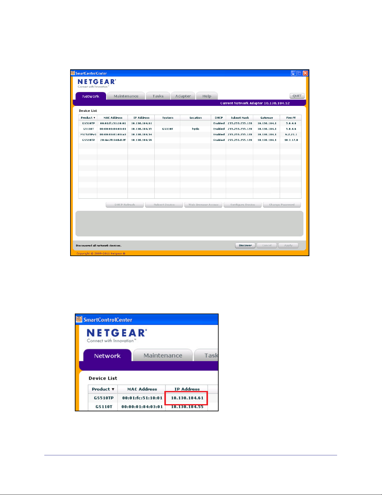
5. Click Discover for the Smart Control Center to find your switch. You should see a screen
similar to the one shown in Figure 1, Smart Switch Discovery.
Figure 1. Smart Switch Discovery
6. Make a note of the displayed IP address assigned by the DHCP server. You will need this
value to access the switch directly from a Web browser (without using the Smart Control
Center).
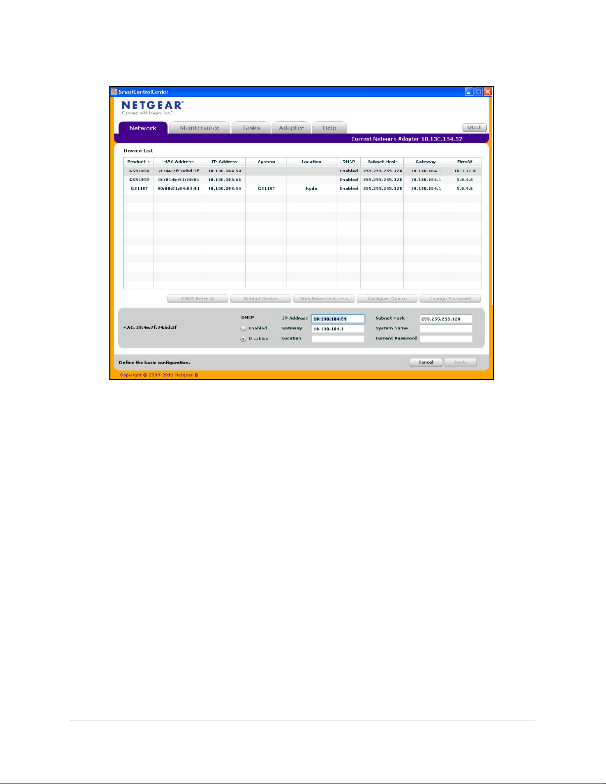
7. Select your switch by clicking the line that displays the switch, then click the
Web Browser Access button. The Smart Control Center displays a login window similar to
the following figure.
Getting Started
11
GS510TP and GS110T Gigabit Smart Switches
Use your Web browser to manage your switch. The default password is password. Then
use this page to proceed to management of the switch covered in Using the Web
Interface on page 22.
Switch Discovery in a Network without a DHCP Server
This section describes how to use the Smart Control Center to set up your switch in a
network without a DHCP server. If your network has no DHCP service, you must assign a
static IP address to your switch. If you choose, you can assign it a static IP address, even if
your network has DHCP service.
To assign a static IP address:
1. Connect the switch to your existing network.
2. Power on the switch by plugging in the AC-DC power adapter.
3. Install the Smart Control Center on your computer.
4. Start the Smart Control Center.
5. Click Discover for the Smart Control Center to find your GS110T or GS510TP switch. The
utility broadcasts Layer 2 discovery packets within the broadcast domain to discover the
switch.You should see a screen similar to Figure 1 on page 11.
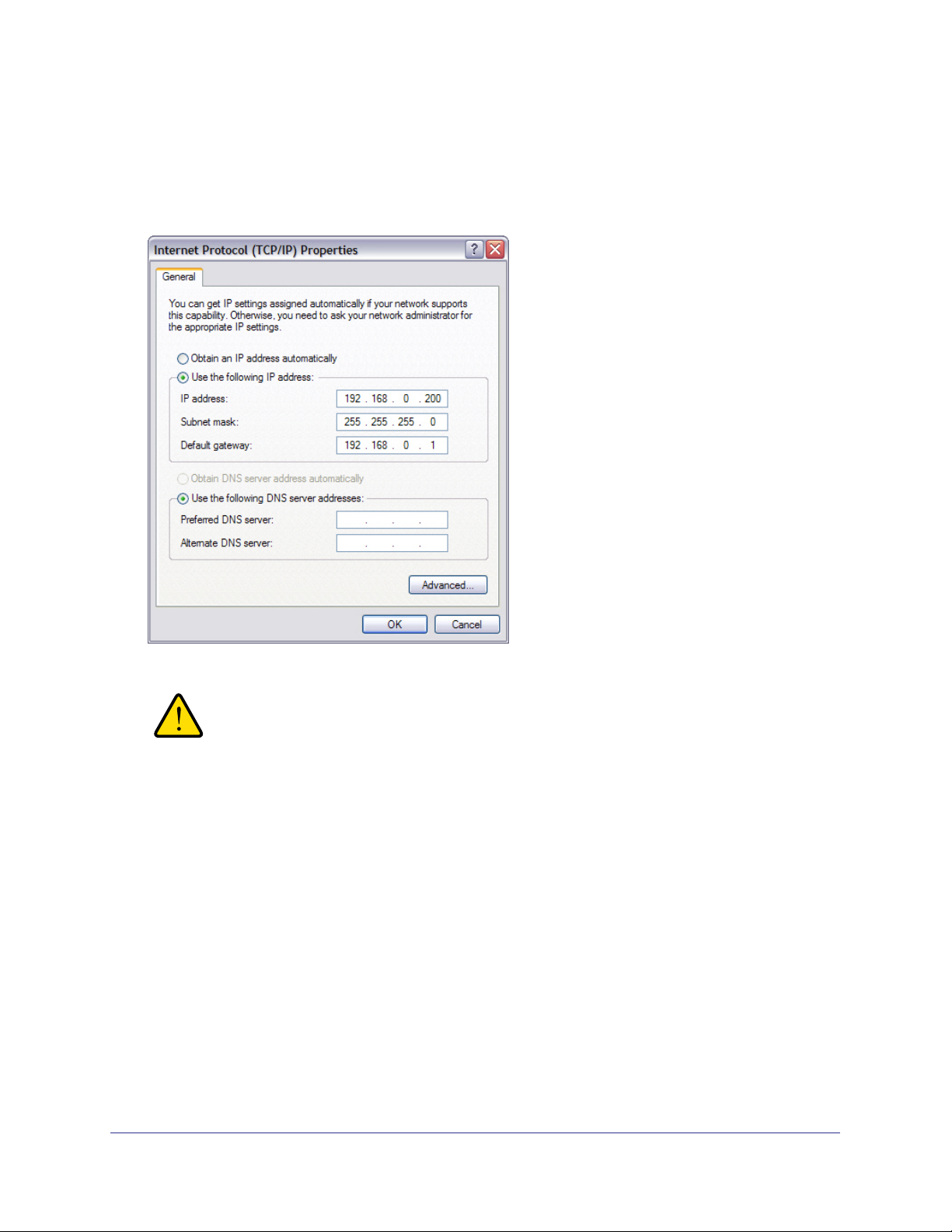
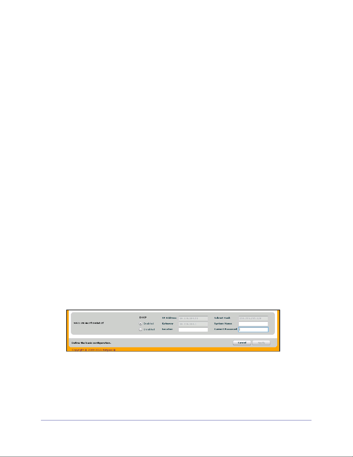
6. Select the switch, then click Configure Device. The page expands to display additional
fields at the bottom of the page, as the following figure shows.
Getting Started
12
GS510TP and GS110T Gigabit Smart Switches
7. Choose the Disabled radio box to disable DHCP.
8. Enter the static switch IP address, gateway IP address and subnet mask, and then type your
password and click Apply.
Tip: You must enter the current password every time you use the Smart
Control Center to update the switch setting. The default password is
password.
Please ensure that your PC and the switch are in the same subnet. Make a note of these
settings for later use.
Configuring the Network Settings on the Administrative System
If you choose not to use the Smart Control Center to configure the network information on the
switch, you can connect directly to the switch from an administrative system, such as a PC or
laptop computer. The IP address of the administrative system must be in the same subnet as
the default IP address on the switch. For most networks, this means you must change the IP
address of the administrative system to be on the same subnet as the default IP address of
the switch (192.168.0.239).
Getting Started
13
GS510TP and GS110T Gigabit Smart Switches
To change the IP address on an administrative system running a Microsoft® Windows®
operating system, open the Internet Protocol (TCP/IP) properties screen that you access
from the Local Area Connection properties, as shown in the following figure. You need
Windows Administrator privileges to change these settings.
WARNING:
When you change the IP address of your administrative system,
you will loose your connection to the rest of the network. Be sure
to write down your current network address settings before you
change them.
To modify the network settings on your administrative system:
1. On your PC, access the MS Windows operating system TCP/IP Properties.
2. Set the IP address of the administrative system to an address in the 192.168.0.0 network,
such as 192.168.0.200. The IP address must be different from that of the switch but within
the same subnet.
3. Click OK.
To configure a static address on the switch:
1. Use a straight-through cable to connect the Ethernet port on the administrative system
directly to any port on the GS110T or GS510TP.
Getting Started
14
GS510TP and GS110T Gigabit Smart Switches
2. Open a Web browser on your PC and connect to the management interface as described in
Web Access on page 15.
3. Change the network settings on the switch to match those of your network (this procedure is
described in IP Configuration on page 30).
After you change the network settings on the switch, return the network configuration on your
administrative system to the original settings.
Web Access
To access the GS110T or GS510TP management interface, use one of the following
methods:
• From the Smart Control Center, select the switch and click Web Browser Access.
• Open a Web browser and enter the IP address of the switch in the address field.
You must be able to ping the IP address of the GS110T or GS510TP management interface
from your administrative system for Web access to be available. If you used the Smart
Control Center to set up the IP address and subnet mask, either with or without a DHCP
server, use that IP address in the address field of your Web browser. If you did not change
the IP address of the switch from the default value, enter 192.168.0.239 into the address
field.
Clicking Web Browser Access on the Smart Control Center or accessing the switch directly
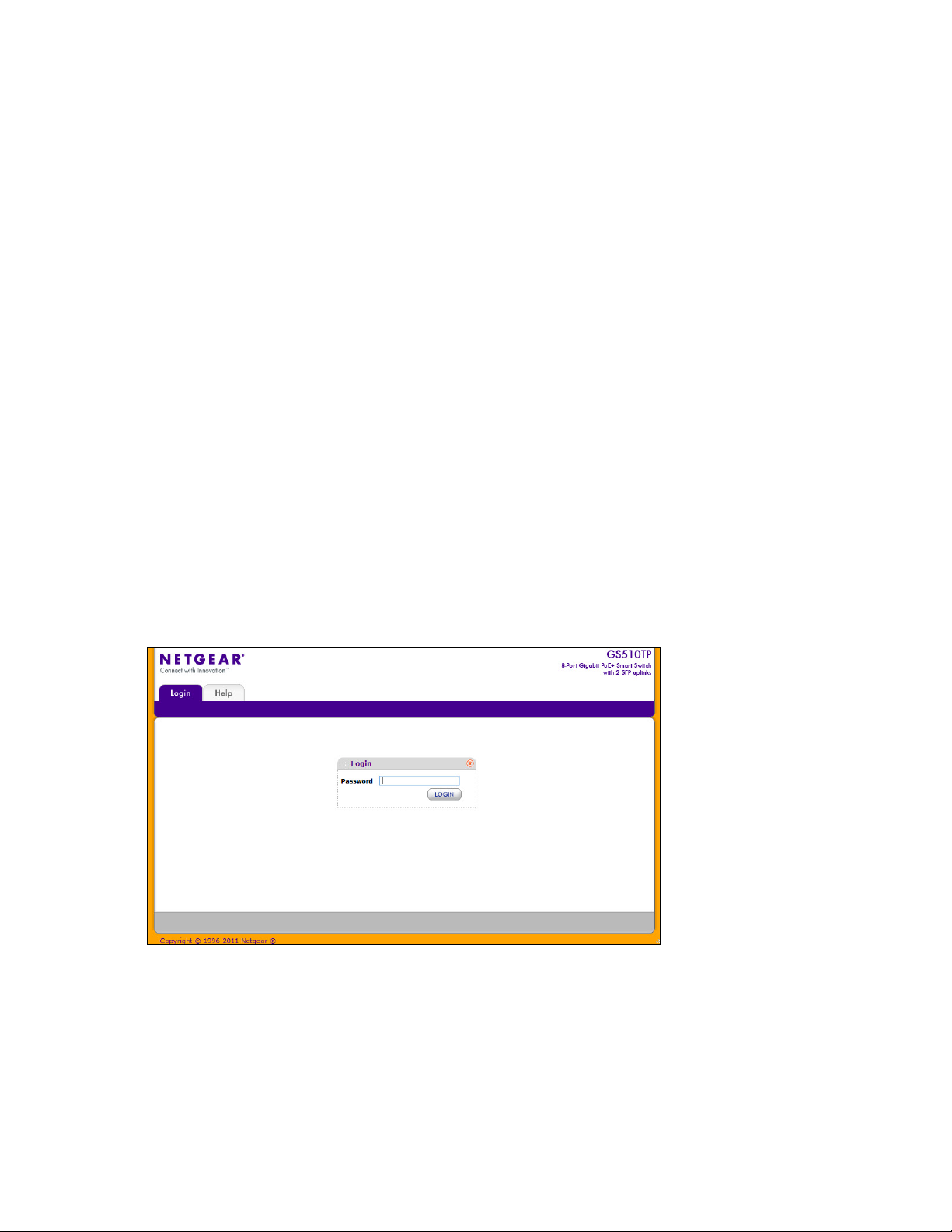
from your Web browser displays the login screen shown in the following figure.
Figure 2. Login Screen
Getting Started
15
GS510TP and GS110T Gigabit Smart Switches
Smart Control Center Utilities
In addition to device discovery and network address assignment, the Smart Control Center
includes several maintenance features. This section describes the following Smart Control
Center utilities:
• Network Utilities on page 16
• Configuration Upload and Download on page 17
• Firmware Upgrade on page 19
• Viewing and Managing Tasks on page 20
Network Utilities
From the Network tab, you can perform the following functions:
• DHCP Refresh—Forces the switch to release the current bindings and request new
address information from the DHCP server.
• Reboot Device—Reboots the selected device.
• Web Browser Access—Launches a Web browser and connects to the management
interface for the selected device.
• Configure Device—Allows you to modify network information for the switch, including
the IP address, DHCP client mode, system name, and location. For more information
about this feature, see Configuring the Device .
• Change Password—Allows you to set a new password for the device. For more
information about this feature, see Changing the Switch Password .
Configuring the Device
To modify switch information:
1. Select the switch.
2. Click Configure Device. Additional fields appear on the screen.
3. To assign or update a static IP address, default gateway, or subnet mask, disable the DHCP
client and enter the new information. You can also specify a system name and location for
the switch.
4. Type the password in the Current Password field. You cannot apply the changes without a
valid switch password. The default password for the switch is password.
5. Click Apply to update the switch with the changes to the network information.
Getting Started
16
GS510TP and GS110T Gigabit Smart Switches
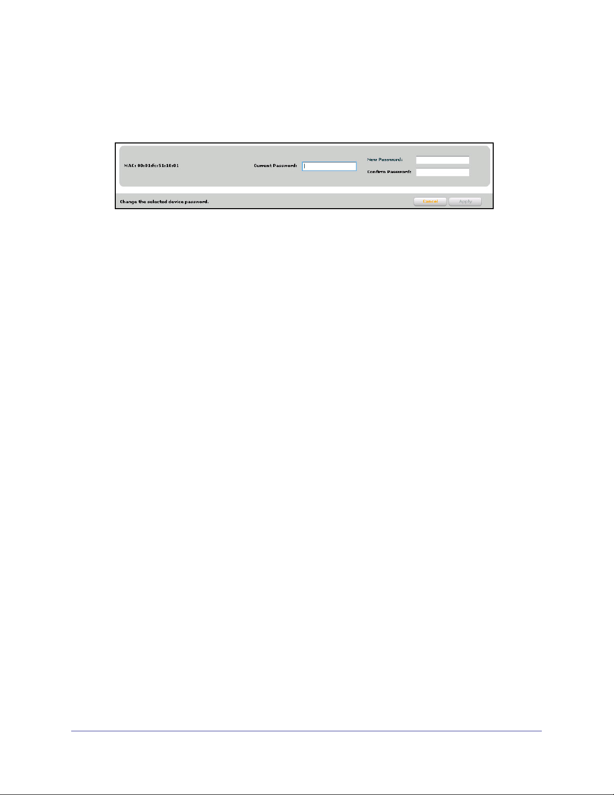
Changing the Switch Password
1. Select the switch.
2. Click Change Password. Additional fields appear on the screen.
3. Type the switch password in the Current Password field. The default password for the
switch is password.
4. Type the new password in the New Password and Confirm Password fields. The
password can contain up to 20 ASCII characters.
5. Click Apply to update the switch with the new password.
Configuration Upload and Download
When you make changes to the switch, the configuration information is stored in a file on the
switch. You can backup the configuration by uploading the configuration file from the switch
to an administrative system. You can download a saved configuration file from the
administrative system to the switch. The configuration file you download to the switch
overwrites the running configuration on the switch.
Configuration upload and download is useful if you want to save a copy of the current switch
configuration (Upload Configuration) before you make changes. If you do not like the
changes, you can use the Download Configuration option to restore the switch to the settings
in the saved configuration file.
To save a copy of the current switch configuration on your administrative system:
1. Click the Maintenance tab and select the device with the configuration to save.
2. Click Upload Configuration.
3. From the Browse for Folder window that appears, navigate to and select the folder where
you want to store the configuration file.
Getting Started
17

GS510TP and GS110T Gigabit Smart Switches
4. Click OK.
5. Enter the switch password and click Apply.
The file is uploaded to the administrative computer as a *.cfg file. You can open it and
view the contents with a text editor.
To restore the configuration to a previously saved version:
1. Click the Maintenance tab and select the device with the configuration to restore.
2. Click Download Configuration.
3. From the Select a Configuration window that appears, navigate to and select the
configuration file to download to the switch.
4. Click Open.
5. Enter the switch password and click Apply to begin the download process.
Optionally, you can schedule a different date and time to download the configuration file.
To delay the download process, clear the Run Now? check box and enter a date and
time to complete the download.
Note: Click the Tasks tab to view status information about the
configuration download.
Getting Started
18
GS510TP and GS110T Gigabit Smart Switches
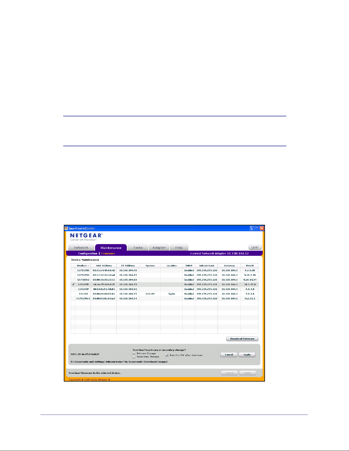
Firmware Upgrade
The application software for the GS510TP and GS110T Smart Switches is upgradeable,
enabling your switch to take advantage of improvements and additional features as they
become available. The upgrade procedure and the required equipment are described in this
section. This procedure assumes that you have downloaded or otherwise obtained the
firmware upgrade and that you have it available as a binary file on your computer. This
procedure uses the TFTP protocol to implement the transfer from computer to switch.
Note: You can also upgrade the firmware using the TFTP Download and
HTTP Download features mentioned in this book. See Download
File To Switch on page 206.
To upgrade your firmware:
1. Click the Maintenance tab, and then click the Firmware link directly below the tabs (see
Figure 1 on page 11).
2. Select the switch to upgrade and click Download Firmware.
3. From the Select new firmware window that appears, navigate to and select the firmware
image to download to the switch.
4. Click Open.
Getting Started
19

GS510TP and GS110T Gigabit Smart Switches
By default, the firmware is downloaded to primary storage and will be become the active
image after the download completes and the switch reboots. To download firmware to use
as a backup image, select the Secondary Storage option. To prevent the switch from
using the downloaded firmware as the active image, make sure the Run this FW after
download option is clear.
Note: NETGEAR recommends that you download the same image as the
primary and secondary image for redundancy.
5. Click Apply.
6. Enter the switch password to continue downloading the firmware.
Optionally, you can schedule a different date and time to download and install the
firmware image. To delay the upgrade process, clear the Run Now? check box and enter
a date and time to complete the upgrade.
7. Click Apply to download the firmware and upgrade the switch with the new image.
8. When the process is complete, the switch automatically reboots.
Note: Click the Tasks tab to view status information about the firmware
upgrade.
WARNING:
It is important that you do not power-off the administrative system
or the switch while the firmware upgrade is in progress.
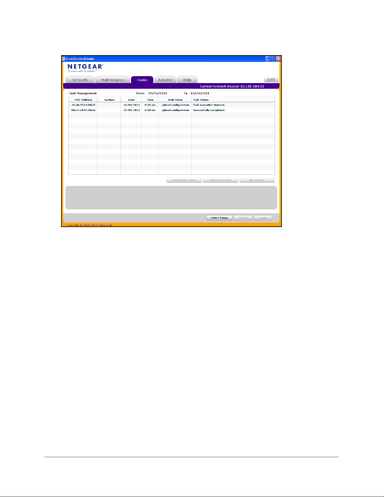
Viewing and Managing Tasks
From the Tasks tab, you can view information about configuration downloads and firmware
upgrades that have already occurred, are in progress, or are scheduled to take place at a
later time. You can also delete or reschedule selected tasks. The following figure shows the
Tasks page.
Getting Started
20
GS510TP and GS110T Gigabit Smart Switches
The following list describes the command buttons that are specific to the Tasks page:
• Delete Task—Remove a completed or schedule task from the list.
• Reschedule—Change the scheduled date and time for a pending firmware upgrade or
configuration download.
• Select Range—Select all tasks that occurred or are scheduled to occur within a certain
period of time.
Understanding the User Interfaces
The GS510TP and GS110T switch software includes a set of comprehensive management
functions for configuring and monitoring the system by using one of the following methods:
• Web user interface
• Simple Network Management Protocol (SNMP)
Each of the standards-based management methods allows you to configure and monitor the
components of the GS510TP and GS110T switch software. The method you use to manage
the system depends on your network size and requirements, and on your preference.
The GS510TP and GS110T Smart Switch Software Administration Manual describes how to
use the Web-based interface to manage and monitor the system.
Getting Started
21
GS510TP and GS110T Gigabit Smart Switches
Using the Web Interface
To access the switch by using a Web browser, the browser must meet the following software
requirements:
• HTML version 4.0, or later
• HTTP version 1.1, or later
• Java Runtime Environment 1.6 or later
Use the following procedures to log on to the Web interface:
1. Open a Web browser and enter the IP address of the switch in the Web browser
address field.
2. The factory default password is password. Type the password into the field on the login
screen, as shown in Figure 2 on page 15, and then click Login. Passwords are case
sensitive.
3. After the system authenticates you, the System Information page displays.
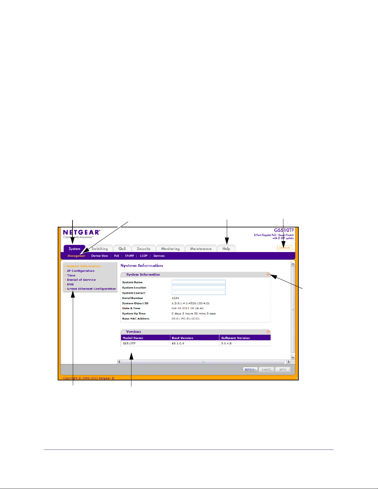
Figure 3 on page 22 shows the layout of the Smart Switch Web interface.
Navigation Tab Feature Link Logout Button
Page Menu
Configuration Status and Options
Help LInk
Help
Page
Figure 3. Administrative Page Layout
Getting Started
22
GS510TP and GS110T Gigabit Smart Switches
Navigation Tabs, Feature Links, and Page Menu
The navigation tabs along the top of the Web interface give you quick access to the various
switch functions. The tabs are always available and remain constant, regardless of which
feature you configure.
When you select a tab, the features for that tab appear as links directly under the tabs. The
feature links in the blue bar change according to the navigation tab that is selected.
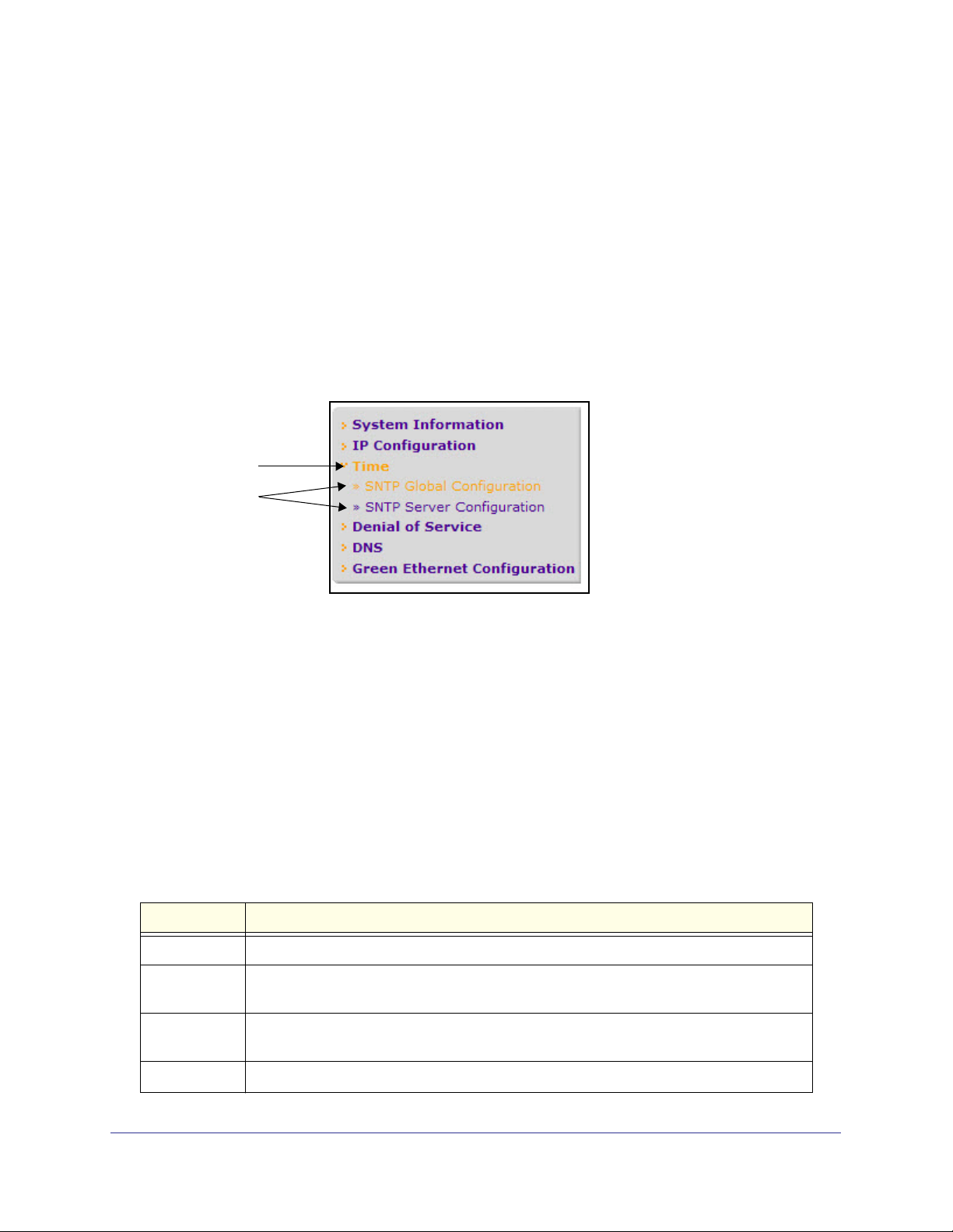
The configuration pages for each feature are available as links in the page menu on the left
side of the page. Some items in the menu expand to reveal multiple configuration pages, as
Figure 4 on page 23. shows. When you click a menu item that includes multiple configuration
pages, the item becomes preceded by a down arrow symbol and expands to display the
additional pages.
Page Link
Configuration
Pages
Figure 4. Menu Hierarchy
Configuration and Monitoring Options
The area directly under the feature links and to the right of the page menu displays the
configuration information or status for the page you select. On pages that contain
configuration options, you can input information into fields or select options from drop-down
menus.
Each page contains access to the HTML-based help that explains the fields and
configuration options for the page. Each page also contains command buttons.
The following table shows the command buttons that are used throughout the pages in the
Web interface:
Table 1. Common Command Buttons
Button Function
Add Clicking Add adds the new item configured in the heading row of a table.
Apply Clicking the Apply button sends the updated configuration to the switch. Configuration
changes take effect immediately.
Cancel Clicking Cancel cancels the configuration on the screen and resets the data on the screen
to the latest value of the switch.
Delete Clicking Delete removes the selected item.
Getting Started
23
GS510TP and GS110T Gigabit Smart Switches
Table 1. Common Command Buttons (continued)
Button Function
Refresh Clicking the Refresh button refreshes the page with the latest information from the device.
Logout Clicking the Logout button ends the session.
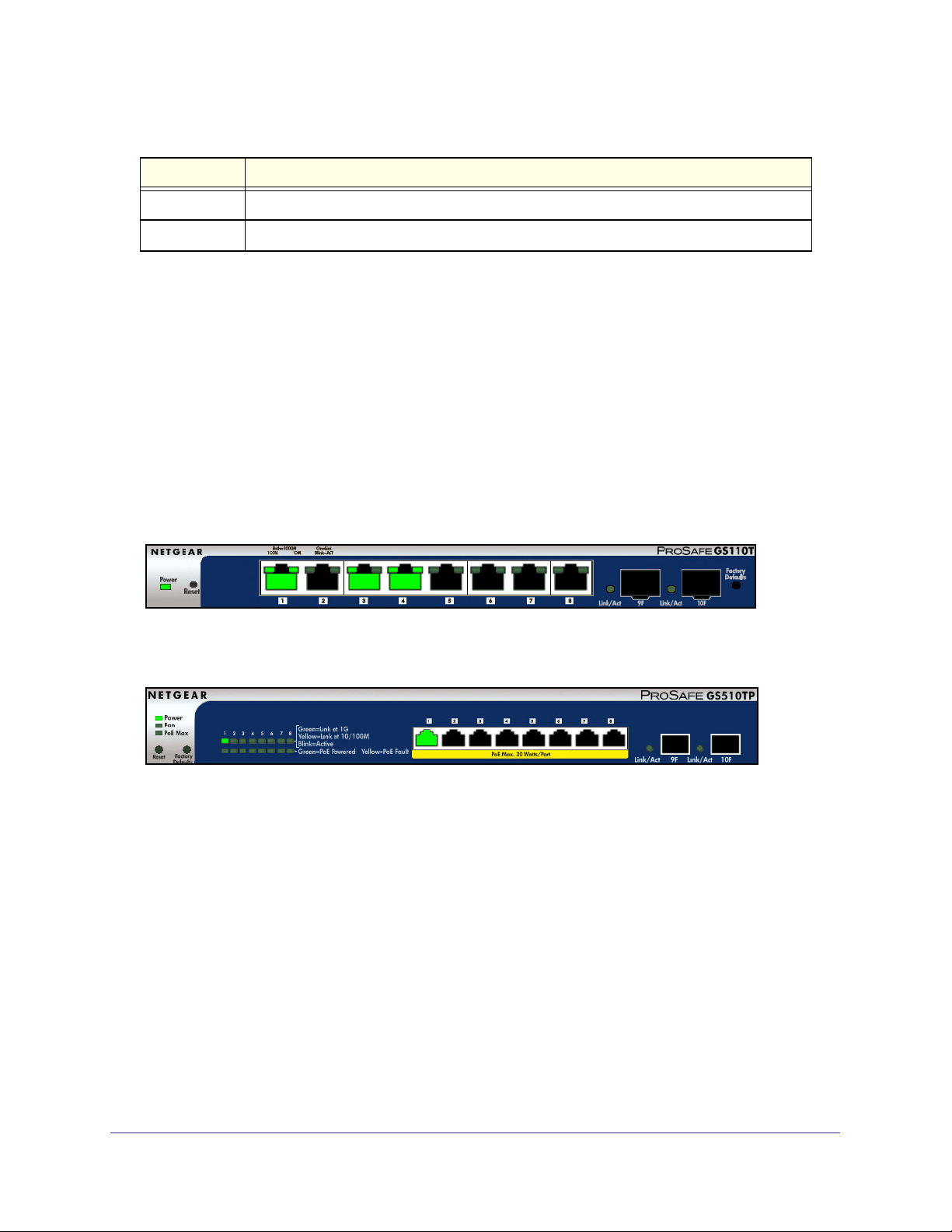
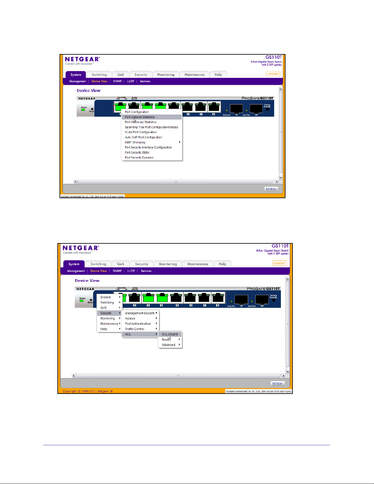
Device View
The Device View is a Java® applet that displays the ports on the switch. This graphic provides
an alternate way to navigate to configuration and monitoring options. The graphic also
provides information about device ports, current configuration and status, table information,
and feature components.
The Device View is available from the System> Device View page.
The port coloring indicates whether a port is currently active. Green indicates that the port is
enabled, red indicates that an error has occurred on the port, or red indicates that the link is
disabled.
The following figure shows the Device View of the GS110T.
The following figure shows the Device View of the GS510TP.
Click the port you want to view or configure to see a menu that displays statistics and
configuration options. Click the menu option to access the page that contains the
configuration or monitoring options.
Getting Started
24
GS510TP and GS110T Gigabit Smart Switches
If you click the graphic, but do not click a specific port, the main menu appears, as the
following figure shows. This menu contains the same option as the navigation tabs at the top
of the page.
Getting Started
25

GS510TP and GS110T Gigabit Smart Switches
Help Page Access
Every page contains a link to the online help , which contains information to assist in
configuring and managing the switch. The online help pages are context sensitive. For
example, if the IP Addressing page is open, the help topic for that page displays if you click
Help. Figure 3 on page 22 shows the location of the link to the Help Page on the Web
interface.
User-Defined Fields
User-defined fields can contain 1 to 159 characters, unless otherwise noted on the
configuration Web page. All characters may be used except for the following (unless
specifically noted in for that feature):
\ <
/ >|
* |
?
Using SNMP
The GS510TP and GS110T switch software supports the configuration of SNMP groups and
users that can manage traps that the SNMP agent generates. GS510TP and GS110T
switches use both standard public MIBs for standard functionality and private MIBs that
support additional switch functionality. All private MIBs begin with a “-” prefix. The main object
for interface configuration is in -SWITCHING-MIB, which is a private MIB. Some interface
configurations also involve objects in the public MIB, IF-MIB.
SNMP is enabled by default. The System > Management > System Information Web page,
which is the page that displays after a successful login, displays the information you need to
configure an SNMP manager to access the switch.
Any user can connect to the switch using the SNMPv3 protocol, but for authentication and
encryption, the switch supports only one user which is admin; therefore there is only one
profile that can be created or modified.
To configure authentication and encryption settings for the SNMPv3 admin profile by using
the Web interface:
1. Navigate to the System > SNMP > SNMPv3 > User Configuration page.
2. To enable authentication, select an Authentication Protocol option, which is either MD5 or
SHA.
3. To enable encryption, select the DES option in the Encryption Protocol field. Then, enter
an encryption code of eight or more alphanumeric characters in the Encryption Key field.
4. Click Apply.
Getting Started
26

GS510TP and GS110T Gigabit Smart Switches
To access configuration information for SNMPv1 or SNMPv2, click System > SNMP >
SNMPv1/v2 and click the page that contains the information to configure.
Interface Naming Convention
The GS510TP and GS110T switch software supports physical and logical interfaces.
Interfaces are identified by their type and the interface number. The physical ports are gigabit
interfaces and are numbered on the front panel. You configure the logical interfaces by using
the software. The following table describes the naming convention for all interfaces available
on the switch.
Table 2. Interface Naming Conventions
Interface Description Example
Physical The physical ports are gigabit Ethernet
interfaces and are numbered sequentially
starting from one.
Link Aggregation Group (LAG) LAG interfaces are logical interfaces that are
only used for bridging functions.
CPU Management Interface This is the internal switch interface responsible
for the switch base MAC address. This interface
is not configurable and is always listed in the
MAC Address Table.
g1, g2, g3
l1, l2, l3
LAG1, LAG2
c1
Getting Started
27

2. Configuring System Information
Use the features in the System tab to define the switch’s relationship to its environment. The
System tab contains links to the following features:
• Management on page 28
• PoE/PoE+ (GS510TP Only) on page 42
• SNMP on page 48
• LLDP on page 53
• Services — DHCP Filtering on page 64
Management
This section describes how to display the switch status and specify some basic switch
information, such as the management interface IP address, system clock settings, and DNS
information. From the Management link, you can access the following pages:
2
• System Information on page 28
• IP Configuration on page 30
• Time on page 31
• Denial of Service on page 37
• DNS on page 39
• Green Ethernet Configuration on page 42
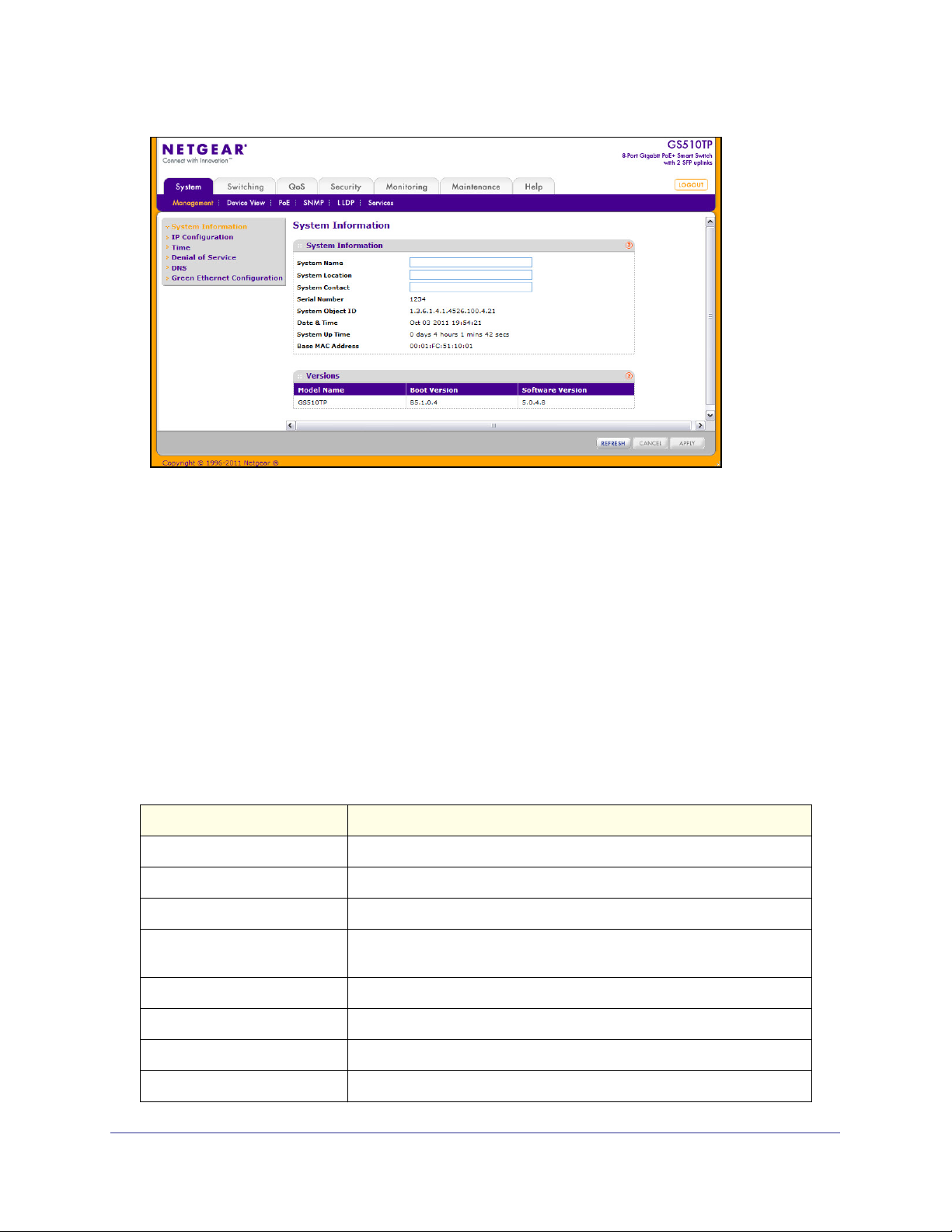
System Information
After a successful login, the System Information page displays. Use this page to configure
and view general device information.
To display the System Information page, click System > Management > System Information.
A screen similar to the following displays.
28
GS510TP and GS110T Gigabit Smart Switches
To define system information:
1. Open the System Information page.
2. Define the following fields:
• System Name. Enter the name you want to use to identify this switch. You may use
up to 31 alphanumeric characters. The factory default is blank.
• System Location. Enter the location of this switch. You may use up to 31
alphanumeric characters. The factory default is blank.
• System Contact. Enter the contact person for this switch. You may use up to 31
alphanumeric characters. The factory default is blank.
3. Click Apply.
The system parameters are applied, and the device is updated.
The following table describes the status information the System Page displays.
Field Description
Serial Number The serial number of the switch.
System Object ID The base object ID for the switch's enterprise MIB.
Date & Time The current date and time.
System Up Time Displays the number of days, hours, and minutes since the last system
restart.
Base MAC Address The universally assigned network address.
Model Name The model name of the switch.
Boot Version The boot code version of the switch.
Software Version The software version of the switch.
Configuring System Information
29
GS510TP and GS110T Gigabit Smart Switches
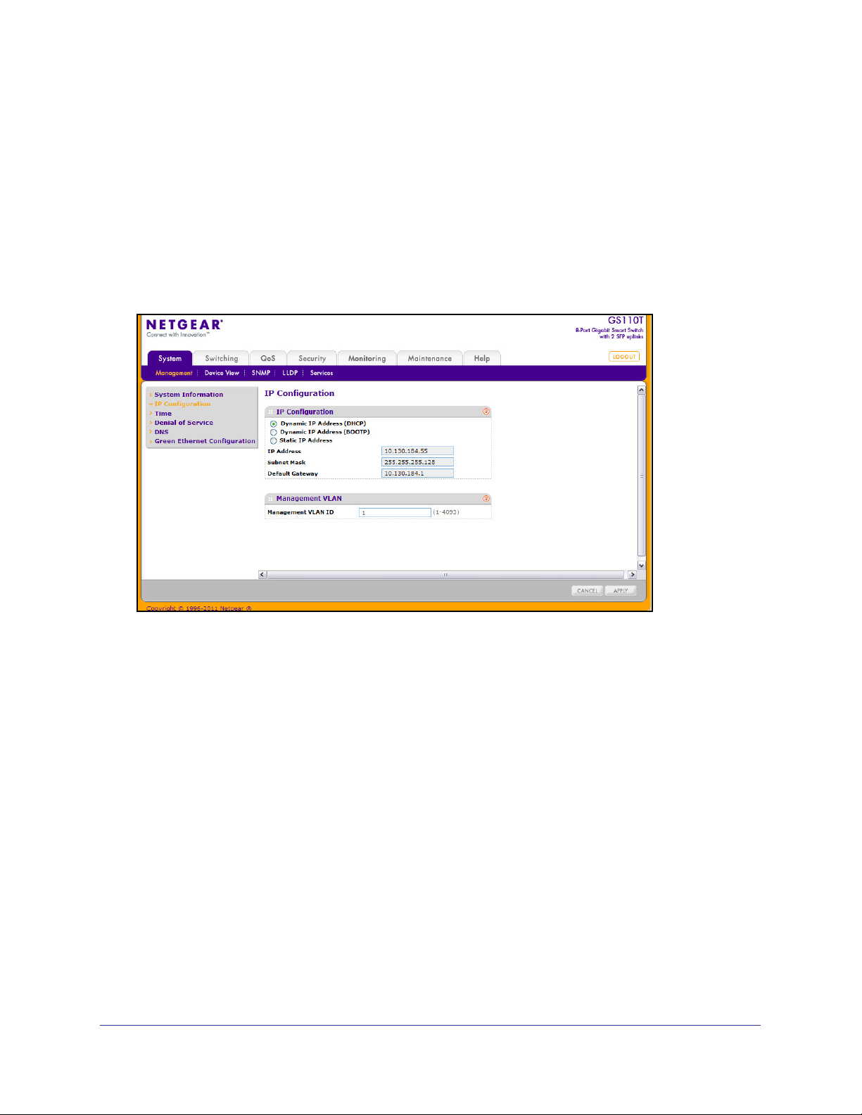
IP Configuration
Use the IP Configuration page to configure network information for the management
interface, which is the logical interface used for in-band connectivity with the switch through
any of the switch's front panel ports. The configuration parameters associated with the
switch's network interface do not affect the configuration of the front panel ports through
which traffic is switched or routed.
To access the page, click System > Management > IP Configuration. A screen similar to the
following displays.
To configure the network information for the management interface:
1. Select the appropriate radio button to determine how to configure the network
information for the switch management interface:
• Dynamic IP Address (DHCP). Specifies that the switch must obtain the IP address
through a DHCP server.
• Dynamic IP Address (BOOTP). Specifies that the switch must obtain the IP address
through a BootP server.
• Static IP Address. Specifies that the IP address, subnet mask, and default gateway
must be manually configured. Enter this information in the fields below this radio
button.
2. If you selected the Static IP Address option, configure the following network information:
• IP Address. The IP address of the network interface. The factory default value is
192.168.0.239. Each part of the IP address must start with a number other than zero.
For example, IP addresses 001.100.192.6 and 192.001.10.3 are not valid.
• Subnet Mask. The IP subnet mask for the interface. The factory default value is
255.255.255.0.
• Default Gateway. The default gateway for the IP interface. The factory default value
is 192.168.0.254.
Configuring System Information
30

GS510TP and GS110T Gigabit Smart Switches
3. Specify the VLAN ID for the management VLAN.
The management VLAN is used to establish an IP connection to the switch from a
workstation that is connected to a port in the same VLAN. If not specified, the active
management VLAN ID is 1 (default), which allows an IP connection to be established
through any port.
When the management VLAN is set to a different value, an IP connection can be made
only through a port that is part of the management VLAN. It is also mandatory that the
port VLAN ID (PVID) of the port to be connected in that management VLAN be the same
as the management VLAN ID.
The management VLAN has the following requirements:
• Only one management VLAN can be active at a time.
• When a new management VLAN is configured, connectivity through the existing
management VLAN is lost.
• The management station should be reconnected to the port in the new management
VLAN.
Note: Make sure that the VLAN to be configured as the management
VLAN exists. And make sure that the PVID of at least one port that is
a port of the VLAN is the same as the management VLAN ID. For
information about creating VLANs and configuring the PVID for a
port, see VLANs on page 75.
4. If you change any of the network connection parameters, click Apply to apply the changes
to the system.
5. Click Cancel to cancel the configuration on the screen and reset the data on the screen to
the latest value of the switch.
Time
The GS510TP and GS110T switch software supports the Simple Network Time Protocol
(SNTP). You can also set the system time manually
SNTP assures accurate network device clock time synchronization up to the millisecond.
Time synchronization is performed by a network SNTP server. The GS510TP and GS110T
switch software operates only as an SNTP client and cannot provide time services to other
systems.
Time sources are established by Stratums. Stratums define the accuracy of the reference
clock. The higher the stratum (where zero is the highest), the more accurate the clock. The
device receives time from stratum 1 and above since it is itself a stratum 2 device.
The following is an example of stratums:
• Stratum 0: A real-time clock is used as the time source, for example, a GPS system.
Configuring System Information
31

GS510TP and GS110T Gigabit Smart Switches
• Stratum 1: A server that is directly linked to a Stratum 0 time source is used. Stratum 1
time servers provide primary network time standards.
• Stratum 2: The time source is distanced from the Stratum 1 server over a network path.
For example, a Stratum 2 server receives the time over a network link, via NTP, from a
Stratum 1 server.
Information received from SNTP servers is evaluated based on the time level and server
type.
SNTP time definitions are assessed and determined by the following time levels:
• T1: Time at which the original request was sent by the client.
• T2: Time at which the original request was received by the server.
• T3: Time at which the server sent a reply.
• T4: Time at which the client received the server's reply.
The device can poll Unicast server types for the server time.
Polling for Unicast information is used for polling a server for which the IP address is known.
SNTP servers that have been configured on the device are the only ones that are polled for
synchronization information. T1 through T4 are used to determine server time. This is the
preferred method for synchronizing device time because it is the most secure method. If this
method is selected, SNTP information is accepted only from SNTP servers defined on the
device using the SNTP Server Configuration page.
The device retrieves synchronization information, either by actively requesting information or
at every poll interval.
Time Configuration
Use the Time Configuration page to view and adjust date and time settings.
To display the Time Configuration page, click System > Management > Time > SNTP Global
Configuration.
Configuring System Information
32

GS510TP and GS110T Gigabit Smart Switches
To configure the time by using the CPU clock cycle as the source:
1. From the Clock Source field, select Local.
2. In the Date field, enter the date in the DD/MM/YYYY format.
3. In the Time field, enter the time in HH:MM:SS format.
Note: If you do not enter a date and time, the switch will calculate the date
and time using the CPU’s clock cycle.
When the Clock Source is set to Local, the Time Zone field is grayed out (disabled):
4. Click Apply to send the updated configuration to the switch. Configuration changes occur
immediately.
To configure the time through SNTP:
1. From the Clock Source field, select SNTP.
When the Clock Source is set to SNTP, the Date and Time fields are grayed out
(disabled). The switch gets the date and time from the network.
2. Use the menu to select the Coordinated Universal Time (UTC) time zone in which the switch
is located, expressed as the number of hours. The options in the Time Zone menu specify
the time difference from UTC time zone.
3. Click Apply to send the updated configuration to the switch. Configuration changes take
effect immediately.
Configuring System Information
33

GS510TP and GS110T Gigabit Smart Switches
4. Use the SNTP Server Configuration page to configure the SNTP server settings, as
described in
SNTP Server Configuration on page 35.
5. Click Refresh to refresh the page with the most current data from the switch.
6. Click Cancel to cancel the configuration on the screen and reset the data on the screen to
the latest value of the switch.
The SNTP Global Status table on the Time Configuration page displays information about
the system’s SNTP client. The following table describes the SNTP Global Status fields.
Field Description
Version Specifies the SNTP Version the client supports.
Supported Mode Specifies the SNTP modes the client supports. Multiple modes may be
supported by a client.
Last Update Time Specifies the local date and time (UTC) the SNTP client last updated the system
clock.
Last Attempt Time Specifies the local date and time (UTC) of the last SNTP request or receipt of an
unsolicited message.
Last Attempt Status Specifies the status of the last SNTP request or unsolicited message for both
unicast mode. If no message has been received from a server, a status of Other
is displayed. These values are appropriate for all operational modes:
• Other: None of the following enumeration values.
• Success: The SNTP operation was successful and the system time was
updated.
• Request Timed Out: A directed SNTP request timed out without receiving a
response from the SNTP server.
• Bad Date Encoded: The time provided by the SNTP server is not valid.
• Version Not Supported: The SNTP version supported by the server is not
compatible with the version supported by the client.
• Server Unsynchronized: The SNTP server is not synchronized with its
peers. This is indicated via the 'leap indicator' field on the SNTP message.
• Server Kiss Of Death: The SNTP server indicated that no further queries
were to be sent to this server. This is indicated by a stratum field equal to 0 in
a message received from a server.
Server IP Address Specifies the IP address of the server for the last received valid packet. If no
message has been received from any server, an empty string is shown.
Address Type Specifies the address type of the SNTP Server address for the last received
valid packet.
Server Stratum Specifies the claimed stratum of the server for the last received valid packet.
Reference Clock Id Specifies the reference clock identifier of the server for the last received valid
packet.
Server Mode Specifies the mode of the server for the last received valid packet.
Configuring System Information
34

GS510TP and GS110T Gigabit Smart Switches
Field Description
Unicast Sever Max
Entries
Unicast Server Current
Entries
Specifies the maximum number of unicast server entries that can be configured
on this client.
Specifies the number of current valid unicast server entries configured for this
client.
Click Refresh to refresh the page with the most current data from the switch.
SNTP Server Configuration
Use the SNTP Server Configuration page to view and modify information for adding and
modifying Simple Network Time Protocol SNTP servers.
To display the SNTP Server Configuration page, click System > Management > Time > SNTP
Server Configuration.
To configure a new SNTP Server:
1. Enter the appropriate SNTP server information in the available fields:
• Server Type. Specifies whether the address for the SNTP server is an IP address
(IPv4) or hostname (DNS).
• Address. Enter the IP address or the hostname of the SNTP server.
• Port. Enter a port number on the SNTP server to which SNTP requests are sent. The
valid range is 1–65535. The default is 123.
• Priority . Specifies the priority of this server entry in determining the sequence of
servers to which SNTP requests are sent. Enter a priority from 1–3, with 1 being the
default and the highest priority. Servers with lowest numbers have priority.
• Version. Enter the protocol version number. The range is 1–4.
2. Click Add.
Configuring System Information
35

GS510TP and GS110T Gigabit Smart Switches
3. Repeat the previous steps to add additional SNTP servers. You can configure up to three
SNTP servers.
4. To removing an SNTP server, select the check box next to the configured server to remove,
and then click Delete. The entry is removed, and the device is updated.
5. To change the settings for an existing SNTP server, select the check box next to the
configured server and enter new values in the available fields, and then click Apply.
Configuration changes take effect immediately.
6. Click Cancel to cancel the configuration on the screen and reset the data on the screen to
the latest value of the switch.
The SNTP Server Status table displays status information about the SNTP servers
configured on your switch. The following table describes the SNTP Global Status fields.
Field Description
Address Specifies all the existing Server Addresses. If no Server configuration exists,
a message saying “No SNTP server exists” flashes on the screen.
Last Update Time Specifies the local date and time (UTC) that the response from this server
was used to update the system clock.
Last Attempt Time Specifies the local date and time (UTC) that this SNTP server was last
queried.
Last Attempt Status Specifies the status of the last SNTP request to this server. If no packet has
been received from this server, a status of Other is displayed:
• Other: None of the following enumeration values.
• Success: The SNTP operation was successful and the system time was
updated.
• Request Timed Out: A directed SNTP request timed out without receiving
a response from the SNTP server.
• Bad Date Encoded: The time provided by the SNTP server is not valid.
• Version Not Supported: The SNTP version supported by the server is not
compatible with the version supported by the client.
• Server Unsynchronized: The SNTP server is not synchronized with its
peers. This is indicated via the 'leap indicator' field on the SNTP message.
• Server Kiss Of Death: The SNTP server indicated that no further queries
were to be sent to this server. This is indicated by a stratum field equal to
0 in a message received from a server.
Requests Specifies the number of SNTP requests made to this server since last agent
reboot.
Failed Requests Specifies the number of failed SNTP requests made to this server since last
reboot.
Click Refresh to refresh the page with the most current data from the switch.
Configuring System Information
36

GS510TP and GS110T Gigabit Smart Switches
Denial of Service
Use the Denial of Service (DoS) page to configure DoS control. The GS510TP and GS110T
switch software provides support for classifying and blocking specific types of DoS attacks.
You can configure your system to monitor and block six types of attacks:
• SIP=DIP: Source IP address = Destination IP address.
• First Fragment: TCP Header size is smaller than the configured value.
• TCP Fragment: IP Fragment Offset = 1.
• TCP Flag: TCP Flag SYN set and Source Port < 1024 or TCP Control Flags = 0 and TCP
Sequence Number = 0 or TCP Flags FIN, URG, and PSH set and TCP Sequence
Number = 0 or TCP Flags SYN and FIN set.
• L4 Port: Source TCP/UDP Port = Destination TCP/UDP Port.
• ICMP: Limiting the size of ICMP Ping packets.
Auto-DoS Configuration
The Auto-DoS Configuration page lets you automatically enable all the DoS features
available on the switch, except for the L4 Port attack. See the previous section for information
about the types of DoS attacks the switch can monitor and block.
Note: When Auto-DoS is enabled, a port that is under attack is
automatically shut down and does not forward traffic.
To access the Auto-DoS Configuration page, click System > Management > Denial of
Service > Auto-DoS Configuration.
To configure the Auto-DoS feature:
1. Select a radio button to enable or disable Auto-DoS:
• Disable. Auto-DoS is disabled (default).
• Enable. Auto-DoS is enabled.
Configuring System Information
37

GS510TP and GS110T Gigabit Smart Switches
2. Click Apply to send the updated configuration to the switch. Configuration changes occur
immediately.
3. Click Cancel to cancel the configuration on the screen and reset the data on the screen to
the latest value of the switch.
DoS Configuration
The DoS Configuration page lets you to select which types of DoS attacks for the switch to
monitor and block.
To access the DoS Configuration page, click System > Management > Denial of Service >
DoS Configuration.
To configure individual DoS settings:
1. Select the types of DoS attacks for the switch to monitor and block and configure any
associated values, as the following list describes.
• Denial of Service SIP=DIP. Enable or disable this option by selecting the appropriate
radio button. Enabling SIP=DIP DoS prevention causes the switch to drop packets
that have a source IP address equal to the destination IP address. The factory default
is Disable.
• Denial of Service First Fragment. Enable or disable this option by selecting the
appropriate radio button. Enabling First Fragment DoS prevention causes the switch
to drop packets that have a TCP header smaller than the configured Min TCP Hdr
Size. The factory default is Disable.
• Denial of Service Min TCP Hdr Size. Specify the Min TCP Hdr Size allowed. If First
Fragment DoS prevention is enabled, the switch will drop packets that have a TCP
header smaller than this configured Min TCP Hdr Size. The factory default is 20
bytes.
• Denial of Service TCP Fragment. Enable or disable this option by selecting the
appropriate radio button. Enabling TCP Fragment DoS prevention causes the switch
Configuring System Information
38

GS510TP and GS110T Gigabit Smart Switches
to drop packets that have an IP fragment offset equal to 1. The factory default is
Disable.
• Denial of Service TCP Flag. Enable or disable this option by selecting the
appropriate radio button. Enabling TCP Flag DoS prevention causes the switch to
drop packets that have TCP flag SYN set and TCP source port less than 1024 or TCP
control flags set to 0 and TCP sequence number set to 0 or TCP flags FIN, URG, and
PSH set and TCP sequence number set to 0 or both TCP flags SYN and FIN set. The
factory default is Disable.
• Denial of Service L4 Port. Enable or disable this option by selecting the appropriate
radio button. Enabling L4 Port DoS prevention causes the switch to drop packets that
have TCP/UDP source port equal to TCP/UDP destination port. The factory default is
Disable.
• Denial of Service ICMP. Enable or disable this option by selecting the appropriate
radio button. Enabling ICMP DoS prevention causes the switch to drop ICMP packets
that have a type set to ECHO_REQ (ping) and a size greater than the configured
ICMP packet size. The factory default is Disable.
• Denial of Service Max ICMP Size. Specify the Max ICMP packet size allowed. If
ICMP DoS prevention is enabled, the switch will drop ICMP ping packets that have a
size greater then this configured Max ICMP packet size. The factory default is
Disable.
2. If you change any of the DoS settings, click Apply to apply the changes to the switch.
3. Click Cancel to cancel the configuration on the screen and reset the data on the screen to
the latest value of the switch.
DNS
You can use these pages to configure information about DNS servers the network uses and
how the switch operates as a DNS client.
DNS Configuration
Use this page to configure global DNS settings and DNS server information.
To access this page, click System > Management > DNS > DNS Configuration.
Configuring System Information
39

GS510TP and GS110T Gigabit Smart Switches
To configure the global DNS settings
1. Specify whether to enable or disable the administrative status of the DNS Client.
• Enable. Allow the switch to send DNS queries to a DNS server to resolve a DNS
domain name.
• Disable. Prevent the switch from sending DNS queries.
2. Enter the DNS default domain name to include in DNS queries. When the system is
performing a lookup on an unqualified hostname, this field is provided as the domain name
(for example, if default domain name is netgear.com and the user enters test, then test is
changed to test.netgear.com to resolve the name).
3. To specify the DNS server to which the switch sends DNS queries, enter an IP address in
standard IPv4 dot notation in the DNS Server Address and click Add. The server appears
in the list below. You can specify up to eight DNS servers. The precedence is set in the order
created.
4. To remove a DNS server from the list, select the check box next to the server you want to
remove and click Delete. If no DNS server is specified, the check box is global and will
delete all the DNS servers listed.
5. Click Cancel to cancel the configuration on the screen and reset the data on the screen to
the latest value of the switch.
6. Click Apply to send the updated configuration to the switch. Configuration changes take
effect immediately.
Host Configuration
Use this page to manually map host names to IP addresses or to view dynamic DNS
mappings.
To access this page, click System > Management > DNS > Host Configuration.
Configuring System Information
40

GS510TP and GS110T Gigabit Smart Switches
To add a static entry to the local DNS table:
1. Specify the static host name to add. Enter up to 158 characters.
2. Specify the IP address in standard IPv4 dot notation to associate with the hostname.
3. Click Add. The entry appears in the list below.
4. To remove an entry from the static DNS table, select the check box next to the entry and
click Delete.
5. To change the hostname or IP address in an entry, select the check box next to the entry
and enter the new information in the appropriate field, and then click Apply.
6. Click Cancel to cancel the configuration on the screen and reset the data on the screen to
the latest value of the switch.
The Dynamic Host Configuration table shows host name-to-IP address entries that the switch
has learned. The following table describes the dynamic host fields:
Field Description
Host Lists the host name you assign to the specified IP address.
Total Amount of time since the dynamic entry was first added to the table.
Elapsed Amount of time since the dynamic entry was last updated.
Type The type of the dynamic entry.
Addresses Lists the IP address associated with the host name.
Click Refresh to refresh the table with the most current data from the switch.
Click Clear to delete Dynamic Host Entries. The table will be repopulated with entries as they
are learned.
Configuring System Information
41

GS510TP and GS110T Gigabit Smart Switches
Green Ethernet Configuration
Use this page to configure Green Ethernet features. Using the Green Ethernet features
allows for power consumption savings.
To access this page, click System > Management > Green Ethernet Configuration.
To configure the Green Ethernet feature:
1. Enable or disable the Auto Power-Down Mode.
• Enable. When the port link is down, the PHY automatically goes down for a short
period of time and then wake up to check link pulses. This behavior saves power
consumption when there is no link partner while still allowing the port to perform
auto-negotiation if a link partner does become present.
• Disable. The PHY remains up even if no link partner is present.
2. Enable or disable the Short Cable Mode.
• Enable. The switch performs a cable test on each cable connect to its ports. If the
cable is less than 10m in length, the port is placed in low power mode (nominal
power).
• Disable. Full transmit power is provided to all ports, regardless of cable length.
3. Click Apply to send the updated configuration to the switch. Configuration changes take
effect immediately.
PoE/PoE+ (GS510TP Only)
Ports g1–g8 on the GS510TP are PoE (IEEE 802.3af) and PoE+ (IEEE 802.3at) compliant
ports. Each port is capable of delivering up to 30W of reliable, uninterrupted power to
connected PoE-powered devices (PD). The GS510TP can provide a total of 130W of power
to all connected devices. You can configure per-port priority settings, timers, and power limits
to manage the power supplied to the connected PDs and to ensure that the GS510TP power
budget is used effectively.
From the PoE link under the System tab, you can view and configure PoE settings for the
switch and for ports g1–g8.
Configuring System Information
42

GS510TP and GS110T Gigabit Smart Switches
From the PoE link, you can access the following pages:
• PoE Configuration on page 43
• PoE Port Configuration on page 44
• Timer Global Configuration on page 46
• Timer Schedule Configuration on page 47
PoE Configuration
Use the PoE Configuration page to view global PoE power information and to configure PoE
SNMP trap settings.
To display the PoE Configuration page, click System > PoE > Basic > PoE Configuration.
Note: You can also access the PoE Configuration page by clicking System
> PoE > Advanced > PoE Configuration.
To configure PoE trap settings:
1. Select the appropriate radio button to enable or disable SNMP traps.
2. Click Apply to apply the new settings to the system.
3. Click Cancel to cancel the configuration on the screen and reset the data on the screen to
the latest value of the switch.
4. Click Refresh to update the screen with the current information.
The PoE Configuration page also provides the following information:
Field Description
Power Status Indicates whether the PoE capability is on or off.
Nominal Power Indicates the nominal amount of power the switch can provide to all ports.
Configuring System Information
43

GS510TP and GS110T Gigabit Smart Switches
Field Description
Threshold Power Shows the amount of power the system can consume before the system will
not provide power to an additional port.
Consumed Power
Shows the total amount of power currently being delivered to all ports.
PoE Port Configuration
Use the PoE Port Configuration page to configure per-port PoE settings.
To display the PoE Port Configuration page, click System > PoE > Advanced > PoE Port
Configuration.
To configure PoE Port settings:
1. To configure settings for a physical port, click PORTS.
2. Select the check box next to the port to configure. Select multiple check boxes to apply the
same settings to each selected port. Select the check box in the heading row to apply the
same settings to all ports.
3. Configure or view the settings:
• Admin Mode. Enable or disable the ability of the port to deliver power.
• High Power. Indicates whether the port supports High Power Mode.
• Max Power. Shows the maximum power, in Watts, the port can provide.
• Priority Level. Determine which ports can deliver power if the total power delivered
by the switch crosses a certain threshold. The switch may not be able to supply power
to all connected devices. Priority is used to determine which ports can supply power.
When ports have the same priority, the lower numbered port is given a higher priority.
• High Power Mode. Select the power-up mode for the port
• Disable: A port is powered in the IEEE 802.3af mode. (Default)
Configuring System Information
44

GS510TP and GS110T Gigabit Smart Switches
• Legacy: A port is powered using high-inrush current, which is used by legacy
powered devices (PDs) with a power requirement greater than 15W from power
up.
• Pre-802.3at. A port is powered in the IEEE 802.3af mode initially and switched to
the high-power IEEE 802.3at mode before 75 msec. Use this mode if the PD is
not performing Layer 2 classification, or if the GS510TP is performing two-event
Layer 1 classification.
• 802.3at. A port is powered in IEEE 802.3at mode. If the PD class detected by the
switch is not Class 4 (type 2), the port will not power up the PD.
• Detection Mode. Select the detection mode to be used on the port. The detection
mode can be one of the following modes:
• Legacy Only: Select this option if only Legacy (capacitive signature) PDs need to
be detected.
• 802.3af 2point Only: Select this option if only IEEE 802.3af (resistive signature)
PDs need to be detected using two collected samples. This is the default mode.
• 802.3af 4point Only: Select this option if only IEEE 802.3af (resistive signature)
PDs need to be detected using four collected samples.
• 802.3af 2point and Legacy: Select this option to use both Legacy and IEEE
802.3af 2point methods to detect PDs.
• 802.3af 4point and Legacy: Select this option to use both Legacy and IEEE
802.3af 2point methods to detect PDs.
• Class. View the class of the PD connected to the port. The class defines the range of
power a PD is drawing from the system. The class is defined as:
• 0: 0.44–12.95W
• 1: 0.44–3.83W
• 2: 3.84–6.48W
• 3: 6.49–12.95W
• 4: 12.95–25.50W (802.3at Type 2 devices only)
• Timer Schedule. Select the timer schedule to use for the port. By default, no timer
schedules are configured. To create a timer schedule, use the Timer Global
Configuration page.
• Output Voltage. Shows the current voltage being delivered to device in Volts.
• Output Current. Shows the current being delivered to device in mA.
• Output Power. Shows the current power being delivered to device in Watts.
• Power Limit Type. Select the type of power limit to use on the port, which is one of
the following:
• LLDP-MED. Select this option if the power limit should be determined based on
the power specified in the LLDP MED packet.
• LLDP-MED+Class. Select this option if the power limit should be determined
based on the power specified in the LLDP MED packet. This option also allows
the power limit type to switch to Class mode if the power in the LLDP MED packet
is more than the amount of power the port can deliver.
Configuring System Information
45

GS510TP and GS110T Gigabit Smart Switches
• LLDP-MED+User.Select this option if the power limit should be determined based
on the power specified in the LLDP MED packet. This option also allows the
power limit type to switch to User mode if the power in the LLDP MED packet is
more than the amount of power the port can deliver.
• Class: Select this option to base the power limit on the detected class value.
When this value is selected, the user-configured value configured in the Power
Limit field is ignored.
• User: Select this option to base the power limit on the value configured in the
Power Limit field.
• Power Limit. Set the maximum amount of power that can be delivered by a port when
the Power Limit Type is User.
• Status. View the operational status of the port PD detection.
• Disabled. Indicates no power is being delivered.
• DeliveringPower. Indicates power is being drawn by a connected device.
• Fault. Indicates a problem with the port.
• Test. Indicates the port is in test mode.
• OtherFault. Indicates the port is idle due to an error condition.
• Searching. Indicates the port is not in one of the above states.
• Requesting Power. Indicates that a valid PD has been detected, but the device is
not able to deliver power to the PD due to a power management decision.
4. Click Apply to apply the new settings to the system.
5. Click Cancel to cancel the configuration on the screen and reset the data on the screen to
the latest value of the switch.
6. Click Refresh to update the screen with the current information.
Timer Global Configuration
Use the Timer Global Configuration page to create or remove timers and to control the
administrative status of the feature. Timers control when power can and cannot be delivered
to the port. Use the following general steps to add a timer to a port:
1. Create the timer on the Timer Global Configuration page.
2. Configure the timer settings on the Timer Schedule Configuration page.
3. Assign the timer to the port on the PoE Port Configuration page.
Note: The Timer Schedule feature must be enabled for the settings to be
applied to the ports. Additionally, for the Timer to work, the clock
source must be SNTP. For information about the clock source,
seeTime Configuration on page 32
Configuring System Information
46

GS510TP and GS110T Gigabit Smart Switches
To display the Timer Global Configuration page, click System > PoE > Advanced > Timer
Global Configuration.
To configure global timer settings:
1. To add a timer, enter a name in the Timer Schedule Name field, and click Add.
2. To remove a timer, select the check box associated with the timer and click Delete.
3. To enable or disable the timer feature, select the appropriate radio button and click Apply.
4. Click Cancel to cancel the configuration on the screen and reset the data on the screen to
the latest value of the switch.
Timer Schedule Configuration
Use the Timer Schedule Configuration page to configure when the power to a port is turned
off. For example, you can specify that the power is turned off every night, during the
weekend, or during the same one-week period every year.
To display the Timer Schedule Configuration page, click System > PoE > Advanced > Timer
Schedule Configuration.
Configuring System Information
47

GS510TP and GS110T Gigabit Smart Switches
To configure timer schedules:
1. Select the name of the schedule created on the Timer Global Configuration page.
2. Specify the time to turn off power. The time range is from 00:00 to 23:59.
3. Specify the day to turn off power by clicking the calendar icon and selecting the date.
4. If required, specify the end date by clicking the calendar icon and selecting the date.
5. If required, use the Recurrence Pattern and Daily Mode fields to customize the power
shutdown schedule.
6. Click Apply to save the settings for the selected timer.
7. Click Cancel to cancel the configuration on the screen and reset the data on the screen to
the latest value of the switch.
SNMP
From SNMP link under the System tab, you can configure SNMP settings for SNMP V1/V2
and SNMPv3.
From the SNMP link, you can access the following pages:
• SNMPV1/V2 on page 48
• Trap Flags on page 51
• SNMP v3 User Configuration on page 52
SNMPV1/V2
The pages under the SNMPV1/V2 menu allow you to configure SNMP community
information, traps, and trap flags.
Configuring System Information
48

GS510TP and GS110T Gigabit Smart Switches
Community Configuration
To display this page, click System > SNMP > SNMP V1/V2 > Community Configuration.
By default, two SNMP Communities exist:
• Private, with Read/Write privileges and status set to Enable.
• Public, with Read Only privileges and status set to Enable.
These are well-known communities. Use this page to change the defaults or to add other
communities. Only the communities that you define using this page will have access to the
switch using the SNMPv1 and SNMPv2c protocols. Only those communities with read/write
level access can be used to change the configuration using SNMP.
Use this page when you are using the SNMPv1 and SNMPv2c protocol.
To configure SNMP communities:
1. To add a new SNMP community, enter community information in the available fields
described below, and then click Add.
• Management Station IP. Specify the IP address of the management station.Together,
the Management Station IP and the Management Station IP Mask denote a range of
IP addresses from which SNMP clients may use that community to access this
device. If either (Management Station IP or Management Station IP Mask) value is
0.0.0.0, access is allowed from any IP address. Otherwise, every client’s address is
ANDed with the mask, as is the Management Station IP Address; and, if the values
are equal, access is allowed. For example, if the Management Station IP and
Management Station IP Mask parameters are 192.168.1.0/255.255.255.0, then any
client whose address is 192.168.1.0 through 192.168.1.255 (inclusive) will be allowed
access. To allow access from only one station, use a Management Station IP Mask
value of 255.255.255.255, and use that machine’s IP address for Client Address.
• Management Station IP Mask. Specify the subnet mask to associate with the
management station IP address.
• Community String. Specify a community name. A valid entry is a case-sensitive
string of up to 16 characters.
Configuring System Information
49

GS510TP and GS110T Gigabit Smart Switches
• Access Mode. Specify the access level for this community by selecting Read/Write or
Read Only from the menu.
• Status. Specify the status of this community by selecting Enable or Disable from the
pull down menu. If you select Enable, the Community Name must be unique among
all valid Community Names or the set request will be rejected. If you select Disable,
the Community Name will become invalid.
2. To modify an existing community, select the check box next to the community, change the
desired fields, and then click Apply. Configuration changes take effect immediately.
3. To delete a community, select the check box next to the community and click Delete.
4. Click Cancel to cancel the configuration on the screen and reset the data on the screen to
the latest value of the switch.
Trap Configuration
This page displays an entry for every active Trap Receiver. To access this page, click System
> SNMP > SNMP V1/V2 > Trap Configuration.
To configure SNMP trap settings:
1. To add a host that will receive SNMP traps, enter trap configuration information in the
available fields described below, and then click Add.
• Recipients IP. The address in x.x.x.x format to receive SNMP traps from this device.
• Version. The trap version to be used by the receiver from the menu.
• SNMP v1: Uses SNMP v1 to send traps to the receiver.
• SNMP v2: Uses SNMP v2 to send traps to the receiver.
• Community String. The community string for the SNMP trap packet to be sent to the
trap manager. This may be up to 16 characters and is case sensitive.
• Status. Select the receiver’s status from the menu:
• Enable: Send traps to the receiver.
• Disable: Do not send traps to the receiver.
Configuring System Information
50

GS510TP and GS110T Gigabit Smart Switches
2. To modify information about an existing SNMP recipient, select the check box next to the
recipient, change the desired fields, and then click Apply. Configuration changes take effect
immediately.
3. To delete a recipient, select the check box next to the recipient and click Delete.
4. Click Cancel to cancel the configuration on the screen and reset the data on the screen to
the latest value of the switch.
Trap Flags
The pages in the Trap Manager folder allow you to view and configure information about
SNMP traps the system generates.
Use the Trap Flags page to enable or disable traps the switch can send to an SNMP
manager. When the condition identified by an active trap is encountered by the switch, a trap
message is sent to any enabled SNMP Trap Receivers, and a message is written to the trap
log.
To access the Trap Flags page, click System > SNMP > SNMP V1/V2 > Trap Flags.
To configure the trap flags:
1. From the Authentication field, enable or disable activation of authentication failure
traps by selecting the corresponding button. The factory default is Enable.
2. From the Link Up/Down field, enable or disable activation of link status traps by selecting
the corresponding button. The factory default is Enable.
3. From the Spanning Tree field, enable or disable activation of spanning tree traps by
selecting the corresponding button. The factory default is Enable.
4. If you make any changes to this page, click Apply to send the updated configuration to the
switch. Configuration changes take effect immediately.
5. Click Cancel to cancel the configuration on the screen and reset the data on the screen to
the latest value of the switch.
Configuring System Information
51

GS510TP and GS110T Gigabit Smart Switches
SNMP v3 User Configuration
This is the configuration for SNMP v3.
To access this page, click System > SNMP > SNMP V3 > User Configuration.
The SNMPv3 Access Mode is a read-only field that shows the access privileges for the user
account. The admin account always has Read/Write access, and all other accounts have
Read Only access.
To configure SNMPv3 settings for the user account:
1. In the Authentication Protocol field, specify the SNMPv3 Authentication Protocol setting
for the selected user account. The valid Authentication Protocols are None, MD5, or
SHA. If you select:
• None: The user will be unable to access the SNMP data from an SNMP browser.
• MD5 or SHA: The user login password will be used as SNMPv3 authentication
password, and you must therefore specify a password. The password must be eight
characters in length.
2. In the Encryption Protocol field, choose whether to encrypt SNMPv3 packets transmitted by
the switch.
• None. Do not encrypt the contents of SNMPv3 packets transmitted from the switch.
• DES. Encrypt SNMPv3 packets using the DES encryption protocol.
3. If you selected DES in the Encryption Protocol field, enter the SNMPv3 Encryption Key here.
Otherwise, this field is ignored. Valid keys are 0 to 15 characters long.
4. Click Apply to send the updated configuration to the switch. Configuration changes take
effect immediately.
5. Click Cancel to cancel the configuration on the screen and reset the data on the screen to
the latest value of the switch.
Configuring System Information
52

GS510TP and GS110T Gigabit Smart Switches
LLDP
The IEEE 802.1AB-defined standard, Link Layer Discovery Protocol (LLDP), allows stations
on an 802 LAN to advertise major capabilities and physical descriptions. This information is
viewed by a network manager to identify system topology and detect bad configurations on
the LAN.
From the LLDP link, you can access the following pages:
• LLDP Configuration on page 53
• LLDP Port Settings on page 54
• LLDP-MED Network Policy on page 56
• LLDP-MED Port Settings on page 57
• Local Information on page 58
• Neighbors Information on page 60
LLDP is a one-way protocol; there are no request/response sequences. Information is
advertised by stations implementing the transmit function, and is received and processed by
stations implementing the receive function. The transmit and receive functions can be
enabled/disabled separately per port. By default, both transmit and receive are disabled on
all ports. The application is responsible for starting each transmit and receive state machine
appropriately, based on the configured status and operational state of the port.
The Link Layer Discovery Protocol-Media Endpoint Discovery (LLDP-MED) is an
enhancement to LLDP with the following features:
• Auto-discovery of LAN policies (such as VLAN, Layer 2 Priority, and DiffServ settings),
enabling plug and play networking.
• Device location discovery for creation of location databases.
• Extended and automated power management of Power over Ethernet endpoints.
• Inventory management, enabling network administrators to track their network devices
and determine their characteristics (manufacturer, software and hardware versions,
serial/asset number).
LLDP Configuration
Use the LLDP Configuration page to specify LLDP and LLDP-MED parameters that are
applied to the switch.
To display the LLDP Configuration page, click System > LLDP > Basic > LLDP
Configuration.
Note: You can also access the LLDP Configuration page by clicking
System > LLDP > Advanced > LLDP Configuration.
Configuring System Information
53

GS510TP and GS110T Gigabit Smart Switches
To configure global LLDP settings:
1. Configure the following LLDP properties.
• TLV Advertised Interval. Specify the interval at which frames are transmitted. The
default is 30 seconds, and the valid range is 1–32768 seconds.
• Hold Multiplier. Specify multiplier on the transmit interval to assign to Time-to-Live
(TTL). The default is 4 seconds, and the range is 2–10.
• Reinitializing Delay. Specify the delay before a reinitialization. The default is 2
seconds, and the range is 1–10 seconds.
• Transmit Delay. Specify the interval for the transmission of notifications. The default
is 5 seconds, and the range is 5–3600 seconds.
2. To change the LLDP-MED properties in the Fast Start Duration field, specify the number of
LLDP packets sent when the LLDP-MED Fast Start mechanism is initialized, which occurs
when a new endpoint device links with the LLDP-MED network connectivity device. The
default value is 3 times, and the range is from 1–10.
3. Click Apply to apply the new settings to the system.
4. Click Cancel to cancel the configuration on the screen and reset the data on the screen to
the latest value of the switch.
5. Click Refresh to update the screen with the current information.
LLDP Port Settings
Use the LLDP Port Settings page to specify LLDP parameters that are applied to a specific
interface.
To display the LLDP Port Settings page, click System > LLDP > Advanced > LLDP Port
Settings.
Configuring System Information
54

GS510TP and GS110T Gigabit Smart Switches
To configure LLDP port settings:
1. Change the LLDP port settings described below:
• Interface. Specifies the port to be affected by these parameters.
• Admin Status. Select the status for transmitting and receiving LLDP packets:
• Tx Only: Enable only transmitting LLDP PDUs on the selected ports.
• Rx Only: Enable only receiving LLDP PDUs on the selected ports.
• Tx and Rx: Enable both transmitting and receiving LLDP PDUs on the selected
ports.
• Disabled: Do not transmit or receive LLDP PDUs on the selected ports.
• Management IP Address. Choose whether to advertise the management IP address
from the interface. The possible field values are:
• Stop Advertise: Do not advertise the management IP address from the interface.
• Auto Advertise: Advertise the current IP address of the device as the
management IP address.
• Notification. When notifications are enabled, LLDP interacts with the Trap Manager to
notify subscribers of remote data change statistics. The default is Disabled.
• Optional TLV(s). Enable or disable the transmission of optional type-length value
(TLV) information from the interface. The TLV information includes the system name,
system description, system capabilities, and port description. To configure the System
Name, see Management on page 28. To configure the Port Description, see Ports on
page 67.
2. If you make any changes to the page, click Apply to apply the new settings to the system.
Configuring System Information
55

GS510TP and GS110T Gigabit Smart Switches
3. Click Cancel to cancel the configuration on the screen and reset the data on the screen to
the latest value of the switch.
LLDP-MED Network Policy
This page displays information about the LLPD-MED network policy TLV transmitted in the
LLDP frames on the selected local interface.
To display this page, click System > LLDP > Advanced > LLDP-MED Network Policy.
From the Interface menu, select the interface with the information to view. The following table
describes the LLDP-MED network policy information that displays on the screen.
Field Description
Network Policy Number Specifies the policy number.
Application Specifies the media application type associated with the policy. Only the
Voice application type is supported. The application type that is received on
the interface has the VLAN ID, priority, DSCP, tagged bit status and
unknown bit status. This information is displayed only if a network policy TLV
has been transmitted.
VLAN ID Specifies the VLAN ID associated with the policy.
VLAN Type Specifies whether the VLAN associated with the policy is tagged or
untagged.
User Priority Specifies the priority associated with the policy.
DSCP Specifies the DSCP associated with a particular policy type.
Click Refresh to refresh the page with the most current data from the switch.
Configuring System Information
56

GS510TP and GS110T Gigabit Smart Switches
LLDP-MED Port Settings
Use this page to enable LLDP-MED mode on an interface and configure its properties.
To display this page, click System > LLDP > Advanced > LLDP-MED Port Settings.
To configure LLDP-MED settings for a port:
1. From the Port field, select the port to configure.
2. From the LLDP-MED Status field, enable or disable the LLDP-MED mode for the selected
interface.
3. From the Notification field, specify whether the port should send a topology change
notification if a device is connected or removed.
4. From the Transmit Optional TLVs field, specify whether the port should transmit optional
type length values (TLVs) in the LLDP PDU frames. If enabled, the following LLDP-MED
TLVs are transmitted:
• MED Capabilities
• Network Policy
• Location Identification
• Extended Power via MDI: PSE
• Extended Power via MDI: PD
• Inventory
5. Click Apply to send the updated configuration to the switch. These changes occur
immediately and the configuration will be saved.
6. Click Cancel to cancel the configuration on the screen and reset the data on the screen to
the latest value of the switch.
Configuring System Information
57

GS510TP and GS110T Gigabit Smart Switches
Local Information
Use the LLDP Local Information page to view the data that each port advertises through
LLDP.
To display the LLDP Local Device Information page, click System > Advanced > LLDP >
Local Information.
The following table describes the LLDP local information that displays for each port.
Field Description
Interface Select the interface with the information to display.
Port ID Subtype Identifies the type of data displayed in the
Port ID Identifies the physical address of the port.
Port Description Identifies the user-defined description of the port. To configure the Port
Description, see Ports on page 67.
Advertisement Displays the advertisement status of the port.
Port ID field.
Click Refresh to refresh the page with the most current data from the switch.
To view additional details about a port, click the name of the port in the Interface column of
the Port Information table.
A popup window displays information for the selected port.
Configuring System Information
58

GS510TP and GS110T Gigabit Smart Switches
The following table describes the detailed local information that displays for the selected port.
Field Description
Managed Address
Address SubType Displays the type of address the management interface uses, such as an IPv4
address.
Address Displays the address used to manage the device.
Interface SubType Displays the port subtype.
Interface Number Displays the number that identifies the port.
MAC/PHY Details
Auto-Negotiation Supported Specifies whether the interface supports port-speed auto-negotiation. The
possible values are True or False.
Auto-Negotiation Enabled Displays the port speed auto-negotiation support status. The possible values
are True (enabled) or False (disabled).
Auto Negotiation Advertised
Capabilities
Operational MAU Type Displays the Medium Attachment Unit (MAU) type. The MAU performs
Displays the port speed auto-negotiation capabilities such as 1000BASE-T
half-duplex mode or 100BASE-TX full-duplex mode.
physical layer functions, including digital data conversion from the Ethernet
interface collision detection and bit injection into the network.
MED Details
Capabilities Supported Displays the MED capabilities enabled on the port.
Current Capabilities Displays the TLVs advertised by the port.
Configuring System Information
59

GS510TP and GS110T Gigabit Smart Switches
Field Description
Device Class Network Connectivity indicates the device is a network connectivity device.
Network Policies
Application Type Specifies the media application type associated with the policy.
VLAN ID Specifies the VLAN ID associated with the policy.
VLAN Type Specifies whether the VLAN associated with the policy is tagged or untagged.
User Priority Specifies the priority associated with the policy.
DSCP Specifies the DSCP associated with a particular policy type.
Neighbors Information
Use the LLDP Neighbors Information page to view the data that a specified interface has
received from other LLDP-enabled systems.
To display the LLDP Neighbors Information page, click System > LLDP > Advanced >
Neighbors Information.
The following table describes the information that displays for all LLDP neighbors that have
been discovered.
Field Description
MSAP Entry Displays the Media Service Access Point (MSAP) entry number for the
remote device.
Local Port Displays the interface on the local system that received LLDP information
from a remote system.
Configuring System Information
60

GS510TP and GS110T Gigabit Smart Switches
Field Description
Chassis ID Subtype Identifies the type of data displayed in the Chassis ID field on the remote
system.
Chassis ID Identifies the remote 802 LAN device's chassis.
Port ID Subtype Identifies the type of data displayed in the remote system’s
Port ID Identifies the physical address of the port on the remote system from which
the data was sent.
System Name Identifies the system name associated with the remote device. If the field is
blank, the name might not be configured on the remote system.
Port ID field.
Click Refresh to update the information on the screen with the most current data.
To view additional information about the remote device, click the link in the MSAP Entry field.
A popup window displays information for the selected port. The following table describes the
fields in the popup window.
Field Description
Port Details
Local Port Displays the interface on the local system that received LLDP information
from a remote system.
MSAP Entry Displays the Media Service Access Point (MSAP) entry number for the
remote device.
Configuring System Information
61

GS510TP and GS110T Gigabit Smart Switches
Field Description
Basic Details
Chassis ID Subtype Identifies the type of data displayed in the Chassis ID field on the remote
system.
Chassis ID Identifies the remote 802 LAN device's chassis.
Port ID Subtype Identifies the type of data displayed in the remote system’s Port ID field.
Port ID Identifies the physical address of the port on the remote system from which
the data was sent.
Port Description Identifies the user-defined description of the port.
System Name Identifies the system name associated with the remote device.
System Description Specifies the description of the selected port associated with the remote
system.
System Capabilities Specifies the system capabilities of the remote system.
Managed Addresses
Address SubType Specifies the type of the management address.
Address Specifies the advertised management address of the remote system.
Interface SubType Specifies the port subtype.
Interface Number Identifies the port on the remote device that sent the information.
MAC/PHY Details
Auto-Negotiation Supported Specifies whether the remote device supports port-speed auto-negotiation.
The possible values are True or False
Auto-Negotiation Enabled Displays the port speed auto-negotiation support status. The possible values
are True or False
Auto Negotiation Advertised
Capabilities
Operational MAU Type Displays the Medium Attachment Unit (MAU) type. The MAU performs
MED Details
Capabilities Supported Specifies the supported capabilities that were received in MED TLV from the
Displays the port speed auto-negotiation capabilities.
physical layer functions, including digital data conversion from the Ethernet
interface collision detection and bit injection into the network.
device.
Current Capabilities Specifies the advertised capabilities that were received in MED TLV from the
device.
Configuring System Information
62

GS510TP and GS110T Gigabit Smart Switches
Field Description
Device Class Displays the LLDP-MED endpoint device class. The possible device classes
are:
• Endpoint Class 1 Indicates a generic endpoint class, offering basic LLDP
services.
• Endpoint Class 2 Indicates a media endpoint class, offering media
streaming capabilities as well as all Class 1 features.
• Endpoint Class 3 Indicates a communications device class, offering all
Class 1 and Class 2 features plus location, 911, Layer 2 switch support and
device information management capabilities.
PoE Device Type Displays the port PoE type. For example, Powered.
PoE Power Source Displays the port's power source.
PoE Power Priority Displays the port's power priority.
PoE Power Value Displays the port's power value.
Hardware Revision Displays the hardware version advertised by the remote device.
Firmware Revision Displays the firmware version advertised by the remote device.
Software Revision Displays the software version advertised by the remote device.
Serial Number Displays the serial number advertised by the remote device.
Model Name Displays the model name advertised by the remote device.
Asset ID Displays the asset ID advertised by the remote device.
Location Information
Civic Displays the physical location, such as the street address, the remote device
has advertised in the location TLV. For example, 123 45th St. E. The field
value length range is 6–160 characters.
Coordinates Displays the location map coordinates the remote device has advertised in
the location TLV, including latitude, longitude and altitude.
ECS ELIN Displays the Emergency Call Service (ECS) Emergency Location
Identification Number (ELIN) the remote device has advertised in the location
TLV. The field range is 10–25.
Unknown Displays unknown location information for the remote device.
Network Policies
Application Type Specifies the media application type associated with the policy advertised by
the remote device.
VLAN ID Specifies the VLAN ID associated with the policy.
VLAN Type Specifies whether the VLAN associated with the policy is tagged or untagged.
User Priority Specifies the priority associated with the policy.
DSCP Specifies the DSCP associated with a particular policy type.
Configuring System Information
63

GS510TP and GS110T Gigabit Smart Switches
Field Description
LLDP Unknown TLVs
Type Displays the unknown TLV type field.
Value
Displays the unknown TLV value field.
Services — DHCP Filtering
DHCP Filtering is a useful feature that can be employed as a security measure against
unauthorized DHCP servers. A known attack is when an unauthorized DHCP server
responds to a client that is requesting an IP address. The server configures the gateway for
the client to be equal to the IP address of the server. At that point, the client sends all of its IP
traffic destined to other networks to the unauthorized machine. This gives the attacker the
possibility of snooping traffic for passwords or employing a man-in-the-middle attack. DHCP
Filtering works by allowing the administrator to configure each port as either a trusted port or
an untrusted port. The port that has the authorized DHCP server should be configured as a
trusted port. Any DHCP responses received on a trusted port are forwarded. All other ports
should be configured as untrusted. Any DHCP (or BootP) responses received are discarded.
From the Services link, you can access the following pages:
• DHCP Filtering Configuration on page 64
• Interface Configuration on page 65
DHCP Filtering Configuration
Use the DHCP Filtering Configuration page to enable or disable the DHCP Filtering feature
on the switch.
To access the DHCP Filter Configuration page, click System> Services > DHCP Filtering >
Configuration.
Configuring System Information
64

GS510TP and GS110T Gigabit Smart Switches
To configure global DHCP filtering settings:
1. In the Admin Mode field, select Enable or Disable to turn the DHCP Filtering feature on
or off.
2. Click Apply to apply the change to the system. The changes take effect immediately.
3. Click Cancel to cancel the configuration on the screen and reset the data on the screen to
the latest value of the switch.
Interface Configuration
Use the DHCP Filtering Interface Configuration page to view and configure each port as a
trusted or untrusted port. Any DHCP responses received on a trusted port are forwarded. If a
port is configured as untrusted, any DHCP (or BootP) responses received on that port are
discarded.
To access the DHCP Filtering Interface Configuration page, click System> Services > DHCP
Filtering > Interface Configuration.
To configure DHCP filtering settings for an interface:
1. To configure DHCP filtering settings for a physical port, click PORTS.
2. To configure DHCP filtering settings for a Link Aggregation Group (LAG), click LAGS.
3. To configure DHCP filtering settings for both physical ports and LAGs, click ALL.
4. Select the check box next to the port or LAG to configure. You can select multiple ports and
LAGs to apply the same setting to the selected interfaces. Select the check box in the
heading row to apply the same settings to all interfaces.
5. Choose the trust mode for the selected port(s) or LAG(s).
• Enable: Any DHCP responses received on this port are forwarded.
Configuring System Information
65

GS510TP and GS110T Gigabit Smart Switches
• Disable: Any DHCP (or BootP) responses received on this port are discarded.
6. Click Apply to apply the change to the system. Configuration changes take effect
immediately.
7. Click Cancel to cancel the configuration on the screen and reset the data on the screen to
the latest value of the switch.
Configuring System Information
66

3. Configuring Switching Information
Use the features in the Switching tab to define Layer 2 features. The Switching tab contains
links to the following features:
• Ports on page 67
• Link Aggregation Groups on page 71
• VLANs on page 75
• Voice VLAN on page 80
• Auto-VoIP on page 83
• Spanning Tree Protocol on page 84
• Multicast on page 97
• Forwarding Database on page 110
Ports
3
The pages on the Ports tab allow you to view and monitor the physical port information for
the ports available on the switch. From the Ports link, you can access the following pages:
• Port Configuration on page 67
• Flow Control on page 70
Port Configuration
Use the Port Configuration page to configure the physical interfaces on the switch.
To access the Port Configuration page, click Switching > Ports > Port Configuration.
67

GS510TP and GS110T Gigabit Smart Switches
To configure port settings:
1. To configure settings for a physical port, click PORTS.
2. To configure settings for a Link Aggregation Group (LAG), click LAGS.
3. To configure settings for both physical ports and LAGs, click ALL.
4. Select the check box next to the port or LAG to configure. You can select multiple ports and
LAGs to apply the same setting to the selected interfaces. Select the check box in the
heading row to apply the same settings to all interfaces.
Configuring Switching Information
68

GS510TP and GS110T Gigabit Smart Switches
5. Configure or view the settings:
• Description. Enter the description string to be attached to a port. The string can be
up to 64 characters in length.
• Port Type. For most ports this field is blank. Otherwise, the possible values are:
• MON: Indicates that the port is a monitoring port. For additional information about
port monitoring see
Port Mirroring on page 199.
• LAG: Indicates that the port is a member of a Link Aggregation trunk. For more
information see
Link Aggregation Groups on page 71.
• Admin Mode. Use the menu to select the port control administration state, which can
be one of the following:
• Enable: The port can participate in the network (default).
• Disable: The port is administratively down and does not participate in the network.
• Port Speed. Use the menu to select the port’s speed and duplex mode. If you select
Auto, the duplex mode and speed will be set by the auto-negotiation process. The
port’s maximum capability (full duplex and 1000 Mbps) will be advertised. Otherwise,
your selection will determine the port’s duplex mode and transmission rate. The
factory default is Auto.
• Sleep Mode. Use the menu to select the port’s Green Ethernet mode, which can be
one of the following:
• Enable: Specifies that when the port link is down, the port automatically goes
down for a short amount of time and wakes up to check link pulses. When the port
does not have a link partner, the sleep mode reduces power consumption.
• Disable: The port provides full power to the port even if there is no link partner.
• Short Cable Mode. Use the menu to select the port’s Green Ethernet mode, which
can be one of the following:
• Enable: Specifies that cable test is performed when the port link is up at 1 Gbps
and if the cable is less than 10m, PHYs are placed in low power mode (nominal
power).
• Disable: The port does not participate in Green Ethernet mode.
• Physical Status. Indicates the physical port’s speed and duplex mode
• Link Status. Indicates whether the Link is up or down.
• Link Trap. This object determines whether or not to send a trap when link status
changes. The factory default is Enable.
• Enable: Specifies that the system sends a trap when the link status changes.
• Disable: Specifies that the system does not send a trap when the link status
changes.
• Maximum Frame Size. Specify the maximum Ethernet frame size the interface
supports or is configured to support. The frame size includes the Ethernet header,
CRC, and payload. (1518–9216). The default maximum frame size is 1518.
• MAC Address. Displays the physical address of the specified interface.
Configuring Switching Information
69

GS510TP and GS110T Gigabit Smart Switches
• PortList Bit Offset. Displays the bit offset value which corresponds to the port when
the MIB object type PortList is used to manage in SNMP.
• ifIndex. The ifIndex of the interface table entry associated with this port. If the
interface field is set to All, this field is blank.
6. Click Cancel to cancel the configuration on the screen and reset the data on the screen to
the latest value of the switch.
7. If you make any changes to the page, click Apply to apply the changes to the system.
Flow Control
IEEE 802.3x flow control works by pausing a port when the port becomes oversubscribed
and dropping all traffic for small bursts of time during the congestion condition. This can lead
to high-priority and/or network control traffic loss. When IEEE 802.3x flow control is enabled,
lower speed switches can communicate with higher speed switches by requesting that the
higher speed switch refrains from sending packets. Transmissions are temporarily halted to
prevent buffer overflows.
To display the Flow Control page, click Switching > Ports, and then click the Flow Control
link.
To configure global flow control settings:
1. From the Global Flow Control (IEEE 802.3x) Mode field, enable or disable IEEE 802.3x
flow control on the system. The factory default is Disable.
• Enable. The switch sends pause packets if the port buffers become full.
• Disable. The switch does not send pause packets if the port buffers become full.
2. Click Cancel to cancel the configuration on the screen and reset the data on the screen to
the latest value of the switch.
3. If you change the mode, click Apply to apply the changes to the system.
Configuring Switching Information
70

GS510TP and GS110T Gigabit Smart Switches
Link Aggregation Groups
Link aggregation groups (LAGs), which are also known as port-channels, allow you to
combine multiple full-duplex Ethernet links into a single logical link. Network devices treat the
aggregation as if it were a single link, which increases fault tolerance and provides load
sharing. You assign the LAG VLAN membership after you create a LAG. The LAG by default
becomes a member of the management VLAN.
A LAG interface can be either static or dynamic, but not both. All members of a LAG must
participate in the same protocols. A static port-channel interface does not require a partner
system to be able to aggregate its member ports.
Dynamic LAGs use Link Aggregation Control Protocol (LACP) Protocol Data Units (PDUs) to
exchange information with their link partners to help maintain the link state. Static LAGs are
also supported. When a port is added to a LAG as a static member, it neither transmits nor
receives LACP PDUs. The GS510TP and GS110T Smart Switches each support four LAGs.
From the LAGs link, you can access the following pages:
• LAG Configuration on page 71
• LAG Membership on page 72
• LACP Configuration on page 73
• LACP Port Configuration on page 74
LAG Configuration
Use the LAG (Port Channel) Configuration page to group one or more full-duplex Ethernet
links to be aggregated together to form a link aggregation group, which is also known as a
port-channel. The switch treats the LAG as if it were a single link.
To access the LAG Configuration page, click Switching> LAG > Basic > LAG Configuration.
To configure LAG settings:
Configuring Switching Information
71

GS510TP and GS110T Gigabit Smart Switches
1. Select the check box next to the LAG to configure. You can select multiple LAGs to
apply the same setting to the selected interfaces. Select the check box in the heading
row to apply the same settings to all interfaces.
2. Configure or view the following settings:
• LAG Name. Specify the name you want assigned to the LAG. You may enter any
string of up to 15 alphanumeric characters. A valid name has to be specified in order
to create the LAG
• Description. Specify the Description string to be attached to a LAG. It can be up to 64
characters in length.
• LAG ID. Displays the number assigned to the LAG. This field is read-only.
• Link Trap. Specify whether you want to have a trap sent when link status changes.
The factory default is Disable, which will cause the trap to be sent.
• Admin Mode. Select Enable or Disable from the menu. When the LAG (port channel)
is disabled, no traffic will flow and LACP PDUs will be dropped, but the links that form
the LAG (port channel) will not be released. The factory default is Enable.
• STP Mode. Select the Spanning Tree Protocol Administrative Mode associated with
the LAG.
• LAG Type. Select Static or LACP. When the LAG is static, it does not transmit or
process received LACP PDUs. The member ports do not transmit LACP PDUs, and
all the LACP PDUs it may receive are dropped. The default is Static.
• Active Ports. A listing of the ports that are actively participating members of this Port
Channel. A maximum of 4 ports can be assigned to a port channel.
• LAG State. Indicates whether the link is Up or Down.
3. Click Cancel to cancel the configuration on the screen and reset the data on the screen to
the latest value of the switch.
4. If you make any changes to this page, click Apply to send the updated configuration to the
switch. Configuration changes take effect immediately.
LAG Membership
Use the LAG Membership page to select two or more full-duplex Ethernet links to be
aggregated together to form a link aggregation group (LAG), which is also known as a
port-channel. The switch can treat the port-channel as if it were a single link.
To access the LAG Membership page, click Switching> LAG > Basic > LAG Membership.
Configuring Switching Information
72

GS510TP and GS110T Gigabit Smart Switches
To create a LAG:
1. From the LAG ID field, select the LAG to configure.
2. In the LAG Name field, enter the name you want assigned to the LAG. You may enter any
string of up to 15 alphanumeric characters. A valid name has to be specified to create the
LAG.
3. Click the orange bar to display the ports.
4. Click the box below each port to include in the LAG. The following figure shows an example
of how to configure LAG1 with ports g7 and g8 as members.
5. Click Cancel to cancel the configuration on the screen and reset the data on the screen to
the latest value of the switch.
6. If you make any changes to this page, click Apply to send the updated configuration to the
switch. Configuration changes take effect immediately.
7. To view the ports that are members of the selected LAG, click Current Members.
LACP Configuration
To display the LACP Configuration page, click Switching> LAG > Advanced > LACP
Configuration.
Configuring Switching Information
73

GS510TP and GS110T Gigabit Smart Switches
To configure LACP:
1. From the LACP System Priority field, specify the device’s link aggregation priority
relative to the devices at the other ends of the links on which link aggregation is
enabled. A higher value indicates a lower priority. You can change the value of the
parameter globally by specifying a priority from 0–65535. The default value is 32768.
2. Click Refresh to reload the page and display the most current information.
3. Click Cancel to cancel the configuration on the screen and reset the data on the screen to
the latest value of the switch.
4. If you make any changes to this page, click Apply to send the updated configuration to the
switch. Configuration changes take effect immediately.
LACP Port Configuration
To display the LACP Port Configuration page, click Switching> LAG > Advanced > LACP
Port Configuration.
Configuring Switching Information
74

GS510TP and GS110T Gigabit Smart Switches
To configure LACP port priority settings:
1. Select the check box next to the port to configure. You can select multiple ports to apply
the same setting to all selected ports.
Note: You cannot select ports that are not participating in a LAG.
2. Configure the LACP Priority value for the selected port. The field range is 0–255. The
default value is 128.
3. Configure the administrative LACP Timeout value.
• Long. Specifies a long timeout value.
• Short. Specifies a short timeout value.
4. Click Cancel to cancel the configuration on the screen and reset the data on the screen to
the latest value of the switch.
5. If you make any changes to this page, click Apply to send the updated configuration to the
switch. Configuration changes take effect immediately.
VLANs
Adding Virtual LAN (VLAN) support to a Layer 2 switch offers some of the benefits of both
bridging and routing. Like a bridge, a VLAN switch forwards traffic based on the Layer 2
header, which is fast, and like a router, it partitions the network into logical segments, which
provides better administration, security and management of multicast traffic.
Configuring Switching Information
75

GS510TP and GS110T Gigabit Smart Switches
By default, all ports on the switch are in the same broadcast domain. VLANs electronically
separate ports on the same switch into separate broadcast domains so that broadcast
packets are not sent to all the ports on a single switch. When you use a VLAN, users can be
grouped by logical function instead of physical location.
Each VLAN in a network has an associated VLAN ID, which appears in the IEEE 802.1Q tag
in the Layer 2 header of packets transmitted on a VLAN. An end station may omit the tag, or
the VLAN portion of the tag, in which case the first switch port to receive the packet may
either reject it or insert a tag using its default VLAN ID. A given port may handle traffic for
more than one VLAN, but it can only support one default VLAN ID.
From the VLAN link, you can access the following pages:
• VLAN Configuration on page 76
• VLAN Membership Configuration on page 77
• Port VLAN ID Configuration on page 78
VLAN Configuration
Use the VLAN Configuration page to define VLAN groups stored in the VLAN membership
table. The GS510TP and GS110T each support up to 64 VLANs. Three VLANs are created
by default:
• VLAN 1 is the default VLAN of which all ports are members.
• VLAN 2 is for voice traffic.
• VLAN 3 is for Auto-Video traffic.
To display the VLAN Configuration page, lick Switching> VLAN > Basic > VLAN
Configuration.
To configure VLANs:
1. To add a VLAN, configure the VLAN ID, name, and type, and then click Add.
Configuring Switching Information
76

GS510TP and GS110T Gigabit Smart Switches
• VLAN ID. Specify the VLAN Identifier for the new VLAN. (You can only enter data in
this field when you are creating a new VLAN.) The range of the VLAN ID is 1–4093.
• VLAN Name. Use this optional field to specify a name for the VLAN. It can be up to
32 alphanumeric characters long, including blanks. The default is blank. VLAN ID 1 is
always named Default.
• VLAN Type. This field identifies the type of the VLAN you are configuring. You cannot
change the type of the default VLAN (VLAN ID = 1) because the type is always
Default. When you create a VLAN on this page, its type will always be Static.
2. To delete a VLAN, select the check box next to the VLAN ID and click Delete. You cannot
delete the default VLAN.
3. To modify settings for a VLAN, select the check box next to the VLAN ID, change the
desired information, and then click Apply. Configuration changes occur immediately.
4. Click Cancel to cancel the configuration on the screen and reset the data on the screen to
the latest value of the switch.
5. To reset the VLAN settings on the switch to the factory defaults, select the Reset
Configuration check box, and click OK in the popup message to confirm. If the
Management VLAN is set to a non-default VLAN (VLAN 1), it is automatically set to 1 after
a Reset Configuration.
VLAN Membership Configuration
Use this page to configure VLAN Port Membership for a particular VLAN. You can select the
Group operation through this page.
To display the VLAN Membership Configuration page, click Switching> VLAN > Advanced >
VLAN Membership.
To configure VLAN membership:
1. From the VLAN ID field, select the VLAN to which you want to add ports.
2. Click the orange bar below the VLAN Type field to display the physical ports on the switch.
3. Click the lower orange bar to display the LAGs on the switch.
Configuring Switching Information
77

GS510TP and GS110T Gigabit Smart Switches
4. To select the port(s) or LAG(s) to add to the VLAN, click the square below each port or LAG.
You can add each interface as a tagged (T) or untagged (U) VLAN member.
• Tagged: Frames transmitted from this port are tagged with the port VLAN ID.
• Untagged: Frames transmitted from this port are untagged. Each port can be an
untagged member of only one VLAN. By default, all ports are an untagged member of
VLAN 1.
In the following figure, ports g6, g7, and g8 are being added as tagged members to
VLAN 2.
5. Use the Group Operations field to select all the ports and configure them. Possible values
are:
• Untag All: Select all the ports on which all frames transmitted from this VLAN will be
untagged. All the ports will be included in the VLAN.
• Tag All: Select the ports on which all frames transmitted for this VLAN will be tagged.
All the ports will be included in the VLAN.
• Remove All: This selection has the effect of excluding all ports from the selected
VLAN.
6. Click Cancel to cancel the configuration on the screen and reset the data on the screen to
the latest value of the switch.
7. If you make any changes to this page, click Apply to send the updated configuration to the
switch. Configuration changes take place immediately.
Port VLAN ID Configuration
The Port PVID Configuration screen lets you assign a port VLAN ID (PVID) to an interface.
There are certain requirements for a PVID:
• All ports must have a defined PVID.
• If no other value is specified, the default VLAN PVID is used.
• If you want to change the port’s default PVID, you must first create a VLAN that includes
the port as a member.
• Use the Port VLAN ID (PVID) Configuration page to configure a virtual LAN on a port.
To access the Port PVID Configuration page, click Switching> VLAN > Advanced > Port
PVID Configuration.
Configuring Switching Information
78

GS510TP and GS110T Gigabit Smart Switches
To configure PVID information:
1. To configure PVID settings for a physical port, click PORTS.
2. To configure PVID settings for a Link Aggregation Group (LAG), click LAGS.
3. To configure PVID settings for both physical ports and LAGs, click ALL.
4. Select the check box next to the interfaces to configure. You can select multiple interfaces to
apply the same setting to the selected interfaces. Select the check box in the heading row to
apply the same settings to all interfaces.
5. Configure the PVID to assign to untagged or priority tagged frames received on this port.
6. Specify how you want the port to handle untagged and priority tagged frames. Whichever
you select, VLAN tagged frames will be forwarded in accordance with the IEEE 802.1Q
VLAN standard. The factory default is Admit All.
• VLAN Only: The port will discard any untagged or priority tagged frames it receives.
• Admit All: Untagged and priority tagged frames received on the port will be accepted
and assigned the value of the Port VLAN ID for this port.
7. Specify how you want the port to handle tagged frames:
• Enable: A tagged frame will be discarded if this port is not a member of the VLAN
identified by the VLAN ID in the tag. In an untagged frame, the VLAN is the Port
VLAN ID specified for the port that received this frame.
• Disable: All frames are forwarded in accordance with the IEEE 802.1Q VLAN
standard. The factory default is Disable.
8. Specify the default 802.1p priority assigned to untagged packets arriving at the port. Possible
values are 0–7.
9. Click Cancel to cancel the configuration on the screen and reset the data on the screen to
the latest value of the switch.
Configuring Switching Information
79

GS510TP and GS110T Gigabit Smart Switches
10. If you make any changes to this page, click Apply to send the updated configuration to the
switch. Configuration changes take place immediately.
Voice VLAN
Configure the Voice VLAN settings for ports that carry traffic from IP phones. The Voice
VLAN feature can help ensure that the sound quality of an IP phone is safeguarded from
deteriorating when the data traffic on the port is high.
From the VLAN link, you can access the following pages:
• Voice VLAN Properties on page 80
• Voice VLAN Port Setting on page 81
• Voice VLAN OUI on page 82
Voice VLAN Properties
To display the Voice VLAN Properties page, click Switching> Voice VLAN > Basic >
Properties.
To configure Voice VLAN:
1. From the Voice VLAN Status field, enable or disable Voice VLAN on the switch. If the
switch does not handle traffic from IP phones, the status should be disabled.
2. From the Voice VLAN ID field, select the VLAN to use for voice traffic on the switch. The
VLAN must already exist on the switch. For information about how to create VLANs, see
VLAN Configuration on page 76.
3. From the Class of Service field, set the CoS tag value to be reassigned for packets
received on the Voice VLAN when Remark CoS is enabled.
4. From the Remark CoS field, select Enable or Disable to reassign the CoS tag value to
packets received on the Voice VLAN.
Configuring Switching Information
80

GS510TP and GS110T Gigabit Smart Switches
5. From the Voice VLAN Aging Time field, specify the amount of time after the last IP phone’s
OUI is aged out for a specific port. The port will age out after the bridge and voice aging
time.
6. Click Cancel to cancel the configuration on the screen and reset the data on the screen to
the latest value of the switch.
7. If you make any changes to this page, click Apply to send the updated configuration to the
switch.
Voice VLAN Port Setting
To display the Voice VLAN Port Setting page, click Switching> Voice VLAN > Advanced >
Port Setting.
To configure Voice VLAN port settings:
1. Select the check box next to the port to configure. You can select multiple check boxes
to apply the same setting to all selected ports.
2. From the Voice VLAN Mode menu, specify whether to enable or disable Voice VLAN on the
selected port.
3. Click Cancel to cancel the configuration on the screen and reset the data on the screen to
the latest value of the switch.
4. If you make any changes to this page, click Apply to send the updated configuration to the
switch.
Configuring Switching Information
81

GS510TP and GS110T Gigabit Smart Switches
Note: The Membership field displays whether the current operational
status of the voice VLAN on the interface is active or not active.
Voice VLAN OUI
The Organizational Unique Identifier (OUI) identifies the IP phone manufacturer. The switch
comes preconfigured with the following OUIs:
• 00:01:E3: SIEMENS
• 00:03:6B: CISCO1
• 00:12:43: CISCO2
• 00:0F:E2: H3C
• 00:60:B9: NITSUKO
• 00:D0:1E: PINTEL
• 00:E0:75: VERILINK
• 00:E0:BB: 3COM
• 00:04:0D: AVAYA1
• 00:1B:4F: AVAYA2
You can select an existing OUI or add a new OUI and description to identify the IP phones on
the network.
To display the Voice VLAN OUI page, click Switching> Voice VLAN > Advanced > OUI.
To configure OUI settings:
Configuring Switching Information
82

GS510TP and GS110T Gigabit Smart Switches
1. To add a new OUI prefix, type the VOIP OUI prefix in the Telephony OUI(s) field,
provide a description of the prefix, and click Add. The OUI prefix must be in the format
AA:BB:CC.
2. To delete an OUI prefix from the list, select the check box next to the OUI prefix and click
Delete.
3. To modify information for an entry in the OUI list, select the check box next to the OUI prefix,
update the OUI prefix or description, and then click Apply.
4. Click Cancel to cancel the configuration on the screen and reset the data on the screen to
the latest value of the switch.
5. Click Restore Defaults to restore the list to the preconfigured OUIs.
Auto-VoIP
The Auto-VoIP automatically makes sure that time-sensitive voice traffic is given priority over
data traffic on ports that have this feature enabled. Auto-VoIP checks for packets carrying the
following VoIP protocols:
• Session Initiation Protocol (SIP)
• H.323
• Signalling Connection Control Part (SCCP)
• Media Gateway Control Protocol (MGCP)
VoIP frames that are received on ports that have the Auto-VoIP feature enabled are marked
with CoS traffic class 3.
To display the Auto-VoIP page, click Switching> Auto-VoIP.
Configuring Switching Information
83

GS510TP and GS110T Gigabit Smart Switches
To configure Auto-VoIP settings:
1. Select the check box next to the port to configure. You can select multiple check boxes
to apply the same setting to all selected ports.
2. From the Auto-VoIP Mode menu, specify whether to enable or disable Auto-VoIP on the
selected port.
3. Click Cancel to cancel the configuration on the screen and reset the data on the screen to
the latest value of the switch.
4. If you make any changes to this page, click Apply to send the updated configuration to the
switch.
Spanning Tree Protocol
The Spanning Tree Protocol (STP) provides a tree topology for any arrangement of bridges.
STP also provides one path between end stations on a network, eliminating loops. Spanning
tree versions supported include Common STP, Multiple STP, and Rapid STP.
Classic STP provides a single path between end stations, avoiding and eliminating loops. For
information on configuring Common STP, see
Multiple Spanning Tree Protocol (MSTP) supports multiple instances of Spanning Tree to
efficiently channel VLAN traffic over different interfaces. Each instance of the Spanning Tree
behaves in the manner specified in IEEE 802.1w, Rapid Spanning Tree (RSTP), with slight
modifications in the working but not the end effect (chief among the effects, is the rapid
transitioning of the port to ‘Forwarding’). The difference between the RSTP and the traditional
STP (IEEE 802.1D) is the ability to configure and recognize full-duplex connectivity and ports
which are connected to end stations, resulting in rapid transitioning of the port to ‘Forwarding’
state and the suppression of Topology Change Notification. These features are represented
by the parameters ‘pointtopoint’ and ‘edgeport’. MSTP is compatible to both RSTP and STP.
It behaves appropriately to STP and RSTP bridges. A MSTP bridge can be configured to
behave entirely as a RSTP bridge or a STP bridge.
Note: For two bridges to be in the same region, the force version should
be 802.1s and their configuration name, digest key, and revision
level should match. For additional information about regions and
their effect on network topology, refer to the IEEE 802.1Q standard.
The Spanning Tree folder contains links to the following features:
CST Port Configuration on page 88.
• STP Switch Configuration on page 85
• CST Configuration on page 86
• CST Port Configuration on page 88
• CST Port Status on page 89
• Rapid STP on page 91
Configuring Switching Information
84

GS510TP and GS110T Gigabit Smart Switches
• MST Configuration on page 92
• MST Port Configuration on page 94
• STP Statistics on page 97
STP Switch Configuration
The Spanning Tree Switch Configuration/Status page contains fields for enabling STP on the
switch.
To display the Spanning Tree Switch Configuration/Status page, click Switching > STP >
Basic > STP Configuration.
To configure STP settings on the switch:
1. From the Spanning Tree State field, specify whether to enable or disable Spanning
Tree operation on the switch.
2. From the STP Operation Mode field, Specifies the Force Protocol Version parameter for the
switch. Options are:
• STP (Spanning Tree Protocol): IEEE 802.1D
• RSTP (Rapid Spanning Tree Protocol): IEEE 802.1w
• MSTP (Multiple Spanning Tree Protocol): IEEE 802.1s
3. Specify the configuration name and revision level.
• Configuration Name. Name used to identify the configuration currently being used. It
may be up to 32 alphanumeric characters.
Configuring Switching Information
85

GS510TP and GS110T Gigabit Smart Switches
• Configuration Revision Level. Number used to identify the configuration currently
being used. The values allowed are between 0 and 65535. The default value is 0.
4. Specify the BPDU Flooding status for all ports or for individual ports. When this feature is
enabled, BPDU packets arriving at this port are flooded to other ports if STP is disabled.
5. Click Cancel to cancel the configuration on the screen and reset the data on the screen to
the latest value of the switch
6. If you make any configuration changes, click Apply to send the updated configuration to the
switch. Configuration changes occur immediately.
The following table describes the STP Status information displayed on the screen.
Field Description
Bridge Identifier The bridge identifier for the CST. It is made up using the bridge priority and
the base MAC address of the bridge.
Time Since Topology Change The time in seconds since the topology of the CST last changed.
Topology Change Count The number of times the topology has changed for the CST.
Topology Change The value of the topology change parameter for the switch indicating if a
topology change is in progress on any port assigned to the CST. The value is
either True or False.
Designated Root The bridge identifier of the root bridge. It is made up from the bridge priority
and the base MAC address of the bridge.
Root Path Cost Path cost to the Designated Root for the CST.
Root Port Port to access the Designated Root for the CST.
Max Age (secs) Specifies the bridge maximum age for CST. The value must be less than or
equal to (2 X Bridge Forward Delay) – 1 and greater than or equal to 2 X
(Bridge Hello Time +1).
Forward Delay (secs) Derived value of the Root Port Bridge Forward Delay parameter.
Hold TIme (secs) Minimum time between transmission of Configuration BPDUs.
CST Regional Root Priority and base MAC address of the CST Regional Root.
CST Path Cost Path Cost to the CST tree Regional Root.
Click Refresh to update the information on the screen with the most current data.
CST Configuration
Use the Spanning Tree CST Configuration page to configure Common Spanning Tree (CST)
and Internal Spanning Tree on the switch.
To display the Spanning Tree CST Configuration page, click Switching > STP > Advanced >
CST Configuration.
Configuring Switching Information
86

GS510TP and GS110T Gigabit Smart Switches
To configure CST settings:
1. Specify values for CST in the appropriate fields:
• Bridge Priority. When switches or bridges are running STP, each is assigned a
priority. After exchanging BPDUs, the switch with the lowest priority value becomes
the root bridge. Specifies the bridge priority value for the Common and Internal
Spanning Tree (CST). The valid range is 0–61440. The bridge priority is a multiple of
4096. If you specify a priority that is not a multiple of 4096, the priority is automatically
set to the next lowest priority that is a multiple of 4096. For example, if the priority is
attempted to be set to any value between 0 and 4095, it will be set to 0. The default
priority is 32768.
• Bridge Max Age (secs). Specifies the bridge maximum age time for the Common
and Internal Spanning Tree (CST), which indicates the amount of time in seconds a
bridge waits before implementing a topological change. The valid range is 6–40, and
the value must be less than or equal to (2 * Bridge Forward Delay) – 1 and greater
than or equal to 2 * (Bridge Hello Time +1). The default value is 20.
• Bridge Hello Time (secs). Specifies the switch Hello time for the Common and
Internal Spanning Tree (CST), which indicates the amount of time in seconds a root
bridge waits between configuration messages. The value is fixed at 2 seconds.
• Bridge Forward Delay (secs). Specifies the switch forward delay time, which
indicates the amount of time in seconds a bridge remains in a listening and learning
state before forwarding packets. The value must be greater or equal to (Bridge Max
Age / 2) + 1. The time range is from 4 seconds to 30 seconds. The default value is 15.
• Spanning Tree Maximum Hops. Specifies the maximum number of bridge hops the
information for a particular CST instance can travel before being discarded. The valid
range is 1–127.
2. Click Cancel to cancel the configuration on the screen and reset the data on the screen to
the latest value of the switch
3. If you make any configuration changes, click Apply to send the updated configuration to the
switch. Configuration changes take place immediately.
Configuring Switching Information
87

GS510TP and GS110T Gigabit Smart Switches
The following table describes the MSTP status information displayed on the Spanning Tree
CST Configuration page.
Field Description
MST ID Table consisting of the MST instances (including the CST) and the corresponding VLAN IDs
associated with each of them.
VID Table consisting of the VLAN IDs and the corresponding FID associated with each of them
FID Table consisting of the FIDs and the corresponding VLAN IDs associated with each of them.
Click Refresh to update the information on the screen with the most current data.
CST Port Configuration
Use the Spanning Tree CST Port Configuration page to configure Common Spanning Tree
(CST) and Internal Spanning Tree on a specific port on the switch.
To display the Spanning Tree CST Port Configuration page, click Switching > STP >
Advanced > CST Port Configuration.
To configure CST port settings:
1. To configure CST settings for a physical port, click PORTS.
2. To configure CST settings for a Link Aggregation Group (LAG), click LAGS.
3. To configure CST settings for both physical ports and LAGs, click ALL.
Configuring Switching Information
88

GS510TP and GS110T Gigabit Smart Switches
4. Select the check box next to the port or LAG to configure. You can select multiple ports and
LAGs to apply the same setting to the selected interfaces. Select the check box in the
heading row to apply the same settings to all interfaces.
5. Configure the CST values for the selected port(s) or LAG(s):
• STP Status. Enable or disable the Spanning Tree Protocol Administrative Mode
associated with the port or port channel.
• Fast Link. Specifies if the specified port is an Edge Port with the CST. Possible
values are Enable or Disable. The default is Disable.
• Port State. The Forwarding state of this port. This field is read-only.
• Path Cost. Set the Path Cost to a new value for the specified port in the common and
internal spanning tree. It takes a value in the range of 1–200000000.
• Priority. The priority for a particular port within the CST. The port priority is set in
multiples of 16. If you specify a value that is not a multiple of 16, the priority is set to
the priority is automatically set to the next lowest priority that is a multiple of 16. For
example, if you set a value between 0 and 15, the priority is set to 0. If you specify a
number between 16 and 31, the priority is set to 16.
• External Port Path Cost. Set the External Path Cost to a new value for the specified
port in the spanning tree. It takes a value in the range of 1–200000000.
• Port ID. The port identifier for the specified port within the CST. It is made up from the
port priority and the interface number of the port.
• Hello Timer. Specifies the switch Hello time, which indicates the amount of time in
seconds a port waits between configuration messages. The value is fixed at 2
seconds.
6. Click Cancel to cancel the configuration on the screen and reset the data on the screen to
the latest value of the switch.
7. If you make any configuration changes, click Apply to send the updated configuration to the
switch. Configuration changes take place immediately.
8. Click Refresh to update the information on the screen with the most current data.
CST Port Status
Use the Spanning Tree CST Port Status page to display Common Spanning Tree (CST) and
Internal Spanning Tree on a specific port on the switch.
To display the Spanning Tree CST Port Status page, click Switching > STP > Advanced >
CST Port Status.
Configuring Switching Information
89

GS510TP and GS110T Gigabit Smart Switches
Configuring Switching Information
90

GS510TP and GS110T Gigabit Smart Switches
The following table describes the CST Status information displayed on the screen.
Field Description
Interface Select a physical or port channel interface to configure. The port is
associated with the VLAN(s) associated with the CST.
Port Role Each MST Bridge Port that is enabled is assigned a Port Role for each
spanning tree. The port role will be one of the following values: Root Port,
Designated Port, Alternate Port, Backup Port, Master Port, or Disabled
Port.
Designated Root Root Bridge for the CST. It is made up using the bridge priority and the base
MAC address of the bridge.
Designated Cost Displays cost of the port participating in the STP topology. Ports with a lower
cost are less likely to be blocked if STP detects loops.
Designated Bridge Bridge Identifier of the bridge with the Designated Port. It is made up using
the bridge priority and the base MAC address of the bridge.
Designated Port Port Identifier on the Designated Bridge that offers the lowest cost to the
LAN. It is made up from the port priority and the interface number of the port.
Topology Change
Acknowledge
Edge Port Indicates whether the port is enabled as an edge port. Possible values are
Point-to-point MAC Derived value of the point-to-point status.
CST Regional Root Displays the bridge priority and base MAC address of the CST Regional
CST Path Cost Displays the path Cost to the CST tree Regional Root.
Port Forwarding State Displays the Forwarding State of this port.
Identifies whether the next BPDU to be transmitted for this port would have
the topology change acknowledgement flag set. It is either True or False.
Enabled or Disabled.
Root.
Click Refresh to update the information on the screen with the most current data.
Rapid STP
Use the Rapid STP page to view information about Rapid Spanning Tree (RSTP) port status.
To display the Rapid STP page, click Switching > STP > Advanced > RSTP.
Configuring Switching Information
91

GS510TP and GS110T Gigabit Smart Switches
The following table describes the Rapid STP Status information displayed on the screen.
Field Description
Interface The physical or port channel interfaces associated with VLANs associated with the CST.
Role Each MST Bridge Port that is enabled is assigned a Port Role for each spanning tree.
The port role will be one of the following values: Root Port, Designated Port, Alternate
Port, Backup Port, Master Port, or Disabled Port.
Mode Specifies the spanning tree operation mode. Different modes are STP, RSTP, and MSTP.
Fast Link Indicates whether the port is enabled as an edge port.
Status The Forwarding State of this port.
Click Refresh to update the information on the screen with the most current data.
MST Configuration
Use the Spanning Tree MST Configuration page to configure Multiple Spanning Tree (MST)
on the switch.
To display the Spanning Tree MST Configuration page, click Switching > STP > Advanced >
MST Configuration.
By default, no MST instances are configured. The following image shows a switch that has
been configured with one MST instance.
Configuring Switching Information
92

GS510TP and GS110T Gigabit Smart Switches
To configure an MST instance:
1. To add an MST instance, configure the MST values and click Add:
• MST ID. Specify the ID of the MST to create. Valid values for this are between 1 and
4094.
• Priority. Specifies the bridge priority value for the MST. When switches or bridges are
running STP, each is assigned a priority. After exchanging BPDUs, the switch with the
lowest priority value becomes the root bridge. The bridge priority is a multiple of 4096.
If you specify a priority that is not a multiple of 4096, the priority is automatically set to
the next lowest priority that is a multiple of 4096. For example, if the priority is
attempted to be set to any value between 0 and 4095, it will be set to 0. The default
priority is 32768.The valid range is 0–61440.
• VLAN ID. The menu contains all VLANs configured on the switch. Select a VLAN to
associate with the MST instance.
2. To delete an MST instance, select the check box next to the instance and click Delete.
3. To modify an MST instance, select the check box next to the instance to configure, update
the values, and click Apply. You can select multiple check boxes to apply the same setting
to all selected ports.
4. Click Cancel to cancel the configuration on the screen and reset the data on the screen to
the latest value of the switch.
For each configured instance, the information described in the following table displays on the
page.
Field Description
Bridge Identifier The bridge identifier for the selected MST instance. It is made up using the bridge priority
and the base MAC address of the bridge.
Time Since
Topology
Change
Displays the total amount of time since the topology of the selected MST instance last
changed. The time is displayed in hour/minute/second format, for example, 5 hours, 10
minutes, and 4 seconds.
Configuring Switching Information
93

GS510TP and GS110T Gigabit Smart Switches
Field Description
Topology
Change Count
Topology
Change
Designated Root Displays the bridge identifier of the root bridge, which is made up from the bridge priority
Root Path Cost Displays the path cost to the Designated Root for this MST instance.
Root Port
Displays the total number of times topology has changed for the selected MST instance.
Indicates whether a topology change is in progress on any port assigned to the selected
MST instance. The possible values are True or False.
and the base MAC address of the bridge.
Indicates the port to access the Designated Root for this MST instance.
MST Port Configuration
Use the Spanning Tree MST Port Configuration page to configure and display Multiple
Spanning Tree (MST) settings on a specific port on the switch.
To display the Spanning Tree MST Port Status page, click Switching > STP > Advanced >
MST Port Configuration. The following figures show the left and right portions of the Web
page.
Configuring Switching Information
94

GS510TP and GS110T Gigabit Smart Switches
Note: If no MST instances have been configured on the switch, the page
displays a “No MSTs Available” message and does not display any
fields.
To configure MST port settings:
1. To configure MST settings for a physical port, click PORTS.
2. To configure MST settings for a Link Aggregation Group (LAG), click LAGS.
3. To configure MST settings for both physical ports and LAGs, click ALL.
4. Select the check box next to the port or LAG to configure. You can select multiple ports and
LAGs to apply the same setting to the selected interfaces. Select the check box in the
heading row to apply the same settings to all interfaces.
5. Configure the MST values for the selected port(s) or LAG(s):
• Port Priority. The priority for a particular port within the selected MST instance. The
port priority is set in multiples of 16. If you specify a value that is not a multiple of 16,
the priority is set to the priority is automatically set to the next lowest priority that is a
multiple of 16. For example, if you set a value between 0 and 15, the priority is set to
0. If you specify a number between 16 and 31, the priority is set to 16. It takes a value
in the range of 0–240.
Configuring Switching Information
95

GS510TP and GS110T Gigabit Smart Switches
• Port Path Cost. Set the Path Cost to a new value for the specified port in the selected
MST instance. It takes a value in the range of 1–200000000.
6. Click Cancel to cancel the configuration on the screen and reset the data on the screen to
the latest value of the switch
7. If you make any configuration changes, click Apply to send the updated configuration to the
switch. Configuration changes take place immediately.
The following table describes the read-only MST port configuration information displayed on
the Spanning Tree CST Configuration page.
Field Description
Auto-calculated Port
Path Cost
Port ID The port identifier for the specified port within the selected MST instance. It is
Port Up Time Since
Counters Last Cleared
Port Mode Spanning Tree Protocol Administrative Mode associated with the port or port
Port Forwarding State Indicates the current STP state of a port. If enabled, the port state determines what
Port Role Each MST Bridge Port that is enabled is assigned a Port Role for each spanning
Displays whether the path cost is automatically calculated (Enabled) or not
(Disabled). Path cost is calculated based on the link speed of the port if the
configured value for Port Path Cost is zero.
made up from the port priority and the interface number of the port.
Time since the counters were last cleared, displayed in Days, Hours, Minutes, and
Seconds.
channel. Possible values are Enable or Disable.
forwarding action is taken on traffic. Possible port states are:
• Disabled: STP is currently disabled on the port. The port forwards traffic while
learning MAC addresses.
• Blocking: The port is currently blocked and cannot be used to forward traffic or
learn MAC addresses.
• Listening: The port is currently in the listening mode. The port cannot forward
traffic nor can it learn MAC addresses.
• Learning: The port is currently in the learning mode. The port cannot forward
traffic, however, it can learn new MAC addresses.
• Forwarding: The port is currently in the forwarding mode. The port can forward
traffic and learn new MAC addresses
tree. The port role will be one of the following values: Root Port, Designated Port,
Alternate Port, Backup Port, Master Port, or Disabled Port.
Designated Root Root Bridge for the selected MST instance. It is made up using the bridge priority
and the base MAC address of the bridge.
Designated Cost Displays cost of the port participating in the STP topology. Ports with a lower cost
are less likely to be blocked if STP detects loops.
Designated Bridge Bridge Identifier of the bridge with the Designated Port. It is made up using the
bridge priority and the base MAC address of the bridge.
Designated Port Port Identifier on the Designated Bridge that offers the lowest cost to the LAN. It is
made up from the port priority and the interface number of the port.
Click Refresh to update the screen with the latest MST information.
Configuring Switching Information
96

GS510TP and GS110T Gigabit Smart Switches
STP Statistics
Use the Spanning Tree Statistics page to view information about the number and type of
bridge protocol data units (BPDUs) transmitted and received on each port.
To display the Spanning Tree Statistics page, click Switching > STP > Advanced > STP
Statistics.
The following table describes the information available on the STP Statistics page.
Field Description
Interface Select a physical or port channel interface to view its statistics.
STP BPDUs Received Number of STP BPDUs received at the selected port.
STP BPDUs Transmitted Number of STP BPDUs transmitted from the selected port.
RSTP BPDUs Received Number of RSTP BPDUs received at the selected port.
RSTP BPDUs Transmitted Number of RSTP BPDUs transmitted from the selected port.
MSTP BPDUs Received Number of MSTP BPDUs received at the selected port.
MSTP BPDUs Transmitted Number of MSTP BPDUs transmitted from the selected port.
Click Refresh to update the screen with the latest STP statistics information.
Multicast
Multicast IP traffic is traffic that is destined to a host group. Host groups are identified by
class D IP addresses, which range from 224.0.0.0 to 239.255.255.255.
Configuring Switching Information
97

GS510TP and GS110T Gigabit Smart Switches
From the Multicast link, you can access the following pages:
• Auto-Video Configuration on page 98
• IGMP Snooping on page 98
• IGMP Snooping Querier on page 106
Auto-Video Configuration
The Auto-Video feature simplifies IGMP Snooping Querier configuration if the switch
supports devices or applications running multicast traffic, such as video surveillance
cameras.
To access the Auto-Video Configuration page, click Switching> Multicast > Auto-Video.
To configure the Auto-Video feature:
1. Enable or disable the Auto-Video feature.
• Enable. The IGMP Snooping Querier is automatically configured with the default
VLAN ID for the Auto-Video VLAN
• Disable. IGMP Snooping settings must be manually configured.
2. Click Apply to send the updated configuration to the switch. Configuration changes take
effect immediately.
3. Click Cancel to cancel the configuration on the screen and reset the data on the screen to
the latest value of the switch
IGMP Snooping
Internet Group Management Protocol (IGMP) Snooping is a feature that allows a switch to
forward multicast traffic intelligently on the switch. Multicast IP traffic is traffic that is destined
to a host group. Host groups are identified by class D IP addresses, which range from
224.0.0.0 to 239.255.255.255. Based on the IGMP query and report messages, the switch
forwards traffic only to the ports that request the multicast traffic. This prevents the switch
from broadcasting the traffic to all ports and possibly affecting network performance.
Configuring Switching Information
98

GS510TP and GS110T Gigabit Smart Switches
A traditional Ethernet network may be separated into different network segments to prevent
placing too many devices onto the same shared media. Bridges and switches connect these
segments. When a packet with a broadcast or multicast destination address is received, the
switch will forward a copy into each of the remaining network segments in accordance with
the IEEE MAC Bridge standard. Eventually, the packet is made accessible to all nodes
connected to the network.
This approach works well for broadcast packets that are intended to be seen or processed by
all connected nodes. In the case of multicast packets, however, this approach could lead to
less efficient use of network bandwidth, particularly when the packet is intended for only a
small number of nodes. Packets will be flooded into network segments where no node has
any interest in receiving the packet. While nodes will rarely incur any processing overhead to
filter packets addressed to unrequested group addresses, they are unable to transmit new
packets onto the shared media for the period of time that the multicast packet is flooded. The
problem of wasting bandwidth is even worse when the LAN segment is not shared, for
example in full-duplex links.
Allowing switches to snoop IGMP packets is a creative effort to solve this problem. The
switch uses the information in the IGMP packets as they are being forwarded throughout the
network to determine which segments should receive packets directed to the group address.
IGMP Snooping Configuration
Use the IGMP Snooping Configuration page to configure the parameters for IGMP snooping,
which is used to build forwarding lists for multicast traffic.
To access the IGMP Snooping Configuration page, click Switching> Multicast > IGMP
Snooping > IGMP Snooping Configuration.
To configure IGMP Snooping:
1. Enable or disable IGMP Snooping on the switch.
Configuring Switching Information
99

GS510TP and GS110T Gigabit Smart Switches
• Enable. The switch snoops all IGMP packets it receives to determine which segments
should receive packets directed to the group address.
• Disable. The switch does not snoop IGMP packets.
2. Enable or disable the validation of IGMP IP headers.
• Enable. The switch checks the IGMP IP header for valid Router Alert option, ToS, and
TTL information.
• Disable. The switch does not check the IGMP IP header for Router Alert option, ToS,
and TTL information.
3. Specify whether to block unknown multicast addresses
• Enable. The switch drops all packets with an unknown multicast MAC address in the
destination field.
• Disable. The switch forwards multicast packets with an unknown multicast MAC
address in the destination field.
4. Click Apply to send the updated configuration to the switch. Configuration changes take
effect immediately.
5. Click Cancel to cancel the configuration on the screen and reset the data on the screen to
the latest value of the switch
The following table displays information about the global IGMP snooping status and statistics
on the page.
Field Description
Multicast Control Frame
Count
Interfaces Enabled for IGMP
Snooping
Data Frames Forwarded by
the CPU
VLAN Ids Enabled For IGMP
Snooping
VLAN Ids Enabled For IGMP
Snooping Querier
Displays the number of multicast control frames that have been processed
by the CPU.
Lists the interfaces currently enabled for IGMP Snooping. To enable
interfaces for IGMP snooping, see IGMP Snooping Interface Configuration
on page 100.
Displays the number of data frames forwarded by the CPU.
Displays VLAN IDs enabled for IGMP snooping. To enable VLANs for IGMP
snooping, see IGMP Snooping VLAN Configuration on page 105.
Displays VLAN IDs enabled for IGMP snooping querier.
IGMP Snooping Interface Configuration
Use the IGMP Snooping Interface Configuration page to configure IGMP snooping settings
on specific interfaces.
To access the IGMP Snooping Interface Configuration page, click Switching> Multicast >
IGMP Snooping > IGMP Snooping Interface Configuration.
Configuring Switching Information
100
 Loading...