

Page 1
User Manual
8-Port Gigabit (PoE+) Ethernet Smart Managed Pro Switch with (2 SFP Ports and) Cloud Management
Models
GS108Tv3
GS110TPv3
May 2019
202-11935-01
NETGEAR, Inc.
350 East Plumeria Drive
San Jose, CA 95134, USA
Page 2

8-Port Gigabit (PoE+) Ethernet Smart Managed Pro Switch with (2 SFP Ports and) Cloud Management
Support
Thank you for purchasing this NETGEAR product. You can visit https://www.netgear.com/support/ to register your
product, get help, access the latest downloads and user manuals, and join our community. We recommend that you
use only official NETGEAR suppor
t resources
Compliance and Conformity
For regulatory compliance information including the EU Declaration of Conformity, visit
https://www.netgear.com/about/regulatory/.
See the regulatory compliance document before connecting the power supply.
Do not use this device outdoors. If you connect cables or devices that are outdoors to this device, see
http://kb.netgear.com/000057103 for safety and warranty information.
Trademarks
© NETGEAR, Inc., NETGEAR, and the NETGEAR Logo are trademarks of NETGEAR, Inc. Any non-NETGEAR
trademarks are used for reference purposes only.
Revision History
Publication Part Number Publish Date Comments
202-11935-01 May 2019 First publication
User Manual2
Page 3

Contents
Chapter 1 Get Started
Available publications . . . . . . . . . . . . . . . . . . . . . . . . . . . . . . . . . . . . . . . . . . . . 12
Options to manage the switch . . . . . . . . . . . . . . . . . . . . . . . . . . . . . . . . . . . .13
Options to discover the switch IP address in the network . . . . . . . . . . . . . . 14
Options to change the default IP address of the switch. . . . . . . . . . . . . . . .14
Discover or change the switch IP address . . . . . . . . . . . . . . . . . . . . . . . . . . . 15
Discover the switch in a network With a DHCP server
using the Smart Control Center . . . . . . . . . . . . . . . . . . . . . . . . . . . . . . . . .15
Discover the switch in a network without a DHCP server
using the Smart Control Center . . . . . . . . . . . . . . . . . . . . . . . . . . . . . . . . .16
Use the NETGEAR Switch Discovery Tool to discover the switch . . . . .18
Use the NETGEAR Insight mobile app to discover and
|register the switch . . . . . . . . . . . . . . . . . . . . . . . . . . . . . . . . . . . . . . . . . . . .19
Configure a static IP address from a directly connected computer . . .20
Manage the switch by using the local browser interface . . . . . . . . . . . . . . . 21
Software requirements for the local browser interface . . . . . . . . . . . . . .22
Supported web browsers for the local browser interface . . . . . . . . . . .22
Access the local browser interface for the initial online
log-in procedure . . . . . . . . . . . . . . . . . . . . . . . . . . . . . . . . . . . . . . . . . . . . . .22
Navigation tabs, configuration menus, and page menu. . . . . . . . . . . . .25
Configuration and status options . . . . . . . . . . . . . . . . . . . . . . . . . . . . . . . .26
Buttons in the local browser interface . . . . . . . . . . . . . . . . . . . . . . . . . . . .26
User-defined fields . . . . . . . . . . . . . . . . . . . . . . . . . . . . . . . . . . . . . . . . . . . .27
Context-sensitive help . . . . . . . . . . . . . . . . . . . . . . . . . . . . . . . . . . . . . . . . .27
Change the language of the local browser interface . . . . . . . . . . . . . . . . . .27
Change the management mode of the switch . . . . . . . . . . . . . . . . . . . . . . . 28
About changing the management mode . . . . . . . . . . . . . . . . . . . . . . . . .28
Change the management mode to NETGEAR Insight
Mobile App and Insight Cloud Portal. . . . . . . . . . . . . . . . . . . . . . . . . . . . .29
Change the management mode back to Directly Connect
to Web-browser Interface . . . . . . . . . . . . . . . . . . . . . . . . . . . . . . . . . . . . . .30
Access the switch offline . . . . . . . . . . . . . . . . . . . . . . . . . . . . . . . . . . . . . . . . . . 31
Access the switch offline if your network is not connected
to the Internet . . . . . . . . . . . . . . . . . . . . . . . . . . . . . . . . . . . . . . . . . . . . . . . .31
Access the switch offline if your computer is connected
directly to the switch . . . . . . . . . . . . . . . . . . . . . . . . . . . . . . . . . . . . . . . . . . .32
Use the Device View of the local browser interface . . . . . . . . . . . . . . . . . . . 33
Power LED in the Device View. . . . . . . . . . . . . . . . . . . . . . . . . . . . . . . . . . .36
PoE Max LED in the Device View (model GS110TPv3) . . . . . . . . . . . . . .36
Configure interface settings . . . . . . . . . . . . . . . . . . . . . . . . . . . . . . . . . . . . . . . 37
Access the NETGEAR support website. . . . . . . . . . . . . . . . . . . . . . . . . . . . . . 40
3
Page 4

8-Port Gigabit (PoE+) Ethernet Smart Managed Pro Switch with (2 SFP Ports and) Cloud Management
Access the user manual online . . . . . . . . . . . . . . . . . . . . . . . . . . . . . . . . . . . . . 41
Chapter 2 Configure System Information
View or define system information . . . . . . . . . . . . . . . . . . . . . . . . . . . . . . . . .44
View the software versions. . . . . . . . . . . . . . . . . . . . . . . . . . . . . . . . . . . . . .46
View the system CPU status. . . . . . . . . . . . . . . . . . . . . . . . . . . . . . . . . . . . .47
Configure the CPU thresholds. . . . . . . . . . . . . . . . . . . . . . . . . . . . . . . . . . .48
Configure the IP network settings for management access . . . . . . . . . . . . 50
Configure the IPv4 network and VLAN settings for the
local browser interface . . . . . . . . . . . . . . . . . . . . . . . . . . . . . . . . . . . . . . . . .50
Configure the IPv6 network settings for the local browser
interface . . . . . . . . . . . . . . . . . . . . . . . . . . . . . . . . . . . . . . . . . . . . . . . . . . . . .52
View the IPv6 network neighbor. . . . . . . . . . . . . . . . . . . . . . . . . . . . . . . . .53
Configure the time settings. . . . . . . . . . . . . . . . . . . . . . . . . . . . . . . . . . . . . . . .55
Configure the time settings manually . . . . . . . . . . . . . . . . . . . . . . . . . . . .55
Configure the time settings with SNTP and configure the
global SNTP settings. . . . . . . . . . . . . . . . . . . . . . . . . . . . . . . . . . . . . . . . . . .56
View the SNTP global status . . . . . . . . . . . . . . . . . . . . . . . . . . . . . . . . . . . .59
Configure an SNTP server . . . . . . . . . . . . . . . . . . . . . . . . . . . . . . . . . . . . . .61
Configure daylight saving time settings . . . . . . . . . . . . . . . . . . . . . . . . . .66
View the daylight saving time status . . . . . . . . . . . . . . . . . . . . . . . . . . . . .68
Configure denial of service settings . . . . . . . . . . . . . . . . . . . . . . . . . . . . . . . . 70
Configure Auto-DoS . . . . . . . . . . . . . . . . . . . . . . . . . . . . . . . . . . . . . . . . . . .70
Configure denial of service . . . . . . . . . . . . . . . . . . . . . . . . . . . . . . . . . . . . .71
Configure DNS settings . . . . . . . . . . . . . . . . . . . . . . . . . . . . . . . . . . . . . . . . . .74
Configure the global DNS settings and add a DNS server. . . . . . . . . . .74
Remove a DNS server . . . . . . . . . . . . . . . . . . . . . . . . . . . . . . . . . . . . . . . . . .76
Configure and view host name-to-IP address information. . . . . . . . . . .77
Configure green Ethernet settings . . . . . . . . . . . . . . . . . . . . . . . . . . . . . . . . .80
Configure the global green Ethernet settings . . . . . . . . . . . . . . . . . . . . .80
Configure green Ethernet interface settings. . . . . . . . . . . . . . . . . . . . . . .81
Use the Device View. . . . . . . . . . . . . . . . . . . . . . . . . . . . . . . . . . . . . . . . . . . . . . 83
Configure Power over Ethernet . . . . . . . . . . . . . . . . . . . . . . . . . . . . . . . . . . . . 83
Configure the global PoE settings . . . . . . . . . . . . . . . . . . . . . . . . . . . . . . .83
Configure the PoE port settings . . . . . . . . . . . . . . . . . . . . . . . . . . . . . . . . .84
Configure SNMP. . . . . . . . . . . . . . . . . . . . . . . . . . . . . . . . . . . . . . . . . . . . . . . . . 88
Configure the SNMPv1 and SNMPv2 community . . . . . . . . . . . . . . . . . .88
Configure SNMPv1 and SNMPv2 trap settings. . . . . . . . . . . . . . . . . . . . .91
Configure SNMPv1 and SNMPv2 trap flags . . . . . . . . . . . . . . . . . . . . . . .94
View the supported MIBs. . . . . . . . . . . . . . . . . . . . . . . . . . . . . . . . . . . . . . .95
Configure SNMPv3 users . . . . . . . . . . . . . . . . . . . . . . . . . . . . . . . . . . . . . . .96
Configure LLDP. . . . . . . . . . . . . . . . . . . . . . . . . . . . . . . . . . . . . . . . . . . . . . . . . . 97
Configure LLDP global settings . . . . . . . . . . . . . . . . . . . . . . . . . . . . . . . . .98
Configure LLDP port settings . . . . . . . . . . . . . . . . . . . . . . . . . . . . . . . . . . .99
View the LLDP-MED network policy . . . . . . . . . . . . . . . . . . . . . . . . . . . . 101
Configure the LLDP-MED port settings . . . . . . . . . . . . . . . . . . . . . . . . . 102
View the local information advertised through LLDP . . . . . . . . . . . . . 103
User Manual4
Page 5

8-Port Gigabit (PoE+) Ethernet Smart Managed Pro Switch with (2 SFP Ports and) Cloud Management
View the LLDP neighbors information . . . . . . . . . . . . . . . . . . . . . . . . . . 106
Configure DHCP snooping . . . . . . . . . . . . . . . . . . . . . . . . . . . . . . . . . . . . . . .109
Configure the global DHCP snooping settings . . . . . . . . . . . . . . . . . . 110
Enable DHCP for all member interfaces of a VLAN . . . . . . . . . . . . . . . 111
Configure DHCP snooping interface settings. . . . . . . . . . . . . . . . . . . . 112
Configure static DHCP bindings . . . . . . . . . . . . . . . . . . . . . . . . . . . . . . . 114
Configure DHCP snooping persistent settings. . . . . . . . . . . . . . . . . . . 115
View or clear DHCP snooping statistics . . . . . . . . . . . . . . . . . . . . . . . . . 117
Set up PoE timer schedules. . . . . . . . . . . . . . . . . . . . . . . . . . . . . . . . . . . . . . .118
Create a PoE timer schedule . . . . . . . . . . . . . . . . . . . . . . . . . . . . . . . . . . 118
Specify the settings for an absolute PoE timer schedule . . . . . . . . . . 119
Specify the settings for a recurring PoE timer schedule . . . . . . . . . . . 120
Change the settings for a recurring PoE timer schedule entry . . . . . 122
Delete a PoE timer schedule entry . . . . . . . . . . . . . . . . . . . . . . . . . . . . . 123
Delete a PoE timer schedule . . . . . . . . . . . . . . . . . . . . . . . . . . . . . . . . . . 124
Chapter 3 Configure Switching
Configure the port settings and maximum frame size. . . . . . . . . . . . . . . 127
Configure link aggregation groups . . . . . . . . . . . . . . . . . . . . . . . . . . . . . . . .130
Configure LAG settings . . . . . . . . . . . . . . . . . . . . . . . . . . . . . . . . . . . . . . 130
Configure LAG membership . . . . . . . . . . . . . . . . . . . . . . . . . . . . . . . . . . 132
Set the LACP system priority . . . . . . . . . . . . . . . . . . . . . . . . . . . . . . . . . . 134
Set the LACP port priority settings . . . . . . . . . . . . . . . . . . . . . . . . . . . . . 135
Configure VLANs . . . . . . . . . . . . . . . . . . . . . . . . . . . . . . . . . . . . . . . . . . . . . . .136
Configure VLAN settings . . . . . . . . . . . . . . . . . . . . . . . . . . . . . . . . . . . . . 137
Configure VLAN membership. . . . . . . . . . . . . . . . . . . . . . . . . . . . . . . . . 140
View the VLAN status . . . . . . . . . . . . . . . . . . . . . . . . . . . . . . . . . . . . . . . . 142
Configure the PVID settings for an interface. . . . . . . . . . . . . . . . . . . . . 143
Configure a MAC-based VLAN . . . . . . . . . . . . . . . . . . . . . . . . . . . . . . . . 146
Configure protocol-based VLAN groups. . . . . . . . . . . . . . . . . . . . . . . . 148
Configure protocol-based VLAN group membership. . . . . . . . . . . . . 149
Configure a voice VLAN . . . . . . . . . . . . . . . . . . . . . . . . . . . . . . . . . . . . . . 151
Configure the GARP switch settings. . . . . . . . . . . . . . . . . . . . . . . . . . . . 153
Configure GARP ports . . . . . . . . . . . . . . . . . . . . . . . . . . . . . . . . . . . . . . . 154
Configure Auto-VoIP. . . . . . . . . . . . . . . . . . . . . . . . . . . . . . . . . . . . . . . . . . . . .156
Configure protocol-based port settings for VoIP . . . . . . . . . . . . . . . . . 156
Configure Auto-VoIP OUI-based properties . . . . . . . . . . . . . . . . . . . . . 157
Configure the OUI-based port settings . . . . . . . . . . . . . . . . . . . . . . . . . 158
Manage the OUI table . . . . . . . . . . . . . . . . . . . . . . . . . . . . . . . . . . . . . . . 160
Display the Auto-VoIP status . . . . . . . . . . . . . . . . . . . . . . . . . . . . . . . . . . 162
Configure Spanning Tree Protocol. . . . . . . . . . . . . . . . . . . . . . . . . . . . . . . . .163
Configure the STP settings and view the STP status . . . . . . . . . . . . . . 163
Configure the CST settings . . . . . . . . . . . . . . . . . . . . . . . . . . . . . . . . . . . 166
Configure the CST port settings . . . . . . . . . . . . . . . . . . . . . . . . . . . . . . . 168
View the CST port status. . . . . . . . . . . . . . . . . . . . . . . . . . . . . . . . . . . . . . 170
View the Rapid STP information . . . . . . . . . . . . . . . . . . . . . . . . . . . . . . . 172
Manage the MST settings. . . . . . . . . . . . . . . . . . . . . . . . . . . . . . . . . . . . . 173
Configure and view the port settings for an MST instance . . . . . . . . . 176
User Manual5
Page 6

8-Port Gigabit (PoE+) Ethernet Smart Managed Pro Switch with (2 SFP Ports and) Cloud Management
View the STP statistics. . . . . . . . . . . . . . . . . . . . . . . . . . . . . . . . . . . . . . . . 179
Configure multicast . . . . . . . . . . . . . . . . . . . . . . . . . . . . . . . . . . . . . . . . . . . . .180
View, search, or Clear the MFDB table. . . . . . . . . . . . . . . . . . . . . . . . . . 180
View the MFDB statistics . . . . . . . . . . . . . . . . . . . . . . . . . . . . . . . . . . . . . 182
Configure the auto-video multicast settings. . . . . . . . . . . . . . . . . . . . . 183
Manage IGMP snooping . . . . . . . . . . . . . . . . . . . . . . . . . . . . . . . . . . . . . . . . .184
Configure IGMP snooping. . . . . . . . . . . . . . . . . . . . . . . . . . . . . . . . . . . . 185
Configure IGMP snooping for interfaces. . . . . . . . . . . . . . . . . . . . . . . . 186
View, search, or clear the IGMP snooping table. . . . . . . . . . . . . . . . . . 188
Configure IGMP snooping for VLANs . . . . . . . . . . . . . . . . . . . . . . . . . . 189
Modify IGMP snooping settings for a VLAN . . . . . . . . . . . . . . . . . . . . . 191
Disable IGMP snooping on a VLAN . . . . . . . . . . . . . . . . . . . . . . . . . . . . 191
Configure one or more IGMP multicast router interfaces. . . . . . . . . . 192
Configure an IGMP multicast router VLAN . . . . . . . . . . . . . . . . . . . . . . 194
IGMP snooping querier overview. . . . . . . . . . . . . . . . . . . . . . . . . . . . . . 195
Configure an IGMP snooping querier . . . . . . . . . . . . . . . . . . . . . . . . . . 195
Configure an IGMP snooping querier for VLANs. . . . . . . . . . . . . . . . . 196
Display the status of the IGMP snooping querier for VLANs . . . . . . . 197
Manage MLD snooping. . . . . . . . . . . . . . . . . . . . . . . . . . . . . . . . . . . . . . . . . .199
Enable MLD snooping . . . . . . . . . . . . . . . . . . . . . . . . . . . . . . . . . . . . . . . 199
Configure MLD snooping for interfaces . . . . . . . . . . . . . . . . . . . . . . . . 201
Configure the MLD VLAN settings . . . . . . . . . . . . . . . . . . . . . . . . . . . . . 202
Modify the MLD snooping settings for a VLAN . . . . . . . . . . . . . . . . . . 204
Remove MLD snooping From a VLAN . . . . . . . . . . . . . . . . . . . . . . . . . . 204
Configure one or more MLD multicast router interfaces . . . . . . . . . . 205
Configure an MLD multicast router VLAN . . . . . . . . . . . . . . . . . . . . . . . 206
Configure an MLD snooping querier. . . . . . . . . . . . . . . . . . . . . . . . . . . 207
Configure the MLD snooping querier VLAN settings . . . . . . . . . . . . . 209
View, search, and manage the MAC address table. . . . . . . . . . . . . . . . . . .210
View, search, or clear the MAC address table . . . . . . . . . . . . . . . . . . . 211
Set the dynamic address aging interval. . . . . . . . . . . . . . . . . . . . . . . . . 212
Add a static MAC address to the MAC address table . . . . . . . . . . . . . 213
Configure Layer 2 loop protection. . . . . . . . . . . . . . . . . . . . . . . . . . . . . . . . .214
Configure global Layer 2 loop protection. . . . . . . . . . . . . . . . . . . . . . . 215
View and configure Layer 2 loop protection on a port . . . . . . . . . . . . 216
Chapter 4 Configure Routing
Routing concepts. . . . . . . . . . . . . . . . . . . . . . . . . . . . . . . . . . . . . . . . . . . . . . 220
Configure the routing mode. . . . . . . . . . . . . . . . . . . . . . . . . . . . . . . . . . . . . .220
Configure the router settings . . . . . . . . . . . . . . . . . . . . . . . . . . . . . . . . . 220
View the IP routing statistics . . . . . . . . . . . . . . . . . . . . . . . . . . . . . . . . . . 221
Configure VLAN routing . . . . . . . . . . . . . . . . . . . . . . . . . . . . . . . . . . . . . . . . . 225
Create a routing interface with the VLAN Static Routing Wizard. . . . 226
Manage a VLAN routing interface . . . . . . . . . . . . . . . . . . . . . . . . . . . . . 228
Delete a VLAN routing interface. . . . . . . . . . . . . . . . . . . . . . . . . . . . . . . 229
Configure router discovery for a VLAN routing interface. . . . . . . . . . . . . .230
Manage routes and view the routing table. . . . . . . . . . . . . . . . . . . . . . . . . .231
User Manual6
Page 7

8-Port Gigabit (PoE+) Ethernet Smart Managed Pro Switch with (2 SFP Ports and) Cloud Management
Manually add a route and view the routing table . . . . . . . . . . . . . . . . 232
Modify a route . . . . . . . . . . . . . . . . . . . . . . . . . . . . . . . . . . . . . . . . . . . . . . 234
Delete a route . . . . . . . . . . . . . . . . . . . . . . . . . . . . . . . . . . . . . . . . . . . . . . 235
Configure Address Resolution Protocol . . . . . . . . . . . . . . . . . . . . . . . . . . . .236
View the ARP cache. . . . . . . . . . . . . . . . . . . . . . . . . . . . . . . . . . . . . . . . . . 236
Manually add an entry to the ARP table. . . . . . . . . . . . . . . . . . . . . . . . . 238
View or globally configure the ARP table . . . . . . . . . . . . . . . . . . . . . . . 239
Remove ARP entries from the ARP cache . . . . . . . . . . . . . . . . . . . . . . . 240
Chapter 5 Configure Quality of Service
Quality of Service concepts . . . . . . . . . . . . . . . . . . . . . . . . . . . . . . . . . . . . . 243
Manage the Class of Service. . . . . . . . . . . . . . . . . . . . . . . . . . . . . . . . . . . . . .243
CoS configuration concepts . . . . . . . . . . . . . . . . . . . . . . . . . . . . . . . . . . 243
Configure the global CoS settings . . . . . . . . . . . . . . . . . . . . . . . . . . . . . 244
Configure the CoS settings for an interface . . . . . . . . . . . . . . . . . . . . . 245
Configure the CoS queue settings for an interface . . . . . . . . . . . . . . . 247
Map 802.1p priorities to queues. . . . . . . . . . . . . . . . . . . . . . . . . . . . . . . 249
Map DSCP values to queues . . . . . . . . . . . . . . . . . . . . . . . . . . . . . . . . . . 250
Manage Differentiated Services . . . . . . . . . . . . . . . . . . . . . . . . . . . . . . . . . . .251
Defining DiffServ . . . . . . . . . . . . . . . . . . . . . . . . . . . . . . . . . . . . . . . . . . . . 252
Configure the DiffServ mode and display the entries in the
DiffServ private MIB tables. . . . . . . . . . . . . . . . . . . . . . . . . . . . . . . . . . . . 252
Configure a DiffServ class . . . . . . . . . . . . . . . . . . . . . . . . . . . . . . . . . . . . 254
Configure DiffServ IPv6 class settings . . . . . . . . . . . . . . . . . . . . . . . . . . 260
Configure a DiffServ policy . . . . . . . . . . . . . . . . . . . . . . . . . . . . . . . . . . . 265
Configure the DiffServ service interface . . . . . . . . . . . . . . . . . . . . . . . . 271
View DiffServ service statistics. . . . . . . . . . . . . . . . . . . . . . . . . . . . . . . . . 275
Chapter 6 Manage Device Security
Change the local login password for the
local browser interface . . . . . . . . . . . . . . . . . . . . . . . . . . . . . . . . . . . . . . . . . 278
Manage the RADIUS settings . . . . . . . . . . . . . . . . . . . . . . . . . . . . . . . . . . . . .279
Configure a RADIUS authentication server on the switch. . . . . . . . . . 281
Configure a RADIUS accounting server. . . . . . . . . . . . . . . . . . . . . . . . . 285
Configure the TACACS+ settings. . . . . . . . . . . . . . . . . . . . . . . . . . . . . . . . . .288
Configure the global TACACS+ settings . . . . . . . . . . . . . . . . . . . . . . . . 289
Configure a TACACS+ server on the switch . . . . . . . . . . . . . . . . . . . . . 290
Modify the settings for a TACACS+ server on the switch . . . . . . . . . . 291
Remove a TACACS+ server from the switch . . . . . . . . . . . . . . . . . . . . . 292
Configure authentication lists. . . . . . . . . . . . . . . . . . . . . . . . . . . . . . . . . . . . .293
Configure an HTTP authentication list . . . . . . . . . . . . . . . . . . . . . . . . . . 293
Configure an HTTPS authentication list . . . . . . . . . . . . . . . . . . . . . . . . . 294
Configure the dot1x authentication list . . . . . . . . . . . . . . . . . . . . . . . . . 296
Manage the Smart Control Center Utility . . . . . . . . . . . . . . . . . . . . . . . . . . .297
Configure management access . . . . . . . . . . . . . . . . . . . . . . . . . . . . . . . . . . .298
Configure HTTP access settings . . . . . . . . . . . . . . . . . . . . . . . . . . . . . . . 298
Configure HTTPS access settings . . . . . . . . . . . . . . . . . . . . . . . . . . . . . . 299
User Manual7
Page 8

8-Port Gigabit (PoE+) Ethernet Smart Managed Pro Switch with (2 SFP Ports and) Cloud Management
Manage certificates for HTTPS access . . . . . . . . . . . . . . . . . . . . . . . . . . 301
Control access with profiles and rules. . . . . . . . . . . . . . . . . . . . . . . . . . . . . .305
Add an access profile . . . . . . . . . . . . . . . . . . . . . . . . . . . . . . . . . . . . . . . . 305
Add a rule to the access profile . . . . . . . . . . . . . . . . . . . . . . . . . . . . . . . 306
Activate the access profile . . . . . . . . . . . . . . . . . . . . . . . . . . . . . . . . . . . . 308
Display the access profile summary and the number of
filtered packets . . . . . . . . . . . . . . . . . . . . . . . . . . . . . . . . . . . . . . . . . . . . . 309
Deactivate an access profile . . . . . . . . . . . . . . . . . . . . . . . . . . . . . . . . . . 310
Remove an access profile. . . . . . . . . . . . . . . . . . . . . . . . . . . . . . . . . . . . . 311
Configure port authentication . . . . . . . . . . . . . . . . . . . . . . . . . . . . . . . . . . . .312
Configure the global 802.1X settings . . . . . . . . . . . . . . . . . . . . . . . . . . 312
Manage port authentication on individual ports . . . . . . . . . . . . . . . . . 314
View the port summary. . . . . . . . . . . . . . . . . . . . . . . . . . . . . . . . . . . . . . . 319
View the client summary . . . . . . . . . . . . . . . . . . . . . . . . . . . . . . . . . . . . . 320
Set up traffic control . . . . . . . . . . . . . . . . . . . . . . . . . . . . . . . . . . . . . . . . . . . . . 322
Manage MAC filtering . . . . . . . . . . . . . . . . . . . . . . . . . . . . . . . . . . . . . . . 322
View the MAC filter summary . . . . . . . . . . . . . . . . . . . . . . . . . . . . . . . . . 325
Configure storm control settings . . . . . . . . . . . . . . . . . . . . . . . . . . . . . . 326
Manage port security . . . . . . . . . . . . . . . . . . . . . . . . . . . . . . . . . . . . . . . . 329
Configure protected ports. . . . . . . . . . . . . . . . . . . . . . . . . . . . . . . . . . . . 334
Configure access control lists . . . . . . . . . . . . . . . . . . . . . . . . . . . . . . . . . . . . .335
Use the ACL Wizard to create a simple ACL . . . . . . . . . . . . . . . . . . . . . 335
Configure a MAC ACL . . . . . . . . . . . . . . . . . . . . . . . . . . . . . . . . . . . . . . . 342
Configure MAC ACL rules . . . . . . . . . . . . . . . . . . . . . . . . . . . . . . . . . . . . 345
Configure MAC bindings . . . . . . . . . . . . . . . . . . . . . . . . . . . . . . . . . . . . . 349
View or delete MAC ACL bindings in the MAC binding table. . . . . . 351
Configure a basic or extended IPv4 ACL. . . . . . . . . . . . . . . . . . . . . . . . 352
Configure rules for a basic IPv4 ACL . . . . . . . . . . . . . . . . . . . . . . . . . . . 356
Configure rules for an extended IPv4 ACL . . . . . . . . . . . . . . . . . . . . . . 360
Configure an IPv6 ACL . . . . . . . . . . . . . . . . . . . . . . . . . . . . . . . . . . . . . . . 367
Configure IPv6 rules . . . . . . . . . . . . . . . . . . . . . . . . . . . . . . . . . . . . . . . . . 371
Configur
View or delete IP ACL bindings in the IP ACL binding table . . . . . . . 380
Configure VLAN ACL bindings . . . . . . . . . . . . . . . . . . . . . . . . . . . . . . . . 381
e IP ACL interface bindings . . . . . . . . . . . . . . . . . . . . . . . . . . . 378
Chapter 7 Monitor the System
Monitor the switch and the ports . . . . . . . . . . . . . . . . . . . . . . . . . . . . . . . . 385
View switch statistics . . . . . . . . . . . . . . . . . . . . . . . . . . . . . . . . . . . . . . . . . 385
View port statistics. . . . . . . . . . . . . . . . . . . . . . . . . . . . . . . . . . . . . . . . . . . 388
View and manage detailed port statistics . . . . . . . . . . . . . . . . . . . . . . . 391
View or clear EAP and EAPoL statistics . . . . . . . . . . . . . . . . . . . . . . . . . 397
Perform a cable test . . . . . . . . . . . . . . . . . . . . . . . . . . . . . . . . . . . . . . . . . 399
Configure and view the logs. . . . . . . . . . . . . . . . . . . . . . . . . . . . . . . . . . . . . .401
Manage and view the memory log. . . . . . . . . . . . . . . . . . . . . . . . . . . . . 401
Manage and view the flash log . . . . . . . . . . . . . . . . . . . . . . . . . . . . . . . . 403
Manage the server log . . . . . . . . . . . . . . . . . . . . . . . . . . . . . . . . . . . . . . . 404
View or clear the trap logs and the counters . . . . . . . . . . . . . . . . . . . . 408
User Manual8
Page 9

8-Port Gigabit (PoE+) Ethernet Smart Managed Pro Switch with (2 SFP Ports and) Cloud Management
Configure port mirroring. . . . . . . . . . . . . . . . . . . . . . . . . . . . . . . . . . . . . . . . .409
Chapter 8 Maintain or Troubleshoot the Switch
Reboot the switch . . . . . . . . . . . . . . . . . . . . . . . . . . . . . . . . . . . . . . . . . . . . . 413
Reset the switch to its factory default settings . . . . . . . . . . . . . . . . . . . . . . .414
Export a file from the switch . . . . . . . . . . . . . . . . . . . . . . . . . . . . . . . . . . . . . .415
Use TFTP to export a file from the switch to a TFTP server. . . . . . . . . 415
Use HTTP to export a file from the switch to a computer . . . . . . . . . . 417
Download a file to the switch or update the software . . . . . . . . . . . . . . . .418
Use TFTP to download a file to the switch or update the
software image. . . . . . . . . . . . . . . . . . . . . . . . . . . . . . . . . . . . . . . . . . . . . . 418
Use HTTP to download a file to the switch or update the
software image. . . . . . . . . . . . . . . . . . . . . . . . . . . . . . . . . . . . . . . . . . . . . . 421
Manage software images . . . . . . . . . . . . . . . . . . . . . . . . . . . . . . . . . . . . . . . 423
Copy a software image. . . . . . . . . . . . . . . . . . . . . . . . . . . . . . . . . . . . . . . 423
Configure dual image settings . . . . . . . . . . . . . . . . . . . . . . . . . . . . . . . . 424
View the dual image status . . . . . . . . . . . . . . . . . . . . . . . . . . . . . . . . . . . 426
Perform diagnostics and troubleshooting . . . . . . . . . . . . . . . . . . . . . . . . . .427
Ping an IPv4 address. . . . . . . . . . . . . . . . . . . . . . . . . . . . . . . . . . . . . . . . . 427
Ping an IPv6 address. . . . . . . . . . . . . . . . . . . . . . . . . . . . . . . . . . . . . . . . . 429
Send an IPv4 traceroute . . . . . . . . . . . . . . . . . . . . . . . . . . . . . . . . . . . . . . 431
Send an IPv6 traceroute . . . . . . . . . . . . . . . . . . . . . . . . . . . . . . . . . . . . . . 433
Enable remote diagnostics . . . . . . . . . . . . . . . . . . . . . . . . . . . . . . . . . . . 435
Appendix A Configuration Examples
Virtual Local Area Networks (VLANs) . . . . . . . . . . . . . . . . . . . . . . . . . . . . . 438
VLAN configuration examples. . . . . . . . . . . . . . . . . . . . . . . . . . . . . . . . . 439
Access control lists (ACLs). . . . . . . . . . . . . . . . . . . . . . . . . . . . . . . . . . . . . . . .440
MAC ACL sample configuration . . . . . . . . . . . . . . . . . . . . . . . . . . . . . . . 440
Basic IPv4 ACL sample configuration. . . . . . . . . . . . . . . . . . . . . . . . . . . 441
Differentiated Services (DiffServ) . . . . . . . . . . . . . . . . . . . . . . . . . . . . . . . . . .442
Class. . . . . . . . . . . . . . . . . . . . . . . . . . . . . . . . . . . . . . . . . . . . . . . . . . . . . . . 443
DiffServ traffic classes . . . . . . . . . . . . . . . . . . . . . . . . . . . . . . . . . . . . . . . . 444
Create policies . . . . . . . . . . . . . . . . . . . . . . . . . . . . . . . . . . . . . . . . . . . . . . 444
DiffServ example configuration. . . . . . . . . . . . . . . . . . . . . . . . . . . . . . . . 445
802.1X access control . . . . . . . . . . . . . . . . . . . . . . . . . . . . . . . . . . . . . . . . . . .446
802.1X example configuration . . . . . . . . . . . . . . . . . . . . . . . . . . . . . . . . 448
Multiple Spanning Tree Protocol . . . . . . . . . . . . . . . . . . . . . . . . . . . . . . . . . .449
MSTP example configuration. . . . . . . . . . . . . . . . . . . . . . . . . . . . . . . . . . 451
VLAN routing interfaces . . . . . . . . . . . . . . . . . . . . . . . . . . . . . . . . . . . . . . . . 453
Appendix B Specifications and Default Settings
Switch default settings . . . . . . . . . . . . . . . . . . . . . . . . . . . . . . . . . . . . . . . . . 456
General feature default settings. . . . . . . . . . . . . . . . . . . . . . . . . . . . . . . . . . .457
System setup and maintenance settings . . . . . . . . . . . . . . . . . . . . . . . . . . .464
Port characteristics . . . . . . . . . . . . . . . . . . . . . . . . . . . . . . . . . . . . . . . . . . . . . .464
User Manual9
Page 10

8-Port Gigabit (PoE+) Ethernet Smart Managed Pro Switch with (2 SFP Ports and) Cloud Management
Traffic control settings . . . . . . . . . . . . . . . . . . . . . . . . . . . . . . . . . . . . . . . . . . .465
Quality of Service settings. . . . . . . . . . . . . . . . . . . . . . . . . . . . . . . . . . . . . . . .465
Security settings . . . . . . . . . . . . . . . . . . . . . . . . . . . . . . . . . . . . . . . . . . . . . . . . 466
System management settings . . . . . . . . . . . . . . . . . . . . . . . . . . . . . . . . . . . .466
Settings for other features. . . . . . . . . . . . . . . . . . . . . . . . . . . . . . . . . . . . . . . .467
Hardware technical specifications . . . . . . . . . . . . . . . . . . . . . . . . . . . . . . . . .467
User Manual10
Page 11

1
1Get Started
This user manual describes how you can configure and operate the NETGEAR 8-Port Gigabit
(PoE+) Ethernet Smart Managed Pro Switch with (2 SFP Ports and) Cloud Management by
using the local browser–based management interface.
The manual describes the software configuration procedures and explains the options that are
available within those procedures for the following models:
• GS108Tv3. NETGEAR 8-Port Gigabit Ethernet Smart Managed Pro Switch with
Cloud Management
• GS110TPv3. NETGEAR 8-Port Gigabit PoE+ Ethernet Smart Managed Pro Switch with
2 SFP Ports and Cloud Management
IMPORTANT:
For the initial log-in process, also called single sign-on (SSO), you
must connect the switch to the Internet and log in with a NETGEAR
account. (You can create an account during the log-in process.)
The chapter contains the following sections:
Available publications
•
• Options to manage the switch
• Options to discover the switch IP address in the network
• Options to change the default IP address of the switch
• Discover or change the switch IP address
• Manage the switch by using the local browser interface
• Change the language of the local browser interface
• Change the management mode of the switch
• Access the switch offline
• Use the Device View of the local browser interface
• Configure interface settings
• Access the NETGEAR support website
• Access the user manual online
11
Page 12

8-Port Gigabit (PoE+) Ethernet Smart Managed Pro Switch with (2 SFP Ports and) Cloud Management
Note: In this manual, the local browser–based management interface is
referred to as the local browser interface.
Note: For more information about the topics covered in this manual, visit the
support website at netgear.com/support.
Note: Firmware updates with new features and bug fixes are made available
from time to time at
products can regularly check the site and download new firmware, or
you can check for and download new firmware manually. If the
features or behavior of your product does not match what is described
in this guide, you might need to update your firmware.
netgear.com/support/download/. Some
Available publications
The following guides are available at netgear.com/support/download/:
• Installation Guide
• Hardware Installation Guide
For information about the NETGEAR Insight app and Insight Cloud portal, visit
netgear.com/insight and see the NETGEAR knowledge base articles at
netgear.com/support.
Get Started User Manual12
Page 13

8-Port Gigabit (PoE+) Ethernet Smart Managed Pro Switch with (2 SFP Ports and) Cloud Management
Options to manage the switch
If you prefer, you can use the switch as a plug-and-play device, so you do not need to set up
a custom configuration. Just connect power, connect to your network and to your other
devices, and you’re done.
The switch provides administrative management options that let you configure, monitor, and
control the network. The local browser interface is enabled by default, allowing you to
configure the switch and the network from a web browser
the switch by using the NETGEAR Insight app on a smartphone or tablet. Or, if you are an
Insight Premium or Pro subscriber, you can choose to manage the switch from the Insight
Cloud portal that is available from a web browser on your Windows-based computer, Mac, or
tablet.
The switch provides the following management options that let you discover the switch on the
network and configure, monitor
•
Local browser interface. By default, the management mode of the switch is set to
Directly Connect to Web Browser Interface, which lets you access the local browser
interface. In this mode, you can change all settings of the switch.
• NETGEAR Insight app and Insight Cloud portal. If you set the management mode of
the switch to NETGEAR Insight Mobile App and Insight Cloud Portal, you can use the
following applications to manage the switch remotely:
- NETGEAR Insight app. With the NETGEAR Insight app, you can discover the switch
on the network and add the switch to the NETGEAR Insight app so that you can set
up the switch in the network and manage and monitor the switch remotely from your
smartphone or tablet.
NETGEAR Insight app: You can scan your network for the switch, scan the QR code
or the barcode of the switch, or add the serial number of the switch.
, and control the switch:
Y
ou can choose from four methods to add the switch to the
. You can also choose to manage
- Insight Cloud portal. As an Insight Premium or Insight Pro subscriber
the NETGEAR Insight Cloud portal to set up the switch in the network, perform
advanced remote setup, configuration, and management, monitor the switch, analyze
the switch and network usage, and, if necessary, troubleshoot the switch and the
network.
For more information about NETGEAR Insight, visit
NETGEAR knowledge base articles at
To use the NETGEAR Insight app or Insight Cloud portal methods, you must change the
management method to NETGEAR Insight Mobile App and Insight Cloud Portal.
also change the management method back to Directly Connect to Web Browser Interface
and use the local browser interface. For more information, see
mode of the switch on page 28.
Get Started User Manual13
netgear.com/support.
netgear.com/insight and see the
Change the management
, you can use
You can
Page 14

8-Port Gigabit (PoE+) Ethernet Smart Managed Pro Switch with (2 SFP Ports and) Cloud Management
Options to discover the switch IP address in the network
Before you start the initial log-in process, you can discover the switch (that is, its IP address)
on the network by using one of the following tools:
• NETGEAR Smart Control Center (SCC). The SCC runs on a Windows-based computer .
For information about the SCC, visit
For more information about how you can use the SCC, see one of the following sections:
•
Discover the switch in a network With a DHCP server using the Smart Control
Center on page 15
• Discover the switch in a network without a DHCP server using the Smart Control
Center on page 16
• NETGEAR Switch Discovery Tool (SDT). If you use a Mac or a 64-bit Windows-based
computer, you can use the SDT to discover the switch on your network. For more
information about the SDT,
switch on page 18.
• NETGEAR Insight mobile app. Y
iOS or Android mobile device and discover the IP address of the switch. For more
information about the Insight mobile app, see
discover and |register the switch on page 19.
Use the NETGEAR Switch Discovery Tool to discover the
https://www.netgear.com/support/product/SCC.
ou can install the NETGEAR Insight mobile app on an
Use the NETGEAR Insight mobile app to
You can also get the IP address of the switch from the DHCP server in the network or use an
IP scanner utility.
After discovery
configuration of all features, the SCC for configuration of a limited number of features, or you
can change the management mode so that you can use the NETGEAR Insight app and
Insight Cloud Portal to manage the switch remotely
, you can configure the switch using the local browser interface for
.
Options to change the default IP address of the switch
To change the IP address settings of the switch, connect the switch to the network and
specify an IP address, subnet mask, and default gateway. The switch default IP address is
192.168.0.239 and the default subnet mask is 255.255.255.0.
Get Started User Manual14
Page 15

8-Port Gigabit (PoE+) Ethernet Smart Managed Pro Switch with (2 SFP Ports and) Cloud Management
To change the default IP address of the switch, use one of the following methods:
• Dynamic assignment through DHCP. DHCP is enabled on the switch by default. If you
connect the switch to a network with a DHCP server (most routers functions as a DHCP
server), the switch obtains its network information automatically.
Control Center (SCC) to discover the automatically assigned network information. For
more information, see
Smart Control Center on page 15.
• Static assignment through the SCC. If you connect the switch to a network that does
not include a DHCP server (most routers functions as a DHCP server), you can use the
SCC to assign a static IP address, subnet mask, and default gateway. For more
information, see
Smart Control Center on page 16.
• Static assignment by connecting from a computer. Y
from a computer in the 192.168.0.0/24 network and use the local browser interface of the
switch to assign a static IP address. For information, see
from a directly connected computer on page 20.
Discover the switch in a network With a DHCP server using the
Discover the switch in a network without a DHCP server using the
ou can connect to the switch
Configure a static IP address
You can use the Smart
Discover or change the switch IP address
The following sections describe methods that let you discover or change the IP address of
the switch.
Discover the switch in a network With a DHCP server using the Smart Control Center
This section describes how to set up your switch in a network that includes a DHCP server.
The DHCP client on the switch is enabled by default. When you connect the switch to your
network, the DHCP server automatically assigns an IP address to the switch. Use the Smart
Control Center (SCC) to discover the IP address automatically assigned to the switch.
For information about the SCC, visit
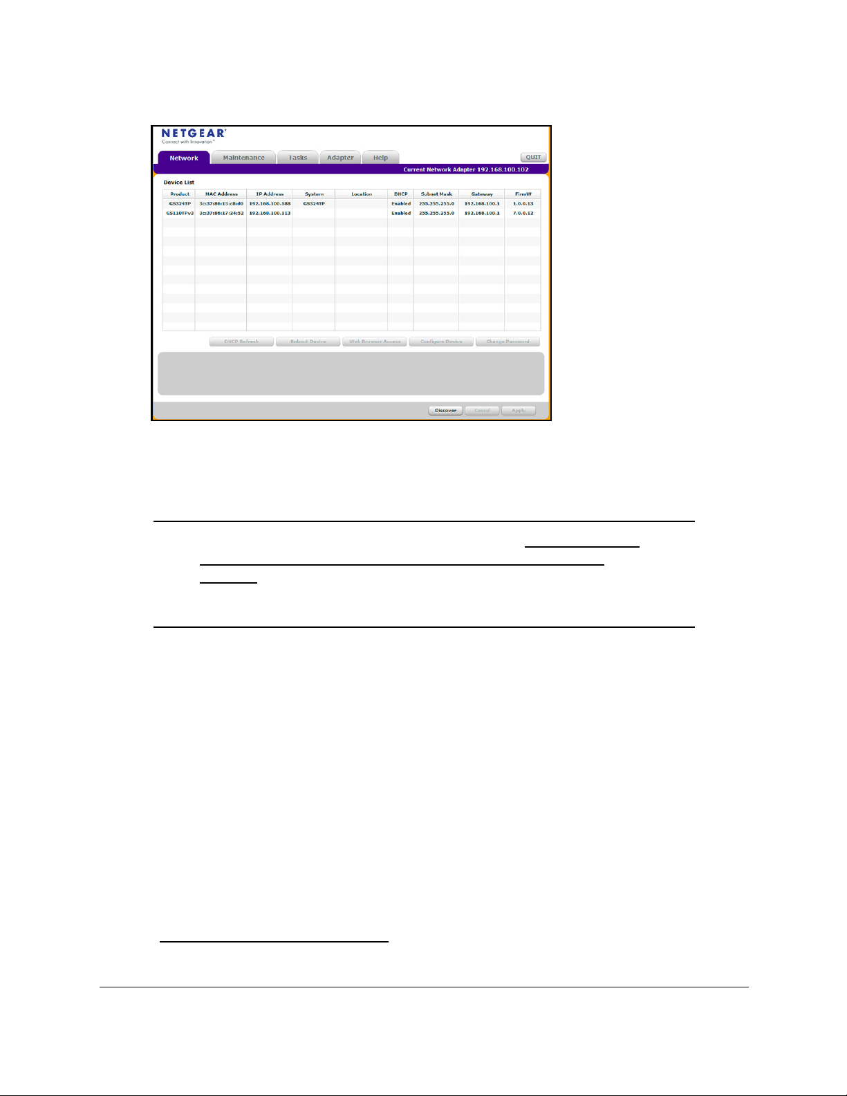
To install the switch in a network with a DHCP server:
1. Connect the switch to a network with a DHCP server.
2. Power on the switch by connecting its power cord.
3. Install the SCC on your computer
4. Start the SCC.
5. Click the Discover
button for the SCC to discover all the devices in the subnet.
https://www.netgear.com/support/product/SCC.
.
Get Started User Manual15
Page 16
8-Port Gigabit (PoE+) Ethernet Smart Managed Pro Switch with (2 SFP Ports and) Cloud Management
6. Make a note of the displayed IP address assigned by the DHCP server.
You can this use IP address later to access the switch directly from a web browser (that
is, without using the SCC).
Note: After you complete the initial log-in process (see Access the local
browser interface for the initial online log-in procedure on
page 22), you can access the local browser interface from the SCC
by selecting your switch in the SCC and clicking the
Web Browser Access button.
Discover the switch in a network without a DHCP server using the Smart Control Center
This section describes how to use the Smart Control Center (SCC) to set up your switch in a
network without a DHCP server. If your network does not include a DHCP service, you must
assign a static IP address to your switch.
If you prefer, you can assign the switch a static IP address even if your network does include
a DHCP server.
As an offline option, if you connect your computer directly to the switch using an Ethernet
cable (that is, offline), you can also use the SCC to assign a static IP address to your switch.
After you do so, you can connect your switch to the network.
For more information about the SCC, see the SCC user manual, which you can download
netgear.com/support/download/.
from
Get Started User Manual16
Page 17
8-Port Gigabit (PoE+) Ethernet Smart Managed Pro Switch with (2 SFP Ports and) Cloud Management
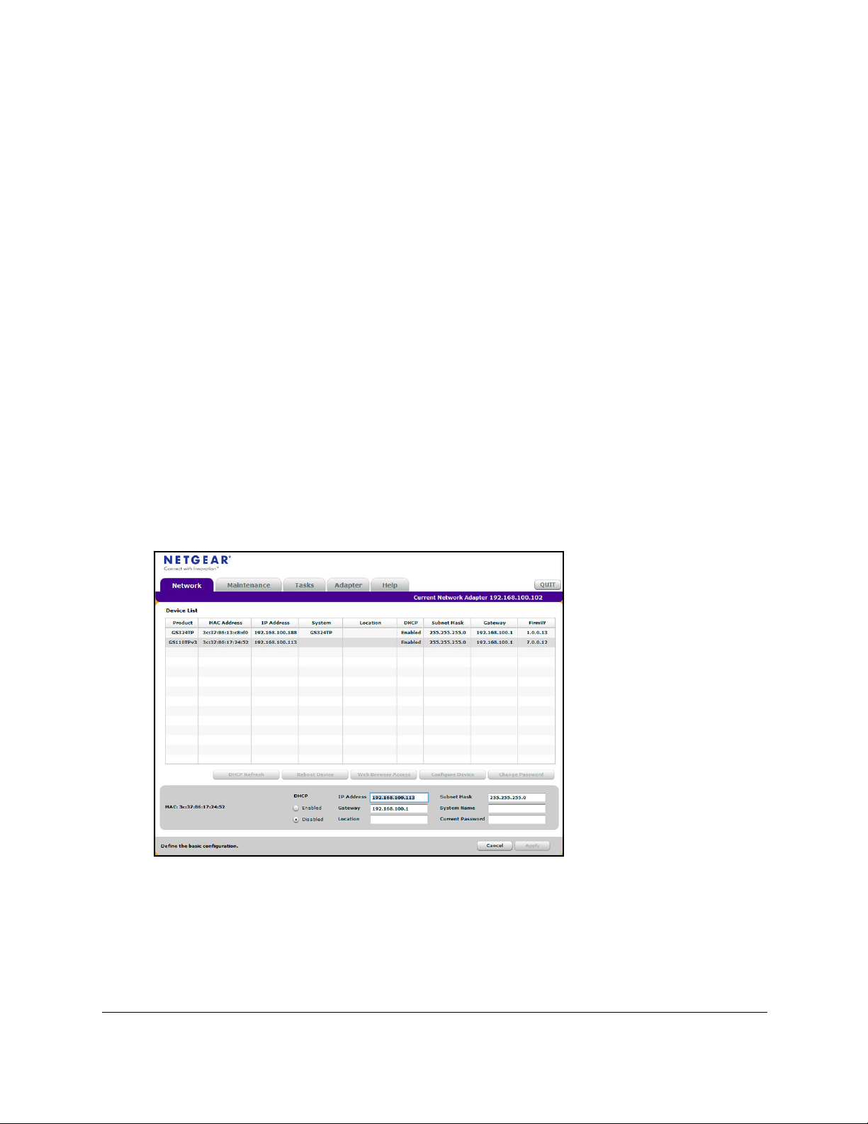
To assign a static IP address:
1. Connect the switch to your existing network or directly to your computer using an
Ethernet cable.
Note: If you connect your computer directly to the switch using an Ethernet
cable, the IP address settings of your computer do not need to be in
the same IP subnet as the switch. The SCC can detect the IP address
settings of the switch even if they are in a different subnet.
2. Power on the switch by connecting its power cord.
3. Install the SCC on your computer.
4. Start the SCC.
5. Click the Discover button for the SCC to find your switch.
The utility broadcasts Layer 2 discovery packets within the broadcast domain to discover
the switch.
6. Select the switch, and then click the Configure Device button.
The page expands to display additional fields at the bottom.
7. Select the
Disabled radio button.
DHCP is disabled.
8. Enter the static switch IP address, gateway IP address, and subnet mask for the switch.
9. Type your password to continue with the configuration change.
Tip: You must enter the current local password each time that you use the
SCC to update the switch settings. The default local password is
password
.
10. Click the Apply button.
Your settings are saved.
Get Started User Manual17
Page 18

8-Port Gigabit (PoE+) Ethernet Smart Managed Pro Switch with (2 SFP Ports and) Cloud Management
Use the NETGEAR Switch Discovery Tool to discover the switch
For easiest access, we recommend that you cable the switch to a network with a router or
DHCP server that assigns IP addresses, power on the switch, and then use a computer that
is connected to the same network as the switch.
The NETGEAR Switch Discovery Tool lets you discover the switch in your network and
access the local browser interface of the switch from a Mac or a 64-bit Windows-based
computer.
o install the NETGEAR Switch Discovery Tool and discover the switch in your
T
network:
T
1. Download the Switch Discovery
netgear.com/support/product/netgear-switch-discovery-tool.aspx.
Depending on the computer that you are using, download either the Mac version or the
version for a 64-bit Windows-based computer.
ool by visiting
2. Temporarily disable the firewall, Internet security, antivirus programs, or all of these on the
computer that you use to configure the switch.
3. Unzip the Switch Discovery T
NETGEAR+Switch+Discovery+Tool+Setup+1.2.101.exe or
NetgearSDT-V1.2.101.dmg), and install the program on your computer.
The installation process places a NETGEAR Switch Discovery Tool
desktop.
4. Reenable the security services on your computer.
5. Power on the switch.
The DHCP server assigns the switch an IP address.
6. Connect your computer to the same network as the switch.
You can use a WiFi or wired connection. The computer and the switch must be on the
same Layer 2 network.
7. Open the Switch Discovery
To open the program, double-click the NETGEAR Switch Discovery Too
desktop.
The initial page displays a menu and a button.
8. From the Choose a connection menu, select the network connection that allows the Switch
Discovery Tool
9. Click the Start Searching button.
to access the switch.
ool files, double-click the .exe or .dmg file (for example,
icon on your
T
ool.
l icon on your
The Switch Discovery Tool displays a list of Smart Managed Plus Switches that it
discovers on the selected network.
For each switch, the tool displays the IP address.
Get Started User Manual18
Page 19

8-Port Gigabit (PoE+) Ethernet Smart Managed Pro Switch with (2 SFP Ports and) Cloud Management
Use the NETGEAR Insight mobile app to discover and |register the switch
If the switch is connected to a WiFi router or access point, and the switch is connected to the
Internet, the NETGEAR Insight mobile app lets you discover the switch in your network,
register the switch with NETGEAR, activate your warranty, and access support.
To use the NETGEAR Insight mobile app to discover the switch in your network and
register the switch with NETGEAR:
1. On your iOS or
Insight, download the latest version of the app, and install the app.
2. Connect your mobile device to the WiFi network of the WiFi router or access point to which
the switch is connected.
3. Open the NETGEAR Insight mobile app.
4. If you did not set up a NETGEAR account, tap Create NETGEAR
onscreen instructions.
5. Enter the email address and password for your account and tap LOG IN.
After you log in to your account, the IP address of the switch displays in the device list.
6. W
rite down the IP address for future use.
7. Tap + in the upper-right corner.
8. Either use the camera on your phone to scan the serial number bar code located on the
bottom of the switch, or enter the serial number.
9. Tap Go
10. Follow the onscreen instructions to add your switch to a network location.
.
Android mobile device, go to the app store, search for NETGEAR
Account and follow the
The switch is registered and added to your account.
Note: To manage the switch from the Insight mobile app or the Insight Cloud
Portal, you first must change the management mode (see
the management mode of the switch on page 28).
Get Started User Manual19
Change
Page 20

8-Port Gigabit (PoE+) Ethernet Smart Managed Pro Switch with (2 SFP Ports and) Cloud Management
Configure a static IP address from a directly connected computer
You can change the IP address of the switch by connecting an Ethernet cable from a
computer to the switch.The IP address of the computer must be in the same subnet as the
default IP address on the switch. For most networks, this means that you must change the IP
address of the computer to be on the same subnet as the default IP address of the switch
(192.168.0.239).
To configure a static IP address on the switch:
1. Change the IP settings of your computer to be in the same subnet as the IP settings of
the switch.
If the DHCP client of the switch is enabled and you remove the switch from the network
with the DHCP server
with a subnet of 255.255.255.0.
Note: If you already disabled the DHCP client and assigned a static IP
address to the switch,
the same subnet a
, the IP address reverts to the default IP address of 192.168.0.239
change the IP settings of your computer to be in
s
the static IP address.
For more information about changing the IP settings on your computer, see one of the
following knowledge base articles at the NETGEAR website:
• Windows-based computer. See the following article:
https://kb.netgear.com/27476/How-to-set-a-static-IP-address-in-Windows
• Mac. See the following article:
https://kb.netgear.com/000037250/Setting-a-static-IP-address-on-your-network-a
dapter-in-Mac-OS-for-direct-access-to-an-access-point
(The Mac article is written for an access point but is also valid for a switch.)
2. Connect your computer to the switch using an Ethernet cable.
3. Power on the switch by connecting its power cord.
4. Launch a web browser
5. In the address field of your web browser, enter the IP address of the switch.
The NETGEAR Business page displays.
6. If the browser does not display the NETGEAR Business page, your browser might display a
security message and might not let you proceed until you complete one of the following
tasks, depending on which browser you use:
•
Google Chrome. If Google Chrome displays a Your connection is not private
message, click the ADVANCED link. Then, click the Proceed to x.x.x.x (unsafe) link,
in which x.x.x.x represents the IP address of the switch, and install a security
certificate.
• Apple Safari. If
the Show Details button. Then, click the visit this website link. If a warning pop-up
.
Apple Safari displays a This connection is not private message
, click
Get Started User Manual20
Page 21

8-Port Gigabit (PoE+) Ethernet Smart Managed Pro Switch with (2 SFP Ports and) Cloud Management
window opens, click the Visit Website button. If another pop-up window opens to let
you confirm changes to your certificate trust settings, enter your Mac user name and
password and click the Update Setting button.
• Mozilla Firefox. If Mozilla Firefox displays a Y
click the ADV
window that opens, click the Confirm Security Exception button and install a
security certificate.
• Microsoft Internet Explorer. If Microsoft Internet Explorer displays a There is a
problem with this website’
website (not recommended) link and install a security certificate.
• Microsoft Edge. If Microsoft Edge displays a There is a problem with this website’
security certificate message
webpage and install a security certificate.Make sure that the switch is connected to
the Internet.
7. In the Password field, enter the current local password.
If you did not change the local password, use the default local password, which is
password.
ANCED button. Then, click the Add Exception button. In the pop-up
s security certificate message, click the
or a similar warning, select Details > Go on to the
our connection is not secure message,
Continue to this
s
8. Click the Login button.
The System Information page of the switch displays.
9. Select System > Management > IP Configuration.
The IP Configuration page displays.
10. Select the Static IP
11. Configure the IP address, subnet mask, and default gateway to be assigned to the switch.
12. Click the Apply button.
Your settings are saved.
13. Disconnect the Ethernet cable and return the network configuration on your computer to the
original settings.
Address radio button.
Manage the switch by using the local browser interface
This manual describes how to use the local browser interface to manage and monitor the
switch.
For information about using the NETGEAR Insight app and Insight Cloud porta to manage
the switch, visit
netgear.com/support.
Get Started User Manual21
netgear.com/insight and see the NETGEAR knowledge base articles at
Page 22

8-Port Gigabit (PoE+) Ethernet Smart Managed Pro Switch with (2 SFP Ports and) Cloud Management
Software requirements for the local browser interface
To access the switch by using a web browser, the browser must meet the following software
requirements:
• HTML version 4.0, or later
• HTTP version 1.1, or later
Supported web browsers for the local browser interface
The following browsers were tested and support the local browser interface. Later browser
versions might function fine but were not tested. The supported web browsers include the
following:
• Microsoft Internet Explorer (IE) version 11
• Microsoft Edge
• Mozilla Firefox version 50
• Chrome version 51
• Safari on Windows OS versions 5.1
• Safari on MAC OS X version 10.1
Access the local browser interface for the initial online log-in procedure
For the initial online log-in process, also referred to as single sign-on (SSO), the following are
required:
• The switch must be connected to the Internet through an existing router in your network.
• You must know (or be able to ping) the IP address of the switch from your computer for
web access to be available.
If you do not know the IP address of the switch, see
address on page 15.
If you used the Smart Control Center to set up the IP address and subnet mask, either
with or without a DHCP server, use that IP address in the address field of your web
browser
• You must log in with a NETGEAR account. If you do not own a free NETGEAR account,
you can create one during the initial log-in process.
ou can use one of the following methods to access the switch local browser interface:
Y
• From the Smart Control Center, select the switch and click the W
button.
• From the Switch Discovery T
.
ool, select the switch and click the ADMIN PAGE button.
Discover or change the switch IP
eb Browser Access
Get Started User Manual22
Page 23

8-Port Gigabit (PoE+) Ethernet Smart Managed Pro Switch with (2 SFP Ports and) Cloud Management
• Open a web browser and enter the IP address of the switch in the address field.
If you use any of these methods and you log in for the first time to the local browser interface,
the NETGEAR Log In page displays.
To access the switch local browser interface from a web browser for the first time:
1. Connect your computer to the same network as the switch.
You can use a WiFi or wired connection to connect your computer to the network.
2. Launch a web browser.
3. In the address field of your web browser, enter the IP address of the switch.
If you do not know the IP address of the switch, see
Discover or change the switch IP
address on page 15.
The NETGEAR Business page displays the switch model.
4. If the browser does not display the NETGEAR Business page, do the following:
• Your browser might display a security message and might not let you proceed.
Consider the following examples:
Google Chrome. If Google Chrome displays a Your connection is not private
-
message, click the ADV
ANCED link. Then, click the Proceed to x.x.x.x (unsafe)
link, in which x.x.x.x represents the IP address of the switch, and install a security
certificate.
- Apple Safari. If
Apple Safari displays a This connection is not private message
click the Show Details button. Then, click the visit this website link. If a warning
pop-up window opens, click the Visit Website button. If another pop-up window
opens to let you confirm changes to your certificate trust settings, enter your Mac
user name and password and click the Update Setting button.
- Mozilla Firefox. If Mozilla Firefox displays a Y
message, click the ADV
ANCED button. Then, click the Add Exception button. In
our connection is not secure
the pop-up window that opens, click the Confirm Security Exception button and
install a security certificate.
- Microsoft Internet Explorer. If Microsoft Internet Explorer displays a There is a
problem with this website’
s security certificate message, click the
Continue to
this website (not recommended) link and install a security certificate.
- Microsoft Edge. If Microsoft Edge displays a There is a problem with this
website’s security certificate message
or a similar warning, select Details > Go
on to the webpage and install a security certificate.Make sure that the switch is
connected to the Internet.
,
• If you use a wired Ethernet connection, make sure that the computer is connected to
the same network that the switch is attached to or directly to one of the LAN Ethernet
ports of the switch.
• If you use a mobile device, make sure that mobile device is connected to an access
point that is attached to the same network that the switch is connected to or that the
access point is directly attached to one of the LAN Ethernet ports of the switch.
Get Started User Manual23
Page 24

8-Port Gigabit (PoE+) Ethernet Smart Managed Pro Switch with (2 SFP Ports and) Cloud Management
• Make sure that the switch is receiving power and that its Power LED is lit.
• Close and reopen the browser.
5. Depending on whether you already own a free NETGEAR account, do one of the following:
•
You own a NETGEAR account. Do the following:
a. Click the Login button.
The NETGEAR Account Login page displays.
b. Enter your registered email address and password and click the LOG IN button.
• You do not own a NETGEAR account. Do the following:
a. Click the Create button.
The Create NETGEAR Account page displays.
b. Set up a new account.
When you are done, the The NETGEAR Business page displays again.
c. Click the Login button.
The NETGEAR Account Login page displays.
d. Enter your registered email address and password and click the LOG IN button
The System Information page of the switch displays. You can now change the settings of
the switch.
Note: After you successfully log in to your NETGEAR account, the switch is
automatically registered with NETGEAR. If you use the NETGEAR
Insight app to discover the switch in your network (see
Use the
NETGEAR Insight mobile app to discover and |register the switch on
page 19), the switch is also automatically registered with NETGEAR.
Get Started User Manual24
Page 25
8-Port Gigabit (PoE+) Ethernet Smart Managed Pro Switch with (2 SFP Ports and) Cloud Management
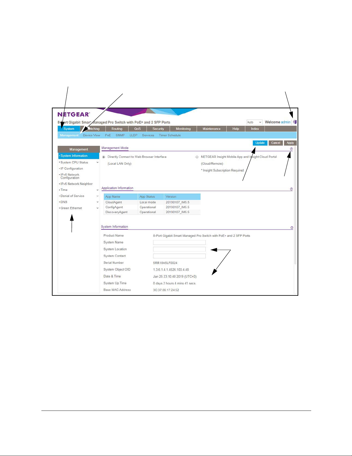
Navigation tabs, configuration menus, and page menu
The following figure shows the Switch Information page.
Navigation tabs
Page menu
Configuration menus
Logout button
Buttons
Configuration status
and options
Help page
Figure 1. Switch navigation tabs, configuration menus, and page menu
The navigation tabs along the top of the local browser interface give you quick access to the
various switch functions. The tabs are always available and remain constant, regardless of
which feature you configure.
When you select a tab, the features for that tab appear as menus directly under the tabs. The
configuration menus in the blue bar change according to the navigation tab that is selected.
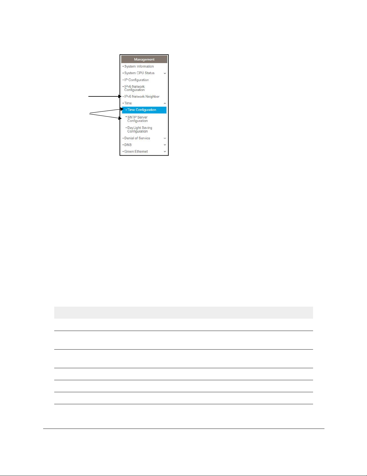
The configuration pages for each feature are available as submenu links in the page menu
on the left side of the page. Some items in the menu expand to reveal multiple submenu
links, as the following figure shows.
Get Started User Manual25
Page 26
8-Port Gigabit (PoE+) Ethernet Smart Managed Pro Switch with (2 SFP Ports and) Cloud Management
Link
Submenu
links
Figure 2. Switch page menu link and submenu links
Configuration and status options
The area directly under the configuration menus and to the right of the links displays the
configuration information or status for the page you select. On pages that contain
configuration options, you might be able to enter information into fields, select options from
menus, select check boxes, and select radio buttons.
Each page contains access to the HTML-based help that explains the fields and configuration
options for the page.
Buttons in the local browser interface
Each page also contains command buttons. The following table shows the command buttons
that are used throughout the pages in the local browser interface:
Table 1. Command buttons in the local browser interface
Button Function
Add Clicking the Add button adds the new item configured in the heading row of a table.
Apply Clicking the Apply button to save your settings. Configuration changes take effect
immediately.
Cancel Clicking the Cancel
the page to the previous values of the switch.
Delete Clicking the Delete button removes the selected item.
Update Clicking the Update button refreshes the page with the latest information from the device.
Logout Clicking the Logout button ends the session.
button cancels the configuration on the page and resets the data on
Get Started User Manual26
Page 27

8-Port Gigabit (PoE+) Ethernet Smart Managed Pro Switch with (2 SFP Ports and) Cloud Management
User-defined fields
User-defined fields can contain 1 to 159 characters, unless otherwise noted on the
configuration web page. All characters can be used except for the ones stated in the
following table (unless specifically noted in a procedure for a feature).
Table 2. Invalid characters for user-defined fields
Invalid Characters for user-defined fields
\ <
/ >
* |
?
Context-sensitive help
When you log in to the switch, every page contains a link to the online help ( ) that contains
information to assist in configuring and managing the switch. The online help pages are
context sensitive. For example, if the IP Configuration page is open, the help topic for that
page displays if you click the link to the online help.
Change the language of the local browser interface
By default, the language is set to Auto. You can set the language to a specific one.
To change the language of the local browser interface:
1. Connect your computer to the same network as the switch.
You can use a WiFi or wired connection to connect your computer to the network, or
connect directly to a switch that is off-network using an Ethernet cable.
2. Launch a web browser.
3. In the address field of your web browser, enter the IP address of the switch.
If you do not know the IP address of the switch, see
address on page 15.
The NETGEAR Business page displays. You are prompted to sign in with your
NETGEAR account.
Discover or change the switch IP
Get Started User Manual27
Page 28

8-Port Gigabit (PoE+) Ethernet Smart Managed Pro Switch with (2 SFP Ports and) Cloud Management
Note: If the switch is not connected to the Internet or off-network, you are
prompted to sign in with the local password. (The default local
password is password.)
4. Click the Login button.
The NETGEAR Account Login page displays.
5. Enter your registered email address and password and click the LOG IN button.
The System Information page displays.
6. At the top of the page, to the left of Welcome
A confirmation pop-up window opens.
7. Click the OK button to confirm.
The switch restarts and you must log in again.
The language of the local browser interface is now set to the language that you selected.
, select a language from the language menu.
Change the management mode of the switch
By default, the management mode on the switch is Directly Connect to Web Browser
Interface (which is the same as the local browser interface). You can also change the
management mode to NETGEAR Insight Mobile App and Insight Cloud Portal.
About changing the management mode
The following applies to changing the management mode:
• Changing to the NETGEAR Insight Mobile App and Insight Cloud Portal mode.
- The first time that you enable this mode, the switch is reset to its factory default
settings so that you can create the switch configuration and network topology using
the Insight app or the Insight Cloud portal.
- If you added the switch to a network on the Insight app or Insight cloud portal before,
all Insight-manageable device settings are returned to the last configuration saved on
the cloud server
Insight network password).
- If you use the Insight app or the Insight Cloud portal, you can temporarily change the
management mode of the switch back to Directly Connect to W
ou can then access the local browser interface for settings that are not
Y
Insight-manageable, for complex tasks such as integrating with an existing network of
devices that are not managed through Insight, and for debugging purposes. When
Get Started User Manual28
, including the switch password (that is, the password is reset to the
eb Browser Interface.
Page 29

8-Port Gigabit (PoE+) Ethernet Smart Managed Pro Switch with (2 SFP Ports and) Cloud Management
you are done, you can change the management mode back to NETGEAR Insight
Mobile App and Insight Cloud Portal.
• Changing back to Directly Connect to Web Browser Interface mode
- The NETGEAR Insight Mobile App and Insight Cloud Portal management mode is
disabled and the current Insight-manageable device settings are saved to the cloud
server
.
- Any changes that you make using the Directly Connect to Web Browser Interface
management mode are not saved to the cloud server
.
.
Change the management mode to NETGEAR Insight Mobile App and Insight Cloud Portal
To change the management mode of the switch to NETGEAR Insight Mobile App and
Insight Cloud Portal:
1. Connect your computer to the same network as the switch.
You can use a WiFi or wired connection to connect your computer to the network, or
connect directly to a switch that is off-network using an Ethernet cable.
2. Launch a web browser.
3. In the address field of your web browser, enter the IP address of the switch.
If you do not know the IP address of the switch, see
address on page 15.
The NETGEAR Business page displays. You are prompted to sign in with your
NETGEAR account. If you do not know how to do this, see Access the local browser
interface for the initial online log-in procedure on page 22.
Note: If the switch is not connected to the Internet or off-network, you are
prompted to sign in with the local password. (The default local
password is password.)
4. Click the Login button.
The NETGEAR Account Login page displays.
5. Enter your registered email address and password and click the LOG IN button.
The System Information page displays.
6. Select the NETGEAR Insight Mobile App and Insight Cloud Portal radio button.
A pop-up window opens.
7. Click the OK
8. Click the Apply button.
button.
Discover or change the switch IP
Another pop-up window opens.
9. Click the OK button
Get Started User Manual29
Page 30

8-Port Gigabit (PoE+) Ethernet Smart Managed Pro Switch with (2 SFP Ports and) Cloud Management
Your settings are saved. The System Information page closes and the following occurs:
• The first time that you enable this mode, the switch is reset to its factory default
settings.
• The switch connects to the cloud server.
• If you added the switch to a network on the Insight app before, all Insight-manageable
device settings are returned to the last configuration saved on the cloud server,
including the switch password (that is, the password is reset to the Insight network
password).
• The NETGEAR Business page displays again.
Y
ou can now manage the switch using the Insight mobile app or Insight Cloud Portal.
Change the management mode back to Directly Connect to Web-browser Interface
To change the management mode of the switch back to Directly Connect to Web
Browser Interface:
1. Connect your computer to the same network as the switch.
You can use a WiFi or wired connection to connect your computer to the network, or
connect directly to a switch that is off-network using an Ethernet cable.
2. Launch a web browser.
3. In the address field of your web browser, enter the IP address of the switch.
If you do not know the IP address of the switch, see
address on page 15.
The NETGEAR Business page displays. You are prompted to sign in with your
NETGEAR account. If you do not know how to do this, see Access the local browser
interface for the initial online log-in procedure on page 22.
Note: If the switch is not connected to the Internet or off-network, you are
prompted to sign in with the local password. (The default local
password is password.)
4. Click the Login button.
The NETGEAR Account Login page displays.
5. Enter your registered email address and password and click the LOG IN button.
The System Information page displays.
Discover or change the switch IP
6. Select the Directly Connect to Web Browser Interface
A pop-up window opens.
7. Click the OK button.
Get Started User Manual30
radio button.
Page 31

8-Port Gigabit (PoE+) Ethernet Smart Managed Pro Switch with (2 SFP Ports and) Cloud Management
8. Click the Apply button.
Another pop-up window opens.
9. Click the OK button
Y our settings are saved and any current Insight-manageable device settings are saved to
the cloud server
displays again.
10. Enter your registered email address and password and click the LOG IN button.
The System Information page displays. The full local browser interface is now available.
The System Information page closes and the NETGEAR Business page
.
Access the switch offline
When the switch is online (connected to the Internet), you cannot access the local browser
interface until after you complete the initial login procedure (see
interface for the initial online log-in procedure on page 22).
Access the local browser
However, when the switch offline (not connected to the Internet), you can access the local
browser interface, even if you did not yet complete the initial login procedure.
For offline access, you cannot use your registered NETGEAR email address and password.
You must use the local password. The default local password is password. However
enhanced security, we recommend that you change this password (see
login password for the local browser interface on page 278).
Change the local
, for
Access the switch offline if your network is not connected to the Internet
After you complete the initial log-in process, if the switch is connected to your network but the
network is temporarily not connected to the Internet (for example, the Internet is down), you
can log in to the switch by using the local password.
To access the switch local browser interface if the switch is connected to the network
but the network is not connected to the Internet:
1. Connect your computer directly over an Internet cable to the same network as the
switch.
You can use a WiFi or wired connection to connect your computer to the network.
2. Launch a web browser.
3. In the address field of your web browser, enter the IP address of the switch.
If you do not know the IP address of the switch, see
address on page 15.
The NETGEAR Business page displays.
Get Started User Manual31
Discover or change the switch IP
Page 32

8-Port Gigabit (PoE+) Ethernet Smart Managed Pro Switch with (2 SFP Ports and) Cloud Management
4. In the Password field, enter the current local password.
If you did not change the local password, use the default local password, which is
password.
Note: Use your registered NETGEAR email address and password only
when the switch is connected to the Internet.
5. Click the Login button.
The System Information page of the switch displays. You can now change the settings of
the switch.
Access the switch offline if your computer is connected directly to the switch
If you connect your computer directly to the switch using an Ethernet cable, you can log in to
the switch by using the local password.
To access the switch local browser interface if your computer is connected directly to
the switch through an Ethernet cable:
1. Make sure that your computer is not connected to a network or to the Internet.
2. Change the IP settings of your computer to be in the same subnet as the IP settings of the
switch.
If the DHCP client of the switch is enabled and you remove the switch from the network
with the DHCP server, the IP address reverts to the default IP address of 192.168.0.239
with a subnet of 255.255.255.0. If you disabled the DHCP client and assigned a static IP
address to the switch,
the static IP address.
For more information about changing the IP settings on your computer, see one of the
following knowledge base articles at the NETGEAR website:
• Windows-based computer. See the following article:
https://kb.netgear.com/27476/How-to-set-a-static-IP-address-in-Windows
• Mac. See the following article:
https://kb.netgear.com/000037250/Setting-a-static-IP-address-on-your-network-a
dapter-in-Mac-OS-for-direct-access-to-an-access-point
(The Mac article is written for an access point but is also valid for a switch.)
3. Connect your computer to the switch using an Ethernet cable.
4. Power on the switch by connecting its power cord.
5. In the address field of your web browser
change the IP settings of your computer to be in the same subnet as
, enter the IP address of the switch.
The NETGEAR Business page displays.
Get Started User Manual32
Page 33

8-Port Gigabit (PoE+) Ethernet Smart Managed Pro Switch with (2 SFP Ports and) Cloud Management
6. If the browser does not display the NETGEAR Business page, your browser might display a
security message and might not let you proceed until you complete one of the following
tasks, depending on which browser you use:
• Google Chrome. If Google Chrome displays a Y
message, click the ADV
in which x.x.x.x represents the IP address of the switch, and install a security
certificate.
• Apple Safari. If
Show Details button. Then, click the visit this website link. If a warning pop-up
the
window opens, click the Visit Website button. If another pop-up window opens to let
you confirm changes to your certificate trust settings, enter your Mac user name and
password and click the Update Setting button.
• Mozilla Firefox. If Mozilla Firefox displays a Y
click the ADV
window that opens, click the Confirm Security Exception button and install a
security certificate.
• Microsoft Internet Explorer. If Microsoft Internet Explorer displays a There is a
problem with this website’
website (not recommended) link and install a security certificate.
• Microsoft Edge. If Microsoft Edge displays a There is a problem with this website’s
security certificate message
webpage and install a security certificate.Make sure that the switch is connected to
the Internet.
Apple Safari displays a This connection is not private message, click
ANCED button. Then, click the Add Exception button. In the pop-up
ANCED link. Then, click the Proceed to x.x.x.x (unsafe) link,
s security certificate message, click the
or a similar warning, select Details > Go on to the
our connection is not private
our connection is not secure message,
Continue to this
7. In the Password field, enter the current local password.
If you did not change the local password, use the default local password, which is
password.
Note: Use your registered NETGEAR email address and password only
when the switch is connected to the Internet.
8. Click the Login button.
The System Information page of the switch displays. You can now change the settings of
the switch.
Use the Device View of the local browser interface
The Device View displays the ports on the switch. This graphic tool provides an alternate way
to navigate to configuration and monitoring options. The graphic tool also provides
information about device ports, configuration and status, tables, and feature components.
Get Started User Manual33
Page 34

8-Port Gigabit (PoE+) Ethernet Smart Managed Pro Switch with (2 SFP Ports and) Cloud Management
To use the Device View:
1. Connect your computer to the same network as the switch.
You can use a WiFi or wired connection to connect your computer to the network, or
connect directly to a switch that is off-network using an Ethernet cable.
2. Launch a web browser.
3. In the address field of your web browser, enter the IP address of the switch.
If you do not know the IP address of the switch, see
Discover or change the switch IP
address on page 15.
The NETGEAR Business page displays. You are prompted to sign in with your
NETGEAR account. If you do not know how to do this, see Access the local browser
interface for the initial online log-in procedure on page 22.
Note: If the switch is not connected to the Internet or off-network, you are
prompted to sign in with the local password. (The default local
password is password.)
4. Click the Login button.
The NETGEAR Account Login page displays.
5. Enter your registered email address and password and click the LOG IN button.
The System Information page displays.
6. Select System > Device View.
The Device View page displays.
The following figure shows the Device V
iew page for model GS110TPv3.
For model GS108Tv3, each port provides a left LED and a right LED that, combined,
indicate the link and speed, as described in the following table.
Table 3. Device view port LEDs for model GS108Tv3
Left port LED Right port LED Description
Solid green Solid green A valid 1 Gbps port link is established.
Solid green Black A valid 100 Mbps port link is established.
Get Started User Manual34
Page 35

8-Port Gigabit (PoE+) Ethernet Smart Managed Pro Switch with (2 SFP Ports and) Cloud Management
Table 3. Device view port LEDs for model GS108Tv3
Left port LED Right port LED Description
Black Solid green A valid 10 Mbps port link is established.
Black Black No port link is established.
Note: The LEDs in the device view do not blink to indicate activity. However,
the physical LEDs on the switch can blink to indicate activity.
For model GS1 10TPv3, each port provides a left LED that functions as the combined link
and speed LED and a right LED that indicates the PoE status, as described in the
following table.
Table 4. Device view port LEDs for model GS110TPv3
LED Description
RJ-45 left LED
Link, speed, and activity
for Ethernet ports 1 to 8
RJ-45 right LED
PoE status for Ethernet
ports 1 to 8.
Link/ACT LED
Link and activity for SFP
fiber ports 9 and 10
• Solid green.
• Solid yellow. A valid 10 Mbps or 100 Mbps port link is established.
• Black. No port link is established.
• Black
• Solid green. The port is
• Solid yellow. A PoE fault
• Black. No SFP module link is established.
• Solid green.
.
A valid 1 Gbps port link is established.
The port is not delivering PoE power.
delivering PoE power.
occurred.
A valid 1 Gbps link is established.
Note: The LEDs in the device view do not blink to indicate activity. However,
the physical LEDs on the switch can blink to indicate activity.
7. Click a port to open a menu that displays statistics and configuration options.
You can select a menu option to access the page that contains the configuration or
monitoring options.
If you right-click the graphic, but do not right-click a specific port, the main menu displays.
This menu contains the same options as the navigation tabs at the top of the page.
The following figure shows the details on the Device View page for model GS110TPv3.
Get Started User Manual35
Page 36

8-Port Gigabit (PoE+) Ethernet Smart Managed Pro Switch with (2 SFP Ports and) Cloud Management
Right-click the specific port that you want to view or configure to see a menu that displays
statistics and configuration options. Select the menu option to access the page that
contains the configuration or monitoring options.
The system LEDs are located on the left side of the front panel.
Power LED in the Device View
The Power LED is a bicolor LED that serves as an indicator of power and diagnostic status.
The Power LED must be solid green, indicating the switch is powered on and operating
normally. Other LED colors do not apply to the Device View. (If the switch is off or booting,
you cannot access the Device View.)
PoE Max LED in the Device View (model GS110TPv3)
The PoE Max LED indicates the following status:
• Off. Sufficient (more than 7W of) PoE power is available.
• Solid yellow. Less than 7W of PoE power is available.
Note: The physical PoE Max LEDs on the switch can also blink yellow,
indicating that at least once during the previous two minutes, less than
7W of PoE power was available.
Get Started User Manual36
Page 37

8-Port Gigabit (PoE+) Ethernet Smart Managed Pro Switch with (2 SFP Ports and) Cloud Management
Configure interface settings
The switch supports physical and logical interfaces. Interfaces are identified by their type and
the interface number. The physical ports are Gigabit interfaces and are numbered on the
front panel. You configure the logical interfaces by using the software.
The following table describes the naming convention for all interfaces available on the switch.
Table 5. Naming conventions for interfaces
Interface Description Example
Physical The physical ports are Gigabit Ethernet interfaces and are
numbered sequentially starting from 1.
Link aggregation group (LAG) LAG interfaces are logical interfaces that are used only for
bridging functions.
CPU management interface This is the internal switch interface responsible for the switch
base MAC address.
always listed in the MAC Address
The interface is not configurable and is
Table.
g1, g2, g12
l1, l2, l3
c1
For some features that allow you to configure interface settings, you can apply the same
settings simultaneously to any of the following:
• A single port
• Multiple ports
• All ports
• A single LAG
• Multiple LAGs
• All LAGs
• Multiple ports and LAGs
• All ports and LAGs
Many of the pages that allow you to configure or view interface settings include links to
display all ports, all LAGs, or all ports and LAGs on the page.
Use these links as follows:
• T
o display all ports, click the 1 link.
• T
o display all LAGs, click the LAG link.
• To display all ports and LAGs, click the All link.
The procedures in this section describe how to select the ports and LAGs to configure.
procedures assume that you are already logged in to the switch. If you do not know how to
log in to the switch, see
Access the local browser interface for the initial online log-in
procedure on page 22.
Get Started User Manual37
The
Page 38

8-Port Gigabit (PoE+) Ethernet Smart Managed Pro Switch with (2 SFP Ports and) Cloud Management
To configure a single port by using the Go To Interface field:
1. Ensure that the page is displaying all ports, and not only the LAGs.
2. In the Go To Interface field, type the port number
.
For example, type g4.
For more information, see
Table 5, Naming conventions for interfaces on page 37.
3. Click the Go button.
The check box associated with the interface is selected, the row for the selected interface
is highlighted, and the interface number displays in the heading row.
4. Configure the desired settings.
5. Click the Apply
button.
Your settings are saved.
To configure a single LAG by using the Go To Interface field:
1. Click the LAG link or the All link to display the LAGs.
2. In the Go T
For information, see
o Interface field, type the LAG number
Table 5, Naming conventions for interfaces on page 37.
, for example l3.
3. Click the Go button.
The check box associated with the interface is selected, the row for the selected interface
is highlighted, and the interface number appears in the heading row.
4. Configure the desired settings.
5. Click the Apply
button.
Your settings are saved.
To configure a single port:
1. Ensure that the page is displaying all ports, and not only the LAGs.
2. Select the check box next to the port number
.
The row for the selected interface is highlighted, and the interface number appears in the
heading row.
3. Configure the desired settings.
4. Click the Apply
button.
Your settings are saved.
To configure a single LAG:
1. Click the LAG link or the All link to display the LAGs.
2. Select the check box next to the LAG number
Get Started User Manual38
.
Page 39

8-Port Gigabit (PoE+) Ethernet Smart Managed Pro Switch with (2 SFP Ports and) Cloud Management
The row for the selected interface is highlighted, and the interface number appears in the
heading row.
3. Configure the desired settings.
4. Click the Apply button.
Your settings are saved.
To configure multiple ports:
1. Ensure that the page is displaying all ports, and not only the LAGs.
2. Select the check box next to each port to configure.
The row for each selected interface is highlighted.
3. Configure the desired settings.
4. Click the Apply button.
Your settings are saved.
To configure multiple LAGs:
1. Click the LAG link or the All link to display the LAGs.
2. Select the check box next to each LAG to configure.
The check box associated with each interface is selected, and the row for each selected
interface is highlighted.
3. Configure the desired settings.
4. Click the Apply button.
Your settings are saved.
To configure all ports:
1. Ensure that the page is displaying only ports, and not LAGs.
2. Select the check box in the heading row
.
The check boxes for all ports are selected and the rows for all ports are highlighted.
3. Configure the desired settings.
4. Click the Apply
button.
Your settings are saved.
To configure all LAGs:
1. Click the LAG link to display only the LAG interfaces.
2. Select the check box in the heading row
.
The check box associated with every LAG is selected, and the rows for all LAGs are
highlighted.
3. Configure the desired settings.
Get Started User Manual39
Page 40

8-Port Gigabit (PoE+) Ethernet Smart Managed Pro Switch with (2 SFP Ports and) Cloud Management
4. Click the Apply button.
Your settings are saved.
To configure multiple ports and LAGs:
1. Click the All link to display all ports and LAGs.
2. Select the check box associated with each port and LAG to configure.
The rows for the selected ports and LAGs are highlighted.
3. Configure the desired settings.
4. Click the Apply button.
Your settings are saved.
To configure all ports and LAGs:
1. Click the All link to display all ports and LAGs.
2. Select the check box in the heading row
The check box associated with every port and LAG is selected, and the rows for all ports
and LAGs are highlighted.
.
3. Configure the desired settings.
4. Click the Apply
Your settings are saved.
button.
Access the NETGEAR support website
From the local browser interface, you can access the NETGEAR support website at
netgear.com/support.
To access the support website from the local browser interface:
1. Connect your computer to the same network as the switch.
You can use a WiFi or wired connection to connect your computer to the network, or
connect directly to a switch that is off-network using an Ethernet cable.
2. Launch a web browser.
3. In the address field of your web browser, enter the IP address of the switch.
If you do not know the IP address of the switch, see
address on page 15.
Discover or change the switch IP
The NETGEAR Business page displays. You are prompted to sign in with your
NETGEAR account. If you do not know how to do this, see Access the local browser
interface for the initial online log-in procedure on page 22.
Get Started User Manual40
Page 41

8-Port Gigabit (PoE+) Ethernet Smart Managed Pro Switch with (2 SFP Ports and) Cloud Management
Note: If the switch is not connected to the Internet or off-network, you are
prompted to sign in with the local password. (The default local
password is password.)
4. Click the Login button.
The NETGEAR Account Login page displays.
5. Enter your registered email address and password and click the LOG IN button.
The System Information page displays.
6. Select Help > Support.
The Support page displays.
7. T
o access the NETGEAR support site for the switch, click the Apply
button.
Access the user manual online
The user manual (the guide you are now reading) is available at the NETGEAR download
center at
To access the user manual online from the local browser interface:
1. Connect your computer to the same network as the switch.
2. Launch a web browser.
3. In the address field of your web browser, enter the IP address of the switch.
netgear.com/support/download/.
You can use a WiFi or wired connection to connect your computer to the network, or
connect directly to a switch that is off-network using an Ethernet cable.
If you do not know the IP address of the switch, see
address on page 15.
The NETGEAR Business page displays. You are prompted to sign in with your
NETGEAR account. If you do not know how to do this, see Access the local browser
interface for the initial online log-in procedure on page 22.
Discover or change the switch IP
Note: If the switch is not connected to the Internet or off-network, you are
prompted to sign in with the local password. (The default local
password is password.)
4. Click the Login button.
The NETGEAR Account Login page displays.
5. Enter your registered email address and password and click the LOG IN button.
The System Information page displays.
6. Select Help > Online Help > User Guide.
Get Started User Manual41
Page 42

8-Port Gigabit (PoE+) Ethernet Smart Managed Pro Switch with (2 SFP Ports and) Cloud Management
The User Guide page displays.
7. To access the NETGEAR download center, click the Apply
8. Enter the model number of the switch.
9. Locate the user manual on the product support web page.
button.
Get Started User Manual42
Page 43

2
2Configure System Information
This chapter contains the following sections:
•
View or define system information
• Configure the IP network settings for management access
• Configure the time settings
• Configure denial of service settings
• Configure DNS settings
• Configure green Ethernet settings
• Use the Device View
• Configure Power over Ethernet
• Configure SNMP
• Configure LLDP
• Configure DHCP snooping
• Set up PoE timer schedules
43
Page 44

8-Port Gigabit (PoE+) Ethernet Smart Managed Pro Switch with (2 SFP Ports and) Cloud Management
View or define system information
When you log in, the System Information page displays. You can configure and view general
device information.
To view or define system information:
1. Connect your computer to the same network as the switch.
You can use a WiFi or wired connection to connect your computer to the network, or
connect directly to a switch that is off-network using an Ethernet cable.
2. Launch a web browser.
3. In the address field of your web browser, enter the IP address of the switch.
If you do not know the IP address of the switch, see
address on page 15.
The NETGEAR Business page displays. You are prompted to sign in with your
NETGEAR account. If you do not know how to do this, see Access the local browser
interface for the initial online log-in procedure on page 22.
Note: If the switch is not connected to the Internet or off-network, you are
prompted to sign in with the local password. (The default local
password is password.)
4. Click the Login button.
The NETGEAR Account Login page displays.
5. Enter your registered email address and password and click the LOG IN button.
The System Information page displays.
Discover or change the switch IP
Configure System Information User Manual44
Page 45

8-Port Gigabit (PoE+) Ethernet Smart Managed Pro Switch with (2 SFP Ports and) Cloud Management
6. Define the following fields:
• System Name. Enter the name to identify this switch. You can use up to 255
alphanumeric characters.
The default is blank.
• System Location. Enter the location of this switch. You can use up to 255
alphanumeric characters.
The default is blank.
• System Contact. Enter the contact person for this switch. You can use up to 255
alphanumeric characters.
The default is blank.
7. Click the Apply button.
Your settings are saved.
The following table describes the status information that the System Information page
displays.
Table 6. System Information
Field Description
Product Name The product name of this switch.
Serial Number The serial number of the switch.
System Object OID The base object ID for the switch's enterprise MIB.
Date & Time The current date and time.
Configure System Information User Manual45
Page 46

8-Port Gigabit (PoE+) Ethernet Smart Managed Pro Switch with (2 SFP Ports and) Cloud Management
Table 6. System Information (continued)
Field Description
System Up Time The time in days, hours, and minutes since the last switch reboot.
Base Mac Address Universally assigned hardware address of the switch.
View the software versions
You can view the software versions that are running on the switch.
To view the software versions:
1. Connect your computer to the same network as the switch.
You can use a WiFi or wired connection to connect your computer to the network, or
connect directly to a switch that is off-network using an Ethernet cable.
2. Launch a web browser.
3. In the address field of your web browser, enter the IP address of the switch.
If you do not know the IP address of the switch, see
Discover or change the switch IP
address on page 15.
The NETGEAR Business page displays. You are prompted to sign in with your
NETGEAR account. If you do not know how to do this, see Access the local browser
interface for the initial online log-in procedure on page 22.
Note: If the switch is not connected to the Internet or off-network, you are
prompted to sign in with the local password. (The default local
password is password.)
4. Click the Login button.
The NETGEAR Account Login page displays.
5. Enter your registered email address and password and click the LOG IN button.
The System Information page displays.
6. Scroll down to the Versions section.
7. To refresh the page with the latest information about the switch, click the Update button.
Configure System Information User Manual46
Page 47

8-Port Gigabit (PoE+) Ethernet Smart Managed Pro Switch with (2 SFP Ports and) Cloud Management
The following table describes the nonconfigurable information displayed in the Versions
section of the System Information page.
Table 7. Versions information
Field Description
Model Name The model name of the switch.
Boot Version The version of the bootloader software of the switch.
Software Version The version number of the software that is running on the switch.
View the system CPU status
You can monitor the CPU, memory resources, and utilization patterns across various
intervals to assess the performance, load, and stability settings of the switch.
To view the system CPU status:
1. Connect your computer to the same network as the switch.
You can use a WiFi or wired connection to connect your computer to the network, or
connect directly to a switch that is off-network using an Ethernet cable.
2. Launch a web browser.
3. In the address field of your web browser, enter the IP address of the switch.
If you do not know the IP address of the switch, see
Discover or change the switch IP
address on page 15.
The NETGEAR Business page displays. You are prompted to sign in with your
NETGEAR account. If you do not know how to do this, see Access the local browser
interface for the initial online log-in procedure on page 22.
Note: If the switch is not connected to the Internet or off-network, you are
prompted to sign in with the local password. (The default local
password is password.)
4. Click the Login button.
The NETGEAR Account Login page displays.
5. Enter your registered email address and password and click the LOG IN button.
The System Information page displays.
6. Select System > Management > System CPU Status > System CPU Status.
Configure System Information User Manual47
Page 48

8-Port Gigabit (PoE+) Ethernet Smart Managed Pro Switch with (2 SFP Ports and) Cloud Management
The CPU Utilization section shows the memory information, task-related information, and
percentage of CPU utilization per task.
The following table describes CPU Memory Status information.
Table 8. CPU Memory Status information
Field Description
Total System Memory The total memory of the switch in KBytes.
Available Memory The available memory space for the switch in KBytes.
Configure the CPU thresholds
The CPU Utilization Threshold notification feature allows you to configure thresholds that,
when exceeded, trigger a notification. The notification occurs through SNMP trap and syslog
messages.
To configure the CPU thresholds:
1. Connect your computer to the same network as the switch.
You can use a WiFi or wired connection to connect your computer to the network, or
connect directly to a switch that is off-network using an Ethernet cable.
2. Launch a web browser.
3. In the address field of your web browser, enter the IP address of the switch.
If you do not know the IP address of the switch, see
Discover or change the switch IP
address on page 15.
Configure System Information User Manual48
Page 49

8-Port Gigabit (PoE+) Ethernet Smart Managed Pro Switch with (2 SFP Ports and) Cloud Management
The NETGEAR Business page displays. You are prompted to sign in with your
NETGEAR account. If you do not know how to do this, see
Access the local browser
interface for the initial online log-in procedure on page 22.
Note: If the switch is not connected to the Internet or off-network, you are
prompted to sign in with the local password. (The default local
password is password.)
4. Click the Login button.
The NETGEAR Account Login page displays.
5. Enter your registered email address and password and click the LOG IN button.
The System Information page displays.
6. Select System > Management > System CPU Status > CPU Threshold.
7. Specify the thresholds:
• Rising Threshold. Notification is generated when the total CPU utilization exceeds
this threshold value over the configured time period. The range is 1 to 100.
• Rising Interval. This utilization monitoring time period can be configured from 5 to
86400 seconds in multiples of 5 seconds.
• Falling Threshold
. Notification is triggered when the total CPU utilization falls below
this level for a configured period of time.
The falling utilization threshold must be equal to or less than the rising threshold
value. The falling utilization threshold notification is sent only if a rising threshold
notification was sent previously. Configuring the falling utilization threshold and time
period is optional. If the Falling CPU utilization settings are not configured, the switch
uses the same values as the values that are used for the Rising CPU utilization.
range is 1 to 100.
• Falling Interval.
The utilization monitoring time period can be configured from
5 seconds to 86400 seconds in multiples of 5 seconds.
• Free Memory Threshold
. The free memory threshold value for the CPU in KB.
8. Click the Apply button.
Y
our settings are saved.
The
Configure System Information User Manual49
Page 50

8-Port Gigabit (PoE+) Ethernet Smart Managed Pro Switch with (2 SFP Ports and) Cloud Management
Configure the IP network settings for management access
You can configure network information for the local browser interface, which is the logical
interface used for in-band connectivity with the switch through any of the switch’s front-panel
ports. The settings associated with the local browser interface do not affect the configuration
of the front panel ports through which traffic is switched or routed.
Configure the IPv4 network and VLAN settings for the local browser interface
You can configure the IPv4 network information for the local browser interface, which is the
logical interface used for in-band connectivity with the switch through any of the switch’s
front-panel ports.
To configure the IPv4 network and VLAN settings for the local browser interface:
1. Connect your computer to the same network as the switch.
You can use a WiFi or wired connection to connect your computer to the network, or
connect directly to a switch that is off-network using an Ethernet cable.
2. Launch a web browser.
3. In the address field of your web browser, enter the IP address of the switch.
If you do not know the IP address of the switch, see
address on page 15.
The NETGEAR Business page displays. You are prompted to sign in with your
NETGEAR account. If you do not know how to do this, see Access the local browser
interface for the initial online log-in procedure on page 22.
Note: If the switch is not connected to the Internet or off-network, you are
prompted to sign in with the local password. (The default local
password is password.)
4. Click the Login button.
The NETGEAR Account Login page displays.
5. Enter your registered email address and password and click the LOG IN button.
Discover or change the switch IP
The System Information page displays.
6. Select System > Management > IP Configuration.
The IP Configuration page displays.
Configure System Information User Manual50
Page 51

8-Port Gigabit (PoE+) Ethernet Smart Managed Pro Switch with (2 SFP Ports and) Cloud Management
7. Select one of the following radio buttons to specify how the network information for the
switch must be configured:
• Static IP Address. Specifies that the IP address, subnet mask, and default gateway
must be manually configured. Enter this information in the fields below this radio
button.
• Dynamic IP Address (BOOTP). Specifies that the switch must obtain the IP address
through a BootP server.
Dynamic IP Address (DHCP). Specifies that the switch must obtain the IP address
•
through a DHCP server.
8. If you select the
• IP Address. The IP address of the network interface.
Static IP Address
radio button, configure the following network information:
The default value is
192.168.0.239. Each part of the IP address must start with a number other than zero.
For example, IP addresses 001.100.192.6 and 192.001.10.3 are not valid.
• Subnet Mask. The IP subnet mask for the interface.
The default value is
255.255.255.0.
• Default Gateway. The default gateway for the IP interface.
The default value is
192.168.0.254.
9. In the Management VLAN ID field, leave the default value or specify the VLAN ID for the
management VLAN.
The management VLAN is used to establish an IP connection to the switch from a
computer that is connected to a port in the same VLAN. If not specified, the active
management VLAN ID is 1 (default), which allows an IP connection to be established
through any port.
When you change the management VLAN, an IP connection can be made only through a
port that is part of the management VLAN. Also, the port VLAN ID (PVID) of the port to be
connected in that management VLAN must be the same as the management VLAN ID.
Note: Make sure that the VLAN that must be the management VLAN exists. Also
make sure that the PVID of at least one port in the VLAN is the same as
the management VLAN ID. For information about creating VLANs and
configuring the PVID for a port, see Configure VLANs on page 136.
The following requirements apply to the management VLAN:
• Only one management VLAN can be active at a time.
• When a new management VLAN is configured, connectivity through the existing
management VLAN is lost.
• The management station must be reconnected to the port in the new management
VLAN.
10. Click the Apply button.
Your settings are saved.
Configure System Information User Manual51
Page 52

8-Port Gigabit (PoE+) Ethernet Smart Managed Pro Switch with (2 SFP Ports and) Cloud Management
Configure the IPv6 network settings for the local browser interface
You can configure IPv6 network information for the local browser interface, which is the
logical interface used for in-band connectivity with the switch through any of the switch’s
front-panel ports.
To access the switch over an IPv6 network, you must initially configure the switch with IPv6
information (an IPv6 prefix, prefix length, and default gateway). Y
one of the following options:
• IPv6 auto-configuration
• DHCPv6
When in-band connectivity is established, IPv6 information can be changed using
SNMP-based management or web-based management.
To configure the IPv6 network settings for the local browser interface:
1. Connect your computer to the same network as the switch.
ou can configure IPv6 using
You can use a WiFi or wired connection to connect your computer to the network, or
connect directly to a switch that is off-network using an Ethernet cable.
2. Launch a web browser.
3. In the address field of your web browser, enter the IP address of the switch.
If you do not know the IP address of the switch, see
address on page 15.
The NETGEAR Business page displays. You are prompted to sign in with your
NETGEAR account. If you do not know how to do this, see Access the local browser
interface for the initial online log-in procedure on page 22.
Note: If the switch is not connected to the Internet or off-network, you are
prompted to sign in with the local password. (The default local
password is password.)
4. Click the Login button.
The NETGEAR Account Login page displays.
5. Enter your registered email address and password and click the LOG IN button.
The System Information page displays.
6. Select System > Management > IPv6 Network Configuration.
Discover or change the switch IP
The IPv6 Network Global Configuration page displays.
7. Ensure that the Admin Mode Enable
8. Determine how the switch acquires an IPv6 address:
Configure System Information User Manual52
radio button is selected.
Page 53

8-Port Gigabit (PoE+) Ethernet Smart Managed Pro Switch with (2 SFP Ports and) Cloud Management
• IPv6 Address Auto Configuration Mode. When this mode is enabled, the network
interface can acquire an IPv6 address through IPv6 Neighbor Discovery Protocol
(NDP) and through the use of router advertisement messages. When this mode is
disabled, the network interface does not use the native IPv6 address
auto-configuration features to acquire an IPv6 address. Auto-configuration can be
enabled only when DHCPv6 is not enabled on any of the management interfaces.
• DHCPv6. Next to Current Network Configuration Protocol, select the DHCPv6 radio
button to enable the DHCPv6 client on the interface.
network information from a DHCPv6 server
the DHCPv6 client on the network interface.
When DHCPv6 is enabled, the DHCPv6 Client DUID field displays the client identifier
used by the DHCPv6 client (if enabled) when sending messages to the DHCPv6
server.
. Selecting the None radio button disables
The switch attempts to acquire
9. In the
The gateway address is in IPv6 global or link-local address format.
10. To configure one or more static IPv6 addresses for the management interface, do the
following:
a. In the
b. In the EUI64 menu, select T
c. Click the Add button.
11. Click the Apply button.
Your settings are saved.
IPv6 Gateway field, specify the default gateway for the IPv6 network interface.
IPv6 Prefix/Prefix Length field, specify the static IPv6 prefix and prefix to the
IPv6 network interface.
The address is in the global address format.
to enable the Extended Universal Identifier (EUI)
rue
flag for IPv6 address, or select False to omit the EUI flag.
View the IPv6 network neighbor
You can view information about the IPv6 neighbors that the switch discovered through the
network interface by using the Neighbor Discovery Protocol (NDP).
To view the IPv6 Network Neighbor Table:
1. Connect your computer to the same network as the switch.
You can use a WiFi or wired connection to connect your computer to the network, or
connect directly to a switch that is off-network using an Ethernet cable.
2. Launch a web browser.
3. In the address field of your web browser, enter the IP address of the switch.
If you do not know the IP address of the switch, see
address on page 15.
Configure System Information User Manual53
Discover or change the switch IP
Page 54

8-Port Gigabit (PoE+) Ethernet Smart Managed Pro Switch with (2 SFP Ports and) Cloud Management
The NETGEAR Business page displays. You are prompted to sign in with your
NETGEAR account. If you do not know how to do this, see
Access the local browser
interface for the initial online log-in procedure on page 22.
Note: If the switch is not connected to the Internet or off-network, you are
prompted to sign in with the local password. (The default local
password is password.)
4. Click the Login button.
The NETGEAR Account Login page displays.
5. Enter your registered email address and password and click the LOG IN button.
The System Information page displays.
6. Select System > Management > IPv6 Network Neighbor.
7. To refresh the page with the latest information about the switch, click the Update button.
The following table describes the information the IPv6 Network Neighbor page displays
about each IPv6 neighbor that the switch discovered.
Table 9. IPv6 network interface neighbor table information
Field Description
IPv6 address The IPv6 address of the neighbor that was detected by the switch.
MAC address The MAC address of the neighbor.
IsRtr • true (1). The
• false (2). The neighbor is
Neighbor State The state of the neighboring switch:
• reachable (1).
• stale (2)
• delay (3). No information was received from the neighbor during the delay period.
• probe (4). The
• unknown (5). The status is
Last Updated The last time that the neighbor information was updated.
neighbor is
The neighbor is reachable by th3 switch.
. Information about the neighbor is scheduled for deletion.
switch is
a router.
not a router.
attempting to probe for the neighbor.
unknown.
Configure System Information User Manual54
Page 55

8-Port Gigabit (PoE+) Ethernet Smart Managed Pro Switch with (2 SFP Ports and) Cloud Management
Configure the time settings
The switch supports the Simple Network Time Protocol (SNTP). As its name suggests, it is a
less complicated version of Network Time Protocol, which is a system for synchronizing the
clocks of networked computer systems, primarily when data transfer is handled through the
Internet. You can also set the system time manually.
Configure the time settings manually
You can view and adjust date and time settings.
To manually configure the time setting:
1. Connect your computer to the same network as the switch.
You can use a WiFi or wired connection to connect your computer to the network, or
connect directly to a switch that is off-network using an Ethernet cable.
2. Launch a web browser.
3. In the address field of your web browser, enter the IP address of the switch.
If you do not know the IP address of the switch, see
address on page 15.
The NETGEAR Business page displays. You are prompted to sign in with your
NETGEAR account. If you do not know how to do this, see Access the local browser
interface for the initial online log-in procedure on page 22.
Note: If the switch is not connected to the Internet or off-network, you are
prompted to sign in with the local password. (The default local
password is password.)
4. Click the Login button.
The NETGEAR Account Login page displays.
5. Enter your registered email address and password and click the LOG IN button.
The System Information page displays.
6. Select System > Management > T
ime > Time Configuration.
Discover or change the switch IP
Configure System Information User Manual55
Page 56

8-Port Gigabit (PoE+) Ethernet Smart Managed Pro Switch with (2 SFP Ports and) Cloud Management
7. Select the Clock Source Local radio button.
8. In the Date field, specify the current date by entering the month, day, and year
(MM/DD/YYYY).
9. In the
Time field, specify the current time by entering in hours, minutes, and seconds
(HH:MM:SS).
Note: If you do not enter a date and time, the switch calculates the date and
time using the CPU’s clock cycle.
10. In the T
Y
different from the Coordinated Universal Time (UTC).
display of the current system time. The default value is UTC.
Note: When using SNTP/NTP time servers to update the switch’s clock, the
11. In the Offset Hours field, specify the number of hours that the time zone is dif
UTC.
For more information see the description for
range is –12 to 13. The default value is 0.
12. In the Offset Minutes field, specify the number of minutes that the time zone is different
from UTC.
For more information see the description for Time Zone Name in
range is 0 to 59. The default value is 0.
13. Click the Apply button.
Your settings are saved.
ime Zone Name field, specify the acronym for a time zone.
ou can also specify the number of hours and number of minutes that the time zone is
The time zone can affect the
time data received from the server is based on the UTC, which is the
same as Greenwich Mean Time (GMT). This might not be the time
zone in which the switch is located.
ferent from the
Time Zone Name in
Step 10. The allowed
Step 10. The allowed
Configure the time settings with SNTP and configure the global SNTP settings
To configure the time by using SNTP and configure the global SNTP settings:
1. Connect your computer to the same network as the switch.
You can use a WiFi or wired connection to connect your computer to the network, or
connect directly to a switch that is off-network using an Ethernet cable.
2. Launch a web browser.
3. In the address field of your web browser, enter the IP address of the switch.
If you do not know the IP address of the switch, see
address on page 15.
Configure System Information User Manual56
Discover or change the switch IP
Page 57

8-Port Gigabit (PoE+) Ethernet Smart Managed Pro Switch with (2 SFP Ports and) Cloud Management
The NETGEAR Business page displays. You are prompted to sign in with your
NETGEAR account. If you do not know how to do this, see
Access the local browser
interface for the initial online log-in procedure on page 22.
Note: If the switch is not connected to the Internet or off-network, you are
prompted to sign in with the local password. (The default local
password is password.)
4. Click the Login button.
The NETGEAR Account Login page displays.
5. Enter your registered email address and password and click the LOG IN button.
The System Information page displays.
6. Select System > Management > T
Time Configuration page displays.
The
ime > Time Configuration.
7. Select the Clock Source SNTP radio button.
The local clock can be set to SNTP only if the following two conditions are met:
• An SNTP server is configured.
• The switch can contact the SNTP server
.
8. Next to Client Mode, select the mode of operation of the SNTP client:
• Unicast. SNTP operates in a point-to-point fashion. A unicast client sends a request
to a designated server at its unicast address and expects a reply from which it can
determine the time and, optionally, the round-trip delay and local clock of
to the server.
Configure System Information User Manual57
fset relative
Page 58

8-Port Gigabit (PoE+) Ethernet Smart Managed Pro Switch with (2 SFP Ports and) Cloud Management
• Broadcast. SNTP operates in the same manner as multicast mode but uses a local
broadcast address instead of a multicast address. The broadcast address provides a
single-subnet scope while a multicast address provides an Internet-wide scope.
The default value is Unicast.
9. If the SNTP client mode is Unicast, use the SNTP Server Configuration page to add the IP
address or DNS name of one or more SNTP servers for the switch to poll.
For more information, see
Configure an SNTP server on page 61.
10. In the Port field, specify the local UDP port that the SNTP client receives server packets on.
The allowed range is 1025 to 65535 and 123. The default value is 123. When the default
value is configured, the actual client port value used in SNTP packets is assigned by the
switch.
11. In the Unicast Poll Interval field, specify the number of seconds between unicast poll
requests expressed as a power of 2. The allowed range is 6 to 10.
The default value is 6.
12. In the Broadcast Poll Interval field, specify the number of seconds between broadcast poll
requests expressed as a power of 2.
Broadcasts received prior to the expiry of this interval are discarded. The allowed range is
6 to 10.
13. In the Unicast Poll Timeout
The default value is 6.
field, specify the number of seconds to wait for an SNTP
response to a unicast poll request.
The allowed range is 1 to 30. The default value is 5.
14. In the Unicast Poll Retry field, specify the number of times to retry a unicast poll request to
an SNTP server after the first time-out before the switch attempts to use the next configured
server.
The allowed range is 0 to 10.
The default value is 1.
15. In the Time Configuration section (above the SNTP Global Configuration section),
configure the following settings:
a. In the Time Zone Name
field, specify the acronym for a time zone.
You can also specify the number of hours and number of minutes that the time zone
is different from the Coordinated Universal Time (UTC).
The time zone can affect the
display of the current system time. The default value is UTC.
Note: When using SNTP/NTP time servers to update the switch’s clock, the
time data received from the server is based on the UTC, which is the
same as Greenwich Mean Time (GMT). This might not be the time
zone in which the switch is located.
b. In the Offset Hours field, specify the number of hours that the time zone is dif
from the UTC.
For more information see the description for
Time Zone Name in
Step a. The allowed
range is –12 to 13. The default value is 0.
Configure System Information User Manual58
ferent
Page 59

8-Port Gigabit (PoE+) Ethernet Smart Managed Pro Switch with (2 SFP Ports and) Cloud Management
c. In the Offset Minutes field, specify the number of minutes that the time zone is
different from UTC.
For more information see the description for Time Zone Name in
range is 0 to 59. The default value is 0.
16. Click the Apply button.
Your settings are saved.
Step a. The allowed
View the SNTP global status
When you select the SNTP option as the clock source, you can view the SNTP global status.
To view the SNTP global status:
1. Connect your computer to the same network as the switch.
You can use a WiFi or wired connection to connect your computer to the network, or
connect directly to a switch that is off-network using an Ethernet cable.
2. Launch a web browser.
3. In the address field of your web browser, enter the IP address of the switch.
If you do not know the IP address of the switch, see
address on page 15.
The NETGEAR Business page displays. You are prompted to sign in with your
NETGEAR account. If you do not know how to do this, see Access the local browser
interface for the initial online log-in procedure on page 22.
Discover or change the switch IP
Note: If the switch is not connected to the Internet or off-network, you are
prompted to sign in with the local password. (The default local
password is password.)
4. Click the Login button.
The NETGEAR Account Login page displays.
5. Enter your registered email address and password and click the LOG IN button.
The System Information page displays.
6. Select System > Management > Time > Time Configuration.
7. Make sure that the Clock Source SNTP radio button is selected.
The SNTP Global Status section displays below the SNTP Global Configuration section.
Configure System Information User Manual59
Page 60

8-Port Gigabit (PoE+) Ethernet Smart Managed Pro Switch with (2 SFP Ports and) Cloud Management
8. Click the Update button to update the page with the latest information about the switch.
The following table displays the nonconfigurable SNTP Global Status information.
Table 10. SNTP Global Status information
Field Description
Version The SNTP version that the client supports.
Supported mode The SNTP modes that the client supports. Multiple modes can be supported by a client.
Last Update Time The local date and time (UTC) that the SNTP client last updated the system clock.
Last Attempt Time The local date and time (UTC) of the last SNTP request or receipt of an unsolicited
message.
Last Attempt Status The status of the last SNTP request or unsolicited message for both unicast and
broadcast modes. If no message was received from a server
displayed.
• Other.
• Success. The SNTP operation
• Request Timed Out. After an SNTP request was sent to an SNTP server, the
• Bad
• Version
• Server Unsynchronized.
These values are appropriate for all operational modes.
The status of the last request is unknown.
was successful and the system time was updated.
response timer expired before a response from the server was received.
Date Encoded.
Not Supported. The SNTP version
compatible with the version supported by the client.
is indicated by the leap indicator field in the SNTP message.
The time provided by the SNTP server is not valid.
supported by the server is not
The SNTP server is not synchronized with its peers. This
, a status of Other is
Server IP
Address Type The address type of the SNTP server address for the last received valid packet.
Server Stratum The claimed stratum of the server for the last received valid packet.
Address The IP address of the server for the last received valid packet. If no message was
received from any server, an empty string is shown.
Configure System Information User Manual60
Page 61

8-Port Gigabit (PoE+) Ethernet Smart Managed Pro Switch with (2 SFP Ports and) Cloud Management
Table 10. SNTP Global Status information (continued)
Field Description
Reference Clock ID The reference clock identifier of the server for the last received valid packet.
Server mode The mode of the server for the last received valid packet.
Unicast Server Max
Entries
Unicast Server
Current Entries
Broadcast Count The number of unsolicited broadcast SNTP messages that were received and processed
The maximum number of unicast server entries that can be configured on this client.
The number of current valid unicast server entries configured for this client.
by the SNTP client since the last reboot.
Configure an SNTP server
SNTP assures accurate network device clock time synchronization up to the millisecond.
Time synchronization is performed by a network SNTP server. The switch operates only as
an SNTP client and cannot provide time services to other systems.
Time sources are established by strata. Strata define the accuracy of the reference clock.
The higher the stratum (where zero is the highest), the more accurate the clock. The device
receives time from Stratum 1 and above since it is itself a Stratum 2 device.
The following is an example of strata:
• Stratum 0.
• Stratum 1.
time servers provide primary network time standards.
Stratum 2. The time source is distanced from the Stratum 1 server over a network path.
•
For example, a Stratum 2 server receives the time over a network link, through NTP
a Stratum 1 server.
A real-time clock is used as the time source, for example, a GPS system.
A server that is directly linked to a Stratum 0 time source is used. Stratum 1
, from
Information received from SNTP servers is evaluated based on the time level and server
type.
SNTP time definitions are assessed and determined by the following time levels:
•T1. Time that the original request was sent by the client.
•T2. Time that the original request was received by the server.
•T
3. Time that the server sent a reply.
•T
4. Time that the client received the server's reply.
The device can poll unicast server types for the server time.
Polling for unicast information is used for polling a server for which the IP address is known.
SNTP servers that were configured on the device are the only ones that are polled for
synchronization information. T1 through
T4 are used to determine server time. This is the
preferred method for synchronizing device time because it is the most secure method. If this
Configure System Information User Manual61
Page 62

8-Port Gigabit (PoE+) Ethernet Smart Managed Pro Switch with (2 SFP Ports and) Cloud Management
method is selected, SNTP information is accepted only from SNTP servers defined on the
device using the SNTP Server Configuration page.
The device retrieves synchronization information, either by actively requesting information or
at every poll interval.
Y ou can view and modify information for adding and modifying Simple Network T ime Protocol
SNTP servers.
Add an SNTP server
To add an SNTP server:
1. Connect your computer to the same network as the switch.
You can use a WiFi or wired connection to connect your computer to the network, or
connect directly to a switch that is off-network using an Ethernet cable.
2. Launch a web browser.
3. In the address field of your web browser, enter the IP address of the switch.
If you do not know the IP address of the switch, see
address on page 15.
The NETGEAR Business page displays. You are prompted to sign in with your
NETGEAR account. If you do not know how to do this, see Access the local browser
interface for the initial online log-in procedure on page 22.
Note: If the switch is not connected to the Internet or off-network, you are
prompted to sign in with the local password. (The default local
password is password.)
4. Click the Login button.
The NETGEAR Account Login page displays.
5. Enter your registered email address and password and click the LOG IN button.
The System Information page displays.
6. Select System > Management > Time > SNTP Server Configuration.
The SNTP Server Configuration page displays.
7. From the
The address can be an IPv4 address, IPv6 address, or host name (DNS).
Server Type menu, select the type of SNTP address to enter in the address field.
Discover or change the switch IP
8. In the Address
This is a text string of up to 64 characters, containing the encoded unicast IP address or
host name of an SNTP server. Unicast SNTP requests are sent to this address. If this
address is a DNS host name, then that host name is resolved into an IP address each
time an SNTP request is sent to it.
Configure System Information User Manual62
field, specify the IP address or the host name of the SNTP server.
Page 63

8-Port Gigabit (PoE+) Ethernet Smart Managed Pro Switch with (2 SFP Ports and) Cloud Management
9. If the UDP port on the SNTP server to which SNTP requests are sent is not the standard
port (123), specify the port number in the Port field.
The range is from 1 to 65535. The default value is 123.
10. In the Priority field, specify the priority order which to query the servers.
The SNTP client on the device continues sending SNTP requests to different servers until
a successful response is received, or all servers are exhausted.
order in which to query the servers.
The request is sent to an SNTP server with a priority
The priority indicates the
value of 1 first, then to a server with a priority value of 2, and so on. If any servers are
assigned the same priority, the SNTP client contacts the servers in the order that they
appear in the table. The range is from 1 to 3. The default value is 1.
11. In the V
The range is 1 to 4.
ersion field, specify the NTP version running on the server.
The default value is 4.
12. Click the Add button.
The SNTP server entry is added.
13. Repeat the previous steps to add additional SNTP servers.
You can configure up to three SNTP servers.
The SNTP Server Status table displays status information about the SNTP servers
configured on your switch.
The following table describes the SNTP Server Global Status
information.
Table 11. SNTP Server Status information
Field Description
Address All the existing server addresses. If no server configuration exists, a message stating
that no SNTP server exists displays on the page.
Last Update Time The local date and time (UTC) that the response from this server was used to update
the system clock.
Last Attempt Time The local date and time (UTC) that this SNTP server was last queried.
Configure System Information User Manual63
Page 64

8-Port Gigabit (PoE+) Ethernet Smart Managed Pro Switch with (2 SFP Ports and) Cloud Management
Table 11. SNTP Server Status information (continued)
Field Description
Last Attempt Status The status of the last SNTP request or unsolicited message for both unicast and
broadcast modes. If no message was received from a server, a status of Other is
displayed. These values are appropriate for all operational modes:
• Other.
received.
• Success
• Request
response timer expired before a response from the server was received.
• Bad Date Encoded.
• V
compatible with the version supported by the client.
• Server
is indicated by the leap indicator field on the SNTP message.
• Server Kiss Of Death. The
be sent to this server. This is indicated by a stratum field equal to 0 in a message
received from a server.
The status of the last request is unknown, or no SNTP responses were
.
The SNTP operation was successful and the system time was updated.
Timed Out. After an SNTP request was sent to an SNTP server
The time provided by the SNTP server is not valid.
ersion Not Supported. The SNTP version supported by the server is not
Unsynchronized. The
SNTP
server is not synchronized with its peers. This
SNTP
server indicated that no further queries were to
, the
Requests The number of SNTP requests made to this server since last agent reboot.
Failed Requests The number of failed SNTP requests made to this server since the last reboot.
Change the settings for an existing SNTP server
To change the settings for an existing SNTP server:
1. Connect your computer to the same network as the switch.
You can use a WiFi or wired connection to connect your computer to the network, or
connect directly to a switch that is off-network using an Ethernet cable.
2. Launch a web browser.
3. In the address field of your web browser, enter the IP address of the switch.
If you do not know the IP address of the switch, see
address on page 15.
The NETGEAR Business page displays. You are prompted to sign in with your
NETGEAR account. If you do not know how to do this, see Access the local browser
interface for the initial online log-in procedure on page 22.
Note: If the switch is not connected to the Internet or off-network, you are
prompted to sign in with the local password. (The default local
password is password.)
Discover or change the switch IP
4. Click the Login button.
The NETGEAR Account Login page displays.
5. Enter your registered email address and password and click the LOG IN button.
Configure System Information User Manual64
Page 65

8-Port Gigabit (PoE+) Ethernet Smart Managed Pro Switch with (2 SFP Ports and) Cloud Management
The System Information page displays.
6. Select System > Management > Time > SNTP Server Configuration.
The SNTP Server Configuration page displays.
7. Select the check box next to the configured server.
8. Specify new values in the available fields.
9. Click the Apply
Your settings are saved.
button.
Remove an SNTP server
To remove an SNTP server:
1. Connect your computer to the same network as the switch.
You can use a WiFi or wired connection to connect your computer to the network, or
connect directly to a switch that is off-network using an Ethernet cable.
2. Launch a web browser.
3. In the address field of your web browser, enter the IP address of the switch.
If you do not know the IP address of the switch, see
address on page 15.
The NETGEAR Business page displays. You are prompted to sign in with your
NETGEAR account. If you do not know how to do this, see Access the local browser
interface for the initial online log-in procedure on page 22.
Note: If the switch is not connected to the Internet or off-network, you are
prompted to sign in with the local password. (The default local
password is password.)
4. Click the Login button.
The NETGEAR Account Login page displays.
5. Enter your registered email address and password and click the LOG IN button.
The System Information page displays.
6. Select System > Management > Time > SNTP Server Configuration.
The SNTP Server Configuration page displays.
7. Select the check box next to the configured server to remove.
8. Click the Delete
The entry is removed, and the device is updated.
button.
Discover or change the switch IP
Configure System Information User Manual65
Page 66

8-Port Gigabit (PoE+) Ethernet Smart Managed Pro Switch with (2 SFP Ports and) Cloud Management
Configure daylight saving time settings
You can configure settings for summer time, which is also known as daylight saving time.
Used in some countries around the world, summer time is the practice of temporarily
advancing clocks during the summer months. Typically clocks are adjusted forward one or
more hours near the start of spring and are adjusted backward in autumn.
To configure the daylight saving time settings:
1. Connect your computer to the same network as the switch.
You can use a WiFi or wired connection to connect your computer to the network, or
connect directly to a switch that is off-network using an Ethernet cable.
2. Launch a web browser.
3. In the address field of your web browser, enter the IP address of the switch.
If you do not know the IP address of the switch, see
address on page 15.
The NETGEAR Business page displays. You are prompted to sign in with your
NETGEAR account. If you do not know how to do this, see Access the local browser
interface for the initial online log-in procedure on page 22.
Note: If the switch is not connected to the Internet or off-network, you are
prompted to sign in with the local password. (The default local
password is password.)
4. Click the Login button.
The NETGEAR Account Login page displays.
5. Enter your registered email address and password and click the LOG IN button.
The System Information page displays.
6. Select System > Management > T
ime > DayLight Saving Configuration.
Discover or change the switch IP
Configure System Information User Manual66
Page 67

8-Port Gigabit (PoE+) Ethernet Smart Managed Pro Switch with (2 SFP Ports and) Cloud Management
7. Select a Daylight Saving (DST) radio button:
• Disable. Disable daylight saving time.
• Recurring. Daylight saving time occurs at the same time every year. The start and
end times and dates for the time shift must be manually configured.
• Recurring EU. The system clock uses the standard recurring summer time settings
used in countries in the European Union. When this option is selected, the rest of the
applicable fields on the page are automatically populated and cannot be edited.
• Recurring USA.
The system clock uses the standard recurring daylight saving time
settings used in the United States. When this option is selected, the rest of the
applicable fields on the page are automatically populated and cannot be edited.
• Non Recurring
. Daylight saving time settings are in effect only between the start date
and end date of the specified year. When this option is selected, the summer time
settings do not repeat on an annual basis.
8. Depending on your selection, configure the additional fields:
• If you select the DayLight Saving (DST)
Recurring, Recurring EU, or Recurring
USA radio button, the fields in the following table are visible and you must configure
them.
Table 12. Daylight saving setting is Recurring, Recurring EU, or Recurring USA
Field Description
Begins At These fields are used to configure the start values of the date and time.
• Week. Configure the start week in the month.
• Day. Configure the start day in the week.
• Month. Configure the start month.
• Hours. Configure the start hour
• Minutes. Configure the start minutes.
Ends At These fields are used to configure the end values of date and time.
• Week. Configure the end week in the month.
• Day. Configure the end day in the week.
• Month. Configure the end month.
• Hours. Configure the end hour
• Minutes. Configure the end minutes.
Of
fset Configure recurring offset in minutes. The range is from 1 to 1440 minutes.
Zone Configure the time zone.
.
.
Configure System Information User Manual67
Page 68

8-Port Gigabit (PoE+) Ethernet Smart Managed Pro Switch with (2 SFP Ports and) Cloud Management
• If you select the DayLight Saving (DST) Non Recurring radio button, the fields in the
following table are visible and you must configure them.
Table 13. Daylight saving setting is Non Recurring
Field Description
Begins At These fields are used to configure the start values of the date and time.
• Month. Configure the start month.
• Date. Configure the start date in the month.
• Year. Configure the start year
• Hours. Configure the start hour.
• Minutes. Configure the start minutes.
Ends At These fields are used to configure the end values of date and time.
• Month. Configure the end month.
• Date. Configure the end date in the month.
• Year. Configure the end year
• Hours. Configure the end hour.
• Minutes. Configure the end minutes.
.
.
Of
fset Specify the number of minutes to shift the summer time from the standard time.
The range is from 1 to 1440 minutes.
Zone Specify the acronym associated with the time zone when summer time is in
ef
fect. This field is not validated against an of
ficial list of time zone acronyms.
9. Click the Apply button.
Your settings are saved.
View the daylight saving time status
The Daylight Saving (DST) Status section shows information about the summer time settings
and whether the time shift for summer time is currently in effect.
To view the daylight saving time status:
1. Connect your computer to the same network as the switch.
You can use a WiFi or wired connection to connect your computer to the network, or
connect directly to a switch that is off-network using an Ethernet cable.
2. Launch a web browser.
3. In the address field of your web browser, enter the IP address of the switch.
If you do not know the IP address of the switch, see
address on page 15.
The NETGEAR Business page displays. You are prompted to sign in with your
NETGEAR account. If you do not know how to do this, see Access the local browser
interface for the initial online log-in procedure on page 22.
Configure System Information User Manual68
Discover or change the switch IP
Page 69

8-Port Gigabit (PoE+) Ethernet Smart Managed Pro Switch with (2 SFP Ports and) Cloud Management
Note: If the switch is not connected to the Internet or off-network, you are
prompted to sign in with the local password. (The default local
password is password.)
4. Click the Login button.
The NETGEAR Account Login page displays.
5. Enter your registered email address and password and click the LOG IN button.
The System Information page displays.
6. Select System > Management > Time > DayLight Saving Configuration.
7. To refresh the page, click the Update button.
The following table displays the nonconfigurable daylight saving status information.
Table 14. Daylight Saving (DST) Status information
Field Description
Daylight Saving (DST) The Daylight Saving value, which is one of the following:
• Disable
• Recurring
• Recurring EU
• Recurring USA
• Non Recurring
Begins At The start date of daylight saving time. This field is not displayed when
daylight saving time is disabled.
Ends At The end date of daylight saving time. This field is not displayed when
daylight saving time is disabled.
Offset (in Minutes) The offset value in minutes.This field is not displayed when daylight saving
time is disabled.
Configure System Information User Manual69
Page 70

8-Port Gigabit (PoE+) Ethernet Smart Managed Pro Switch with (2 SFP Ports and) Cloud Management
Table 14. Daylight Saving (DST) Status information (continued)
Field Description
Zone The zone acronym. This field is not displayed when daylight saving time is
disabled.
Daylight Saving (DST) in Effect Indicates whether daylight saving time is in effect.
Configure denial of service settings
You can configure the denial of service (DoS) settings for the switch. The switch provides
support for classifying and blocking specific types of DoS attacks.
Configure Auto-DoS
You can automatically enable all the DoS features available on the switch, except for the L4
Port attack. For information about the types of DoS attacks the switch can monitor and block,
Configure denial of service on page 71.
see
To enable the Auto-DoS feature:
1. Connect your computer to the same network as the switch.
You can use a WiFi or wired connection to connect your computer to the network, or
connect directly to a switch that is off-network using an Ethernet cable.
2. Launch a web browser.
3. In the address field of your web browser, enter the IP address of the switch.
If you do not know the IP address of the switch, see
address on page 15.
The NETGEAR Business page displays. You are prompted to sign in with your
NETGEAR account. If you do not know how to do this, see Access the local browser
interface for the initial online log-in procedure on page 22.
Note: If the switch is not connected to the Internet or off-network, you are
prompted to sign in with the local password. (The default local
password is password.)
4. Click the Login button.
The NETGEAR Account Login page displays.
5. Enter your registered email address and password and click the LOG IN button.
Discover or change the switch IP
The System Information page displays.
6. Select System > Management > Denial of Service > Auto-DoS Configuration.
Configure System Information User Manual70
Page 71

8-Port Gigabit (PoE+) Ethernet Smart Managed Pro Switch with (2 SFP Ports and) Cloud Management
The Auto-DoS Configuration page displays.
7. Select the Auto-DoS Mode Enable
When an attack is detected, a warning message is logged to the buffered log and is sent
to the syslog server.
manually by the admin user.
8. Click the Apply button.
Your settings are saved.
At the same time, the port is shut down and can be enabled only
radio button.
Configure denial of service
You can select which types of denial of service (DoS) attacks the switch monitors and blocks.
To configure individual DoS settings:
1. Connect your computer to the same network as the switch.
You can use a WiFi or wired connection to connect your computer to the network, or
connect directly to a switch that is off-network using an Ethernet cable.
2. Launch a web browser.
3. In the address field of your web browser, enter the IP address of the switch.
If you do not know the IP address of the switch, see
address on page 15.
Discover or change the switch IP
The NETGEAR Business page displays. You are prompted to sign in with your
NETGEAR account. If you do not know how to do this, see Access the local browser
interface for the initial online log-in procedure on page 22.
Note: If the switch is not connected to the Internet or off-network, you are
prompted to sign in with the local password. (The default local
password is password.)
4. Click the Login button.
The NETGEAR Account Login page displays.
5. Enter your registered email address and password and click the LOG IN button.
The System Information page displays.
6. Select System > Management > Denial of Service > Denial of Service Configuration.
Configure System Information User Manual71
Page 72

8-Port Gigabit (PoE+) Ethernet Smart Managed Pro Switch with (2 SFP Ports and) Cloud Management
7. Select the types of DoS attacks for the switch to monitor and block and configure any
associated values:
• Denial of Service Min TCP Header Size. Specify the minimum
allowed. If you select the Denial of Service TCP Fragment
TCP header size
radio button, the switch
drops the first TCP fragment with a TCP payload packet for which the minimum TCP
header size is larger than the IP payload length minus the IP header size. The range
for the minimum TCP header size is from 0 to 31. The default value is 20.
• Denial of Service Max ICMP Packet Size. Specify the maximum ICMPv4 packet
size allowed. If ICMPv4 DoS prevention or ICMPv6 DoS prevention is enabled, the
switch drops ICMPv4 or ICMPv6 ping packets with a size greater than the configured
value.
Denial of Service ICMPv4. Enabling ICMPv4 DoS prevention causes the switch to
•
The range is from 0 to 16376. The default value is 512.
drop ICMPv4 packets with a type set to ECHO_REQ (ping) and a size greater than
the configured ICMPv4 packet size.
• Denial of Service ICMPv6. Enabling ICMPv6 DoS prevention causes the switch to
drop ICMPv6 packets with a type set to ECHO_REQ (ping) and a size greater than
the configured ICMPv6 packet size.
• Denial of Service Ping of Death. Enabling Ping of Death DoS prevention causes the
switch to drop ICMP ping packets that are larger than 65535 bytes.
• Denial of Service IPv6 Fragment. Enabling IPv6 Fragment DoS prevention causes
the switch to drop IPv6 packets that contain a fragment header with the more flag set
to 1 and for which the payload length less than 1240.
Configure System Information User Manual72
Page 73

8-Port Gigabit (PoE+) Ethernet Smart Managed Pro Switch with (2 SFP Ports and) Cloud Management
• Denial of Service ICMP Fragment. Enabling ICMP Fragment DoS prevention
causes the switch to drop ICMP fragmented packets.
• Denial of Service Smurf. Enabling Smurf DoS prevention causes the switch to drop
broadcast ICMP echo request packet.
• Denial of Service SIP=DIP. Enabling SIP=DIP DoS prevention causes the switch to
drop packets with a source IP address equal to the destination IP address.
• Denial of Service SMAC=DMAC. Enabling SMAC=DMAC DoS prevention causes
the switch to drop packets with a source MAC address equal to the destination MAC
address.
• Denial of Service TCP FIN&URG&PSH. Enabling TCP FIN & URG & PSH DoS
prevention causes the switch to drop packets with
TCP flags FIN, URG, and PSH set
and the TCP sequence number equal to 0.
• Denial of Service TCP Flag&Sequence. Enabling TCP Flag DoS prevention causes
the switch to drop packets with
TCP control flags set to 0 and the TCP sequence
number set to 0.
• Denial of Service TCP Fragment. Enabling TCP Fragment DoS prevention causes
the switch to drop packets with a
TCP payload for which the IP payload length minus
the IP header size is less than the minimum allowed TCP header size.
• Denial of Service TCP Offset. Enabling TCP Of
fset DoS prevention causes the
switch to drop packets with a TCP header offset set to 1.
• Denial of Service TCP Port. Enabling TCP Port DoS prevention causes the switch to
drop packets for which the
TCP source port is equal to the TCP destination port.
• Denial of Service TCP Source Port. Enabling TCP Source Port DoS prevention
causes the switch to drop packets for which the
TCP source port number is lower
than 1024.
• Denial of Service TCP SYN&FIN. Enabling TCP SYN & FIN DoS prevention causes
the switch to drop packets with
TCP flags SYN and FIN set.
• Denial of Service TCP SYN&RST. Enabling TCP SYN & RST DoS prevention
causes the switch to drop packets with
TCP flags SYN and RST set.
• Denial of Service UDP Port. Enabling UDP Port DoS prevention causes the switch
to drop packets for which the UDP source port is equal to the UDP destination port.
8. Click the Apply button.
Your settings are saved.
Configure System Information User Manual73
Page 74

8-Port Gigabit (PoE+) Ethernet Smart Managed Pro Switch with (2 SFP Ports and) Cloud Management
Configure DNS settings
You can configure information about DNS servers that the network uses and how the switch
operates as a DNS client.
Configure the global DNS settings and add a DNS server
You can configure the global DNS settings and DNS server information.
To configure the global DNS settings and add a DNS server:
1. Connect your computer to the same network as the switch.
You can use a WiFi or wired connection to connect your computer to the network, or
connect directly to a switch that is off-network using an Ethernet cable.
2. Launch a web browser.
3. In the address field of your web browser, enter the IP address of the switch.
If you do not know the IP address of the switch, see
address on page 15.
The NETGEAR Business page displays. You are prompted to sign in with your
NETGEAR account. If you do not know how to do this, see Access the local browser
interface for the initial online log-in procedure on page 22.
Note: If the switch is not connected to the Internet or off-network, you are
prompted to sign in with the local password. (The default local
password is password.)
4. Click the Login button.
The NETGEAR Account Login page displays.
5. Enter your registered email address and password and click the LOG IN button.
The System Information page displays.
6. Select System > Management > DNS > DNS Configuration.
Discover or change the switch IP
Configure System Information User Manual74
Page 75

8-Port Gigabit (PoE+) Ethernet Smart Managed Pro Switch with (2 SFP Ports and) Cloud Management
7. Select the Disable or Enable radio button to specify whether to disable or enable the
administrative status of the DNS client.
• Enable.
Allows the switch to send DNS queries to a DNS server to resolve a DNS
domain name. The DNS is enabled by default.
•
Disable. Prevents the switch from sending DNS queries.
8. In the DNS Default Name field, enter the default DNS domain name to include in DNS
queries.
When the system is performing a lookup on an unqualified host name, this field is
provides the domain name (for example, if default domain name is netgear
user enters test, then test is changed to test.netgear.com to resolve the name).
.com and the
The name
must not be longer than 255 characters.
9. In the DNS Server field, specify the IPv4 address to which the switch sends DNS queries.
10. Click the Add button.
The server is added to the list. You can specify up to eight DNS servers. The Preference
field displays the server preference order. The preference is set in the order in which
preferences were entered.
1
1. Click the Apply button.
Your settings are saved.
The following table displays DNS Server Configuration information.
Table 15. DNS Server Configuration information
Field Description
ID The identification of the DNS Server.
Preference Shows the preference of the DNS server. The preferences are
determined by the order in which they were entered.
Configure System Information User Manual75
Page 76

8-Port Gigabit (PoE+) Ethernet Smart Managed Pro Switch with (2 SFP Ports and) Cloud Management
Remove a DNS server
You can remove a DNS server that you no longer need.
To remove a DNS server:
1. Connect your computer to the same network as the switch.
You can use a WiFi or wired connection to connect your computer to the network, or
connect directly to a switch that is off-network using an Ethernet cable.
2. Launch a web browser.
3. In the address field of your web browser, enter the IP address of the switch.
If you do not know the IP address of the switch, see
address on page 15.
The NETGEAR Business page displays. You are prompted to sign in with your
NETGEAR account. If you do not know how to do this, see Access the local browser
interface for the initial online log-in procedure on page 22.
Note: If the switch is not connected to the Internet or off-network, you are
prompted to sign in with the local password. (The default local
password is password.)
4. Click the Login button.
The NETGEAR Account Login page displays.
5. Enter your registered email address and password and click the LOG IN button.
The System Information page displays.
6. Select System > Management > DNS > DNS Configuration.
7. In the DNS Server Configuration table, select the check box for the DNS server.
Note: If you do not select a DNS server, all the DNS servers are removed
after you click the
Delete button.
Discover or change the switch IP
8. Click the Delete button.
The DNS server is removed.
Configure System Information User Manual76
Page 77

8-Port Gigabit (PoE+) Ethernet Smart Managed Pro Switch with (2 SFP Ports and) Cloud Management
Configure and view host name-to-IP address information
You can manually map host names to IP addresses or view dynamic host mappings.
Add a static entry to the dynamic host mapping table
To add a static entry to the local dynamic host mapping table:
1. Connect your computer to the same network as the switch.
You can use a WiFi or wired connection to connect your computer to the network, or
connect directly to a switch that is off-network using an Ethernet cable.
2. Launch a web browser.
3. In the address field of your web browser, enter the IP address of the switch.
If you do not know the IP address of the switch, see
address on page 15.
The NETGEAR Business page displays. You are prompted to sign in with your
NETGEAR account. If you do not know how to do this, see Access the local browser
interface for the initial online log-in procedure on page 22.
Note: If the switch is not connected to the Internet or off-network, you are
prompted to sign in with the local password. (The default local
password is password.)
4. Click the Login button.
The NETGEAR Account Login page displays.
5. Enter your registered email address and password and click the LOG IN button.
The System Information page displays.
6. Select System > Management > DNS > Host Configuration.
Discover or change the switch IP
7. In the Host Name (1 to 255 characters) field, specify the static host name to add.
Configure System Information User Manual77
Page 78

8-Port Gigabit (PoE+) Ethernet Smart Managed Pro Switch with (2 SFP Ports and) Cloud Management
Its length cannot exceed 255 characters and it is a required field.
8. In the IPv4/IPv6 Address field, enter the IP address to associate with the host name.
9. Click the Add button.
Your settings are saved. The entry displays in the Dynamic Host Mapping table.
Remove an entry from the dynamic host mapping table
To remove an entry from the Dynamic Host Mapping table:
1. Connect your computer to the same network as the switch.
You can use a WiFi or wired connection to connect your computer to the network, or
connect directly to a switch that is off-network using an Ethernet cable.
2. Launch a web browser.
3. In the address field of your web browser, enter the IP address of the switch.
If you do not know the IP address of the switch, see
address on page 15.
The NETGEAR Business page displays. You are prompted to sign in with your
NETGEAR account. If you do not know how to do this, see Access the local browser
interface for the initial online log-in procedure on page 22.
Note: If the switch is not connected to the Internet or off-network, you are
prompted to sign in with the local password. (The default local
password is password.)
4. Click the Login button.
The NETGEAR Account Login page displays.
5. Enter your registered email address and password and click the LOG IN button.
The System Information page displays.
6. Select System > Management > DNS > Host Configuration.
The DNS Host Configuration page displays.
7. Select the check box next to the entry to remove.
8. Click the Delete button.
Discover or change the switch IP
The entry is removed from the Dynamic Host Mapping table.
Configure System Information User Manual78
Page 79

8-Port Gigabit (PoE+) Ethernet Smart Managed Pro Switch with (2 SFP Ports and) Cloud Management
Change the host name or IP address in an entry of the dynamic host mapping
table, view all entries, or clear all entries
T o change the host name or IP address in an entry of the Dynamic Host Mapping table,
view all entries, or clear all entries
1. Connect your computer to the same network as the switch.
You can use a WiFi or wired connection to connect your computer to the network, or
connect directly to a switch that is off-network using an Ethernet cable.
2. Launch a web browser.
3. In the address field of your web browser, enter the IP address of the switch.
If you do not know the IP address of the switch, see
Discover or change the switch IP
address on page 15.
The NETGEAR Business page displays. You are prompted to sign in with your
NETGEAR account. If you do not know how to do this, see
Access the local browser
interface for the initial online log-in procedure on page 22.
Note: If the switch is not connected to the Internet or off-network, you are
prompted to sign in with the local password. (The default local
password is password.)
4. Click the Login button.
The NETGEAR Account Login page displays.
5. Enter your registered email address and password and click the LOG IN button.
The System Information page displays.
6. Select System > Management > DNS > Host Configuration.
The DNS Host Configuration page display.
7. Select the check box next to the entry to update.
8. Enter the new information in the appropriate field.
9. Click the Apply button.
Your settings are saved.
10. T
o clear all the dynamic host name entries from the list, click the Clear
button.
The Dynamic Host Mapping table shows host name-to-IP address entries that the switch
learned. The following table describes the dynamic host fields.
Table 16. Dynamic Host Mapping information
Field Description
Host Lists the host name that you assign to the specified IP address.
Total Time since the dynamic entry was first added to the table.
Configure System Information User Manual79
Page 80

8-Port Gigabit (PoE+) Ethernet Smart Managed Pro Switch with (2 SFP Ports and) Cloud Management
Table 16. Dynamic Host Mapping information (continued)
Field Description
Elapsed Time since the dynamic entry was last updated.
Type The type of the dynamic entry.
IPv4/IPv6 Addresses Lists the IP address associated with the host name.
Configure green Ethernet settings
You can configure the green Ethernet features to reduce power consumption.
Configure the global green Ethernet settings
You can configure the global green Ethernet settings.
To configure the global green Ethernet settings:
1. Connect your computer to the same network as the switch.
You can use a WiFi or wired connection to connect your computer to the network, or
connect directly to a switch that is off-network using an Ethernet cable.
2. Launch a web browser.
3. In the address field of your web browser, enter the IP address of the switch.
If you do not know the IP address of the switch, see
address on page 15.
The NETGEAR Business page displays. You are prompted to sign in with your
NETGEAR account. If you do not know how to do this, see Access the local browser
interface for the initial online log-in procedure on page 22.
Note: If the switch is not connected to the Internet or off-network, you are
prompted to sign in with the local password. (The default local
password is password.)
4. Click the Login button.
The NETGEAR Account Login page displays.
5. Enter your registered email address and password and click the LOG IN button.
Discover or change the switch IP
The System Information page displays.
6. Select System > Management > Green Ethernet > Green Ethernet Configuration.
Configure System Information User Manual80
Page 81

8-Port Gigabit (PoE+) Ethernet Smart Managed Pro Switch with (2 SFP Ports and) Cloud Management
7. Select the Auto Power Down Mode Disable or Enable radio button.
By default, this mode is disabled. When a port link is down, the underlying physical layer
goes down for a short period and then checks for port link pulses again so that
auto-negotiation remains possible. In this way, the switch saves power when no link
partner is present for the port.
8. Select the EEE Mode Disable
By default, this mode is disabled. Energy Efficient Ethernet (EEE) combines the MAC
with a family of physical layers that support operation in a low power mode. It is defined
by the IEEE 802.3az standard. Lower power mode enables both the send and receive
sides of the link to disable some functionality for power savings when the load is light.
ransition to low power mode does not change the link status. Frames in transit are not
T
dropped or corrupted in transition to and from low power mode. T
transparent to upper layer protocols and applications.
9. Click the Apply button.
Your settings are saved.
or Enable radio button.
Configure green Ethernet interface settings
You can configure green Ethernet settings for individual interfaces.
To configure the green Ethernet interface settings:
1. Connect your computer to the same network as the switch.
You can use a WiFi or wired connection to connect your computer to the network, or
connect directly to a switch that is off-network using an Ethernet cable.
ransition time is
2. Launch a web browser.
3. In the address field of your web browser, enter the IP address of the switch.
If you do not know the IP address of the switch, see
address on page 15.
The NETGEAR Business page displays. You are prompted to sign in with your
NETGEAR account. If you do not know how to do this, see Access the local browser
interface for the initial online log-in procedure on page 22.
Note: If the switch is not connected to the Internet or off-network, you are
prompted to sign in with the local password. (The default local
password is password.)
Configure System Information User Manual81
Discover or change the switch IP
Page 82

8-Port Gigabit (PoE+) Ethernet Smart Managed Pro Switch with (2 SFP Ports and) Cloud Management
4. Click the Login button.
The NETGEAR Account Login page displays.
5. Enter your registered email address and password and click the LOG IN button.
The System Information page displays.
6. Select System > Management > Green Ethernet > Green Ethernet Interface
Configuration.
7. Select one or more interfaces by taking one of the following actions:
• To configure a single interface, select the check box associated with the port, or type
the port number in the Go T
o Interface field and click the Go button.
• To configure multiple interfaces with the same settings, select the check box
associated with each interface.
• To configure all interfaces with the same settings, select the check box in the heading
row
.
8. From the Auto Power Down Mode menu, select
Enable or Disable.
By default, this mode is disabled for the port. When a port link is down, the underlying
physical layer goes down for a short period and then checks for port link pulses again so
that auto-negotiation remains possible. In this way, the switch saves power when no link
partner is present for the port.
9. From the EEE mode
menu, select Enable or Disable.
By default, this mode is disabled for the port. Energy Efficient Ethernet (EEE) combines
the MAC with a family of physical layers that support operation in a low power mode. It is
defined by the IEEE 802.3az standard. Lower power mode enables both the send and
receive sides of the link to disable some functionality for power savings when the load is
Transition to low power mode does not change the link status. Frames in transit are
light.
not dropped or corrupted in transition to and from low power mode.
Transition time is
transparent to upper layer protocols and applications.
10. Click the Apply button.
Your settings are saved.
Configure System Information User Manual82
Page 83

8-Port Gigabit (PoE+) Ethernet Smart Managed Pro Switch with (2 SFP Ports and) Cloud Management
Use the Device View
For information about the device view, see Use the Device View of the local browser
interface on page 33.
Configure Power over Ethernet
For model GS110TPv3, you can configure the global Power over Ethernet (PoE)
configuration settings and the PoE settings for each port.
Note: For more information about PoE, see the hardware installation guide,
which you can download by visiting
netgear.com/support/download/.
Configure the global PoE settings
To configure the PoE settings:
1. Connect your computer to the same network as the switch.
You can use a WiFi or wired connection to connect your computer to the network, or
connect directly to a switch that is off-network using an Ethernet cable.
2. Launch a web browser.
3. In the address field of your web browser, enter the IP address of the switch.
If you do not know the IP address of the switch, see
address on page 15.
The NETGEAR Business page displays. You are prompted to sign in with your
NETGEAR account. If you do not know how to do this, see Access the local browser
interface for the initial online log-in procedure on page 22.
Note: If the switch is not connected to the Internet or off-network, you are
prompted to sign in with the local password. (The default local
password is password.)
4. Click the Login button.
Discover or change the switch IP
The NETGEAR Account Login page displays.
5. Enter your registered email address and password and click the LOG IN button.
The System Information page displays.
Configure System Information User Manual83
Page 84

8-Port Gigabit (PoE+) Ethernet Smart Managed Pro Switch with (2 SFP Ports and) Cloud Management
6. Select System > PoE > Basic > PoE Configuration.
The previous figure shows the PoE Configuration page for model GS110TPv3.
7. In the System Usage Threshold field, enter a number from 1 to 99 to set the threshold level
at which a trap is sent if the consumed power exceeds the threshold power.
8. From the Power Management Mode
menu, select the power management algorithm that
the switch uses to deliver power to the requesting powered devices (PDs):
• Static. Specifies that the power allocated for each port depends on the type of power
threshold configured on the port.
• Dynamic. Specifies that the power consumption on each port is measured and
calculated in real time.
9. To active the PoE traps, from the Traps
menu, select Enable.
Selecting Disable deactivates the PoE traps. The default setting is Enabled.
10. Click the Apply button.
Y
our settings are saved.
The following table describes the nonconfigurable fields on the page.
Table 17. PoE Configuration fields
Field Description
Firmware Version The firmware version of the PoE firmware component.
Power Status The power status.
Total Power Available Watts The maximum amount of power in watts that the switch can deliver to all ports.
Threshold Power Watts If the consumed power is below the threshold power, the switch can power up
another port.
power.
Note: The threshold power value is determined by the value that you enter in the
System Usage Threshold field.
Consumed Power Watts The total amount of power in watts that is being delivered to all ports.
The consumed power can be between the nominal and threshold
The threshold power is displayed in watts.
Configure the PoE port settings
To configure the PoE port settings:
1. Connect your computer to the same network as the switch.
You can use a WiFi or wired connection to connect your computer to the network, or
connect directly to a switch that is off-network using an Ethernet cable.
Configure System Information User Manual84
Page 85

8-Port Gigabit (PoE+) Ethernet Smart Managed Pro Switch with (2 SFP Ports and) Cloud Management
2. Launch a web browser.
3. In the address field of your web browser, enter the IP address of the switch.
If you do not know the IP address of the switch, see
Discover or change the switch IP
address on page 15.
The NETGEAR Business page displays. You are prompted to sign in with your
NETGEAR account. If you do not know how to do this, see Access the local browser
interface for the initial online log-in procedure on page 22.
Note: If the switch is not connected to the Internet or off-network, you are
prompted to sign in with the local password. (The default local
password is password.)
4. Click the Login button.
The NETGEAR Account Login page displays.
5. Enter your registered email address and password and click the LOG IN button.
The System Information page displays.
6. Select System > PoE > Advanced > PoE Port Configuration.
The previous figure shows the PoE Port Configuration page for model GS110TPv3.
7. Select the check boxes for the ports that you want to configure or select the check box in the
heading to configure all ports.
8. From the Port Power menu, select the PoE mode of the port:
• Enable. The port’s capacity to deliver power is enabled.
This is the default setting.
• Disable. The port’s capacity to deliver power is disabled.
9. From the
Port Priority menu, select the priority for the port in relation to other ports if the
total power that the switch is capable of delivering exceeds the total power budget:
• Low. Low priority. This is the default setting.
Medium. Medium priority.
•
• High. High priority.
• Critical
. Critical priority.
The port priority determines which ports can still deliver power after the total power
delivered by the switch exceeds the total power budget. (In such a situation, the switch
might not be able to deliver power to all connected devices.) If the same priority applies to
two ports, the lower-numbered port receives higher priority
Configure System Information User Manual85
.
Page 86

8-Port Gigabit (PoE+) Ethernet Smart Managed Pro Switch with (2 SFP Ports and) Cloud Management
10. From the Power Mode menu, select the PoE mode that the port must function in:
• 802.3af. The port is powered in and limited to the IEEE 802.3af mode.
A PD that
requires IEEE 802.3at does not receive power if the port functions in IEEE 802.3af
mode.
• Legacy. The port is powered using high-inrush current, which is used by legacy PDs
that require more than 15W to power up.
•
Pre-802.3at. The port is initially powered in the IEEE 802.3af mode and, before
75 msec pass, is switched to the high power IEEE 802.3at mode. Select this mode if
the PD does not perform Layer 2 classification or if the switch performs
2-event Layer 1 classification.
•
802.3at. The port is powered in the IEEE 802.3at mode and is backward compatible
with IEEE 802.3af.
The 802.3at mode is the default mode. In this mode, if the switch
detects that the attached PD requests more power than IEEE 802.3af but is not an
IEEE 802.3at Class 4 device, the PD does not receive power from the switch.
11. From the Power Limit Type menu, select how the port controls the maximum power that it
can deliver:
•
None.
The port draws up to Class 0 maximum power in low power mode and up to
Class 4 maximum power in high power mode.
•
Class. The port power limit is equal to the class of the attached PD.
•
User. The port power limit is equal to the value that is specified in the Power Limit
(mW)
field. This is the default setting.
Note: If a PD does not report its class correctly, use of these options can
preserve additional PoE power by preventing the switch from
delivering more power than the PD requires. However, depending on
which option you select, a PD that does not report its class correctly
might not power up at all.
12. In the Power Limit (mW) field, enter the maximum power (in mW) that the port can deliver
The range is 3,000–30,000 mW
. The default is 30,000 mW.
13. From the Detection Type menu, select how the port detects the attached PD:
•
IEEE 802. The port performs a 4-point resistive detection.
This is the default setting.
• 4pt802.3af+legacy. The port performs a 4-point resistive detection, and if required,
continues with legacy detection.
•
Legacy. The port performs legacy detection.
14. From the Timer
Schedule menu, select a timer schedule or select None, which is the
default selection.
For information about setting up and configuring PoE timer schedules, see
Set up PoE
timer schedules on page 118.
15. Click the Apply button.
Your settings are saved.
.
Configure System Information User Manual86
Page 87

8-Port Gigabit (PoE+) Ethernet Smart Managed Pro Switch with (2 SFP Ports and) Cloud Management
The following table describes the nonconfigurable fields on the page.
Table 18. PoE Port Configuration
Field Description
High Power All ports supports high power mode.
Power Limit (mW) The maximum power in milliwatts that can be provided by the port.
Class The class defines the range of power that a powered device (PD) is drawing from
the switch.
• 0: 0.44–16.2W
• 1: 0.44–4.2W
• 2: 0.44–7.4W
• 3: 0.44–16.2W
• 4: 0.44–31.6W
• Unknown.
The class definitions are as follows:
The class cannot be detected, or no PD is attached to the port.
Output Voltage (V
Output Current (mA) The current that is delivered to the PD in mA.
Output Power (mW) The power that is delivered to the PD in milliwatts.
Status The operational status of the port:
Fault Status The error description when the PoE port is in a fault state:
olts) The voltage that is delivered to the PD in volts.
• Disabled. No power is delivered.
• Delivering Power. Power is being drawn by the PD.
• Requesting Power.
• Fault. A problem occurred with the power
• Searching. The port is not in one of the other states in this list.
• No Error.
• MPS
preventing the port from providing power
• Short.
providing power.
• Overload
than allowed by the port’s settings, preventing the port from providing power at
all.
• Power
because of an administrative condition. In this condition, the port cannot
provide power.
• Startup
condition, the port does not provide power.
• Over
• Under V
lockout.
• Thermal Shutdown
the port from providing power.
The port is not in any error state and can provide power.
Absent. The port detected the absence of the main power supply,
The port detected a short circuit condition, preventing the port from
.
The PD that is connected to the port attempts to draw more power
Denied.
Failure.
Voltage.
oltage. The port was denied power because of an under-voltage
The port is requesting power.
The port was denied power because of a shortage of power or
The PD that is connected to the port failed to start up. In this
The port was denied power because of a over-voltage lockout.
. The
port detected
a thermal temperature fault, preventing
.
.
Configure System Information User Manual87
Page 88

8-Port Gigabit (PoE+) Ethernet Smart Managed Pro Switch with (2 SFP Ports and) Cloud Management
Configure SNMP
You can configure SNMP settings for SNMPv1/v2 and SNMPv3. The switch software
supports the configuration of SNMP groups and users that can manage traps that the SNMP
agent generates.
The switch uses both standard public MIBs for standard functionality and private MIBs that
support additional switch functionality.
main object for interface configuration is in -SWITCHING-MIB, which is a private MIB. Some
interface configurations also involve objects in the public MIB, IF-MIB.
Configure the SNMPv1 and SNMPv2 community
Only the communities that you define can access to the switch using the SNMP V1 and
SNMP V2 protocols. Only those communities with read/write level access can be used to
change the configuration using SNMP.
All private MIBs begin with a hyphen (-) prefix. The
Add an SNMP community:
To add an SNMP community:
1. Connect your computer to the same network as the switch.
You can use a WiFi or wired connection to connect your computer to the network, or
connect directly to a switch that is off-network using an Ethernet cable.
2. Launch a web browser.
3. In the address field of your web browser, enter the IP address of the switch.
If you do not know the IP address of the switch, see
address on page 15.
The NETGEAR Business page displays. You are prompted to sign in with your
NETGEAR account. If you do not know how to do this, see Access the local browser
interface for the initial online log-in procedure on page 22.
Note: If the switch is not connected to the Internet or off-network, you are
prompted to sign in with the local password. (The default local
password is password.)
4. Click the Login button.
The NETGEAR Account Login page displays.
Discover or change the switch IP
5. Enter your registered email address and password and click the LOG IN button.
The System Information page displays.
6. Select System > SNMP > SNMP V1/V2 > Community Configuration.
Configure System Information User Manual88
Page 89

8-Port Gigabit (PoE+) Ethernet Smart Managed Pro Switch with (2 SFP Ports and) Cloud Management
7. In the Management Station IP field, specify the IP address of the management station.
8. In the Management Station IP Mask field, specify the subnet mask to associate with the
management station IP address.
Together, the management station IP address and the management station IP mask
denote a range of IP addresses from which SNMP clients can use that community to
access this device. If either the management station IP address or management station
IP mask value is 0.0.0.0, access is allowed from any IP address. Otherwise, every client’s
address is ANDed with the mask, as is the management station IP address. If the values
are equal, access is allowed.
For example, if the management station IP address and management station IP mask
settings are 192.168.1.0/255.255.255.0, any client with an IP address in the range from
192.168.1.0 to 192.168.1.255 (inclusive) is allowed access. To allow access from only
one station, use a management station IP mask value of 255.255.255.255, and use that
computer
’s IP address as the client address.
9. In the Community String field, specify a community name.
10. From the Access Mode menu, select the access level for this community, which is either
Read/Write
11. From the Status menu, select to enable or disable the community.
If you select Enable
names or the set requests are rejected. If you select Disable, the community name
becomes invalid.
12. Click the Add button.
The selected community is added.
or Read Only.
, the community name must be unique among all valid community
Modify an existing SNMP community
To modify an existing SNMP community:
1. Connect your computer to the same network as the switch.
You can use a WiFi or wired connection to connect your computer to the network, or
connect directly to a switch that is off-network using an Ethernet cable.
2. Launch a web browser.
3. In the address field of your web browser, enter the IP address of the switch.
If you do not know the IP address of the switch, see
address on page 15.
Discover or change the switch IP
Configure System Information User Manual89
Page 90

8-Port Gigabit (PoE+) Ethernet Smart Managed Pro Switch with (2 SFP Ports and) Cloud Management
The NETGEAR Business page displays. You are prompted to sign in with your
NETGEAR account. If you do not know how to do this, see
interface for the initial online log-in procedure on page 22.
Note: If the switch is not connected to the Internet or off-network, you are
prompted to sign in with the local password. (The default local
password is password.)
4. Click the Login button.
The NETGEAR Account Login page displays.
5. Enter your registered email address and password and click the LOG IN button.
The System Information page displays.
6. Select System > SNMP > SNMP V1/V2 > Community Configuration.
The Community Configuration page displays.
7. Select the check box next to the community.
8. Update the desired fields.
9. Click the Apply
button.
Access the local browser
Your settings are saved.
Delete an SNMP community
To delete an SNMP community:
1. Connect your computer to the same network as the switch.
You can use a WiFi or wired connection to connect your computer to the network, or
connect directly to a switch that is off-network using an Ethernet cable.
2. Launch a web browser.
3. In the address field of your web browser, enter the IP address of the switch.
If you do not know the IP address of the switch, see
address on page 15.
The NETGEAR Business page displays. You are prompted to sign in with your
NETGEAR account. If you do not know how to do this, see Access the local browser
interface for the initial online log-in procedure on page 22.
Note: If the switch is not connected to the Internet or off-network, you are
prompted to sign in with the local password. (The default local
password is password.)
Discover or change the switch IP
4. Click the Login button.
The NETGEAR Account Login page displays.
5. Enter your registered email address and password and click the LOG IN button.
Configure System Information User Manual90
Page 91

8-Port Gigabit (PoE+) Ethernet Smart Managed Pro Switch with (2 SFP Ports and) Cloud Management
The System Information page displays.
6. Select System > SNMP > SNMP V1/V2 > Community Configuration.
The Community Configuration page displays.
7. Select the check box next to the community to remove.
8. Click the Delete button.
The community is removed.
Configure SNMPv1 and SNMPv2 trap settings
You can configure settings for each SNMPv1 or SNMPv2 management host that must
receive notifications about traps generated by the device. The SNMP management host is
also known as the SNMP trap receiver.
Add an SNMP Trap Receiver
To add an SNMP trap receiver:
1. Connect your computer to the same network as the switch.
You can use a WiFi or wired connection to connect your computer to the network, or
connect directly to a switch that is off-network using an Ethernet cable.
2. Launch a web browser.
3. In the address field of your web browser, enter the IP address of the switch.
If you do not know the IP address of the switch, see
address on page 15.
The NETGEAR Business page displays. You are prompted to sign in with your
NETGEAR account. If you do not know how to do this, see Access the local browser
interface for the initial online log-in procedure on page 22.
Note: If the switch is not connected to the Internet or off-network, you are
prompted to sign in with the local password. (The default local
password is password.)
4. Click the Login button.
The NETGEAR Account Login page displays.
5. Enter your registered email address and password and click the LOG IN button.
The System Information page displays.
Discover or change the switch IP
6. Select System > SNMP > SNMP V1/V2 > Trap Configuration.
Trap Configuration page displays.
The
7. In the Recipients IP field, enter the IPv4 address at which the SNMP traps from the switch
must be received.
Configure System Information User Manual91
Page 92

8-Port Gigabit (PoE+) Ethernet Smart Managed Pro Switch with (2 SFP Ports and) Cloud Management
8. From the Version menu, select the trap version to be used by the SNMP trap receiver.
• SNMPv1. The switch uses SNMPv1 to send traps to the receiver
is SNMPv1.
• SNMPv2. The switch uses SNMPv2 to send traps to the receiver
9. In the Community String field, specify the name of the SNMP community that includes
the SNMP management host and the SNMP agent on the device.
This name can be up to 16 characters and is case-sensitive.
10. From the Status menu, select Enable to send traps to the receiver or select Disable to
prevent the switch from sending traps to the receiver
1. Click the Add button.
1
The receiver configuration is added.
.
. The default setting
.
Modify information about an existing SNMP recipient
To modify information about an existing SNMP recipient:
1. Connect your computer to the same network as the switch.
You can use a WiFi or wired connection to connect your computer to the network, or
connect directly to a switch that is off-network using an Ethernet cable.
2. Launch a web browser.
3. In the address field of your web browser, enter the IP address of the switch.
If you do not know the IP address of the switch, see
address on page 15.
The NETGEAR Business page displays. You are prompted to sign in with your
NETGEAR account. If you do not know how to do this, see Access the local browser
interface for the initial online log-in procedure on page 22.
Note: If the switch is not connected to the Internet or off-network, you are
prompted to sign in with the local password. (The default local
password is password.)
4. Click the Login button.
The NETGEAR Account Login page displays.
5. Enter your registered email address and password and click the LOG IN button.
The System Information page displays.
6. Select System > SNMP > SNMP V1/V2 > Trap Configuration.
Discover or change the switch IP
Trap Configuration page displays.
The
7. Select the check box next to the recipient.
8. Change the fields as necessary
Configure System Information User Manual92
.
Page 93

8-Port Gigabit (PoE+) Ethernet Smart Managed Pro Switch with (2 SFP Ports and) Cloud Management
9. Click the Apply button.
Your settings are saved.
Delete an SNMP recipient
To delete an SNMP trap recipient:
1. Connect your computer to the same network as the switch.
You can use a WiFi or wired connection to connect your computer to the network, or
connect directly to a switch that is off-network using an Ethernet cable.
2. Launch a web browser.
3. In the address field of your web browser, enter the IP address of the switch.
If you do not know the IP address of the switch, see
address on page 15.
The NETGEAR Business page displays. You are prompted to sign in with your
NETGEAR account. If you do not know how to do this, see Access the local browser
interface for the initial online log-in procedure on page 22.
Note: If the switch is not connected to the Internet or off-network, you are
prompted to sign in with the local password. (The default local
password is password.)
4. Click the Login button.
The NETGEAR Account Login page displays.
5. Enter your registered email address and password and click the LOG IN button.
The System Information page displays.
6. Select System > SNMP > SNMP V1/V2 > Trap Configuration.
Trap Configuration page displays.
The
7. Select the check box next to the recipient to remove.
8. Click the Delete button.
The trap recipient is removed.
Discover or change the switch IP
Configure System Information User Manual93
Page 94

8-Port Gigabit (PoE+) Ethernet Smart Managed Pro Switch with (2 SFP Ports and) Cloud Management
Configure SNMPv1 and SNMPv2 trap flags
You can enable or disable traps that the switch can send to an SNMP manager. When the
condition identified by an active trap is encountered by the switch, a trap message is sent to
any enabled SNMP trap receivers, and a message is written to the trap log.
To configure the trap flags:
1. Connect your computer to the same network as the switch.
You can use a WiFi or wired connection to connect your computer to the network, or
connect directly to a switch that is off-network using an Ethernet cable.
2. Launch a web browser.
3. In the address field of your web browser, enter the IP address of the switch.
If you do not know the IP address of the switch, see
address on page 15.
The NETGEAR Business page displays. You are prompted to sign in with your
NETGEAR account. If you do not know how to do this, see Access the local browser
interface for the initial online log-in procedure on page 22.
Note: If the switch is not connected to the Internet or off-network, you are
prompted to sign in with the local password. (The default local
password is password.)
4. Click the Login button.
The NETGEAR Account Login page displays.
5. Enter your registered email address and password and click the LOG IN button.
The System Information page displays.
6. Select System > SNMP > SNMP V1/V2 > Trap Flags
The Trap Flags page displays.
7. Enable or disable the following system traps:
• Authentication. When enabled, SNMP traps are sent when events involving
authentication occur, such as when a user attempts to access the switch local
browser interface and does not provide a valid user name and password. The default
is Enable.
Discover or change the switch IP
.
• Link Up/Down. When enabled, SNMP traps are sent when the administrative or
operational state of a physical or logical link changes.
Spanning Tree. When enabled, SNMP traps are sent when various spanning tree
•
events occur.
8. Click the Apply button.
Your settings are saved.
Configure System Information User Manual94
The default is Enable.
The default is Enable.
Page 95

8-Port Gigabit (PoE+) Ethernet Smart Managed Pro Switch with (2 SFP Ports and) Cloud Management
View the supported MIBs
You can view a list of all MIBs that are supported on the switch.
To view the supported MIBs:
1. Connect your computer to the same network as the switch.
You can use a WiFi or wired connection to connect your computer to the network, or
connect directly to a switch that is off-network using an Ethernet cable.
2. Launch a web browser.
3. In the address field of your web browser, enter the IP address of the switch.
If you do not know the IP address of the switch, see
address on page 15.
The NETGEAR Business page displays. You are prompted to sign in with your
NETGEAR account. If you do not know how to do this, see Access the local browser
interface for the initial online log-in procedure on page 22.
Note: If the switch is not connected to the Internet or off-network, you are
prompted to sign in with the local password. (The default local
password is password.)
4. Click the Login button.
The NETGEAR Account Login page displays.
5. Enter your registered email address and password and click the LOG IN button.
The System Information page displays.
6. Select System > SNMP > SNMP V1/V2 > Supported MIBs.
Discover or change the switch IP
Configure System Information User Manual95
Page 96

8-Port Gigabit (PoE+) Ethernet Smart Managed Pro Switch with (2 SFP Ports and) Cloud Management
The following table describes the SNMP Supported MIBs Status fields.
Table 19. SNMP supported MIBs
Field Description
Name The RFC number if applicable and the name of the MIB.
Description The RFC title or MIB description.
Configure SNMPv3 users
Any user can connect to the switch using the SNMPv3 protocol, but for authentication and
encryption, the switch supports only one user (admin). Therefore, you can create or modify
only one profile.
To configure authentication and encryption settings for the SNMPv3 admin profile by
using the web interface:
1. Connect your computer to the same network as the switch.
You can use a WiFi or wired connection to connect your computer to the network, or
connect directly to a switch that is off-network using an Ethernet cable.
2. Launch a web browser.
3. In the address field of your web browser, enter the IP address of the switch.
If you do not know the IP address of the switch, see
Discover or change the switch IP
address on page 15.
The NETGEAR Business page displays. You are prompted to sign in with your
NETGEAR account. If you do not know how to do this, see Access the local browser
interface for the initial online log-in procedure on page 22.
Note: If the switch is not connected to the Internet or off-network, you are
prompted to sign in with the local password. (The default local
password is password.)
4. Click the Login button.
The NETGEAR Account Login page displays.
5. Enter your registered email address and password and click the LOG IN button.
The System Information page displays.
6. Select System > SNMP > SNMPv3 > User Configuration.
The User Configuration page displays.
The SNMPv3 Access Mode field is a read-only field that shows the access privileges for
the user account. Access for the admin account is always Read/Write.
other accounts is Read Only.
Configure System Information User Manual96
Access for all
Page 97

8-Port Gigabit (PoE+) Ethernet Smart Managed Pro Switch with (2 SFP Ports and) Cloud Management
7. To enable authentication, select an Authentication Protocol radio button.
You can select the MD5 radio button or the SHA radio button. With either of these
options, the user login password is used as SNMPv3 authentication password. For
information about how to configure the login password, see
password for the local browser interface on page 278.
8. To enable encryption:
a. Select the Encryption Protocol DES
the DES encryption protocol.
b. In the Encryption Key field, enter an encryption code of eight or more alphanumeric
characters.
9. Click the Apply button.
Your settings are saved.
radio button to encrypt SNMPv3 packets using
Change the local login
Configure LLDP
The IEEE 802.1AB-defined standard, Link Layer Discovery Protocol (LLDP), allows stations
on an 802 LAN to advertise major capabilities and physical descriptions. A network manager
can view this information to identify system topology and detect bad configurations on the
LAN.
LLDP is a one-way protocol without any request/response sequences. Information is
advertised by stations implementing the transmit function, and is received and processed by
stations implementing the receive function. The transmit and receive functions can be
enabled or disabled separately per port. By default, both transmit and receive are disabled on
all ports.
appropriately, based on the configured status and operational state of the port.
The Link Layer Discovery Protocol-Media Endpoint Discovery (LLDP-MED) is an
enhancement to LLDP with the following features:
• Autodiscovery of LAN policies (such as VLAN, Layer 2 priority
• Device location discovery for creation of location databases.
• Extended and automated power management of Power over Ethernet endpoints.
• Inventory management, enabling network administrators to track their network devices
The application is responsible for starting each transmit and receive state machine
enabling plug and play networking.
and determine their characteristics (manufacturer
serial/asset number).
, and Dif
, software and hardware versions,
fServ settings),
Configure System Information User Manual97
Page 98

8-Port Gigabit (PoE+) Ethernet Smart Managed Pro Switch with (2 SFP Ports and) Cloud Management
Configure LLDP global settings
You can specify the global LLDP and LLDP-MED settings that are applied to the switch.
To configure global LLDP settings:
1. Connect your computer to the same network as the switch.
You can use a WiFi or wired connection to connect your computer to the network, or
connect directly to a switch that is off-network using an Ethernet cable.
2. Launch a web browser.
3. In the address field of your web browser, enter the IP address of the switch.
If you do not know the IP address of the switch, see
address on page 15.
The NETGEAR Business page displays. You are prompted to sign in with your
NETGEAR account. If you do not know how to do this, see Access the local browser
interface for the initial online log-in procedure on page 22.
Note: If the switch is not connected to the Internet or off-network, you are
prompted to sign in with the local password. (The default local
password is password.)
4. Click the Login button.
The NETGEAR Account Login page displays.
5. Enter your registered email address and password and click the LOG IN button.
The System Information page displays.
6. Select System > LLDP > Basic > LLDP Configuration.
Discover or change the switch IP
7. To configure nondefault values for the following LLDP properties, specify the following
options:
• TL V Advertised Interval.
advertisements.
• Hold Multiplier. The transmit interval multiplier value, where transmit hold multiplier ×
transmit interval = the time to live (TTL) value that the device advertises to neighbors.
Configure System Information User Manual98
The number of seconds between transmissions of LLDP
Page 99

8-Port Gigabit (PoE+) Ethernet Smart Managed Pro Switch with (2 SFP Ports and) Cloud Management
• Re-initializing Delay . The number of seconds to wait before attempting to re-initialize
LLDP on a port after the LLDP operating mode on the port changes.
• Transmit Delay. The minimum number of seconds to wait between transmissions of
remote data change notifications to one or more SNMP trap receivers configured on
the switch.
8. To configure a nondefault value for LLDP-MED, enter a value in the Fast Start Duration
field.
This value sets the number of LLDP packets sent when the LLDP-MED fast start
mechanism is initialized, which occurs when a new endpoint device links with the
LLDP-MED network connectivity device.
9. Click the Apply button.
Your settings are saved.
Configure LLDP port settings
You can specify per-interface LLDP settings.
To configure the LLDP interface:
1. Connect your computer to the same network as the switch.
You can use a WiFi or wired connection to connect your computer to the network, or
connect directly to a switch that is off-network using an Ethernet cable.
2. Launch a web browser.
3. In the address field of your web browser, enter the IP address of the switch.
If you do not know the IP address of the switch, see
address on page 15.
The NETGEAR Business page displays. You are prompted to sign in with your
NETGEAR account. If you do not know how to do this, see Access the local browser
interface for the initial online log-in procedure on page 22.
Note: If the switch is not connected to the Internet or off-network, you are
prompted to sign in with the local password. (The default local
password is password.)
4. Click the Login button.
The NETGEAR Account Login page displays.
5. Enter your registered email address and password and click the LOG IN button.
The System Information page displays.
6. Select System > LLDP > Advanced > LLDP Port Settings
Configure System Information User Manual99
Discover or change the switch IP
.
Page 100

8-Port Gigabit (PoE+) Ethernet Smart Managed Pro Switch with (2 SFP Ports and) Cloud Management
7. Select one or more interfaces by taking one of the following actions:
• To configure a single interface, select the check box associated with the port, or type
the port number in the Go T
o Interface field and click the Go button.
• To configure multiple interfaces with the same settings, select the check box
associated with each interface.
• To configure all interfaces with the same settings, select the check box in the heading
row
.
8. Use the following menus to configure the LLDP settings for the selected ports:
Admin Status. Select the status for transmitting and receiving LLDP packets:
•
- Tx Only. Enable only transmitting LLDP PDUs on the selected ports.
- Rx Only. Enable only receiving LLDP PDUs on the selected ports.
- Tx and Rx. Enable both transmitting and receiving LLDP PDUs on the selected
ports.
- Disabled. Do not transmit or receive LLDP PDUs on the selected ports.
The default is Tx and Rx.
• Management IP Address. Choose whether to advertise the management IP address
from the interface.
- Stop Advertise
- Auto Advertise.
The possible field values are as follows:
. Do not advertise the management IP address from the interface.
Advertise the current IP address of the device as the
management IP address.
The default is Auto Advertise.
Notification. When notifications are enabled, LLDP interacts with the trap manager to
•
notify subscribers of remote data change statistics. The default is Disable.
• Optional TL
information from the interface. The default is Enable.
Vs. Enable or disable the transmission of optional type-length value (TL V)
The TLV information includes
the system name, system description, system capabilities, and port description.
Configure System Information User Manual100
 Loading...